1
BYFLEETWaJD
owner's manual
SAFETY REGULATIONS REGARDING LP GAS SYSTEMS AND LP GAS APPLIANCES
The manufacturer of this recreational vehicle is required to furnish the following consumer information as provided by the National Fire Prevention
Association and the American National Standards Institute. The information and warnings found here may also be found in other sections
of this Owner's Manual. Please see sections titled "liquid Petroleum Gas System" and "Appliances" for other safety and operating information.
WARNING: LP GAS CONTAINERS SHALL NOT BE PLACED OR STORED INSIDE THE VEHICLE. LP GAS CONTAINERS ARE EQUIPPED WITH SAFETY DEVICES
WHICH RELIEVE EXCESSIVE PRESSURE BY DISCHARGING GAS TO THE ATMOSPHERE.
WARNING:IT IS NOT SAFE TO USE COOKING APPLIANCES FOR COMFORT HEATING. COOKING APPLIANCES NEED FRESH AIR FOR SAFE OPERATION. BEFORE
OPERATION:
1. OPEN OVERHEAD VENT OR TURN ON EXHAUST FAN, AND
2. OPEN WINDOW.
THIS WARNING LABEL HAS BEEN LOCATED IN THE COOKING AREA TO REMIND YOU TO PROVIDE AN ADEQUATE SUPPLY OF FRESH AIR FOR COMBUSTION.
UNLIKE HOMES; THE AMOUNT OF OXYGEN SUPPLY IS LIMITED DUE TO THE SIZE OF THE RECREATIONAL VEHICLE, AND PROPER VENTILATION WHEN USING
THE COOKING APPLIANCESISI WILL AVOID DANGERS OF ASPHYXIATION. IT IS ESPECIALLY IMPORTANT THAT COOKING APPLIANCES NOT BE USED FOR
COMFORT HEATING AS THE DANGER OF ASPHYXIATION IS GREATER WHEN THE APPLIANCE IS USED FOR LONG PERIODS OF TIME.
WARNING: PORTABLE FUEL·BURNING EQUIPMENT, INCLUDING WOOD AND CHARC.o~L GRILLS AND STOVES, SHALL NOT BE USED INSIDE THIS RECREATIONAL
VEHICLE. THE USE OF THIS EQUIPMENT INSIDE THE RECREATIONAL VEHICLE MAY CAUSE FIRES OR ASPHYXIATION.
WARNING: DO NOT BRING OR STORE LP GAS CONTAINERS, GASOLINE, OR OTHER FLAMMABLE LIQUIDS INSIDE THE V~HIClE BECAUSE A FIRE OR EXPLOSION
MAY RESULT.
A warning label has been located near the LP gas container. This label reads: DO NOT Fill CONTAINER{S) TO MORE THAN 80 PERCENT OF CAPACITY.
Overfilling the LP gas container can result in uncontrolled gas flow which can cause fire or explosion. A properly filled container will contain approximately 80
percent of its volume as liquid lP gas.
The following label has been placed in the vehicle near the range area:
IF YOU SMELL GAS:
1.
2.
3.
4.
5.
6.
Extinguish any open flames, pilot lights and all smoking materials.
Do not touch electrical switches.
Shut off the gas supply at the tank valve!s) or gas supply connection.
Open doors and other ventilating openings.
leave the area until odor clears.
Have the gas system checked and leakage source correoted before using again.
lP gas regulators must always be installed with the diaphragm vent facing downward. Regulators that are not in compartments have been equipped with a protective
cover. Make sure that regulator vent faces downward and the cover is kept in place to minimize vent blockage which could result in excessive gas pressure
causing fire or explosion.
IMPORTANT NOTICE
Certain of our forest product suppliers have advised that urea~formaldehyde is used in the production of particle board, hardwood
.plywood or paneling which they supply us and which we utilize in our finished product. These suppliers have requested that
we communicate this to our customers.
For your information, we are reproducing samples of statements which have been provided to us by our suppliers.
WARNING: THIS PROOUCT IS MANUFACTURED WITH UREA-FORMALDEHYDE RESIN. FORMALDEHYDE VAPOR MAY IN SOME
PEOPLE CAUSE HEADACHES, EYE, NOSE AND THROAT IRRITATION, AND AGGRAVATION OF ALLERGIES AND RESPIRATORY
PROBLEMS, SUCH AS ASTHMA. PROPER VENTILATION SHOULD REDUCE THE RISK OF SUCH PROBLEMS
Champion International Corporation
WARNING: IRRITANT: THIS PRODUCT CONTAINS A UREA-FORMALDEHYDE RESIN AND MAY RELEASE FORMALDEHYDE
VAPORS IN LOW CONCENTRATIONS. FORMALDEHYDE CAN BE IRRITATING TO THE EYES AND UPPER RESPIRATORY SYSTEM
OF ESPECIALLY SUSCEPTIBLE PERSONS SUCH AS THOSE WITH ALLERGIES OR RESPIRATORY AILMENTS. USE WITH
ADEQUATE VENTILATION. IF SYMPTOMS DEVELOP, CONSULT YOUR PHYSICIAN.
Georgia~Pacific Corporation
WARNING: THIS PRODUCT IS MANUFACTURED WITH A UREA-FORMALDEHYDE RESIN AND WILL RELEASE SMALL
QUANTITIES OF FORMALDEHYDE. FORMALDEHYDE LEVELS IN THE INDOOR AIR CAN CAUSE TEMPORARY EYE AND
RESPIRATORY IRRITATION, AND MAY AGGRAVATE RESPIRATORY CONDITIONS OR ALLERGIES. VENTILATION WILL REDUCE
INDOOR FORMALDEHYDE LEVELS.
Weyerhaeuser Company
Ventilation is important in maintaining a comfortable environment and we direct your attention to the discussion of ventilation
contained in your Owner's Manual.
,
FULL ONE-YEAR/15,OOO MILE
. - - - - WARRANTY -----.
fOR MOTOR HOMES MANUFACTURED BY SUBSIDIARIES OF FLEETWOOD ENTERPRISES, INC.
SOLD IN THE UNITED STATES AND CANADA
COVERAGE PROVIDED
Your new motor home, including the structure, plumbing, heating and electrical systems, and all appliances-and equipment installed by the
manufacturer. is warranted under normal use to be free from manufacturing defects in material or workmanship.
The warranty extends to the first retail purchaser and his transferee{s) and begins on the date of original retail de1ivery or the date the motor
home is first placed into service as a rental, commercial or demonstrator unit (whichever occurs first), The warranty extends for a period of
one year from such date or until the unit has received 15,000 total miles of use as determined by the mileage shown on the odometer Iwhichaver
occurs first), Written notice of defects must be given to the selling dealer or the manufacturer not later than ten (10) days after the expiration
of the applicable warranty pariod.
OWNER'S OBLIGATIONS
The owner is responsible for normal maintenance as describad in the .Owner's Manual: however, minor adjustments (such as adjustmants to
the Interior of exterior doors, LP regulator pressure, cabinet latches, TV antenna control, etc.! will be performed by the deaier during the first
90 days of warranty coverage. Thereafter, such adjustments are the responsibility of the ownar as normal maintenance unless required as a
direct result of repair or replacement of a defective pert under this warranty.
If a problem occurs which the owner believes is covered by this warranty, the owner shall contact the SELLING DEALER, or other authorized
dealer, giving him sufficient information to resolve the matter. ThE! owner shall deliver the motor home to the DEALER or manufacturing plant
location for warranty service.
DEALER'S OBLIGATIONS
By agreement with the manufacturer, the dealer is obligated to maintain the motor home prior to retail sale, to perform a detailed predelivery
inspection and to repair or replace any parts necessary to correct defects in material or workmanship.
WHEN THE DEALER DOES NOT RESOLVE THE PROBLEM
If the dealer is unable or unwilling to resolve a problem which the owner is convinced is covered by the warranty, he should contact the MANUFAC·
TURING PLANT at the address listed below and provida the manufacturer with a description in writing of the problem and attempts made to
resolve it.
MANUFACTURING PLANT OBLIGATIONS
Upon receipt of notice of a claim, where the dealer was unable or unwilling to resolve the problam, the manufacturing plant will repair or replace
any parts necessary to correct defects In material or workmanship, or wlll take other appropriate action as may be required.
WHEN THE MANUFACTURING PLANT DOES NOT RESOLVE THE PROBLEM
If the representetives of the manufacturing plant are unable to resolve the problem and the owner is convinced that it is covered by the warranty,
the owner should call the toll·free number listed below to describe the problem and the attempts made to resolve it.
WHAT IS NOT COVERED BY THE EXPRESS WARRANTY
THIS WARRANTY DOES NOT COVER:
1.
THE AUTOMOTIVE SYSTEM (INCLUDING THE CHASSIS AND DRIVE TRAIN), TIRES AND BATTERIES, WHICH ARE COVERED BY
THE SEPARATE WARRANTIES OF THE RESPECTIVE MANUFACTURERS OF "'FHESE COMPONENTS.
2. DEFECTS CAUSED BY OR RELATED TO:
3.
A.
ABUSE, MISUSE, NEGLIGENCE OR ACCIDENT;
B.
FAILURE TO COMPLY WITH INSTRUCTIONS CONTAINED IN THE OWNER'S MANUAL.:
C.
ALTERATION OR MODIFICATION OF THE MOTOR HOME;
NORMAL DETERIORATION DUE TO WEAR OR ExpdsURE, SUCH AS FADING OF FABRICS OR DRAPES, CARPET WEAR, ETC.
4. NORMAL MAINTENANCE AND SERVICE IT~MS, SUCH AS LIGHT BULBS, FUSES, WIPER BLADES, LUBRICANTS, ETC.
5. MOTOR HOMES ON WHICH THE ODOMETER READING HAS BEEN ALTERED.
6. TRANSPORTATION TO AND FROM DEALER OR MANUFACTURING PLANT LOCATION, LOSS OF TIME, INCONVENIENCE, COMMER·
CIAL LOSS, LOSS OF USE, TOWING CHARGES, BUS FARES, CAR RENTAL, INCIDENTAL CHARGES SUCH AS TELEPHONE CALLS
OR HOTEL BILLS, OR OTHER INCIDENTAL OR CONSEQUENTIAL DAMAGES.
SOME STATES DO NOT ALLOW THE EXCLUSION OR LIMITATION OF INCIDENTAL OR CONSEQUENTIAL DAMAGES, SO THE ABOVE
LIMITATION OR EXCLUSION MAY NOT APPLY TO YOU.
THIS WARRANTY GIVES YOU SPECIFIC LEGAL RIGHTS, AND YOU MAY ALSO HAVE OTHER RIGHTS WHICH VARY FROM STATE TO STATE.
THE MANUFACTURER IS NOT RESPONSIBLE FOR ANV UNDERTAKING, REPRESENTATION. OR WARRANTY MADE BY ANY DEALER OR OTHER
PERSON BEYOND THOSE EXPRESSLY SET FORTH IN THIS WARRANTY.
Brand Nama _B"'O=U"N"'D=-E=-R"--_ _ _ _ _ _ _ _ _ _ Modol - '_ _ _ _ _ _ _ _ 50rial No. _ _ _ _ _ _ _ __
CORPORATE
MANUFACTURING PLANT:
Fleetwood Motor Homes of California, Inc.
2350 Fleetwood Dr. - P.O. Box 5726
Riverside, California 92517
17141 787-9460
HEA~QUARTERS:
Consumer Affairs Department
Fleetwood Enterprises, Inc.
P.O. Box 7300
Riverside, California 92523
From California: (800) 442-4804
From Outside of California: (800) 854·4755
printed in USA
APPLIANCES . . . . . . . . . . . . . . . . . . . . . . . . . . 36
Water Heater . . . . . . . . . . . . . . . . . . . . . . . 36
Furnace . . . . . . . . . . . . . . . . . . . . . . . . . . . . 36
Range . . . . . . . . . . . . . . . . . . . . . . . . . . . . . 36
Range Exhaust. Hood . . . . . . . . . . . . . . . . . . 36
Air Conditioner . . . . . . . . . . . . . . . . . . . . . . 36
Refrigerator . . . . . . . . . . . . . . . . . . . . . . . . . 37
Smoke Detector ......................... 37
MAINTENANCE ............................ 38
Lubrication ............................. 38
Wheels And Tires ........................ 38
Tire Inspection And Rotation .............. 38
Inflation Pressure ....................... 38
Wheel And Tire Balancing ................ 38
Tire Replacement ....................... 39
Engine ................................•39
Engine Oils ........................... 39
Engine Fuel Systems ..................... 39
Fuel And Air Filters ..................... 39
Air Cleaner Element Replacement .......... 39
Cooling System ......................... 39
Maintenance And Inspection .............. 39
Coolant Level . . . . . . . . . . . . . . . . . . . . . . . . . 39
Flushing Cooling System ................. 40
Engine Electrical ......................... 40
Jump Starting ......................... 40
Transmission ............................ 40
Maintenance and Inspection .............. 40
Heating And Air Conditioning ......•........ 40
,Inspection ............................ 40
Air Conditioner Operational Quick Checks .... 40
Electrical Circuit Diagnosis ................ 41
Vacuum System Diagnosis ................ 41
Refrigeration Section .................... 41
Front Suspension And Alignment ............ 41
Rear Suspension . . . . . . . . . . . . . . . . . . . . . . . . . 41
Brakes ................................ 41
Brake Hose Inspection ................... 41
Lining Inspection ....................... 41
Drive Belts And Specifications .............. 41
Exterior ............................... 42
Stains ............................... 42
Windows, Doors, Vents and Locks .......... 42
Sealant Renewal ....................... 42
Roof Resealing ........................ 42
Door and Window Resealing .............. 43
Interior ............... , ................ 43
Upholstery and Drapes .................. 43
Wall and Ceiling Panels .................. 43
Floors and Carpeting .................... 43
PREPARING THE MOTOR HOME FOR
LONG~ERM STORAGE ....................... 44
Storage Check List ....................... 44
Short-term Storage (less than 60 days)
Above Freezing ........................ 44
Long-term Storage Above Freezing .......... 44
Winterization And Winter Storage . . . . . . . . . . . . 44
Winter Storage Below Freezing ............ 44
Water System Winterizing ................ 44
General Vehicle Winter Storage Check List .... 46
Reactivating The Motor Home After Storage .. 46
MAINTENANCE CHART ...................... 48
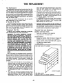
TIRE REPLACEMENT ........................ 49
If You Get A Flat Tire ................... 49
Changing A Flat Tire .................... 49
Required Tools And Equipment ............. 49
Ford Chassis .......................... 50
Chevrolet And Oshkosh Chassis . . . . . . . . . . . 50
To Change A Front Tire .................. 50
To Change A Rear Tire .................. 51
Mor/Ryde Tag Axle ..................... 52
TABLE
OF
INTRODUCTION. . . . . . . . . . . . . . . . . . . . . . . . . . .. 1
Planning And Preparation ................... 2
Loading And Weight Distribution .............. 2
Have It All Under Control ................... 2
Inspect And Maintain ...................... 2
The Owner's Information Package ............. 2
Chassis And Vehicle Identification ............. 3
Keys And Locks .......................... 3
Emergency And Identification Information ....... 4
Pre-Travel Check List ....................... 6
Cockpit And Driver's Controls ................ 7
Driver/Passenger Seats .................... 8
Seat Belts ............................. 8
Child Restraint .......................... 9
Sunvisors ............................. 9
Front/Side Slider Windows ................. 9
Driving And Parking ....................... 9
Fuel And Fuel Systems .................... 10
Fuel Fill .............................. 10
Fuel Types And Vapor Lock ............... 10
Alternative Fuel Types ................... 10
Overheating ........................... 10
Variable Speed Engine Fan ................ 10
Engine Exhaust System Component Heat ...... 10
Carbon Monoxide Safety Precautions ......... 10
Safety Tips ............................. 11
Engine Access ......................... 11
Tires . . . . . . . . . . . . . . . . . . . . . . . . . . . . . . . 11,49
Towing ................................ 12
ON THE ROAD ............................ 13
Motor Home Loading ..................... 13
Carrying Capacity . . . . . . . . . . . . . . .. . . . . . . 13
Determining and Distributing Your
Motor Home Load ........................ 13
Weighing Your Loaded Motor Home. . . . . . . .. 13
Weighing Your Loaded Motor Home
- Tag Axle Models. . . . . . . . . . . . . . . . . .. 14
Loading Tips .......................... 15
Trailer Hitches And Towing ................. 15
Towing Automobiles ..................... 15
LIVING WITH YOUR MOTOR HOME ............. 16
Manual Entry Steps ..................... 16
Power Entry Steps ...................... 16
Entry Assist Handle (Selected Models Only) ... 16
Entry Doors, Screens, And Locks ........... 16
Windows ............................. 16
Emergency Exit Window ................. 16
Storage ............................... 16
Exterior Compartments ................... 16
Interior Storage ........................ 17
Interior And Furnishings . . . . . . . . . . . . . . . . . . . 17
Dinette Conversion ...................... 17
Sofa/Lounge Conversion .................. 17
Folding Doors ......................... 17
CONTENTS
Interior Lighting ........................ 17
Overhead Vents ........................ 17
Effects Of Prolonged Occupancy ............. 18
Controlling Moisture Condensation . . . . . . . . . . . 18
Fire Safety ............................. 18
Smoke Detector ........................ 19
PLUMBING SYSTEMS ......... " . . .. .. . . . . . . 20
Fresh Water System ...................... 20
Water Purifier System ................... 21
The Water Pump ....................... 21
The Monitor Panel ...................... 21
Sanitizing The Fresh Water System ......... 22
Troubleshooting The Fresh Water System ..... 22
Leaks ............................... 22
Clogged Water Filter .................... 22
Water Pump Troubleshooting .............. 22
The Waste Water System . . . . . . . . . . . . . . . . . . 23
Toilet ................................ 23
Toilet Maintenance ...................... 23
Toilet Troubleshooting ................... 24
Dumping The Holding Tanks .............. 24
Holding Tank Care And Maintenance ........ 25
Water System Winterizing .................. 25
ELECTRICAL SYSTEMS ...................... 26
Chassis Electrical System .................. 26
Chassis Bulbs and Fuses ................. 26
12-volt Coach System .................... 26
Auxiliary Battery ....................... 26
Battery Inspection and Care .............. 26
Battery Charging ....................... 27
Selecting A Replacement Battery ........... 27
120-volt AC System . . . . . . . . . . . . . . . . . . . . . . 27
The Power Converter .......... , ......... 27
Ground Fault Interrupter ................... 27
Entertainment Equipment .................. 28
TV Antenna ............................ 28
TV "Ghosts" And FM "Flutter .............. 28
Minimizing Multipath Distortion and Improving
Signal Quality ......................... 29
Generator Power Plant .................... 29
Generator Operating Safety Precautions ...... 30
Warm Weather Operation ................. 30
Cold Weather Operation .................. 30
Preparation For Storage .................. 31
Reactivating Generator System After
Long Term Storage ...................... 31
Generator Maintenance And Service ......... 31
ELECTRICAL SYSTEM WIRING ................. 31
LPG SYSTEM .............................. 32
LP Gas Safety Precautions ................. 32
System Components ...................... 33
Hoses And Fittings ..................... 33
LP Gas Regulator ...................... 33
Using LP Gas System At Low Temperatures .... 33
Filling LP Gas Tanks ...................... 34
LP Gas System Leak Checks ............... 34
LPG Leak Detector . . . . . . . . . . . . . . . . . . . . . . . 35
Lighting LP Gas Appliances ................ 35
INTRODUCTION
your dealer will be better able to get you on the road
again.
Welcome to the recreational vehicle life-style and
the growing family of motor home owners. We
sincerely thank you for choosing a Fleetwood motor
homel
If there is anything about the warranty or what it
does or does not cover, please contact your dealer.
Your Bounder has been designed to provide you
with many years of carefree, pleasant traveling and
vacationing. This manual describes many features of
your motor home and provides an operating guide so
that you can obtain the best performance from those
features. Your motor home has been designed to conform with, or exceed, the American National Standards Institute A119.2, NFPA 501C, Canadian CSA
Standard Z-240 (units built for Canada only), and applicable motor vehicle standards. These standards
establish the plumbing, heating, electrical and other
requirements for quality and safety. Compliance with
these standards is indicated by the seal attached just
outside the entry door. This seal is the outward sign
of internal quality.
The materials in your Owner's Information Package
contain warranty information on the various appliances and components in your motor home. Warranty registration cards for these items should be filled
out and mailed as soon as possible after you take
delivery of your motor home. Your dealer can help you
with this.
You will automatically receive an Ownercare Card
approximately 3-4 weeks after delivery of your new
Bounder. This plastic card is imprinted with your
name, the motor home serial number, and manufacturing plant location. If your motor home ever needs
warranty service, present this card to the dealer.
Always return your motor home to the selling dealer
for warranty service. If this is not possible, you may
contact any other authorized Bounder dealer, or any
authorized Fleetwood motor home dealer. The service department at any of the plants listed on the
inside back cover of this manual can help you find
a dealer in your area.
Like all finely crafted equipment, your Bounder will
require care and regular maintenance in order to
deliver maximum value and performance. The dealer
will give you basic operating and maintenance instructions; however, supplement this instruction by reading
all instructional material furnished with the motor
home in the Owner's Information Package and
Chassis Operator's Manual. If, after taking delivery
of your new motor home, you feel it requires additional conditioning or adjustment, please return it to
. your dealer as soon as possible. This Owner's Manual,
along with the information provided in your Owner's
Information Package and Chassis Operator's Manual
outlines important areas of maintenance and provides
a maintenance schedule for you to follow to ensure
safe, troublefree service from your motor home. Study
these instructions carefully before you operate the
motor home for the first time. Spend some time with
your dealer going over safety and operating instructions before you leave the dealer's lot. A good working knowledge of your motor home and how to care
for it will help you enjoy many miles and years of
recreational living.
If, for some reason, a problem is not handled to
your satisfaction:
1.
Discuss any warranty-related problems directly with the manager or owner of the dealership, giving him an opportunity to help his service department resolve the matter for you.
2.
If a problem arises that cannot be resolved to
your satisfaction by your local dealer, contact
the factory service manager. The factories are
listed in this manual. Please contact the one
nearest you.
3.
We sincerely believe that your dealer and the
factory representative will be able to solve any
problem which might arise. If their combined
efforts are not satisfactory, please send a letter describing the circumstances to:
If you have any questions regarding operation,
maintenance, or service, please contact your dealer
immediately so he can assist you. Your dealer's'Service or Sales Department will handle any normal problems which might occur.
Fleetwood Enterprises, Inc.
Consumer Affairs Department
P.O. Box 7300
Riverside, CA 92523
Please include the brand name and serial
number of your motor home. The serial number
is located on the identification tag next to the
entry door.
Your motor home is covered by one of the most
comprehensive warranty programs in the RV industry,
and this manual contains a section outlining the warranty and explaining your rights and obligations, as
well as the rights and obligations of the dealer and
manufacturer, under the terms of the warranty. Please
read this section carefully. You will be better informed in case you have a warranty-related problem, and
4.
If you wish to call for assistance, please use
these toll-free telephone numbers:
From California: (800) 442-4804
From outside California: (800) 854-4755
1
NOTE: Some equipment and features described
or shown in this manual may be optional on
some models. This instructional manual is of
general nature only. Because of the continuous
program of product improvement conducted by
Fleetwood, it is possible that recent product
changes may not be included in this manual.
Specifications may change without notice. The
instructions included in this manual are intended as a guide, and in no respect extend the
responsibilities of the manufacturing subsidiary,
parent company or affiliates beyond the standard written warranty as presented in this
manual.
are going to get the most out of the convenience and'
safety items built into your vehicle. Be as familiar with
it as you are with your personal car or truck. The
booklets included in your Owner's Information
Package cover details of operation for the major appliances and equipment built into your motor home
for your comfort, convenience and safety. Later sections in this manual will also explain how to operate,
maintain, and service important components and
systems in your motor home.
LOADING AND WEIGHT DISTRIBUTION
Proper loading is one of the most important considerations when traveling in an RV. Your motor home
is built to safely carry a certain maximum load. For
safety'S sake, NEVER OVERLOAD THE MOTOR HOME.
This manual contains a detailed section that explains
proper loading and weighing of the vehicle.
Photographs or illustrations in this manual are
representative of function and may not be
specific in their depiction of actual equipment,
fabrics, interior or exterior decor or design options as installed on or in your motor home.
HAVE IT ALL UNDER CONTROL
NOTE: This product is designed for recreational
use and short term occupancy only. It is not
designed or intended to be used as permanent
housing. Use of this product for long term or
permanent occupancy may lead to premature
deterioration of interior finishes, fabrics,
carpeting, and drapes. Damage or deterioration
due to long term occupancy may not be considered normal, and may under the terms of the
warranty, constitute misuse, abuse, or neglect,
and may therefore reduce your warranty protection. This manual contains a discussion of long
term occupancy problems. Please refer to that
section before considering this product for long
term occupancy.
Remember, your new motor home is a large vehicle and requires different driving skills than a
passenger car. Later in this manual we'll outline some
tips on how to become familiar with the handling
characteristics and driving techniques that you need
to know to be a safe motor home driver. Of course,
don't overlook the laws of your state or province that
govern driving a motor home. Your state or provincial
Motor Vehicle Department can provide you with the
applicable vehicle codes that spell out your rights and
responsibilities as a motor home owner.
INSPECT AND MAINTAIN
Follow a consistent schedule of inspection and
maintenance for your motor home. Your continuing
safety and comfort depend on it. This manual includes
a section outlining maintenance intervals. Adherence
to these schedules will minimize the possibility of
failure of any important system or part of your motor
home. The time spent inspecting and maintaining your
motor home will provide you with many years of
recreational pleasure.
The motor home has been thoroughly inspected
before shipment. YOUR DEALER IS RESPONSIBLE
FOR PERFORMING A COMPLETE PREDELIVERY INSPECTION OF THE CHASSIS AND ALL MOTOR
HOME COMPONENTS AS SPECIFIED IN THE
PREDELIVERY CHECKLISTS SUPPLIED BY THE
MOTOR HOME MANUFACTURER AND THE CHASSIS
MANUFACTURER. YOU SHOULD RECEIVE A COPY
OF THESE COMPLETED CHECKLISTS FROM YOUR
DEALER WHEN YOUR MOTOR HOME IS DELIVERED
TO YOU.
THE OWNER'S INFORMATION PACKAGE
AS A PART OF THE PREDELIVERY INSPECTION PROCEDURE, THE DEALER IS TO ROAD TEST THE
MOTOR HOME, NOTING AND CORRECTING ANY
STEERING PROBLEMS BEFORE DELIVERY.
THEREFORE, FLEETWOOD AND ITS SUBSIDIARIES
WILL NOT BE RESPONSIBLE FOR FRONT END ALIGNMENT AFTER THIS PREDELIVERY INSPECTION IS
DONE.
PLANNING AND PREPARATION
Each year millions of Americans embark on trips
using some type of recreational vehicle. Proper planning of your trip will ensure a pleasurable experience.
A thorough knowledge of your RV is important if you
2
Key No.: _ _ _ _ _ _ _ _ _ _ _ _ _ __
This package contains very valuable documents
about your motor home and its components and
systems. This Owner's Manual is in this package.
Since this owner's manual does not cover every possible detail of equipment and options installed on or
in your motor home, there are booklets and instructional material in the package that will help you safely operate, maintain and troubleshoot those items. Be
sure you read all this information and understand the
safety and operating instructions included in the
package. Keep these references handy. If you ever
decide to sell or trade your motor home, be sure the
new owner gets all the material in this package.
Other Sources Of Information
Since everyone's recreational and travel needs are
different, many good publications are available for
RV'ers. These books and magazines offer many tips
and guidelines ranging from safe operation of your
RV to regional recipe favorites, travel hints and directories of all kinds. Many of them contain first-person
accounts of experienced RV'ers that can be both
entertaining and informative.
CHASSIS AND VEHICLE IDENTIFICATION
Several numbers are used to identify the vehicle
and components used on the vehicle. The V.I.N. or
Vehicle Identification Number is the legal identification of the completed vehicle and is the number on
tt)e vehicle registration. The V.I.N. is found on the DOT
certification tag attached to the left sidewall of the
motor home driver compartment. Refer to this information when ordering parts from the chassis
manufacturer or chassis dealer service center. The
Fleetwood Identification Number IF.I.N.) is located on
the plate just outside the main entry door and on the
outside left front side of the motor home. Use this
number when ordering parts through your Fleetwood
dealer or Service Center.
The following is a list of publishers that may be
of interest:
TL Enterprises
29901 Agoura Road
Agoura, CA 91300
Intertec
P.O. Box 12901
Overland Park, KS 66212
Woodall Publishing Co.
Box F
Highland Park, IL 60035
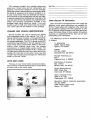
KEYS AND LOCKS
Trail-R-Club of America
Box 1376 B
Beverly Hills, CA 90213
The keys to your motor home are pictured below.
Record all key numbers and keep them in a safe place
at home and in the motor home.
Family Motorcoaching
8291 Clugh Pike
Cincinnati, OH 45244
Scott, Foresman & Co.
1909 K St. N.w.
Washington, D.C. 20049
Recreation Vehicle Industries Association
P.O. Box 2999
.
1896 Preston White Drive
Reston, VA 22090
3
EMERGENCY AND IDENTIFICATION INFORMATION
Before we explain how things work, take a few minutes to fill in the information on these two pages.
It'll be a handy reference for you in the future.
Your Name ____________________________________________________________________
Model ____________________________________________________________________
Serial Number ______________________________________________________________
Date Purchased _________________________________________________
Dealer Name __________________________________________________
Address ________________________________________________________________
Insurance Policy
Company ________________________________________________________________
Agent Name _________________________________________________________________
Telephone __________________________________________________________________
Policy Number _______________________________________________________________
Range/Oven
Manufacturer ___________________________________________________
Model ___________________________________________
Serial Number _ _ _ _ _ _ _ _ _ _ _ _ _ _ _ _ _ _ _ _ _ _ _ _ _ _ _ _ _ _ _ _ _ ___
Refrigerator
Manufacturer _ _ _ _ _ _ _ _ _ _ _ _ _ _ _ _ _ _ _ _ _ _ _ _ _ _ _ _ _ _ _ _ _ _ ____
Model ___________________________________________
Serial Number _ _ _ _ _ _ _ _ _ _ _ _ _ _ _ _ _ _ _ _ _ _ _ _ _ _ _ _ _ _ _ _ _ ___
Furnace
Manufacturer __- - - - - - - - - - - - - - - - - - - - - - - - - - - - - - - - - - - - - Model _________________________________________________
i .
• Serial Number _ _ _ _ _ _ _ _ _ _ _ _ _ _ _ _ _ _ _ _ _ _ _ _ _ _ _ _ _ _ _ _ _ ___
4
Water Heater
Manufacturer________________________________________
Model _____________________________________________________________________
Serial Number____________________________________
Air Conditioner
Manufacturer·__________________________________________
Model ____________________________________________________________________
~--
Serial Number______________________________________
Microwave Oven
Manufacturer__________
~
___________________________
Model ________________________________________________________________________
Serial Number______________________________________
Stereo
Manufacturer______________________________________
Model _______________________________________
Serial Number_________________________________________
Generator
Manufacturer_________________________________________
Model ________________________________________________________________________
Serial Number_______________________________________
Miscellaneous
Key Number____________________________________
5
PRE:rRAVEL CHECK LIST
Exterior
Disconnect water, electrical, and drain lines
Check roof top carrier (if installedl
Remove blocks from wheels
Check wheel nut torque. (See chassis Operator's Manual)
Check LPG tank level and refill if necessary
Check hitch and hitch ball
Check tires and adjust pressures if necessary
Check batteries
Check running lights, turn signals, interior and panel lights
Check brakes, brake fluid, brake lights
Check cooling system
Check windshield wipers, washers, and washer fluid
Retract step
Interior
Lower TV antenna
Lock refrigerator door
Turn off water heater
Turn off water pump
Turn off furnace
Turn off range pilot
Close cooktop cover
Close roof vents
Close all doors, drawers and windows
6
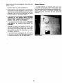
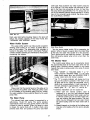
COCKPIT AND DRIVER'S CONTROLS
Consult Chevrolet or Oshkosh Operator's Manual
for additional information.
The Auxiliary Start System has no effect on the
vehicle except to aid in starting the motor home
engine. If the vehicle alternator is operating properly, the batteries will be recharged while driving (see Electrical System).
The main instrument cluster and switches are located
on a hinged panel directly in front of the driver. The
panel lifts up allowing access to fuses, wiring and instruments below and behind the panel.
The auxiliary start system will engage
automatically when the main (chassis) battery
charge is insufficient to crank the engine. The
instrument panel indicator will show either of
two normal conditions when the ignition switch
is turned to the "CRANK" position:
Parking Brake - The parking brake lever is
located on the floor near the left driver wall. Pull
the lever up to set the brake, push down to
release.
Cruise Control - The cruise control is located
either on the turn signal lever (Chevrolet chassis)
or the steering wheel (Oshkosh chassis).
1.
GREEN - the main battery is charged, and capable of cranking the engine.
Cranking power is being provided by
the main battery. The green indicator
will remain on for approximately 10
seconds after cranking.
2.
ORANGE - The main battery has insufficient charge for engine cranking. The
auxiliary battery system has been activated to crank the engine. The orange
indicator will remain on for approximately 10 seconds after cranking.
WARNING: Do not use the cruise control on slippery
roads or in congested traffic.
NOTE: See Chassis Operator's Manual before engaging system.
Headlight Switch - The three-position light
switch controls the headlights, taillights, parking lights, sidemarker lights and instrument lights.
Instrument light intensity can be varied by turning knob clockwise or counterclockwise.
Of course, if both the main and auxiliary batteries are dead, the engine will not crank, nor
will the panel indicator light up. Sufficient cranking charge may be restored to the auxiliary batteries by plugging in to an external 110V AC electrical source or by running the generator.
The headlight circuit is protected by a circuit
breaker in the light switch. An overload on the
breaker will cause the lights to "flicker" on and
off. If this condition develops, have your headlight
wiring checked immediately.
2-Speed Windshield Wiper/Washer with DelayTurn inner knob clockwise for wiper action. The
wiper blades are mounted on "articulated" arms
that allow the blades to follow a wiping path as
wide as possible.
NOTE: If extended normal driving does not
recharge the batteries, see an authorized Fleetwood motor home service center.
NOTE: A system override switch is located under
the instrument panel housing. If the main battery is discharged to a level that is too low for
the automatic system to sense and activate, the
override switch will lock in the solenoid directly
to the auxiliary batery to provide cranking power.
OFF-No wiper action.
1st notch-Wiper delay ON. Turn knob
clockwise for longer delay between wiper
strokes.
Instrument Cluster
2nd notch-Slow wiping action.
Radio/Tape Player
3rd notch - Fast wiping action.
Monitor Panel
Transmission Selector - Pull transmission lever
toward you and move to desired position. Please
refer to the Chassis Operator's Manual for more
details on transmission operation.
To WASH, press knob, then release. One press
of washer knob cycles wipers once. The washer
nozzles are located on the wiper arms close to
the wiper blades. They move with the blades and
provide continuous washer coverage.
Generator Remote Start/Stop Switch
Auxiliary Start System - The Auxiliary Start
System permits using the auxiliary battery (see
Electrical System) to start the motor home engine
if the vehicle battery is discharged.
Cigarette Lighter
Heater/Air Conditioner Controls - The cockpit
Heater/Air Conditioner controls are located on the
lower right instrument panel. These controls
operate the heating and air conditioning systems
for the driver/cockpit area only.
• Before engaging system, be sure the vehicle
is stopped, shift to "P" (PARK) and apply the
parking brake.
7
Cool/Heat Lever-Push this lever to the left
or right for cooling/heating.
Function Selector Buttons
OFF - No heating or cooling, but fan runs
at low speed for continuous circulation of
outside air through the instrument panel
outlets.
MAX AlC-Air conditioner compressor is
on, inside air is recirculated through the
system for maximum cooling.
AlC-Air conditioner compressor is on, outside air is circulated through instrument
panel outlets.
The driver's and.passenger's seats offer four position/comfort adjustments:
CAUTION: Do not adjust the seat position while the
vehicle is in motion.
*
Forward/Back - The forward/back lever is located
under the front left of the seat.
Pull the lever torward the left outside of the seat
to unlock. Release the lock lever to secure the seat
position.
Swivel - The swivel lock lever is located under
the front right of the seat.
Lift the lever forward and up to swivel. The seat
locks in the center, forward position. When unlocked, the seat will swivel freely around to the center
position.
Recline and Lumbar Adjustment - The recliner
*
lever is located on the seat arm.
Push the lever to recline. The angle is continuously variable. Release lever at desired angle.
Turn the lumbar adjuster at the side of the seat as
desired.
*
VENT-AiC compressor is off, outside air
is circulated through the instrument panel
outlets.
HEAT-A/C compressor is off, outside air is
circulated through the heating system, and
distributed to floor outlets.
Heated air is circulated to defroster outlets.
Fan Switch - Sets fan speed to any of 4
speeds. The fan switch does not affect the
fan if the OFF function button is pressed.
Seat Belts
Seat belts are an important safety feature of your vehicle. For your protection, always use your seat belts. The
driver's seat and other seats designed to carry
passengers while under way have been equipped with
seat belts.
Ignition Switch - Operation of the ignition
switch is shown below.
Tilt Steering Wheel.
WARNING: ALL RIDERS SHOULD BE FURNISHED WITH AND USE SEAT BELTS WHILE THE VEHICLE IS IN MOTION. SEATS WHICH ARE NOT
EQUIPPED WITH SAFETY BELTS SHOULD NOT BE
OCCUPIED WHILE THE VEHICLE IS IN MOTION
AND WILL BE LABELED: "NOT FOR USE WHILE
THE VEHICLE IS IN MOTION." IT IS NOT POSSIBLE TO BELT IN PERSONS USING BEDS.
Hazard Warning Flasher.
Adjust seat belts as follows:
ACC
OFF
ON
START
Driver/Passenger Seats
*
Pivot buckle at right angles to the belt and pull
to the desired length.
*
To fasten belt, be sure it is not twisted, then push
the tongue end of one belt into the buckle of the
mating belt. Be sure it latches. Adjust the belt snugly as low on the abdomen as comfort will allow,
for greatest safety.
* To release the belt, depress the button in the center
of the buckle and slide the tongue out of the buckle.
Never use a belt for more than one person at a time.
Child Restraint
All vehicle occupants, and especially children, should
be restrained whenever riding in vehicles. Holding a child
in your arms is not a substitute for a child restraint
system. In an accident, a child held in a person's arms
can be struck or crushed by any unrestrained rider. An
unrestrained child could also be injured by striking the
interior, or by being thrown from the vehicle during'a
Seat Controls
8
"
particularly in traffic and in gusty wind conditions,
sudden maneuver or impact A child restraint system
can help protect a child while riding in a vehicle, Child
restraint systems are designed to be secured in the vehicle seats by lap belts or the lap portion of a lap-shoulder
belt, Children could be endangered in a crash if their
child restraints are not properly secured in the vehicle.
Driving on winding or mountain roads is not difficult
if done with reasonable care, Observe proper vehicle
speeds when ascending or descending hills and always
operate in the proper transmission range. Downshift on
hills to avoid overheating or undue engine loads,
Downshift when descending grades, Engine braking
power will help control vehicle speed, and relieve some
of the strain on the brakes,
Children small enough for a child restraint system
should be restrained that way if at all possible. However,
the following may provide some degree of protection
if a child restraint is not used,
•
•
Road conditions, terrain, weather, and other driving
factors are sometimes unpredictable, and mountain driving or desert temperatures can put extreme demands
on drivetrain components-especially the transmission,
Under extreme heat conditions you may need to turn
off the vehicle air conditioner to improve engine and
transmission cooling.
Allow for the extra height of your motor home and
avoid areas having low overhead clearance, Check for
lOW-hanging tree branches or other obstructions
whenever you drive or park. Avoid low roofs when pulling in for service, Always check overhead clearances
of overpasses and bridges, This may be particularly important if you drive with the overhead vents open or
if the motor home is equipped with a roof air conditioner, roof rack, CB or TV/radio antenna.
Infants who cannot sit up should be placed in a
padded baby carrier. Put it crosswise on the vehicle
seat and securely restrain it with the vehicle's seat
belts.
Children who can sit up by themselves should be
restrained with the seat belts provided. Never let
a child stand or kneel on any seat,
When using any child restraint system, be sure to read
and follow all instructions on installation and use that
come with the system,
When securing a child restraint with a lap belt that
has no retractor, pull the excess webbing through the
adjustment mechanism,
If the child restraint is still not secure, use a different
seating position in the vehicle and/or contact your dealer
and the child restraint manufacturer for help,
When parking parallel to a curb, be sure to allow for
poles or obstructions as the front and rear portions of
the motor home swing wider than an automobile, When
parking on an incline, turn the front wheels into the curb
in the direction of the roll to aid the parking brake. Always
shift the transmission to PARK ("P"I and set the parking brake when parking,
Sun Visors
The sun visors at the driver's and passenger's positions swing down and adjust to provide relief from glare
and bright skies. The visors do not adjust to shade the
side windows,
· Swivel tension may be adjusted with a flat blade
screwdriver at the tension adjusting screw,
FUEL AND FUEL' SYSTEMS
Turn lock, slide window and/ or screen to open and
close,
See the Chassis Operator's Manual in the Owner's
Information Package for fuel recommendations, Since
the generator fuel supply is the same as the motor home
engine fuel supply, consult the operating instructions
for the generator before deciding on a fuel type,
DRIVING AND PARKING
Fuel Fill
Once you become accustomed to the feel of the controls and the reference points from the driver's seat, you
will find driving the motor home comparable to driving
your family car. Become familiar with the position of
the motor home in traffic, and be cautious when
maneuvering to allow for the length and width of the
vehicle. Always allow extra room to corner and to change
lanes, learn to use the side mirrors to view the road
behind. Check them often,
The fuel filler cap is located on the rear of the coach,
Modern fuel systems may build up vapor pressure within
the tank as the gasoline warms during use or hot
weather, Under certain conditions, sudden release of this
pressure when removing the gasoline cap can spray
gasoline from the fill opening, causing a possible hazard,
WARNING: WHEN REMOVING THE GASOLINE
CAP. ROTATE IT SLOWLY ONLY FAR ENOUGH TO
ALLOW PRESSURE TO RELEASE. AFTER ANY
"HISSING" SOUNDS STOP. COMPLETE THE
REMOVAL OF THE CAP.
To protect the gasoline system from excessive pressure
or vacuum, or from sudden release of pressure, replace
lost caps with caps of the same design available from
your Fleetwood motor home dealer.
Clean up fuel spills immediately, Raw fuel spilled on
the motor home could damage the exterior finish, and
is a serious fire hazard.
Front/Side Slider Windows
Drive with consideration on the highway, observing
all speed and safety regulations. The best cruising speed
of your motor home will vary with road and weather
conditions.
Remember that your motor home is heavier than a
car, making it less maneuverable and harder to stop.
Also, because of its greater side surface area, it is more
easily affected by cross winds. Allow extra distances
for passing and stopping, and drive at a moderate speed,
9
Fuel Types And Vapor Lock
the materials in the fuel lines can cause deterioration
of the fuel lines during storage periods. These effects
are especially noticeable with gasohol blends. If you plan
to use alcohol blended fuel, and expect to store your
motor home for periods of 60 days or more, add a fuel
additive that is formulated to counteract these oxidation effects. Your dealer can advise you on the proper
additives and their use.
If gasohol is spilled on a painted surface, some dulling or softening of the paint may result.
Today's automotive fuel and emissions systems are
sophisticated and highly engineered to meet Federal and
state emissions standards. They are also sometimes sensitive to fuel types and blends, particularly blends that
are optimized for climatic conditions. Fuel refiners change
the additives in the fuel to compensate for temperature
variations during winter or summer months. This compensation changes the "vapor pressure" of the fuel. This
means that the fuel vaporizes easier during the winter
than it does during the summer when higher air
temperatures help the fuel vaporize in the engine. Since
colder temperatures reduce the fuel's ability to vaporize
and burn in your engine, additives help raise the volatility of the fuel. This helps the engine start easier and
run smoother during winter months. Under the best of
conditions, the refiners supply their gas station customers
with the correct fuel for their location and seasonal conditions. Sometimes though, fuel blended for winter is
supplied during summer months.
What this all means is that there is a possibility of
"vapor lock" during summer driving. This condition is
a combination of new engine design (with attendant
higher temperatures under the hood), and excessive fuel
vaporization caused by the vapor pressure of the fuel
you are using. If your engine and fuel system are properly tuned and maintained, you should not experience
vapor lock. If vapor lock occurs, the fuel itself could
be the cause. If at all possible, check with the gas station attendant as to the fuel blend before filling your
fuel tank. If you purchase your fuel from nationally
recognized fuel dealers, your chances of vapor lock can
be reduced. If you store your motor home during the
winter months, avoid storing large quantities of winter
blended fuel in the tank. When you take the vehicle out
of storage in the spring or summer, this fuel may cause
vapor lock until it is used up.
Another note on long storage - if you plan to store
your motor home for a long period in conditions of widely
varying humidity, consider topping off the fuel tank. This
will reduce the buildup of condensation in the tank that
could cause rough engine operation, fuel filter blockage,
or other problems associated with water in the fuel.
Overheating
Operate and service the engine and Gooling systems
in your vehicle as recommended in the Chassis
Operator's Manual.
Variable Speed Engine Fan
Your motor home engine is equipped with a variable
speed fan clutch. When the engine is under load or requires maximum cooling, the fan adjusts and turns faster.
The fan may become very noisy at high speed and when
maximum cooling is required. When the engine doesn't
need maximum cooling, the fan just idles along. This
conserves fuel and the fan is less noisy.
High speed fan noise can sometimes be misinterpreted
as transmission slippage. This is not the case. When
the engine is hot and requires extra cooling, the fan turns
at full speed. High engine speed and temperature conditions, such as pulling away from a stop after long
freeway driving, can cause loud fan noise until the engine
cools down. This fan noise indicates that the fan is doing what it is supposed to do. This noise is not a defect
in the fan or the transmission.
ENGINE EXHAUST SYSTEM COMPONENT HEAT
Your motor home engine has been designed to conform with Federal and State emission requirements. To
meet these requirements, engine operating temperatures
are high. As a result, the engine and exhaust system
components radiate a great deal of heat. Parts of the
exhaust system may operate at temperatures near 700
degrees F. The temperatures are normal for your vehicle.
Special heat shields may be built into your vehicle
to protect wiring or other components from possible
heat damage caused by the exhaust system. Do not
modify or remove these shields without consulting your
RV dealer. If you want to install equipment, add wiring,
plumbing, or other components near the exhaust system
or the heat shields, do so only after you thoroughly investigate and understand how the equipment will be
affected by the heat radiated by the exhaust system.
Alternative Fuel Types
Gasohol, a mixture of ethanol (grain alcohol), or
methanol and gasoline may be used in your motor home
engine without voiding the warranty. However, DD NOT
UNDER ANY CiRCUMSTANCES USE FUEL BLENDS
CONTAINING MORE THAN 5% METHANOL OR 10%
ETHANOL, AND DO NOT USE BLENDS THAT CONTAIN
BOTH METHANOL AND ETHANOL. Any fuel blend you
use containing alcohol must also contain cosolvents and
other additives to protect the fuel system components.
If you are not sure of the composition of the
alcohol/gasoline blend you intend to use, ask your service station operator. Discontinue use of any
alcohol/gasoline blend if driveability or fuel system problems occur.
Chemical reactions between the fuel components and
CARBON MONOXIDE SAFETY PRECAUTIONS
Carbon monoxide is a colorless, tasteless, odorless
gas. It is a by-product of combustion in engine(s). The
engines in your motor home and generator system (if
installed) produce it constantly while they are running.
CARBON MONOXIDE IS DEADLY. Please read and
understand the following precautions to protect yourself
and others from the effects of carbon monoxide
poisoning.
10
WARNING: EXHAUST GASES ARE DEADLY. DO
NOT BLOCK THE TAILPIPES OR SITUATE THE
VEHICLE IN A PLACE WHERE THE EXHAUST
GASES HAVE ANY POSSIBILITY OF ACCUMULATING EITHER OUTSIDE, UNDERNEATH, OR INSIDE
YOUR VEHICLE OR ANY NEARBY VEHICLES.
OUTSIDE AIR MOVEMENTS CAN CARRY EXHAUST GASES INSIDE THE VEHICLE THROUGH
WINDOWS OR OTHER OPENINGS REMOTE FROM
THE EXHAUST OUTLET. OPERATE THE ENGINE(S)
ONLY WHEN SAFE DISPERSION OF EXHAUST
GASES CAN BE ASSURED, AND MONITOR OUTSIDE CONDITIONS TO BE SURE THAT EXHAUST
CONTINUES TO BE DISPERSED SAFELY.
Instruct your family on what to do in case of fire,
and hold fire drills periodically.
Maintain proper charge in the fire extinguisher.
Gas detectors are available from RV equipment dealers,
and may be considered as safety accessories.
Keep a well stocked first-aid kit handy.
Keep a tool box handy.
Check tires often while traveling. Inside rear duals
should receive special attention, as these tires may go
flat and not be noticed. Running a flat on an inside dual
could lead to a tire fire that would be extremely difficult to extinguish. Make it a habit to check tire
pressures with an accurate tire gauge before each trip,
and when re-fueling give each tire a sharp rap on the
tread surface with a hammer or similar object. Properly
inflated tires produce a "bung" sound when rapped.
If the tire is flat, the sound will be a dull "thud".
Beware of exhaust gas (carbon monoxide) poisoning
symptoms:
Dizziness
Intense Headache
Weakness and Sleepiness
Vomiting
Muscular Twitching
Throbbing in Temples
If symptoms indicate the possibility of carbon monoxide poisoning, turn off the engine(s) immediately, get
out into fresh air at once, and summon medical
assistance.
Engine Access
The top of the engine may be accessed for service
by removing the engine cover. Remove the two access
cover screws and lift off the cover. When replacing the
screws, be careful to get them in straight.
WARNING: WHEN INSTALLING THE ENGINE
COVER, BE SURE THE COVER IS FULLY SEATED
ON THE GASKET SEAL AND SECURED BY THE
COVER SCREWS. DO NOT ALLOW CARPETING,
FLOOR MATS OR OTHER MATERIAL TO INTERRUPT THE SEAL BElWEEN THE COVER AND THE
ENGINE COMPARTMENT. IF THE ENGINE COVER
IS NOT INSTALLED CORRECTLY, ENGINE EXHAUST GASES COULD LEAK INTO THE
PASSENGER COMPARTMENT CREATING A SAFETY HAZARD. IF THE ENGINE MUST BE RUN WITH
THE ENGINE COVER OFF FOR MAINTENANCE
PURPOSES, BE SURE THE VEHICLE INTERIOR IS
ADEQUATELY VENTILATED.
WARNING: DO NOT UNDER ANY CIRCUMSTANCES OPERATE ANY ENGINE WHILE
SLEEPING.
You would not be able to monitor outside conditions
to assure that engine exhaust does not enter the interior, and you would not be alert to exhaust odors or
symptoms of carbon monoxide poisoning.
During stops while traveling, inspect the exhaust
systems for road damage. Do not operate an engine with
a damaged exhaust system.
Check the exhaust system(s) during routine
maintenance, and repair any leaks, damage, or obstructions before further operations.
Do not mOdify the exhaust system(s) in any way
without first consulting the RV manufacturer.
SAFETY TIPS
Read and understand the Chassis Operator's Manual.
When backing the motor home, have a person stand
to the rear on the driver's side to guide you.
Before departing on a trip, check your routes.
Remember, some tunnels prohibit motor homes with LP
gas systems.
Drive at moderate speeds, particularly in traffic and
in gusty wind conditions.
Allow extra distance for passing and stopping.
While traveling, make sure all occupants use their seat
belts.
Engine Cover
While traveling, make sure all doors are closed and
cabinets, drawers, and loose objects are secure.
Your motor home is equipped with truck tires. Under
normal circumstances and with proper maintenance, you
TIRES
11
should receive thousands of miles of troublefree service.
For safety and maximum tire life, proper inflation
pressure must be maintained. Motor home stability is
also affected significantly by tire pressure, and properly
inflated tires contributes to overall motor home stability
and safety. The load range and maximum inflation
pressure are stamped on the tire side wall. Keep tires
inflated to this rated cold pressure.
The vehicle may be towed on the rear wheels with
the par.king brake released and the transmission in
neutral provided a speed of 35 MPH and a distance
of 50 miles is not exceeded. If this speed or distance
must be eceeded, disconnect the driveshaft or place
the rear wheels on a dolly.
The safety of the operator and all other persons
in the vicinity of the tow truck and the towed vehicle must be considered at all times during a towing
operation. DO NOT ALLOW ANY PERSON TO RIDE
IN THE TOWED VEHICLE. Safe operating speeds depend on weather, road, traffic, and visibility conditions, and the condition of the towed vehicle. Avoid
panic stops. Obey all state and local laws regarding
items such as warning signals, night illumination,
speed, etc.
WARNING: CHECK TIRE PRESSURES OFTEN.
ALWAYS CHECK PRESSURE WHEN TIRES ARE
COLD, AND DO NOT BLEED AIR OUT OF WARM
TIRES. FOLLOW THE TIRE PRESSURE INSTRUCTIONS IN THE CHASSIS OPERATOR'S MANUAL.
WARNING: KEEP TIRES PROPERLY INFlAJ'B). A TIRE
THAT IS RUN LONG DISTANCES OR AT HIGH
SPEEDS WHILE SERIOUSLY UNDER-INFLATED WILL
OVERHEAT TO THE POINT WHERE THE TIRE MAY
LOSE AIR SUDDENLY AND/OR CATCH FIRE,
POSSIBLY RESU01NG IN DAMAGE 10 THE VEHICLE
AND ITS CONTENTS AND/OR PERSONAL INJURY.
NOTE:
CHECK THE WHEEL COVERS
PERIODICALLY. THEY COULD WORK LOOSE
DURING DRIVING.
Before towing the motor home:
TOWING
If your motor home ever needs to be towed, the only
safe and approved towing methods are either an underreach wheel lift device as installed on a minimum 3-ton
tow truck chassis, or a flat bed trailer.
Most tow truck operators willing and able to tow
motor homes will be familiar with these devices.
If the motor home's rear wheels are disabled, the vehicle must be transported on a flat bed trailer, or use a
heavy duty dolly under the rear wheels and tow from
the front. Do not tow the motor home from the rear.
Towing from the rear will cause serious overloading of
the front tires and suspension, possibly resulting in tire
or front suspension failure.
12
•
Secure any loose or protruding parts of the
disabled vehicle.
•
Inspect the lift device atachment points. If these
points are damage, select other attachment
pOints, if possible.
•
Never allow anyone to go under a vehicle while
it is being lifted by towing equipment unless the
disabled vehicle is adequately supported by safety stands.
•
Turn off LP gas appliances and the LP gas tank
valve.
•
Disconnect or turn off 12-volt electrical system.
ON THE ROAD
the label. These extra seating locations, if provided, are
to permit a choice of seats while traveling. It is not safe
to exceed the labeled passenger capacity unless the axle
loadings and total weight are checked against their
ratings on a public scale.
Thoughtful consideration of the weight placed in the
motor home can yield important benefits:
* maximum flexibility in the use of the seating and
liberal storage facilities provided in the motor home;
* operation without unsafe loading;
* improved handling characteristics and ride comfort;
• better fuel mileage and reduced tire wear.
MOTOR HOME LOADING
A motor home chassis (springs, wheels, tires, axles,
and frame) is designed to carry a certain maximum
load. This load includes everything; the weight of the
empty motor home itself, your belongings, fuel, fresh
water; waste water and anything else that may be
in or attached to the motor home. The maximum load
for which the motor home is designed is called the
GROSS VEHICLE WEIGHT RATING (GVWR).
Another critical weight factor is the GROSS AXLE
WEIGHT RATING (GAWR). This is the maximum
weight a specific axle is designed to carry and each
axle has its own GAWR. The GAWR's do not
necessarily add up to the GVWR. Be careful, neither
the axle loads nor the vehicle loads must ever exceed their respective weight ratings.
NOTE: CARRYING CAPACITIES OF YOUR MOTOR
HOME ARE SPECIFIED ON A LABEL AFFIXED TO
THE INSIDE OF A WARDROBE DOOR. THE LABEL
INCLUDES ALL FACT'ORY INSTALLED OPTIONS. IF
OTHER EQUIPMENT SUCH AS LEVELING JACKS,
AWNINGS, ROOF PODS, ETC., ARE INSTALLED
AFTER THE MOTOR HOME LEAVES THE FACTORY,
THE WEIGHT OF THESE ITEMS MUST BE SUBTRACTED FROM THE TOTAL OF THE PASSENGER
AND CARGO CARRYING CAPACITIES. IF YOU TOW
A TRAILER, THE TONGUE WEIGHT OF THE
TRAILER MUST BE SUBTRACTED FROM THE
TOTAL OF THE PASSENGER AND CARGO CARRYING CAPACITIES.
In addition to knowing the overall weight that can
be safely loaded in or attached to the motor home,
you must know how to distribute the weight so that
correct amounts of weight are placed on the axles.
The allowable carrying capacity of the motor home
is found by weighing the motor home empty, and subtracting this weight from the GVWR.
CARRYING CAPACITY
During the design and development of our motor
homes, the number and size of storage compartments,
the liquid tank capacities and number of belted seating
positions are maximized for value and convenience.
If the motor home operator fills all liquid tanks to
capacity, fills all storage compartments and cupboards
to maximum volume and fills all available seating positions with passengers, the motor home will probably
be overloaded. According to National Highway Traffic Safety Administration figures, an average vehicle
occupant weighs 150 pounds, each gallon of gasoline
weights six pounds (6.0 Ibs.) and each gallon of water
weights over eight pounds (8.3 Ibs.).
DETERMINING AND DISTRIBUTING
YOUR MOTOR HOME LOAD
The Gross Vehicle Weight Rating (GVWR) and the
Gross Axle Weight Rating (GAWR) for your motor
home are shown on the certification tag posted on
the driver's door or in the driver's compartment.
Remember, these ratings are for a fully loaded vehicle. You must compare the GVWR to the loaded
weight of your motor home. If the loaded weight of
your motor home exceeds the GVWR, the motor home
is overloaded and you'll have to remove items to bring
the weight down to or below the GVWR. If the loaded axle weight on any axle exceeds the GAWR, the
axle is overloaded and you'll have to redistribute cargo
to bring the weight down to or below the GAWR.
The operator is responsible for analyzing the conditions in which the motor home will be utilized for each
trip. The number of passengers and placement of cargo
will affect the amount of water and cargo that you can
carry (See Loading lips). For convenience, the passenger
capacity for camping use and the passenger capacity
for day use are shown On a permanent label in the
driver's area or adjacent to the main entry door. The
smaller passenger capacity for camping provides
reasonable cargo capacity for trips taking more than one
day. The larger passenger capacity for day use provides
less cargo capacity for trips or acitivites not involving
overnight stays. It may be necessary to reduce the
amount of water carried and unload some cargo items
normally carried for camping in order to provide carrying capacity for the additional day use passengers.
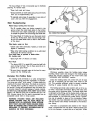
Weighing Your Loaded Motor Home
1. Drive the front wheels onto the scale platform and
take a reading. This is the front Gross Axle Weight.
(Reading 1).
2. Drive the entire vehicle (both axles) onto the scale
and take a reading. This is the Gross Vehicle Weight
(Reading 2).
3. Drive forward until only the rear axle is on the platform and take a reading. This reading is the rear
Gross Axle Weight (Reading 3).
4. Compare reading 2 with the GVWR Gross Vehicle
Weight Rating) of your vehicle. This rating is located
on the certification tag. If the reading exceeds the
The number of safety belted seating locations may
be greater than the number of passengers permitted by
13
WARNING: DO NOT EXCEED THE RATED LOAD OF
THE MOTOR HOME, OR THE RATED LOAD OF ANY
AXLE. EXCEEDING THE GAWR OR GVWR OF YOUR
MOTOR HOME CAN CAUSE UNDESIRABLE HANDLING CHARACTERISTICS AND MAY CREATE A SAFETY HAZARD.
Weighing Your Loaded Motor Home
(Tag-Axle Models)
The following weighing procedure will help you
determine whether your loaded motor home (complete with cargo, fluids, passengers, and driver) is
within GAWR and GVWR limits. When you arrive at
the weigh station, the attendant will guide you
through the correct pOSitioning of the motor home
on the scales. Generally, the sequence is as follows:
1. Drive the entire vehicle (all axles) onto the scale
and take a reading. This is the Gross Vehicle Weight
(Reading1).
GVWR rating, you will have to reduce the total vehicle load.
5. If reading 2 is less than the GVWR of your vehicle,
check readings 1 and 3 to verify that each is less
than the GAWR on the certification tag. If either
exceeds the GAWR for the axle, redistribute enough
of the load to ensure that loads on the front and
rear axles are within the required limit.
6. The motor home should also be weighed from side
to side. This will require positioning both wheels on
each side down the center of the scale platform and
taking a reading for each side. The attendant will help
you with proper positioning.
Periodically reweigh your motor home. Different
traveling configurations may change your loading and
weight pattern.
NOTE: THE PASSENGER AND CARGO CARRYING
CAPACITIES OF YOUR MOTOR HOME ARE SPECIFIED ON A LABEL AFFIXED TO THE INSIDE OF A
WARDROBE DOOR. THE LABEL INCLUDES ALL FACTORY INSTALLED OPTIONS. IF OTHER EQUIPMENT
SUCH AS LEVELING JACKS, AWNINGS, ROOF
PODS, ETC., ARE INSTALLED AFTER THE MOTOR
HOME LEAVES THE FACTORY, THE WEIGHT OF
THESE ITEMS MUST BE SUBTRACTED FROM THE
TOTAL OF THE PASSENGER AND CARGO CARRYING CAPACITIES.
2. Drive the vehicle forward until the front wheels just
clear the scale pad. This is the load on the drive
and tag axles (Reading 2).
14
3. Drive the vehicle backward until the tag axle wheels
just clear the scale pad. It is important to keep the
tag and drive wheels level for accuracy. This is the
load on the drive and front axles (Reading 3.)
TRAILER HITCHES AND TOWING
If you expect to pull a trailer with your motor home,
please use these guidelines when choosing a hitch
and trailer:
4. Subtract Reading 2 from Reading 1. This is the front
axle weight (Front GAW). Subtract Reading 3 from
Reading 1. This is the tag axle weight (Tag GAW).
Subtract front GAW from Reading 3. This is the
drive axle weight (Drive GAW).
• Hitch classification: Class II
• Limit the vertical hitch load (tongue weight of trailer)
to a maximum of 250 pounds. Heavier vertical hitch
loads can cause damage to your motor home rear
frame and body, cause unstable driving and handling
characteristics, and may restrict your rights under the
Ownercare warranty.
5. Compare the Gross Vehicle Weight (Reading 1) to
the GVWR (Gross Vehicle Weight Rating) of your
vehicle. If this weight exceeds the GVWR of your
vehicle, you will have to remove cargo to reduce
the total vehicle load.
6. Compare each axle weight to its respective GAWR
(Gross Axle Weight Rating). If any axle weight exceeds its rating, you will have to redistribute cargo
to insure that the load on each axle is within its
required limit.
• Do not tow a trailer weighing more than 3500
pounds, or more than recommended by the chassis
manufacturer (as described below), whichever is less.
Heavier trailers can cause damage to the motor home
structure or drive train, cause unstable driving or
handling characteristics, or restrict your rights under
the Ownercare warranty.
7. The motor home should also be weighed from side
to side. This will require positioning all wheels on
each side down the center of the scale platform
and taking a reading for each side. The attendant
will help you with proper positioning.
• Check the Carrying Capacity chart posted inside an
interior cabinet door to determine total weight carrying capacity for your motor home.
Periodically reweigh your motor home. Different
traveling configurations may change your loading and
weight pattern.
• Alternate gear ratios may be retrofitted for special towing needs. Contact your local chassis manufacturer
dealer for recommendations. Exceeding these GCWR's
may cause damage to your motor home drive train
or chassis, unstable driving and handling
characteristics, and may void your warranty.
Loading Tips
After you have determined how much weight you can
safely carry and selected those items to make up that
weight, make a list and keep it for future reference. Load
the motor home and distribute the load so that you get
proper weight on the axles. Don't load heavy items in
upper cabinets. Secure and brace items so they won't
move during travel, thereby shifting motor home load.
Do not load heavy items near either end of the motor
home or on the rear bumper. Adjust cargo storage to
keep the side to side wheel loads as equal as possible.
Carry only as much water as needed for travel use or
to balance the load. Whenever possible, empty the
holding tanks before traveling.
• Weigh your motor home fully loaded with driver,
passengers, cargo, and the fully loaded trailer attached.
Do not exceed the Gross Axle Weight Rating (GAWR)
of any axle, and do not exceed the Gross Vehicle
Weight Rating (GVWR) of either the motor home, the
trailer, or the Gross Combined Weight Rating (GCWR)
of the motor home. If any of these ratings are
exceeded, weight must be eliminated or shifted until
scale weights are equal to or less than ratings.
WARNING: MODIFICATION OF YOUR VEHICLE BY
ADDITION OF RACKS NOT SPECIFIED BY THE
MANUFACTURER TO CARRY ADDITIONAL EQUIPMENT OR VEHICLES IS NOT RECOMMENDED.
Towing Automobiles
Make a loading diagram of your properly loaded
motor home. It will help you locate where specific
items are stored, and will help speed the loading process. Store emergency items in a readily accessible
location. Include a fire extinguisher, tools, jack, firstaid kit, rain gear, flashlight, highway warning devices,
and an electric cord with light.
If you plan to tow an automobile with your motor
home, the tongue weight must not exceed 250 pounds.
The Gross Combined Weight must not exceed the
GCWR listed on the chart.
Towing devices other than wheeled dollies that raise
the front or rear wheels of the vehicle in tow off the
ground create tongue weights in excess of the 250
pounds maximum, and must not be used.
WARNING: DO NOT STORE OR CARRY LP GAS
CONTAINERS, GASOLINE, OR OTHER FLAMMABLE LIQUIDS INSIDE YOUR MOTOR HOME.
15
LIVING WITH YOUR MOTOR HOME
Emergency Exit Window
Manual Entry Steps
(Rear Door on S & Z Models)
The emergency exit window provides an escape
route in case the motor home must be evacuated
under emergency conditions. To operate the window,
pull the red handle(s) and push the window out. The
window will fall to the ground. The window may be
removed for cleaning, but be sure to catch it after
releasing the handles.
Entry steps are located under each entry door.
To extend the manual step:
Pull complete step assembly out; let it down
completely.
Reverse to retract.
Power Entry Steps (Front Door)
The power entry step is controlled in two places.
A master switch on the instrument panel allows you
to lock it in either the in or out position. A switch
in the entry door frame operates the step according
to the following table:
Ignition Switch
Position
Step Switch
Position
OFF
ON
OFF
OFF
ON
ON
Step Position/Action
Step extends and retracts
with the opening and closing of the door.
Step is inactive. Will not
move regardless of movement of door. CAUTION:
BE SURE TO TURN STEP
SWITCH ON BEFORE EX·
ITING MOTOR HOME.
Emergency Exit Window
STORAGE
Step extends and retracts
with opening and closing
of door.
ON
OFF
Exterior Compartments
Step is retracted when
Exterior storage compartments maximize available
space and should accommodate most of your storage
needs. They have been designed to remain secure
while the vehicle is in motion. All of the storage compartments except the LP gas and generator compartment can be locked. Fire-prevention regulations require that the LP gas and generator compartment be
unlocked at all times.
door is closed and will not
extend.
Entry Assist Handle
An entry assist handle is located outside each entry door.
Entry Doors, Screens, and Locks
The exterior compartments are large. Please note
that if all compartments are filled with heavy, or
densely packed items, your motor home could be
overloaded. Refer to the section in this manual that
discusses capacity and weighing. Follow the loading
and weighing instructions in that section.
Entry door locks and deadbolts are keyed separately.
Be sure to record all key numbers and keep them in
a safe place.
The screen door may be separated from the main
entry door. A holdback mechanism will secure the
main door against the side of the motor home.
When storing equipment and supplies:
Windows
• Always keep tools and equipment stored in areas
where they will not shift while traveling .
Windows in your motor home are either slider or
torque pane type. Torque windows may be opened
and adjusted by turning the knob or crank located
at the bottom of the window.
• Whenever possible, place heavy articles in storage
compartments which are low and in the best location for better weight distribution. See
"WEIGHING" section.
16
• Pack articles .carefully in th", storage compartments
to minimize shifting. If necessary, use straps to
prevent movement.
• Lower table top to the dinette frame to complete
bed base.
• Slide seat and back cushion into place over bed
base.
• Be sure liquid containers are capped and cannot
tip or spill. Secure all glass containers and dishes
before traveling.
Sofa/Lounge Conversion
To convert a sofa/lounge into a bed:
• Exterior storage compartments may not be watertight in all climate conditions. Carry any articles
which could be damaged by water inside the motor
home.
• Remove sofa bolsters.
• Lift front of sofa frame up and out.
• Push the back of the lounge back and down.
WARNING: OUTSIDE STORAGE COMPARTMENTS ARE NOT SEALED, VENTED ENCLOSURES, AND MAY BE ACCESSIBLE FROM INSIDE THE MOTOR HOME. DO NOT STORE
FLAMMABLE, VOLATILE LIQUIDS, HAZARDOUS
CHEMICALS OR EQUIPMENT IN THESE AREAS.
• Push the seat belts through the space between
the lounge back and seat.
To restore the sofa/lounge:
• Pull the seat belts back up through the space.
• Lift the front edge of the sofa frame up, and push
it back. The sofa back will come up.
Interior Storage
.,
Interior storage areas may be found in a number
of places in your motor home - overhead compartments, wall closets, under the dinette, under the bed,
lavy and galley cabinets. Most of the closets and
cabinets have hidden latches along one edge of the
door. Press the latch button to open the door.
Overhead doors may have friction supports to hold
them open.
• Push the sofa into position.
WARNING: NEVER RIDE IN A SEAT NOT FURNISHED WITH A SEAT BELT. ALWAYS USE SEAT
BELTS WHILE TRAVELING.
Folding Doors
The folding door(s) allow you to separate areas in
the motor home for privacy or heating/cooling
management. The door glides on nylon rollers and
does not require lubrication. It is held closed by a
magnetic catch. When the door is open while traveling, be sure to reattach the holdback strap to keep
the folding door from sliding back and forth.
To open drawers, lift up slightly, then pull open.
.. Closets may be equipped with 12-volt lights that
turn ON when the closet door is opened. Be sure the
light goes OFF when you close the closet door your battery could be discharged rapidly if it stays
ON. If the light stays on when the door is closed,
. the door switch requires adjustment.
Interior Lighting
Both decorative and "utility" style 12-volt lighting
fixtures may be used in your motor home.
Utility style fixtures may be either single or dual.
A slide switch selects either single or dual brightness.
Clean the lenses in soapy water.
The same loading considerations apply to interior
storage areas as to exterior. Even though your motor
home has a lot of storage space, use good sense
when loading. Consult the section On capacity and
weighing.
Overhead Vents
INTERIOR AND FURNISHINGS
Overhead vents located in the galley and bathroom
areas help circulate fresh air through the motor home,
and exhaust galley and bathroom odors and vapors
from cooking and bathing.
Turn th.e crank in the center of the vent to open
and adjust it. Some vents may also be equipped with
a 12-volt fan. A switch controls fan operation. Be sure
to turn the fan OFF before closing the vent.
If you travel in heavily wooded areas or other places
where overhead clearance is restricted, close the
vents or lower them so they don't strike overhead
obstructions.
The vents may be cleaned from the top of the motor
home. Use soapy water on the vent cover. The screens
may be vacuumed or lightly brushed to remove accumulations of leaves or other debris.
Lubricate the gears and mechanism yearly with a
light, water resistant grease.
The materials used inside your motor home have
been selected for durability and comfort. With
reasonable care, these materials will stand up under
years cif recreational living. The MAINTENANCE SECTION in this manual outlines care requirements for
the various upholstery fabrics, floor, cabinet, and wall
finishes.
Dinette Conversion
To convert the dinette into a bed:
• Unfasten and remove cushions.
• Reach under the table, unscrew the table leg and
store it between the seats.
• Raise front portion of table several inches to
disengage inserts from the wall supports.
17
EFFECTS OF PROLONGED OCCUPANCY
Reduce moisture released inside the motor home.
Run the range vent fan when cooking and the bath
vent fan (or open the bath vent) when bathing to
carry water vapor out of the motor home. Avoid
making steam from excessive boiling or use of hot
water. Remove water or snow from shoes before
entering to avoid soaking the carpet. Avoid drying
overcoats or other clothes inside the motor home.
Your motor home was designed primarily for recreational use and short term occupancy. If you expect
to occupy the motor home for an extended period,
be prepared to deal with condensation and the humid
conditions that may be encountered. The relatively
small volume, and tight, compact construction of a
modern recreational vehicle mean that the normal living activities of even a few occupants will lead to
rapid saturation of the air contained in the motor home
and the appearance of visible moisture, especially in
cold weather. If you know the signs of excessive
moisture and condensation, you can minimize their
effects.
WARNING: DO NOT HEAT THE MOTOR HOME INTERIOR WITH THE RANGE OR OVEN. In addition
to the hazards of toxic fumes and oxygen depletion which make heating by the range or oven very
dangerous, open flames add moisture to the interior
air, increasing condensation. Do not use an air
humidifier inside the motor home. Water put into
the air by the humidifier will increase condensation.
Just as moisture collects on the outside of a glass
of cold water during humid weather, moisture can
condense on the inside surfaces of your motor home
during use in ,cold weather when humidity of the interior air is high. This condition is much greater in
a recreational vehicle than in most houses because
the insulated walls of the vehicle are much thinner
than house walls, and the smal,1 size and tight construction of the vehicle allow a quick buildup of high
moisture levels in the inside air.
Ventilate closets and cabinets.
During prolonged use in very cold weather, leave
cabinet and closet doors partially open to warm
and ventilate the interiors of storage compartments
built against exterior walls. The air flow will warm
the exterior wall surface, reducing or eliminating
condensation and preventing possible ice
formation.
The air inside a recreational vehicle can contain a
surprisingly large amount of water vapor. Estimates
indicate that a family of four can vaporize up to three
gallons of water daily through breathing, cooking,
bathing, and washing. Unless this water vapor is carried outside by ventilation, or condensed by a
dehumidifier, it will condense on the inside of the windows and walls as moisture, or in cold weather as
frost or ice. It may also condense out of sight within
the walls or the ceiling where it will manifest itself
as stained panels. Appearance of these conditions
indicates a condensation problem.
CONTROLLING MOISTURE CONDENSATION
Install a dehumidifier appliance.
During prolonged, continuous use, a dehumidifying appliance may be more comfortable and effective in removing excess moisture from the interior
air. While use of a dehumidifier is not a "cure-all",
and ventilation, storm windows, and moisture
reduction continue to be important, operation of
the dehumidifier will reduce the amount of outside
air needed for ventilation. Heating load on the furnace will be reduced, and the interior will be less
drafty.
You can reduce or eliminate interior moisture condensation during cold weather by taking the following steps:
FIRE SAFETY
The hazard and possibility of fire exists in all areas
of life, and the recreational life-style is no exception.
Your motor home is a complex machine made up of
many materials - some of them' flammable. But like
most hazards, the possibility of fire can be minimized, if not totally eliminated, by recognizing the danger
and practicing common sense safety and maintenance
habits.
Ventilate with outside air.
Partially open one or more roof vents and one or
more windows to provide controlled circulation of
outside air into the interior. While this ventilation
will increase furnace heating load, it will greatly
reduce, or eliminate, water condensation.
Note: Even when it is raining or snowing, ventilation air from outside will be far drier than interior air and will effectively reduce condensation.
Fires are generally caused by unattended food cooking on the stove or in the oven, faulty or damaged
wiring and electrical devices, fuel leaks (both gasoline
and LPG), or carelessness. Under the right circumstances, almost anything can be destroyed by fire.
The fire extinguisher furnished with your motor home
is rated for Class B (gasoline, grease, flammable liquids) and Class C (electrical) fires since these are
the most common types of fires in vehicles. Read the
Install tight fitting storm windows to reduce or
eliminate condensation on window glass.
The interior surface of the storm window will be
at least 20 degrees warmer, reducing moisture condensation. DO NOT COVER THE EMERGENCY EXIT
WiNDOW. This window must be left accessible at
all times for emergency exit.
18
instructions on the fire extinguisher. Know how and
when to use it.
Smoke Detector
A smoke detector is furnished with your motor
home as a warning device. See "APPLIANCES" section. Instructions for its operation and testing are included in your Owner's Information Package. Read
these instructions and follow the test procedures
outlined.
Consider these fire safety suggestions:
•
Before refueling your motor home or any generator
fuel tank that may be installed on or in your motor
home, be sure to turn off all pilot flames and appliances in your motor home. Explosive fuel clouds
may be present at fuel filling stations.
•
If you experience a fire while traveling, MAINTAIN
CONTROL OF THE VEHICLE UNTIL YOU CAN
SAFELY STOP IT. EVACUATE THE VEHICLE AS
QUICKLY AND SAFELY AS POSSIBLE.
•
If you experience a fire while camped, EVACUATE
THE VEHICLE AS QUICKLY AND SAFELY AS
POSSIBLE.
•
Consider the cause and severity of the fire and
the risk involved before trying to put it out. If the
fire is major or is fuel-fed, stand clear of the vehicle and wait for the fire department or other
emergency assistance.
•
If your motor home is damaged by fire, do not drive
it or live in it until you have thoroughly examined
it, found the cause of the fire, and fixed it.
Smoke Detector
19
PLUMBING SYSTEMS
The plumbing systems in your motor home are constructed of thermoplastic materials. Holding tanks anq
piping components are strong, lightweight, and corrosion resistant.
STRUCTURAL COMPONENTS. MONITOR WATER
TANK FILLING CONTINUALLY.
Disconnect the city water as follows:
• Close the park or city water supply valve.
• Remove the hose from the city water supply valve.
• Now, you can either coil & store the hose leaving
it connected to the motor home inlet, or disconnect the hose from the inlet, coil & store it, and
replace the inlet protective cap. If you are going to
store the motor home for a long period of time,
it's best to remove the hose and cap the inlet. We'll
cover long term storage later.
The onboard water storage tank may also be filled
through a special filler cap outside the motor home. To
fill the fresh water tank, open the spout, remove vent
plug and fill the tank with the hose. After filling the tank,
close the· spout, and replace the vent plug.
FRESH WATER SYSTEM
Fresh water is available from either an external "city
water" hookup or onboard storage.
The external system is pressurized by the water system
at an RV park or city water supply. When you use this
system, theonboard pump is isolated from the city water
pressure by a check valve. A manual valve also isolates
the onboard fresh water storage tank. This valve can be
used to fill the tank from the city water supply. More
on that later.
Water Tank Fill Valve
• Remove the protective cap over the city water inlet.
Water Drain Valves
• Connect one end of a potable water hose to park
or city water supply. This will usually be a faucet
or valve similar to your garden hose valve at home.
• Run the city water supply for a few seconds to
clear the line.
* Turn the supply OFF.
* If a potable water hose is not already connected
to the inlet, connect the hose to the inlet fitting.
* Turn the supply ON. Open all faucets and clear the
lines. Close faucets. If you want to fill the fresh
water tank from the city water supply open the tank
fill valve and open the tank fill cap. Be careful when
you do this. Monitor the filling of the tank continually. The flow and pressure at some park and city
water supplies could damage the tank if left
unattended. After filling the tank, close the valve
and tank fill cap,
CAUTION: OVERFILLING THE FRESH WATER TANK
FROM A PRESSURIZED SOURCE MAY CAUSE
SERIOUS DAMAGE TO THE WATER TANK OR
Water Utility Compartment
Avoid leaving water in the tank when the motor home
is not in use. Turn the water pump OFF before draining
the water tank. Whenever possible, drain the
20
water tank from excessive city water system pressures
up to 200 psi. The pump stroke will overcome air trapped in the lines thus preventing air lock. At free flow,
the pump draws approximately 7 to 7-% amps, and can
run dry for extended periods without damage. A 15-amp
fuse at the converter panel protects the pump circuit.
See ELECTRICAL SYSTEM.
Water Tank Fill
fresh water tank before traveling. Water in the tank will
reduce the carrying capacity of the motor home. See
. "WEIGHING AND LOADING" section.
Water Purifier System
The water purifier system can help provide consistent
drinking water quality as you travel. A special filter is
part of this system. The replaceable filter cartridge is
located in the galley. Your Owner's Information Package
contains detailed operating and maintenance instructions
concerning this system.
Water Pump Switch
Turn the pump master switch ON to pressurize the
system. When a faucet is opened after the initial filling
of the tank, the water may sputter for a few seconds.
This is normal and is not cause for concen I. The water
flow will become steady when all air is bicd from the
water lines.
The Monitor Panel
The monitor panel allows you to conveniently check
the approximate levels in the fresh water t8nk and the
holding tanks. Electrical probes installed in the tanks
measure the levels at various points in the tc·nks. To check
tank levels:
• Press "WATER" or "HOLDING TANK 1" or "2"
rocker switches. HOLDING TANK 1 is the black
water (toilet waste) tank, and HOLDING TANK 2
is grey water (sink and shower wastes).
• The "E" or empty indicator will always be lit as
long as the switch is pressed. If the tank is full,
all lights will be on. Lights are sequential, and indicate level in approximately y., tank increments. If
the tank selected is approximately %-full, for example, lights "E", Y4", and "Y2" will be on.
Galley Faucets
II
Please note that the special faucet at the galley is the
only outlet for the purified water. Although purified water
is not available at the standard galley and lavy outlets,
the water available at these outlets is filtered by the water
pump filter.
• Erroneous indications can be caused by:
a. Water with low mineral content. Level is
measured by a very low level electrical signal
traveling through the liquid. Some water, very low
in mineral content used in the fresh water tank,
may not conduct the signal properly. This condition may be infrequent, but can exist. Check
the panel reading when the fresh water tank is
filled.
b. Material trapped on the sides of the holding tanks
may give a full reading when the tank is actually
empty.
The Water Pump
The onboard fresh water system is pressurized by a
self-priming, 12-volt DC pump. The pump operates
automatically when the pump power switch is ON and
a faucet or valve is opened. When the faucet or valve
is closed, the pump shuts off. A built-in check valve
prevents back flow and protects the pump and fresh
21
NOTE: If the sensor probes mounted in the tanks
get coated with grease, the monitor panel may indicate falsely or not at all. Avoid pouring grease,
oils, or similar substances down drains or the toilet.
If this is unavoidable, the holding tank(s) should be
washed out with a soapy water solution.
and reinstall the fitting.
Connections at the water tank, pump and valves are
made with special clamps. They can be replaced with
standard aircraft type hose clamps.
Leaks caused by freezing damage can be prevented
by proper winterization of the system. See WINTERIZATION section of this manual. Freezing damage is usually
extensive
and
may
include
a
burst
water tank, split piping, and a damaged water pump,
toilet, and water heater. If you experience this type
of damage, repairs can best be made by an authorized
Fleetwood RV Service Center.
Sanitizing The Fresh Water System
Sanitize the fresh water tank and piping at least once
a year, and whenever the motor home sits for a prolonged period. This will help keep the tank and lines fresh,
and will discourage the growth of bacteria and other
organisms that can contaminate the water supply. Use
a chlorine/fresh water rinse as follows:
1. Prepare a solution of Y. -cup household liquid chlorine
bleach (5% sodium hypochlorite) to one
gallon of water for each 15 gallons of tank capacity.
2. Close drain valves and faucets, pour chlorine solution into the fresh water tank filler spout, and complete filling with fresh water.
3. Turn water pump switch ON. (Be sure you have
12-volt DC power.) Open all faucets individually until
water flows steadily. then turn off. This will purge
any air from the lines.
4. Top off water tank with fresh water and wait three
hours.
5. Drain the entire system by opening all fresh water
tank valves, faucets, and plumbing line drain valves.
6. Flush the system with drinking quality water. Let
the fresh water flow through the system for several
minutes to flush out the chlorine solution.
7. After you stop the flushing, close the tank valve,
the faucets, and drain valves. You can now fill the
tank with fresh water, and the system is ready to
use.
Clogged Water Filter
Dirt, mineral scale, or organic matter are filtered out
of the fresh water system by an in-line water filter on
the inlet side of the water pump. If you suspect a clogged filter, it is easily removed and cleaned.
* Operate the water pump and check for leaks.
Water Pump Troubleshooting
The water pump in your motor home is a durable
device that will operate for years with little attention. Most
water pump problems can be solved by a common-sense
approach. The following is a discussion of possible trouble spots and what to do.
Pump motor does not operate
* Your motor home has two water pump switchesone MASTER switch and one in the pressure sensing assembly on the pump head. Be sure the
"WATER PUMP" master switch is on. Even though
the pump operates automatically when a faucet is
opened, the pump master switch has to be on for
that to happen.
Troubleshooting The Fresh Water System
Water system problems usually fall into two categories:
inherent system problems, and problems caused by
neglect. System problems are usually the result of road
vibration, and campsite water pressure variations. Problems of neglect usually stem from failure to clean filters,
improper winterization, and poor battery maintenance.
Most water system problems can be avoided by conscientious maintenance.
* Check battery condition if the 12V converter is not
Leaks
* Check for disconnected or corroded wires or ter-
operating. If the battey is discharged, the pump
won't run.
* Check the fuse. The water pump fuse is located
on the electrical converter panel. If it is blown, there
is a reason for it. Check the pump wiring for shorts.
Do not replace the pump fuse with a fuse rated
for more than 15 amps.
minals. Clean and reconnect if necessary.
Vibration, flexing and twisting while traveling can work
pipe fittings loose. Check all plumbing for leaks at least
once a year. If the water pump runs when a faucet is
not open, suspect a leak. Be sure the tank drain valves
are tightly closed. Leaks occur most often around threaded fittings. If necessary, tighten or clean and tighten the
fittings. Do not overtighten fittings. Connections at galley
and lavy fixtures should not be tightened with a wrench.
They will normally seal with hand-tightening. If a leak
persists at one of the fittings, disconnect it completely
and check for mineral deposits or other foreign matter
at the seating surfaces. Clean the surfaces thoroughly
* In cold weather, check for pump freeze up. If water
is frozen in the pump, thaw it by placing a lighted
bulb near the pump head. DO NOT USE A TORCH
OR OTHER OPEN FLAME.
Pump motor runs but no water flows
* Be sure there is water in the fresh water tank. Check
level at the monitor panel. See MONITOR PANEL.
* Check inlet and outlet hoses and fittings. Look for
kinked or collapsed hoses, or loose clamps
22
Pump does not prime
o
Water tank may be empty.
o
Filter may be clogged.
o
Inlet hoses may be kinked or collapsed.
o
Failure to prime may be caused by internal pump
valve failure or foreign material lodged in a valve
seat. These conditions require pump disassembly.
Refer these repairs to an authorized Fleetwood RV
Service Center.
THE WASTE WATER SYSTEM
The waste water system in your motor home is made
up of sinks, tub, shower, toilet, plumbing drain imd vent
lines, a "grey water" holding tank and a "black water"
holding tank. The holding tanks make the system completely self-contained and allow you to dispose of waste
water at your convenience. A flexible sewer hose is required to connect the holding tank outlet to the inlet of
an approved waste water dump station or sewer system.
Water Pump
that could be letting air into the system. Avoid storing anything in the water pump area. A heavy item
could flatten a hose or damage the inlet or outlet
hoses and fittings.
• Close Water tank valve.
The drain plumbing is very similar to that used in your
home. The system is trapped and vented to prevent waste
gases from backing up into the motor home. The drain
plumbing is made of ABS plastic, and is durable and resistant to most chemicals. In most models, all drain plumbing except the toilet connection terminates in the grey
water holding tank. The toilet is mounted on the black
water tank and flushes directly into it.
Pump runs but water sputters
• This is normal after an initial filling of the fresh water
tank and lines. It should stop after a few seconds.
* If sputtering continues, the water rank may be
almost empty. Add water if necessary.
* If sputtering continues, check for air leaks in the
inlet side of the pump.
Pump cycles on and off when all faucets
,0 Check for leaks in the water lines.
o Be sure tank drain valves are tightly
o The pump may have an internal leak.
repairs to an authorized Fleetwood
Center.
Toilet
Your motor home is equipped with a marine-type toilet.
are closed
To operate the Aqua Magic IV:
closed.
Refer pump
RV Service
o
To flush, pull the black lever located on the right
side of the toilet forward until rinse clears the bowl,
then release the lever slowly.
* The water fill lever (white lever) can be operated
independently of the flush to adjust the level of
water in the bowl.
Pump does not shut off
* Water tank may be empty.
o Check battery condition. A low battery will allow
the pump to run but not develop enough pressure
to shut off.
To operate the SL model;
o
* The pump switch mechanism may be stuck. Gent-
Depress the small pedal to add water to the bowl
to desired level. Release pedal slowly.
* To flush, depress large pedal until rinse clears the
ly tap the switch cap on the end of the pump with
a screwdriver handle.
* If the switch mechanism needs replacing, refer
repairs to an authorized Fleetwood RV Service
Center.
bowl. Release pedal slowly.
If your motor home is equipped with a toilet other than
these models, please follow the operating instructions
found in your Owner's Information Package.
Pump head leaks
* Tighten. screws in the pllmp head assembly. DO
NOT OVERTIGHTEN.
* The head may be cracked. This can be caused by
stress failure, but is more likely caused by water
freezing in the pump head. Refer repairs to an
authorized Fleetwood RV Service Center.
Toilet Maintenance
The toilet does not require any routine maintenance.
Clean the unit with a high grade, non-abrasive cleaner,
DO NOT use highly concentrated or high acid
household or toilet bowl cleaners. These products can
damage the finish and valve components in the flush seal.
23
The Aqua Magic IV has a removable seat to facilitate
cleaning. To remove seat:
• Open both seat and cover.
• Grasp assembly on both sides and pull up and away
from you at approximately 45°.
• To reinstall, place legs of assembly in rear slots of
cover until you feel the engagement.
Toilet Troubleshooting
Water keeps running into the bowl
• On SL models, clean out foreign material in the
groove where the valve blade seats in the bottom
of the bowl. Use a bent coathanger, or screwdriver
to scrape the groove. Do not damage the blade seal.
Tank Dumping
• On Aqua Magic IV models, be sure the levers retum
all the way. If they don't, there may be foreign matter on the waste blade valve or seal in the bottom
of the bowl.
Toilet leaks, water on floor
• Check water inlet connection. Tighten, or clean and
tighten if necessary.
• Refer other toilet leaking conditions to an authorized
Fleetwood RV Service Center.
Foot pedal hard to operate or blade sticks
(SL models only)
• Spray light film of silicone on blade.
Poor Flush
• The levers (AM IV) or pedal (SL) must be held fully
open during the flush. Two to three seconds is required for a good flush.
Black Water Tank Dumping
• Be sure there is enough water in the bowl to carry
waste into the holding tank.
Whenever possible, dump the holding tanks before
traveling. Waste water and sewage in the holding tanks
reduce the carrying capacity of the motor home. See
"WEIGHING AND LOADING" section.
Dumping The Holding Tanks
The holding tanks terminate in a valve arrangement
that permits dumping each tank separately or together.
The valves are called "knife valves". A blade closes the
opening in the sewer drain pipes. The blade is connected
to a T-handle that is pulled to release the contents of
the tank(s). During self-containment use, the sewer line
is securely capped to prevent leakage of waste material.
DO NOT PULL THE HOLDING TANK KNIFE VALVE OPEN
WHEN THE PROTECTIVE CAP IS INSTALLED ON THE
PIPE. Always ensure that the tank is evacuated into an
acceptable sewer inlet or dump station.
Dump the holding tanks only when they are at least
3/4 full. If necessary, fill the tanks with water to 3/4
full. This provides sufficient water to ensure complete
flushing of waste material into the sewer line.
The holding tank drain valve outlet is set up to be used with a removable termination fitting that locks onto
the outlet with a clockwise twist. The sewer drain hose
is clamped to this fitting, and is always ready when you
need to drain the holding tanks. When you are operating
self-contained, or you store the motor home, a protective cap is installed in place of the termination fitting.
Your dealer may have delivered the motor home to you
with the sewer hose already connected to the termination fitting.
WARNING: HOLDING TANKS ARE ENCLOSED
SEWER SYSTEMS AND AS SUCH MUST BE
DRAINED INTO AN APPROVED DUMP STATION.
BOTH TOILET AND GREY WATER HOLDING TANKS
MUST BE DRAINED AND THOROUGHLY RINSED
REGULARLY TO PREVENT ACCUMULATION OF
HARMFUL OR TOXIC MATERIALS.
The hose is compressed and stored in the "Sewer
Hose" compartment (You can store a backup sewer hose
in the rear bumper-a good idea on a long trip). When
24
* Use only cleaners that are approved for use in sep-
you want to drain the holding tanks:
* Open the compartment, extend the hose, attech the
tic tank or RV sanitation systems.
sewer hose to holding tank outlet and insert the
end of the hose into the sewer or dump station
inlet, pushing it firmly far enough into the opening
to be secure. In some cases, adapters may be
necessary between the line and the inlet. Arrange
the sewer hose so it slopes evenly.
* Use a special holding tank deodorant chemical ap-
* Dump the black water holding tank first. Grasp the
handle of the black water knife valve (the large one)
firmly and slide the valve open with a quick, steady
pull.
or other automotive antifreeze, sanitary napkins, or
household toilet cleaners in the holding tanks.
* Allow enough time for the tank to drain completely. Rinse and flush the tank through the toilet. When
the tank is empty, push the handle in to close the
valve. Reset the locking device. Even if you are parked at a site with a semi-permanent sewer hookup,
keep the black water knife valve closed to allow
the waste to build up. The outlet will probably clog
if you leave the knife valve open continually. Run
enough water into the tank to cover the bottom.
This will aid the break up of solid wastes.
* To dump the grey water tank, repeat the steps above
for the small knife valve. This tank is dumped last
to aid in flushing the outlets and hose. The grey
water knife valve may be left open in a semipermanent hookup.
proved for septic tank systems in the black water
holding tank. These chemicals aid the breakdown
of solid wastes, and make the system much more
pleasant to use.
* Do not put facial tissue, paper, ethylene glycol-based
* Do not put anything solid in either tank that could
scratch or puncture the tank.
If the drain system does get clogged:
* Use a hand-operated probe to loosen stubborn accumulations. Seriously clogged P-traps may require
disassembly. Be careful not to overtighten when
reassembling.
* Do not use harsh household drain cleaners.
* Do not use motorized drain augers.
* Sometimes the holding tank valve will get clogged.
In this case, a hand-operated auger may be
necessary. Be ready to close the valve quickly once
the clog is cleared. If the seal gets damaged, it is
easily replaced.
* Remove the sewer hose and replace the cap.
WATER SYSTEM WINTERIZING
* Rinse out the sewer hose with fresh water and
Read this section completely before performing
winterization.
remove the sewer hose from the dump station .
. * Replace sewer or dump station covers.
* Remove the sewer hose, cap the outlet, and store
the hose.
PLEASE... PRACTICE GOOD HOUSEKEEPING WHEN
DRAINING WASTES AT A CAMPSITE OR DISPOSAL
STATION. LEAVE THE SITE IN GOOD ORDER. ABOVE
ALL, DO NOT POLLUTE.
Holding Tank Care and Maintenance
Since holding tanks don't rely on any sophisticated
mechanical devices for their operation, they are virtually
trouble-free. The most common problem is also an unpleasant one-clogging. You can minimize the chances of
clogging by keeping the following considerations in mind;
* Keep the black water tank knife valve closed. Fill
tank to at least % full before dumping. Be sure to
cover the tank bottom with water after dumping.
* Use only toilet tissue formulated for use in septic
tank or RV sanitation systems.
* Keep both knife valves closed and locked, and the
drain cap tightly in place when using the system
on the road.
.25
If the motor home is to be stored unheated in
temperatures below freezing, the fresh water and waste
systems should be winterized. A detailed storage and
winterization procedure is outlined in the "PREPARING
THE MOTOR HOME FOR LONG TERM STORAGE"
section.
CAUTION: DRAINING THE WATER SYSTEM ALONE
WILL NOT PROVIDE ADEQUATE COLD WEATHER
PROTECTION. IF THE MOTOR HOME IS TO BE
UNHEATED DURING FREEZING TEMPERATURES,
CONSULT YOUR DEALER FOR THE BEST
WINTERIZING PROCEDURE FOR YOUR CLIMATE.
YOUR DEALER CAN WINTERIZE YOUR MOTOR
HOME FOR YOU OR CAN SUPPLY YOU WITH ONE
OF THE SPECIAL ANTIFREEZES WHICH ARE SAFE
AND APPROVED FOR USE IN RV WATER
SYSTEMS_ FOLLOW THE INSTRUCTIONS FURNISHED WITH THE ANTIFREEZE.
WARNING: DO NOT USE AUTOMOTIVE OR WINDSHIELD WASHER ANTIFREEZE IN THE MOTOR
HOME WATER SYSTEM_ THESE COULD BE HARMFUL IF SWALLOWED.
If the motor home is to be stored during freezing
temperatures, see "PREPARING THE MOTOR HOME FOR
LONG TERM STORAGE" section of this manual.
ELECTRICAL SYSTEMS
The electrical systems in your motor home are
designed and built in accordance with all regulations,
codes, and standards in effect at the time the motor
home was built.
NOTE: All living area radios and tape decks draw
from the vehicle battery, and extended usage
may discharge it.
Battery condition can be checked on the Monitor
Panel. To check the battery charge:
CHASSIS ELECTRICAL SYSTEM
This is the vehicle electrical system. It includes the
vehicle battery, charging system, ignition system,
cockpit controls and instruments, cockpit heater/air
conditioner, and the headlights, taillights, turn signals,
and other vehicle lights and accessories.
1. Unplug the 120-volt AC power cord to turn the
power converter off. Be sure generator is OFF.
2. Turn on a light or any 12-volt appliance. The battery must be checked with a load.
3. Press "BATTERY" rocker switch on the panel.
Chassis Bulbs & Fuses
4. Read battery condition on the meter.
Replace bulbs with equivalent types as marked on
the bulb.
Battery Inspection and Care
Fuses for the chassis electrical system are located
under the instrument panel. Others may be found in
the 12-volt power leads of the related equipment and
accessories (under dash or near positive post of
auxiliary battery).
WARNING: DISCONNECT THE 120-VOLT ELECTRIC CORD AND THE POSITIVE TERMINAL
FROM THE MOTOR HOME BATTERY BEFORE
WORKING ON EITHER ELECTRICAL SYSTEM.
WARNING: REMOVE RINGS, METAL WATCHBANDS, AND OTHER METAL JEWELRY BEFORE
WORKING AROUND A BATTERY. USE CAUTION
WHEN USING METAL TOOLS. IF THE TOOL
CONTACTS THE POSITIVE BATTERY TERMINAL
OR METAL CONNECTED TO IT, A SHORT CIRCUIT COULD OCCUR WHICH COULD CAUSE
PERSONAL INJURY OR FIRE.
12-VOLT COACH SYSTEM
All 12-volt lighting fixtures and convenience outlets,
12-volt powered vents, fans, motors, and 12-volt
accessories are included in this system. The fresh
water pump and any 12-volt entertainment equipment
are connected to this system. The 12-volt power
source is a pair of special deep-cycle, high capacity
6-volt lead-acid storage batteries, and also an AC/DC
converter when the motor home is plugged into 120V
AC service. Battery charge is maintained by the motor
home engine alternator, or by the charging circuit
included in the converter.
WARNING: DO NOT ALLOW BATTERY ELECTROLYTE TO CONTACT SKIN, EYES, FABRICS,
OR PAINTED SURFACES. THE ELECTROLYTE IS
A SULFURIC ACID SOLUTION WHICH COULD
CAUSE SERIOUS PERSONAL INJURY OR PROPERTY DAMAGE. WEAR EYE PROTECTION
WHEN WORKING WITH BATTERIES.
Check the external condition of the battery
periodically. Look for cracks in the cover and case.
Check the vent plugs. Replace them if they are cracked or broken. Keep the battery clean. Accumulations
of acid film and dirt may permit current to flow between the terminals and discharge the battery. To clean
the battery, wash it with a diluted solution of baking
soda and water to neutralize any acid present, then
flush with clean water. Acid foaming around terminals
or on top of the battery is normal acid neutralization.
Avoid getting the soda solution in the battery. Be sure
the vent caps are tight. Dry the cables and terminals.
Don't use grease on the bare metal inside the cable
terminals to prevent corrosion. Grease is an insulator.
Electricity will not flow through it. A plastic ignition
spray will protect the terminals after you have cleaned and reinstalled them.
The converter is the nerve center of the 12-volt DC
(as well as the 120-volt AC system.) Fuses for the
12-volt DC circuits are located at the converter panel.
Always replace fuses with the same type and
amperage rating.
WARNING: DO NOT INSTALL 12-VOLT FUSES
WITH AMPERAGE RATINGS GREATER THAN
THAT SPECIFIED ON FUSEBOX.
The auxiliary batteries supply power for normal
living-area needs. Sensing and switching circuits permit the vehicle alternator to charge all batteries as
required and prevent the living area 12-volt
requirements from depleting the vehicle battery.
Auxiliary Battery
The auxiliary battery is the primary source for normal living-area needs. Sensing and switching circuits
permit the vehicle alternator to charge all batteries
as required and prevent the living area 12-volt requirements from depleting the vehicle battery as long
as the vehicle engine is running.
Check the battery often. Keep the carrier and holddown hardware clean and free of corrosion and
chemical accumulation.
26
Battery Charging
The Power Converter
Normally the battery will be kept charged by either
the motor home charging system while on the road,
or by the AC/DC power converter when plugged into
AC service. On those occasions when the battery
needs to be charged from a different charging source,
please follow these safety guidelines:
The converter will supply 12-volt requirements
when your m.otor home is operating on 120 AC volts.
When you are plugged into 120-volt AC service, the
converter automatically switches the load from the
battery to the converter.
WARNING: NEVER EXPOSE THE BATTERY TO
OPEN FLAME OR ELECTRIC SPARK. CHEMICAL
ACTION IN THE BATTERY GENERATES
HYDROGEN GAS WHICH IS FLAMMABLE AND
EXPLOSIVE. DO NOT ALLOW BATTERY ELECTROLYTE TO CONTACT SKIN, EYES, FABRICS,
OR PAINTED SURFACES.
• Do not smoke near batteries being charged or
which have been recently charged. Please note
that batteries are being charged while you drive,
and while you are connected to 110-volt AC power
through the converter/charger circuit.
• Do not break live circuits at the terminals of the
battery. Use care when connecting or disconnecting booster leads or cables on fast chargers. Poor
connections ·are a common cause of electrical arcs
which can cause explosions.
Converter
The battery may become discharged if the motor
home is not used for an extended period of time, or
if the converter is not connected to a 120-volt AC
source. Some accessories or equipment such as
clocks, radios, or the refrigerator may draw small
amounts of current even when turned "OFF". The
following chart specifies current draw for these
devices.
Temporary Turned
Storage
Off
Radio memory (electronic tuning)
.25
.25
LP leak detector
.80
O.
Water heater (auto ignition)
3.0
O.
Power step
.75
O.
Total current draw in amps
4.8
.25
• Check and adjust the electrolyte level before
charging. Fill each cell to the indicator with distilled water.
• Do not charge the battery at a rate that causes
the electrolyte to spew out the vent caps. Always
remove vent caps before charging the battery.
Selecting a Replacement Battery
When the battery requires replacement, always
choose a battery with the same physical and electrical characteristics as the original equipment. In all
cases, do not use a regular automotive battery for
replacement. Your dealer or an authorized Fleetwood
Service Center can advise you on proper battery
selection.
If the motor home is to be unused for longer than
10 days, disconnect the battery.
If the power converter malfunctions or requires service, refer repairs to an authorized Fleetwood Service
Center.
120-VOLT AC SYSTEM
This system provides grounded electrical service
for appliances such as air conditioners, TV, microwave
ovens, etc. The 120-volt system also provides a power
source for the converter. Your motor home is equipped with a heavy duty power cord to connect to an
external 120-volt, 30 amp AC service. The cord and
connector are molded together to form a weatherproof cable assembly. Do not cut or alter the cable
in any way. Do not remove the ground pin in the cable
connector, or defeat the ground circuit in the motor
home. If you have to use adapters to plug into an electrical service, be sure the ground is maintained.
GROUND FAULT INTERRUPTER
Bathroom, galley and patio 120V electrical outlets are
protected by a Ground Fault Interrupter (GFI). This
device is provided in compliance with ANSI
A119.2/NFPA 501C requirements, and is intended to
protect you against the hazards of line to ground electric faults and electrical leakage shocks possible when
using electrical appliances in the bathroom, galley or
damp areas. The materials used to insulate these appliances and devices can deteriorate over time or
develop cracks or weak spots that could allow electric current to "leak" through the insulation. Should
a circuit or appliance (electric shaver, hair dryer, etc.)
WARNING: DO NOT OPERATE THE 120-VOLT
ELECTRICAL SYSTEM WITHOUT A PROPER
GROUND.
27
develop a potential shock hazard of this type, the GFI
device is designed to disconnect the outlet (and other
outlets on the same circuit), limiting your exposure
time to the shock hazard caused by current leakage
to ground.
antenna, motor home roof, or objects in the path of
the antenna, such as overhead wires. DO NOT
TRAVEL WITH THE ANTENNA RAISED.
NOTE: The antenna booster power supply must
be turned off to prevent battery drain. A red indicator light will glow when the unit is on.
The GFI device does not prevent electric shock,
nor does it protect a person who comes into contact with both "hot" and neutral sides of the
circuit. It does not protect against electrical circuit overloads.
TV "GHOSTS" AND FM "FLUTTER"
The television and radio systems in your motor
home have been chosen to provide good performance
under many varied signal conditions. Occasionally,
though, you may experience "ghosts" on TV, or "flutter" when listening to FM broadcasts. In many cases,
multi path distortion is responsible for these
phenomena.
.
Test the GFI at least once a month while operating
on 120 volts AC. To test the GFI:
* Push the "TEST" button. The "RESET" button
should pop out, indicating that the protected cir. cuit has been disconnected.
Both television and FM signals are broadcast at very
high frequencies - from 50 million cycles per second
up to the microwave region, These signals are easily
reflected by buildings, hills, towers, aircraft, and even
other vehicles. Consequently, at any location, a TV
or FM signal could be occurring at your antenna from
not only the broadcast tower, but also via several dif- .
ferent reflected paths. In some cases, a reflected
signal could be an advantage - you may be situated
in the shadow of a hill or mountain and the only signal
you can receive is a reflected one.
* IF THE "RESET" BUTTON DOES NOT POP OUT
WHEN THE TEST BUTTON IS PUSHED, A LOSS
OF GROUND FAULT PROTECTION IS INDICATED.
DO NOT USE THE OUTLET OR OTHER OUTLETS
ON THE SAME CIRCUIT. HAVE THE MOTOR
HOME ELECTRICAL SYSTEM CHECKED AT AN
AUTHORIZED FLEETWOOD SERVICE CENTER OR
BY A QUALIFIED ELECTRICIAN. DO NOT USE
THE SYSTEM UNTIL THE PROBLEM HAS BEEN
CORRECTED.
* To restore power push the "RESET" button.
Television and FM signals are exceedingly complex.
When mixed with reflections of themselves, their complexity increases even more. Phase cancellations and
beat-frequency components add up to cause the interference associated with multi path distortion. This
type of distortion is compounded by the fact that your
vehicle may be moving, causing an infinite series of
direct and reflected signals. The fault is normally not
with your receiver, although receivers with inadequate
multipath compensation circuitry may compound the
problem. Neither is your antenna system usually at
fault. The idea that antennas, whether amplified or
unamplified, "pull in" a signal is a popular misconception. An antenna does not pull a signal out of the
air by virtue of its "power". The antenna only
responds to signals present at the antenna elements.
A good antenna design can improve the rejection of
multi path signals, though.
Your Owner's Information Package contains a card
that can be used to record test dates. Keep the card
in a conspicuous place, and keep it up to date.
NOTE: If the patio outlet doesn't work, check
the GFI. Reset it if necessary. If the GFI continues to trip, have the motor home electrical
system checked at an authorized Fleetwood Service Center or by a qualified electrician.
ENTERTAINMENT EQUIPMENT
Instructional material for the optional entertainment
system is included in your Owner's Information
Package.
If additional entertainment equipment requiring
12-volt DC power is installed in the motor home, obtain the 12-volt DC source from the Fused Battery
Circuit at the power converter. If you install entertainment equipment requiring 12 volts DC, be sure
to install a choke filter with an amperage rating matched to the current requirements of the equipment.
Since distance from the broadcast tower is critical
to reception clarity, remember that TV and FM signals
have a range of only about 75 miles under the best
of atmospheric and geographic conditions. The good
reception you get at parks located at great distances
from broadcast facilities is probably the result of
satellite, microwave or other cable distribution
systems. The antenna on your RV is no competition
for these very expensive installations. The very best
RV antenna systems compromise performance and
efficiency for light weight and compactness. The
amplifiers used in these systems attempt to overcome
these compromises by presenting a reasonably good
signal to the TV or FM radio terminals. But these
TV ANTENNA
The roof-mounted antenna is designed for reception of VHF and UHF television signals.
Operating and maintenance instructions are included in your Owner's Information Package.
When getting ready to travel, remember to lower
the antenna and secure it to prevent damage to the
28
antennas have a usable range of only about 50 miles
under the best of conditions. Beyond that distance,
or in marginal conditions, antenna performance falls
off rapidly. In that case, the amplifier only amplifies
the noise, or "snow" being picked up by the antenna elements.
GENERATOR POWER PLANT
Your motor home may be equipped with a gasolinepowered generator which will provide complete electrical self-containment when regular public utility AC
power is unavailable. Controls are at the generator
and at a remote control panel located inside the motor
home.
Minimizing Multipath Distortion and Improving
Signal Quality
The 120-volt output of the generator is connected
directly to the converter. With the generator power
plant operating, power is available at all of the 120-volt
power outlets in the motor home. Gasoline for the
generator is taken from the main fuel tank through
a special feeder tube which is higher in the tank than
the feeder tube to the motor home. This arrangement
prevents the generator from running the motor home
fuel tank dry.
There is obviously very little that you can do about
geography while you travel - except enjoy it. But
if multi path distortion becomes a nuisance, try these
tips:
* Re-orient the receiving antenna. Sometimes turning the antenna will pick up the stronger of either
the direct or reflected signal. Try turning or rotating
the antenna throughout its range. You may find
your signal in a very unexpected direction.
NOTE: Refer to your Generator Power Plant
Manufacturer's Instruction Manual (provided in
your Owner,'s Information Package) for service
information before starting the generator. Do not
start unit with a heavy power load.
* With FM stereo signals, switch the unit to MONO,
if possible. Some of the phase and noise components of a stereo signal will disappear in MONO
mode.
To start the generator, hold the switch in the START
position until the unit starts, then release the switch.
If the unit is slow to start, DO NOT hold the switch
in the START position for more than 10 seconds.
Release the switch, wait 15 seconds, then repeat.
* Reduce the treble setting to reduce background
noise. Although not yielding the best highfrequency performance, at least you may be able
to reduce the irritation of the distortion.
29
* If symptoms indicate the possibility of carbon
monoxide poisoning, turn off the generator immediately, get out into fresh air at once, and summon medical assistance.
WARNING: DO NOT UNDER ANY CIRCUMSTANCES OPERATE THE GENERATOR WHILE
SLEEPING. YOU WOULD NOT BE ABLE TO
MONITOR OUTSIDE CONDITIONS TO ASSURE
THAT GENERATOR EXHAUST DOES NOT ENTER
THE INTERIOR, AND YOU WOULD NOT BE
ALERT TO EXHAUST ODORS OR SYMPTOMS
OF CARBON MONOXIDE POISONING.
* Check the generator exhaust system after every
8 hours of operation and whenever the system
may have been damaged, and repair any leaks or
obstructions before further operation.
WARNING: DO NOT OPERATE THE GENERATOR
WHEN PARKED IN OR NEAR HIGH GRASS OR
BRUSH. EXHAUST HEAT MAY CAUSE A FIRE.
* Do not modify the generator installation or exhaust system in any way without first consulting
both the generator and RV manufacturers.
* Disconnect the generator starting battery before
performing any maintenance on the generator.
* Allow the generator to cool sufficiently before performing any maintenance on the generator.
* Do not use the generator as an emergency power
source to a general residential or industrial utility
line.
This will help avoid overheating and damaging the
generator starting system. If this system fails to start
the generator, manual starting instructions are
discussed in the generator power plant manufacturer's
instructions. To stop the unit, hold switch to the STOP
position until the engine stops. Be sure to hold it until the engine stops. If you release the switch too soon,
the engine will continue to run.
Generator Operating Safety Precautions
* Read and understand the generator operating,
maintenance and safety instructions furnished in
your Owner's Information Package.
* Do not smoke or use an open flame near the
generator unit or fuel tank.
WARNING: DO NOT BLOCK THE GENERATOR
VENTILATING AIR INLETS OR OUTLETS. THE
AIR-COOLED ENGINE REQUIRES A CONSTANT
SUPPLY OF COOLING AIR. RESTRICTED VENTILATING AIR INLETS OR OUTLETS CAN CAUSE
ENGINE FAILURE OR FIRE FROM ENGINE
OVERHEATING.
* Do not use generator ventilating air for heating
any interior living space. Ventilating air can contain high concentrations of lethal gases.
WARNING: DO NOT PLACE FLAMMABLE
MATERIAL OR STORE ANY OTHER MATERIALS
IN THE GENERATOR COMPARTMENT.
* Check engine fuel lines often. Fuel leakage in or
around the compartment is an extreme fire hazard.
Do not use the generator until fuel leaks are
repaired.
WARNING: EXHAUST GASES ARE DEADLY. INSPECT THE GENERATOR EXHAUST SYSTEM
THOROUGHLY BEFORE STARTING THE
GENERATOR ENGINE. DO NOT BLOCK THE TAIL
PIPE OR SITUATE THE MOTOR HOME IN A
PLACE WHERE THE EXHAUST GASES HAVE
ANY POSSIBILITY OF ACCUMULATING EITHER
OUTSIDE, UNDERNEATH, OR INSIDE YOUR
VEHICLE OR ANY NEARBY VEHICLES. OUTSIDE
AIR MOVEMENTS CAN CARRY EXHAUST
GASES INSIDE THE VEHICLE THROUGH WINDOWS OR OTHER OPENINGS REMOTE FROM
THE GENERATOR EXHAUST. OPERATE THE
GENERATOR ONLY WHEN SAFE DISPERSION OF
EXHAUST GASES CAN BE ASSURED, AND
MONITOR OUTSIDE CONDITIONS TO BE SURE
THAT EXHAUST GASES CONTINUE TO BE
DISPERSED SAFELY.
* Be aware of exhaust gas (carbon monoxide I
poisoning symptoms:
Inability to think coherently
Dizziness
Vomiting
Intense headache
Muscular twitching
Weakness and sleepiness
Throbbing in temples
Warm Weather Operation
When operating the generator system in
temperatures above 75 degrees F:
* Keep cooling fins clean and free of obstructions.
* Be sure air flow to and from the generator set
is unobstructed.
* Use proper grade and weight oil. See generator
operating manual.
* Check oil level each 8 hours of operation.
* Use leadcfree, regular grade gasoline. See
operating manual.
* Keep the generator and compartment clean and
uncluttered.
• Be sure ignition timing is properly adjusted. See
operating manual.
Cold Weather Operation
When operating the generator system in
temperatures below 30 degrees F:
• Use proper grade and weight oil for cold
temperature operation. See generator operating
manual.
* Use intake air preheater (if equippedl in
temperatures below 40 degrees F. See operating
manual.
30
o
o
o
o
Change oil only when the engine is warm, and
after the exhaust system has cooled.
Keep the fuel system clean. Check fuel filters.
Be sure fuel is fresh and water free.
Be sure batteries used in the system are fully
charged at all times.
* Visually inspect unit for damage, insect or animal
intrusion. Be sure carburetor and governor linkages
are free.
* Check oil tag to be sure oil or the proper grade
and weight is in crankcase. Check oil level.
* Remove spark plug(s), clean and gap (see
operating manual). Turn the engine over by hand
several times. Reinstall spark plug(s).
* Install batteries. Be sure batteries are fully charged. Observe proper polarity. Ground is negative
terminal.
• Remove all load and start the generator with the
controls at the unit. This initial start may be slow
due to oil or rust inhibitor in the cylinders. Excessive smoke and rough operation is normal until the oil or rust inhibitor is burned off.
* Apply a 50% load after the generator runs
smoothly. Allow the generator to warm up for one
hour with the load connected.
Unit is now ready for service.
Preparation For Storage
If the motor home will be stored for more than 30
days, the following procedures will help prevent
generator engine' or electrical component damage during the storage period. Also see "Preparation For Long
Term Storage" section of this manual.
o Run the generator until it reaches normal operating
temperature.
o Turn off fuel supply and run engine until it stops.
o Disconnect battery cable or otherwise disable
starting circuit.
o Drain oil from warm engine.
o Refill engine crankcase with fresh oil and change
oil filter. Use a grade and weight appropriate for
your next operating season temperature range.
See generator operating manual. Attach reminder
tag with weight and grade.
o Remove spark plug(s). Place corrosion inhibitor
oil in cylinder(s). Rotate crankcase a few times.
Reinstall spark plug(s).
o Service air cleaner as outlined in operating
manual.
o Clean governor linkage and cover with clean cloth.
O,Plug exhaust outlet.
o Wipe off entire unit. Coat rustable parts with light
oil or grease.
o Remove batteries. See "Preparation For Long Term
Storage".
Generator Maintenance and Service
The generator system is a complex electromechanical device. Although routine maintenance and
service procedures are not beyond the capabilities of
most users, some adjustments and service procedures
are best performed by authorized generator service
facilities. They have the required tools and equipment
necessary to keep your generator operating at peak
efficiency. If you experience repeated difficulty in starting, or signs of incorrect power output or speed and
voltage fluctuations, refer these problems to an
authorized generator service center. You can contact
the generator manufacturer for the location of a service facility near you.
ELECTRICAL SYSTEM WIRING
Because of the many model, floor plan and option
variations available, itis beyond the scope of this
manual to include all wiring diagrams possible. In
certain situations, specific wiring diagrams may be
available to help troubleshoot a problem. If you need
specific wiring information, please contact your dealer.
Complete wiring diagrams are not available.
Reactivating Generator System
After Long Term Storage
Remove all covers and protective wrappings.
o Wipe off oil or grease from exposed engine parts.
• Remove plug from exhaust outlet.
o
31
LIQUID PETROLEUM GAS SYSTEM
Liquefied petroleum (LP) gas is available from an
approved storage tank to operate your range, oven,
furnace, and water heater, and as an alternate energy
source for some refrigerators. With proper handling
precautions, LP gas is safe and provides modern conveniences wherever you travel. The LP gas storage
tank is mounted on the motor home chassis. It is
stored as a liquid under pressure and vaporizes under
the control of a pressure regulator.
2.
3.
A typical LP gas tank installation is illustrated below.
Although specific details of the system may differ in
your motor home, the major components and their
relationships will be similar to those shown.
4.
5.
6.
7.
1.
2.
3.
LP gas tank
Sight gauge
Auto-Stop valve
4.
5.
6.
Main shut-off valve
Regulator assembly
LPG hose
S.
LP GAS SAFETY PRECAUTIONS
Historically, LP gas is a safe and reliable fuel. As
with any other volatile and flammable material, common sense dictates that LP gas be handled and used
with respect and caution. Because LP gas systems
are so reliable, they are often taken for granted.
Neglect can be a very dangerous habit. If the system
is maintained regularly, you can expect almost
troublefree operation.
9.
10.
WARNING: LP GAS IS FLAMMABLE AND
POTENTIALLY EXPLOSIVE. USE PROPER HANDLING, LIGHTING, AND VENTILATION
PROCEDURES.
11.
1. The distinctive odor of LP gas indicates a leak.
IF YOU SMELL GAS:
• Extinguish all open flames, pilot lights and all
smoking materials.
* Do not touch electrical switches.
* Shut off the gas supply at the tank valve(s) or
gas supply connection.
12.
32
* Open all doors, windows, and vents.
• Leave the area until the odor clears.
• Have the gas system checked and the cause
of the leak corrected before using the system
again.
Inspect the entire LP gas system for leaks or
damaged parts before each trip.
Always be careful when drilling holes or fastening objects to the motor home. The gas supply
lines could be punctured by a nail or screw.
Do not restrict access to LP tanks. In an emergency, the tank service valve must be easily accessible. The tank compartment door must always be
unlocked.
Do not carry or store filled or empty LP gas containers inside your motor home. LP gas containers
are equipped with a safety device that relieves
excessive pressure by discharging gas to the atmosphere. Leaks can occur at valves and fittings.
Always store LP tanks with the valves closed.
Do not use any LP gas tank other than the one
furnished with your motor home without being
sure that all connecting components are
compatible.
WARNING: TURN OFF LP GAS MAIN VALVE AND
INDIVIDUALLY TURN OFF ALL GAS APPLIANCES
OR ELECTRICALLY DISCONNECT AUTOMATIC
IGNITION APPLIANCES BEFORE ENTERING AN
LP GAS BULK PLANT OR MOTOR FUEL SERVICE
STATION.
WARNING: DO NOT FILL LP GAS CONTAINERS
TO MORE THAN SO% CAPACITY. OVERFILLING
CAN RESULT IN UNCONTROLLED GAS FLOW
WHICH CAN CAUSE FIRE AND EXPLOSION. A
PROPERLY FILLED CONTAINER HOLDS ABOUT
SO% OF ITS VOLUME AS LIQUID.
Never check for leaks with an open flame. Use
an approved leak detection solution or a nonammoniated, non-chlorinated soap solution only. If the leak cannot be located, take the unit
to an LP gas service representative.
LP gas regulators must always be installed with
the diaphragm vent facing downward. Make sure
that the regulator vent faces downward and that
the cover is kept in place to minimize vent
blockage which could result in excessive gas
pressure causing fire or explosion.
Do not use a wrench or pliers to close the service valve. This valve is designed to be closed
leak-tight by hand. If a tool is required to stop
a leak, the valve probably needs repair or
replacement.
Use proper tools to tighten fittings. Don't force,
jam or crossthread fittings. Always check fittings
for leaks after tightening.
13.
14.
15.
Be sure the tank is securely mounted before
each trip.
If you do not have the special tools and training necessary, do not attempt to repair LP gas
system components.
Always think safety.
SYSTEM COMPONENTS
Hoses and Fittings
The hoses used in your LPG system are UL or CGA
listed, and are rated to withstand many times the
pressures encountered in the system. Although they
are designed for efficient and troublefree use, they
can deteriorate from the effects of the sun and impurities in the air. The average life of LP hoses is two
to three years. Consequently, check the hoses for
weather checking or other signs of deterioration every
time you have the gas tank filled or serviced. Protect
the hoses and other parts of the system from sunlight
whenever possible. When you replace hoses, be sure
that replacements are properly rated and approved
for RV use.
LP Gas Tank
WARNING: DO NOT ATTEMPT TO ADJUST THE
REGULATOR. IT HAS BEEN PRESET BY THE
REGULATOR MANUFACTURER. IF ANY ADJUSTMENT IS REQUIRED, IT MUST BE MADE
BY A QUALIFIED LPG SERVICE TECHNICIAN
USING SPECIAL EQUIPMENT.
LP Gas Regulator
USING LP GAS SYSTEM AT
LOW TEMPERATURES
The regulator is the heart of the LP gas system.
It works continuously and requires more care and attention than any other part of the system.
Your gas system will function at low temperatures,
provided the system components are kept at a
temperature above the vapor point of the LP gas.
NOTE: Butane vaporizes at about 32°F and propane
vaporizes at about -40°F. Choose a type of LP gas
which has a boiling point approximately 40°F lower
than any temperature you expect to encounter. Ask
your LP gas supplier or your motor home dealer for
information on product blends available in your area.
Its main job is to reduce the high and varying
pressure of the gas from the tank to a low, consistent pressure to serve the appliances in the motor
home. Normal tank pressure can range from 250 psi
to 7 psi depending on the outside temperature. The
regulator smooths out these wide variations and supplies your gas appliances with a steady 6.35 ounces,
or 11 inches water column pressure.
It does this smoothing in two stages. The first stage
reduces the high pressure to about 10-13 psi. This
allows the second stage to be much more efficient
and accurate in controlling the pressure to the ap·
pliances. This two-stage reduction also helps reduce
the likelihood of freeze-up or pilot outage.
LP gas systems can and do freeze up in very cold
weather. It is a common misconception that the
regulator or the gas itself freezes. Actually, it is the
moisture or water vapor that gets trapped in the
system or absorbed by the gas that freezes and
causes the problem. This ice can build up and partially or totally block the gas supply.
Because the regulator is constantly "breathing" it
is equipped with a vent. When the diaphragm inside
the regulator moves up and down, air is drawn into
or expelled from the chamber through this vent. If
excess pressure builds up in the regulator, a relief
mechanism allows it to escape through the vent. It
is therefore very important that the vent is clean and
free of obstruction. Clogging from corrosion, dirt, insect nests, or other debris is the most common cause
of regulator malfunction. Even a small piece of
material that finds its way into the inlet can result
in improper pressures in the system and possible
damage to or failure of components. The regulator
is mounted so that the vent is facing downward and
is protected from freezing road spray and other foreign
matter by a water-resistant cover. Be sure the cover
is on at all times. If the vent does become clogged,
it can be cleaned with a toothbrush.
Where does the water come from? From a variety
of sources: The gas can be saturated with water when
it comes out of the gas plant or refinery unless care
is taken to see that it is thoroughly dehydrated; the
gas can absorb water while it is transported if the
tank cars contain water; the gas storage tanks may
have water in them because moist air has been trapped in the tank because a valve was left open.
There are a number of things you can do to prevent freeze up:
33
1.
Be sure the gas tank is totally moisture-free
before it is filled.
2.
Be sure the tank is not overfilled. This is also
a safety consideration.
3.
4.
5.
Keep the valve on an empty tank tightly closed.
Have the gas tank purged by the LP gas service station if freeze up occurs.
Have the LP service station inject an approved
antifreeze or deicer into the tank. Be sure you
have the proper gas blend for your traveling
area. If you have the proper gas blend, it is very
unlikely that the gas is at fault.
PERMANENTLY MOUNTED LP-GAS CONTAINERS. WHEN NOT INDIVIDUALLY TURNED
OFF, AUTOMATIC IGNITION APPLIANCES MAY
C(>NTINUE TO SPARK WHEN LP GAS IS TURNED OFF AT THE CONTAINER. DO NOT FILL LP
GAS CONTAINERS TO MORE THAN 80% OF
CAPACITY.
When your LPG tank is filled for the first time, make
sure that it is properly purged of air before adding
LPG. This will help prevent rust and help insure proper system and appliance performance. Your LP gas
service facility should be familiar with this procedure.
If, despite precaution, you do experience freeze up,
try melting the ice by warming the regulator using
a small light bulb. DO NOT USE AN OPEN FLAME.
Once flow is restored, make certain that the regulator
cover is properly reinstalled to prevent water from
entering the regulator which will cause it to freeze
again. If the problem persists, ask your LP gas supplier to service the tank or regulator as required.
LP GAS SYSTEM LEAK CHECKS
The smell of LP gas (actually, an additive, ethyl
mercaptan) indicates a leak. Obvious leak sources
are fittings, valves, and ~ouplings.
Aside from the possibilities of freezing during cold
temperatures, your LP gas system performance is affected significantly as the temperature drops. The
liquid in the tank is, of course, much colder than the
air that normally surrounds the tank. The liquid in the
tank vaporizes by absorbing heat from the surrounding air. But as the air temperature drops closer to
the temperature of the liquid in the tank, the liquid
doesn't vaporize as easily. Consequently, the BTU
value of the LP drops dramatically.
For your safety, check for leaks in your gas system
each time the tank is filled or before each trip. Always
check the system any time you detect a garlic-like
odor.
To perform a leak check, swab a mixture of a nonammoniated, non-chlorinated soap solution or an approved leak detection solution over each fitting, joint
and connection in the system. Open the tank service valve. Inspect each joint. If even the smallest
bubbles appear at any joint, this joint must be remade.
Refer repairs to an authorized Fleetwood service
center, or your LP gas service facility. Never attempt
to repair gas. piping without proper tools and
know-how.
The following chart shows the reduction in BTU
availability of propane gas as the temperature falls:
% FULL
+20 0
60%
50%
40%
30%
20%
10%
36.000
32,400
28,800
25,200
21,600
16,200
20 lb. Tank'
-50
00
18,000
18,200
14,400
12,600
10,800
8,100
12,750
12,150
11,400
10,450
8,100
6,075
-10 0
-15 0
8,500
8,100
7,600
7,300
5,400
4,050
4,250
4,050
3,800
3,150
2,700
2,025
Potential trouble spots for leaks are areas where
piping runs close to chassis and frame members. Look
for chafes and cracks around pipe hangers. If you
find defects in any LP gas system component, have
it repaired or replaced before using the system.
As an added precaution, do a visual check of all
exposed piping and fittings after you have arrived at
a destination and before you use the LPG system.
Travel and road shocks may have caused damage
to the system that you will need to repair ·before using the appliances.
'30 lb. Tank multiply x 1.40
The chart clearly shows how the availability of the
gas is reduced at lower temperatures. With this in
mind, keep your LP tank as full as possible during
cold weather. Check the BTU/hr rating plates on your
LP appliances. This information will help you manage
your LP gas requirements efficiently.
To fill the chassis-mounted storage tank, drive the
vehicle to an LP gas supplier or one of the service
stations which sell LP gas.
WARNING: NEVER CHECK FOR LEAKS WITH
AN OPEN FLAME. DO NOT CHECK COPPER
AND BRASS PLUMBING LINES AND FITTINGS
FOR LEAKS USING AMMONIATED OR
CHLORINATED HOUSEHOLD TYPE DETERGENTS. THESE CAN CAUSE CRACKS TO FORM
ON THE LINE AND BRASS FITTINGS. IF THE
LEAK CANNOT BE LOCATED, TAKE THE UNIT
TO AN LP GAS SERVICE REPRESENTATIVE.
WARNING: TURN OFF LP GAS MAIN VALVE
BEFORE FILLING LP GAS TANK OR ENTERING
AN LP GAS BULK PLANT OR MOTOR FUEL SERVICE STATION. TURN OFF ALL PILOT LIGHTS
AND APPLIANCES INDIVIDUALLY BEFORE REFUELING OF MOTOR FUEL TANKS AND/OR
Keep the tank valve closed and turn off all appliances if the unit is not being used. WARNING: DO
NOT USE PLIERS OR A WRENCH TO TIGHTEN
VALVES. IF A VALVE IS NOT LEAK-TIGHT WHEN
CLOSED BY HAND, SEE AN LP GAS SERVICE
REPRESENTATIVE.
FILLING LP GAS TANKS
34
LPG Leak Detector
• Press the reset button to reset the alarm .
A permanently installed LPG gas leak detector is
located near the 'floor in the galley area. The unit contains an alarm that will sound alerting you to the
presence of low levels of potentially dangerous LP
gas that may have been released due to a range top
or oven burner flame loss, a gas piping leak, or an
incorrectly adjusted appliance burner. The unit will
also disconnect the gas supply at the LP tank when
it senses LP or similar gases.
• Lightly fan the area around the detector to insure
complete dispersion of the gas from the lighter,
and to prevent another sounding of the alarm.
A reset button allows you to temporarily quiet the
alarm for 60 seconds after it has been set off or after
testing.
If the alarm does not sound during a test or if the
green indicator light is not visible, see your dealer or
an authorized Fleetwood Service Center. There are
no batteries or user serviceable parts inside the unit.
PLEASE READ THE LPG DETECTOR OWNER'S
MANUAL FOR DETAILS ON TESTING & CARING FOR THIS IMPORTANT SAFETY DEVICE.
NOTE: Remember to turn off the detector if you
are not using your motor home. The detector
draws enough current to discharge your battery.
The detector unit is powered by the 12-volt DC
system in your motor home. A power switch is located
on the panel. A green light on the detector front panel
indicates that the detector has power. If the power
switch is OFF, gas flow from the tank is cut off by
a special solenoid valve located at the tank.
LIGHTING LP GAS APPLIANCES
Test the leak detector each time the motor home
is relocated and set up for use.
Detailed operating information for the LP appliances
can be found in your Owner's Information Package.
Please read and follow these instructions.
TESTING PROCEDURE:
',Open the lighter valve without striking the flame.
Air trapped in the gas lines may delay the initial
lighting of any appliance. It could take several seconds
or minutes for the gas to reach the appliance. To purge
some of the air from the gas system, first light a
burner on the range. The other appliances will then
light more quickly.
• The leak detector should respond within a few
seconds.
ALWAYS FOLLOW THE APPLIANCE MANUFACTURER'S
LIGHTING AND OPERATING INSTRUCTIONS.
• Hold a butane-fueled pocket lighter near the
sensor.
35
ApPLIANCES
The appliances installed in your motor home are
tested by independent laboratories and comply with
rigid standards established by these organizations. All
appliances installed by the manufacturer in your motor
home are covered under Fleetwood's Ownercare Warranty program. Each appliance is also warranted by
its manufacturer, and a warranty registration card for
each appliance is included in your Owner's Information Package. Fill out the designated portions of the
cards and mail them to the respective appliance
manufacturers. Please consult the manufacturer's instructions for additional detailed information.
• Close the faucet when water flows continuously
without sputtering.
• Turn on the water heater.
FURNACE
The furnace is a forced-air unit fueled by LP gas.
All furnaces are equipped with a wall thermostat for
individual temperature settings. The operating manual
included in your Owner's Information Package con·
tains detailed operating and maintenance instructions.
WARNING: PORTABLE FUEL·BURNING Ap·
PLiANCES ARE NOT SAFE FOR HEATING INSIDE
THE MOTOR HOME. ASPHYXIATION OR CAR·
BON MONOXIDE POISONING CAN OCCUR.
WARNING: THE WATER HEATER AND FURNACE
COMBUSTION AIR EXHAUST PORTS MAY BE
EXTREMELY HOT DURING WATER HEATER AND
FURNACE OPERATION. DO NOT TOUCH THESE
OUTLETS OR ALLOW ANY MATERIAL TO COME
IN CONTACT WITH OR COVER EITHER THE AIR
INTAKE OR EXHAUST PORTS WHILE
OPERATING THE WATER HEATER AND/OR
FURNACE.
RANGE
The gas oven and burners are operated with LP gas.
The basic operation is the same as the range in your
home. For additional information, please refer to the
operating manual in your Owner's Information
Package.
WATER HEATER
A warning label has been located in the cooking
area to remind you to provide an adequate supply of
fresh air for combustion. Unlike homes, the amount
of oxygen is limited in an RV due to the size and construction of the vehicle. Proper ventilation when us·
ing the cooking appliances will prevent the dangers
of asphyxiation. WARNING: DO NOT USE OPEN
FLAMES TO WARM THE LIVING AREA. GAS COM·
BUSTION CONSUMES THE OXYGEN INSIDE THE
MOTOR HOME.
The water heater operates on LP gas, and is much
like the one in your home. It contains an automatic
shut off valve which stops the gas supply if the water
temperature rises too high. The water heater is reached through an access panel on the outside of the
motor home. CAUTION: DO NOT LIGHT WATER
HEATER UNTIL IT IS FILLED WITH WATER. Turn on
the hot water faucet at the galley sink. If water flows
continuously, the heater is full. For detailed operating
instructions, refer to the manufacturer's instruction
manual.
RANGE EXHAUST HOOD
The exhaust hood allows vapors and cooking odors
to escape, and provides a vent for the galley area.
Switches for the fan and light are located on the front
of the hood. The hood has a grease filter screen which
requires periodic cleaning. To clean, remove the screen
and wash in soapy water. Rinse with water and let
the screen drain dry. The fan blades may also be cleaned with soapy water. Replace the cleaned filter in the
exhaust hood.
Replace the light bulb with an equivalent type.
Occasionally you may experience "weeping" of the
pressure/temperature relief valve on the water heater.
This is not a defect. It is caused by the normal expansion of water while it is being heated in the closed' water system of your motor home. The water
heater tank is designed internally with an air gap at
the top of the tank to reduce this weeping
phenomenon. In time, though, the heating and expansion of the water will absorb this air. To replace
the air, and reduce relief valve weeping:
• Turn off the water heater.
AIR CONDITIONER (optional on some models)
• Turn off incoming water supply.
The optional roof·mounted air conditioner(s) can
operate only when the motor home is connected to
120·volt AC power from either a public utility or the
generator. Be sure to turn the air conditioner circuit
breaker(s) ON.
• Open a faucet in the motor home.
• Pull the handle of the relief valve straight out and
let water flow until it stops.
A rotary switch arrangement selects which air con·
ditioner you can use depending on the power source
involved. This switch is located in an overhead storage
cabinet. If the generator is running, either or both air-
• Release the relief valve handle and let the valve
snap shut.
• Turn on the water supply.
36
conditioners can be operated together. Turn the rotary
switch to "rear" or "front" and turn the air conditioner unit(s) ON. If you are plugged in to power at
a park, one but not both air conditioners can be run.
Turn the switch to either "rear" or "front" to select
the air conditioner unit.
SMOKE DETECTOR
A battery-powered smoke detector complying with
ANSI A119.2/NFPA 501C is mounted on the wall in
the living/cooking area of your motor home. Please
read the smoke detector Owner's Manual for details
on testing and caring for this important safety device.
For best performance, park the motor home in the
shade and close curtains. Close doors and windows
and turn the temperature control knob for desired
coolness. Refer to the air conditioner manufacturer's
instructions for detailed operation and preventive
maintenance requirements. Remember that air conditioners require a large portion of your available electric power.
REFRIGERATOR
Consult the operating instructions furnished in your
Owner's Information Package. Before operating the
refrigerator when the motor home is parked, make
sure it is level. If it is not level, the refrigerant will
not circulate, cooling action will stop, and the refrigeration system may be damaged.
Smoke Detector
The refrigerator uses the absorption principle of
operation. If you plan to cool food or drinks in high
outside ambient temperatures,pre-cool the food, and
park the motor home with the refrigerator vent door
in the shade. Once the interior of the refrigerator is
cool, the refrigeration system will usually maintain
this temperature. If the inside of the refrigerator is
hot, the food is not pre-cooled, and the outside
tel]1perature is high, be prepared for longer cooling
times.
Test the smoke detector after the motor home has
been in storage, before each trip, and at least once
a week during use.
Twist the cover of the smoke detector
counterclockwise to remove it from the wall bracket.
If the smoke detector fails to operate with new batteries, replace it with a new unit, available through
an authorized Fleetwood Service Center.
37
MAINTENANCE
Your Bounder has been engineered to provide you
with many years of troublefree service with a
minimum amount of maintenance. This section will
fllmiliarize you with the areas of your motor home
that require scheduled care. A few minutes spent taking care of your motor home on a regular basis will
pay for itself in extended service and will protect your
investment. If you are mechanically inclined and
regularly perform routine maintenance and repairs on
your car or truck, you may want to do the mechanical
work on your motor home. If you prefer, your dealer
can perform these services for you. His trained personnel will assure that your motor home is maintained and repaired in keeping with original performance
expectations.
driven, individual driving habits, etc. To obtain maximum tire life, inspect tires for wear and damage
regularly. If general tread wear indicates only 1/16"
between any two adjacent tread ribs, replace the tire.
Look for abnormal wear patterns such as cupping or
feathering of the tread or rapid wear on either the
inside or outside of the tread surface. If these conditions exist, an inflation, bearing adjustment or alignment problem is evident. Refer repairs to an authorized
Fleetwood Service Center. Replace the tire if cuts,
bulges, peeling tread or other signs of damage or
failure are evident. Remove stones and other objects
lodged in the tread. Be certain to check wheel nut
tightness (using a torque wrench) and to adjust the
tire pressures, front and rear, after rotation to agree
with the recommended pressures. Recheck the torque
as recommended in your chassis operator's manual.
This section is intended to provide the owner and
operator with a general overview of service and
maintenance information for the motor home. In addition to providing information for proper maintenance
of the motor home, some inspection and diagnostic
procedures are included to help detect and identify
problem conditions. Detailed service and maintenance
information may be found in the chassis operator's
manual and chassis manufacturer's service and
maintenance manuals, available from the chassis
manufacturer.
Inflation Pressure
Tires must be inflated to the maximum cold inflation pressures for the tires when the GVWR or an
axle GAWR is reached. Improper tire inflation
pressures for the load the vehicle is carrying can
adversely affect tire life and vehicle performance. The
most common cause of tire failure is improper
inflation.
While the information contained in this section is
intended to establish proper maintenance and inspection procedures, there may be times when more detailed diagnostic and repair procedures may be required.
Consult your dealer or an authorized Fleetwood Service Center in these situations.
Too Iowan air pressure can result in tire overloading,
abnormal tire wear, adverse vehicle handling, reduced vehicle stability, and reduced fuel economy. The
tire flexes more and can build up excessive heat,
weakening the tire and increasing susceptibility to
damage or failure. Too high an air pressure can result
in abnormal wear, harsh vehicle ride, and increased
susceptibility to damage from road hazards. Lower
inflation pressures should be used only with reduced vehicle loads. After determining the load on each
tire by weighing the vehicle on a scale, inflate the
tires to the correct cold inflation pressures for the
actual tire loads. Refer to the chassis operator's
manual for additional information on inflation pressure.
Keep an accurate tire gauge in your tool kit. Check
tire pressures cold. DO NOT BLEED AIR OUT OF
WARM TIRES.
LUBRICATION
Various components of the motor home chassis
must have the proper lubrication to operate as designed. This lubrication must be done in accordance with
the intervals specified in the appropriate Maintenance
Schedule for the vehicle. Consult the chassis
manufacturer's operator's or maintenance manual for
specific information concerning lubricants and
lubrication.
WHEELS AND TIRES
The factory installed tires and wheels are designed to operate satisfactorily with loads up to and including the full rated load capacity when inflated to
the recommended inflation pressures.
Wheel and Tire Balancing
From the standpoints of tire wear and vehicle ride
and handling ease, maintain proper balance of wheel
and tire assemblies. The two types of balancing
systems in current use balance wheels either on or
off the vehicle. The "on the vehicle" type, however,
is the more desirable in that all rolling components
(rotating brake components, bearings, seals, etc.) are
included in the balancing process. Because of the
specialized equipment required, wheel and tire balancing should be performed by a qualified service shop.
Correct tire pressures and driving techniques have
an important influence on tire life. Heavy cornering,
excessively rapid acceleration, and unnecessary sharp
braking increase tire wear.
Tire Inspection and Rotation
Front and rear tires perform different jobs and can
wear differently depending on the type of roads
38
Tire Replacement
Replace hoses if they are soft and spongy, or swollen
as a result of exposure to oil and grease. Any flaking
or deterioration of the inner lining of the hose is also
a reason for replacement. Such particles can clog the
cooling system, reducing its efficiency.
When replacing tires, be sure to consult your
chassis operator's manual for information regarding
the proper tire selection. Use of the incorrect size or
type tire may affect load carrying capacity, ride, handling,· speedometer/odometer calibration, vehicle ground
clearance, and tire clearance to the body and chassis.
If replacing only a single tire, it should be paired on
the same axle with the least worn tire of the others.
Wash the radiator cap with clean water and
pressure-check every 12 months.
Coolant Level
WARNING: DO NOT MIX DIFFERENT TYPES OF
TIRES ON THE SAME VEHICLE SUCH AS RADIAL, BIAS, AND BIAS-BELTED TIRES EXCEPT
IN EMERGENCIES, BECAUSE VEHICLE HANDLING AND TIRE LIFE MAY BE SERIOUSLY AFFECTED AND MAY RESULT IN LOSS OF CONTROL OR TIRE FAILURE.
The coolant level can be seen in the "see through"
recovery bottle while the engine is at normal operating
temperature. The radiator cap need not normally be
removed.
The coolant level should be at the "Full Cold" mark
when the system is cool or at ambient temperature.
After the vehicle has been driven sufficiently to obtain normal operating temperatures, the level should
be above the "Full Cold" mark.
ENGINE (Refer to Chassis Operator's Manual)
Your motor home is equipped with a either 454 CID
(Chevrolet chassis) or 460 CID (Oshkosh chassis)
gasoline engine. Refer to the chassis operator's
manual for specific fuel recommendations.
Remove the radiator cap periodically to observe
coolant level in the radiator.
WARNING: TO HELP AVOID THE DANGER OF
BEING BURNED, DO NOT REMOVE THE RADIATOR CAP WHILE THE ENGINE AND RADIATOR
ARE STILL HOT. SCALDING FLUID AND STEAM
CAN BE BLOWN OUT UNDER PRESSURE IF THE
CAP IS TAKEN OFF TOO SOON.
Engine Oils
Refer to the chassis operator's manual and vehicle
maintenance schedule for the oil type, viscosity and
change intervals recommended for the operating conditions encountered.
Maintain coolant levels in the radiator to the top
of the filler neck. Be sure the recovery bottle is at
its appropriate mark when checking.
ENGINE FUEL SYSTEMS
Fuel and Air Filters
Regardless of whether freezing temperatures are
expected or not, maintain cooling system protection
to at least -34 ° F, to provide adequate corrosion protection and loss of coolant from boiling.
Inspect and replace fuel and air filters according
to the chassis manufacturer's Maintenance Schedule.
Inspect and maintain the fuel and emission control systems in accordance with the chassis manufacturer's Maintenance Schedule. Check fuel lines for
signs of leakage, damage or deterioration. Tighten
clamps if they are loose. Replace filters in the fuel
line and the evaporative control system at the recommended intervals.
When adding solution due to loss of coolant for
any reason or in areas where temperatures lower than
-34°F occur, use a sufficient amount of an ethylene
glycol base antifreeze that meets the chassis
manufacturer's specification.
• Alcohol or methanol base antifreeze, or plain water,
are not recommended for your engine at any time.
They will not provide proper protection against
corrosion.
Air Cleaner Element Replacement
Replace the air cleaner element according to the
chassis manufacturer's maintenance schedule.
* Additives in addition to a good quality ethylene
COOLING SYSTEM
Maintenance and Inspection
glycol-base antifreeze meeting the chassis
. manufacturer's specification are not required or
recommended. Many of the claims for additives
are associated with better heat transfer or cooling, but these claims are not supported by test
data. In some instances, the ingredients may be
incompatible with the recommended coolant. Also,
when used alone with water as is sometimes suggested, the additive may not provide the corrosion protection given by the recommended coolant
solution.
Check the coolant level, appearance, and strength
periodically. Drain and replace at the intervals recommended in the Maintenance Schedule, or sooner if
it is dirty. Check hoses regularly for signs of damage
or deterioration, and tighten hose clamps if necessary.
Check hoses for cuts or abrasion damage. If the
hoses have become hard and brittle and show signs
of cracking as a result of engine heat, replace them.
39
Flushing Cooling System
5. Start the engine of the vehicle that is providing
the jump start and turn off electrical accessories.
Then start the engine in the vehicle with the
discharged battery.
Various methods and equipment may be used to
perform this service. If special equipment such as a
back flusher is used, follow equipment manufacturer's
instructions.
6. Reverse these directions exactly when removing
the jumper cables. Disconnect the negative cable
from the engine that was jump started first.
ENGINE ELECTRICAL
TRANSMISSION
Jump Starting
Maintenance and Inspection
NOTE: Do not push or tow the vehicle to start.
There are no provisions in the automatic
transmission for engagement of the transmission to turn over the engine. Efforts to push or
tow the vehicle to start it will have no effect.
Check the automatic transmission fluid level
regularly (at each engine oil change) and change it
at the intervals recommended in the chassis manufacturer's Maintenance Schedule for your vehicle.
Both booster and discharged battery should be
treated carefully when using jumper cables. Follow
the conditions and procedure outlined below, being
careful not to cause sparks. Departure from these conditions or procedures could result in serious personal
injury (particularly to eyes) or property damage caused
by battery explosion, battery acid, or electrical burns;
and/or damage to electronic components of either
vehicle.
WARNING: AT NORMAL OPERATING TEMPERATURES, THE DIPSTICK WILL BE EXTREMELY
HOT TO THE TOUCH. USE CARE TO AVOID
BURNS.
In addition, check the oil (fluid) cooler lines, electrical lines, vacuum lines, control linkage and transmission periodically for leaks, damage or deterioration.
NOTE: Transmission problems can be the result
of poor engine performance. If the engine requires a tune-up, this should be done before extensive transmission testing.
CAUTION:
* Be sure the jumper cables and clamps
to be used
for jump starting do not have loose or missing insulation. Do not proceed if suitable cables are not
available.
HEATING AND AIR CONDITIONING
{IF EQUIPPED}
* If either battery has filler caps, check the fluid level.
The heater/air conditioner system consists of a
heater core and evaporator housed in a case which,
typically, includes an air inlet, blower motor assembly,
air distribution ducts and doors to control the flow
of air through the case.
(Do not check with an open flame.) If low, fill to
the proper level with clear drinking water. Replace
all caps before jump starting.
* Do not route the cable (or attach the clamp) on
or near pulleys, fans, or other parts that will move
when the engine is started.
Inspection
Perform the following checks regularly:
1. Set the parking brake firmly and place the
automatic transmission in PARK. Turn off the ignition, turn off lights, and all other electrical loads.
1. Check outer surfaces of radiator and condenser
cores to be sure they are not plugged with dirt,
leaves or other foreign material. Be sure to check
between the condenser and radiator as well as
outer surfaces.
2. Only 12-volt batteries can be used to start the
engine. Do not use 24-volt charging equipment.
Using such equipment can cause serious damage
to the electrical system or electronic parts.
2. Check the metal tubing lines to be sl!'e they are
free of dents or kinks which can cause a loss of
system capacity due to a line restriction.
3. Attach the end of one jumper cable to the positive
terminal of the booster battery and the other end
of the same cable to the positive terminal of the
discharged battery. Do not permit vehicles to touch
each other as this could cause a ground connection and counteract the benefits of this procedure.
3. Check the flexible hose lines for brittleness or
deterioration which can be the source of a system
leak.
4. Check for proper drive-belt tension.
4. Attach one end of the remaining negative cable
to the negative terminal of the booster battery, and
the other end to a solid ground at least 1B inches
from the battery of the vehicle being started. DO
NOT CONNECT DIRECTLY TO THE NEGATIVE TERMINAL OF THE DEAD BATTERY.
Air Conditioner Operational Quick Checks
The following checks may indicate if the amount
of refrigerant (charge) in the system is low. The ambient temperature should be above 70 a F.
40
,
.
NOTE: Engagement of the compressor clutch in
both of the tests below indicates that the clutch
electrical circuit is OK. If the clutch does not
engage, then check for a blown fuse, loose connections or damaged or deteriorated wires. If
these checks are OK, then the problem may be
in the compressor clutch or switch. Take the
vehicle to a qualified shop for further testing.
NOTE: Excessive or unevenly distributed loads
also affect ride height and alignment. This should
be taken into consideration when making the
check. Also, if the motor home is equipped with
air bag cylinders, it is important that the cylinders
be inflated to the proper pressure for the load
being carried in order to maintain adequate ride
height.
Further diagnosis and alignment checks can be
made at a qualified alignment/front end shop.
Electrical Circuit Diagnosis
The blower electrical circuit and motor is OK if the
blower operates at all of the designated speeds. If
the blower does not work at all, then check for a
blown fuse, loose connections, and for damaged or
deteriorated wires. If these checks are OK and/or the
blower does not operate at all speeds, then the problem may be in the switch, relay or motor, Take the
vehicle to a qualified shop for further testing.
REAR SUSPENSION
NOTE: U-bolts must be re-torqued at the first
500 miles of vehicle use.
Torque Specifications:
5/S" U-bolts - 150 ft. Ibs,
3/4" U-bolts 225 ft. Ibs.
Your dealer service department can arrange for this
service,
Vacuum System Diagnosis
NOTE on vehicles with tag axles: The tag axle
assembly is not part of either your Chevrolet or
Oshkosh chassis. Refer service and/or warranty repairs to your Fleetwood motor home dealer.
If the air is not flowing through the proper outlets
(floors, dash, or defroster). then there may be a problem in the vacuum system, or with the diverter doors.
Take the vehicle to a qualified shop for further
testing,
BRAKES
On Chevrolet chassis, the master cylinder is located
under the driver's compartment floor, and is reached
through the left front wheel well.
On Oshkosh chassis, the master cylinder is located
near the left front of the transmission between the
chassis rails,
Fill the master cylinder with a squeeze bulb or pump,
Check and fill the master cylinder according to instructions in the chassis operator's manual.
Refrigeration Section
WARNING: BECAUSE OF THE NATURE OF
REFRIGERANT-12 AND THE HIGH PRESSURES
WHICH ARE PRESENT IN THE REFRIGERANT
SECTION OF THE SYSTEM, PERSONAL INJURY
CAN RESULT IF PROPER DIAGNOSTIC AND
SERVICE PROCEDURES ARE NOT FOLLOWED.
THEREFORE, REFER ALL SUCH WORK REQUIRED ON THE SYSTEM TO A QUALIFIED
SHOP WITH THE NECESSARY TRAINED PERSONNEL AND EQUIPMENT.
Brake Hose Inspection
Inspect the flexible hydraulic brake hoses which
transmit hydraulic pressure from the steel brake pipe
on the frame to the brake assemblies at the wheels
regularly in accordance with the .chassis manufacturer's Maintenance Schedule, Check for road hazard
damage, cracks and chafing of the outer cover, and
for leaks and blisters. A light and mirror may be needed for an adequate inspection, If any of the above
conditions are observed on any brake hose, have it
replaced.
FRONT SUSPENSION AND ALIGNMENT
The term "front alignment" refers to the angular
relationships between the front wheels, the front
suspension attaching parts and the ground.
Several factors can affect front alignment, including
tire inflation pressures, wheel bearing condition, steering and suspension components. The following
checks can indicate problems that should be
corrected.
Lining Inspection
1. Check all tires for proper inflation pressures and
approximately the same tread wear.
2. If the unit is equipped with air suspension components, be sure to inspect them according to the
literature included in the Owner's Information
Package, Be sure to keep them inflated to the
recommended pressures,
Inspect the brake linings per the chassis manufacturer's Maintenance Schedule and any time that the
wheels are removed (tire rotations, etc,).
DRIVE BELTS
Proper care and maintenance of drive belts is an
important part of good engine maintenance, Proper
belt tension and the condition of the pulley grooves
are of primary concern.
3. Check for a difference in the ride height between
right and left sides of the vehide.
41
'.
Since belts and pulleys wear with use, look at all
frictional surface areas for signs of wear. Normal wear
can be recognized as even wear, both on the belt and
the grooves of the pulley. Even with normal wear, belts
will eventually show evidence of cracking. Replace
belts before or as soon as cracking becomes evident.
Unusual signs of wear indicate some corrective action is necessary.
substances - water soluble and non-water soluble.
Water soluble stains can usually be washed away with
water and mild detergents or a fine cleanser. If you
use a cleanser powder, first mix it with water forming a runny paste. Start with a small spot, and use
light, circular rubbing motions. Follow the washing
with wax.
Non-water soluble stains are usually oil-based.
Removal of this type of stain may require the use of
highly flammable or poisonous solvents. Refer this
type of service to your dealer or an authorized Fleetwood Service Center. Wash the exterior of the motor
home as you would your car or truck. Never use
strong solvents or harsh abrasives to clean the exterior metal or fiberglass surfaces. A good quality
automotive wax-polish will help maintain the finish.
When checking, remember failed or partially failed
belts may have been damaged by a bad pulley, a
misaligned drive or by some faulty mechanical
component.
Always check the condition of pulleys before replacing belts. Inspect the pulleys for chips, cracks, bent
sidewalls, rust, corrosion, etc. Replace any defective
pulleys.
Windows, Doors, Vents & Locks
EXTERIOR
Keep moving parts of windows and latches adjusted
and maintained. Lubricate the windows with a light
oil or powdered graphite at least once a year. Check
and tighten the screws holding the windows in place
periodically. Check the weather sealant. See
SEALANT RENEWAL. Clean screens by gently wiping with a damp cloth or soft flat brush.
Some exterior parts of your motor home are made
of fiberglass. The finish on these parts is durable, but
not indestructible. Any material and finish will
deteriorate in time. Exposure to sunlight. moisture and
airborne pollutants can chemically alter the composition of the base and finish materials and cause dullIng and fading of the finish. Generally, changes in the
finish due to weathering are cosmetic - they are on
the surface of the part and do not affect its strength.
Weathering can take several forms:
Inspect the sealants around doors and windows
every three months. See SEALANT RENEWAL.
Lubricate locksets, latches and hinges in entry doors
and exterior storage compartments at least annually
with powdered graphite. If the motor home is located
at a beach or is exposed to salt air, more frequent
lubrication may be required. Record the identification
number of the keys in the records space provided in
this manual. This information will help you get
duplicate keys in the event of loss.
* Chalking - The surface finish has broken down
into a fine powder. It usually will wash off.
* Fading - The color of the finish has changed. This
can be caused by chemicals spilled on the surface, staining it, or by changes in the pigments
used in the finish.
• Yellowing - Usually caused by chemical changes
in the material and pigments.
Sealant Renewal
The best insurance against these effects is routine
maintenance. If the finish is not washed thoroughly
and waxed, the surface can deteriorate very rapidly.
The following maintenance guidelines can help you
reduce these weathering effects:
The adhesives and sealants used in the construction of your motor home were developed to remain
waterproof under sustained effects of weather and
vibration. However, even the finest materials will eventually dry out and lose their effectiveness under constant heat of the sun and attack by other elements.
This section outlines the procedures that you must
follow to maintain the weatherproof integrity of your
motor home. Leak damage caused by neglect to follow
these procedures may affect your warranty coverage.
1. Wash the exterior of the motor home monthly, at
least. Wash with a mild soap. Avoid strong alkaline
cleaners and abrasives.
2. Wax the exterior at least once a year - twice,
if possible - with a wax formulated for fiberglass.
When waxing, always read and follow the instructions and precautions on the container. Some
cleaners and waxes are recommended for use on
only certain types of surfaces. Sometimes one part
may weather more rapidly than others. In cases
where this has happened, a light rubbing compound may be required. Always follow rubbing
compound with a high-quality wax.
Your dealer can perform the resealing inspection
and work for you. He has current information on
sealants used in your motor home, and can recommend the appropriate sealants for you if you prefer
to do this work yourself. Always use the recommended sealants.
Stains
Inspect the roof at least every six months, paying
particular attention to the seams where the pieces
of sheetmetal andlor fiberglass are joined. Carefully
Roof Resealing
Staining can generally be caused by two types of
42
,
.
If you find any of the above defects:
inspect the flange connections between air conditioners, vents, skylights, etc, If signs of cracking,
weathering, or drying are evident, reseal as follows:
1, Use a plastic scraper to remove excess sealant.
2. Clean all areas to be resealed with mineral spirits
and clean rags. WARNING: MINERAL SPIRITS IS A
FLAMMABLE LIQUID. USE EXTREME CARE WHEN
HANDLING AND USING. DO NOT EXPOSE TO OPEN
FLAME, SPARKS, OR SMOKING MATERIALS. DO
NOT USE IN UN-VENTILATED AREAS.
1, Remove any loose or cracked material down to
bare metal or fiberglass. Use a wooden or plastic
tool that will not gouge, pierce or otherwise
damage the roof or wall surfaces.
2. Clean all areas requiring repair with a stiff wire
brush. This is to be done dry. DO NOT WASH WITH
SOAP AND WATER, OR SOLVENTS. Be sure the
surface is as dust-free as possible,
Make sure that all areas to be resealed are absolutely dry before new sealant is applied.
3, Check and tighten any loose screws, bolts, or other
fasteners. Be careful not to overtighten, or stripping will occur,
INTERIOR
4, Apply the new sealant in a continuous bead along
the seams and flanges, being careful not to leave
any voids. Apply enough sealant to flow over the
heads of all fasteners. Do not smooth out sealant
by tooling.
Professionally clean only. Frequent vacuuming or
light brushing between cleanings will help prevent accumulation of dirt and grime. Use of water-based or
detergent tiased cleaners may cause shrinking or other
fabric damage. Water stains may become permanent.
WARNING: DO NOT USE LACQUER THINNER, NAIL
POLISH REMOVER, CARBON TETRACHLORIDE, SPOT
REMOVER, GASOLINE, OR NAPHTHA FOR ANY
CLEANING PURPOSE. THESE PRODUCTS MAY CAUSE
DAMAGE TO THE MATERIAL BEING CLEANED, AND
MAY BE HIGHLY FLAMMABLE OR POISONOUS.
Upholstery &
5. Allow at least 48 hours for the sealant to set completely (firm and tack-free when firmly pushed with
the thumb) before washing or waxing the motor
home.
Drap~s
Door & Window Resealing
Wall & Ceiling Panels
Inspect the sealants around windows and doors at
least every three months. If any of the following
defects are evident during inspection, the affected
areas must be resealed:
The paneling and the ceiling of your motor home
may be any of several finishes and textures. Never
use harsh detergents or abrasive cleaners on walls
or ceilings. Most surfaces will clean with a soft cloth
moistened with mild liquid detergent in warm water.
Do not use large amounts of water which could
saturate the material.
• Excessive amount of sealant protruding from joints
* 'Sealant cracked or peeling
• Voids in sealant
NOTE: Do not seal the bottom flanges of windows and doors. Two sealant voids have been
intentionally left in the bottom flange sealant
to provide exterior drainage in the event of
leakage.
Floors & Carpeting
Vinyl flooring requires only washing and periodic
waxing. Vacuum carpeting regularly, and clean it with
a quality carpet cleaner.
43
,.
PREPARING THE MOTOR HOME
FOR LONG-TERM STORAGE
* Turn off all radios, TVs, interior and exterior lights.
* Close drapes and curtains.
STORAGE CHECK LIST
The following check lists will help you perform the
steps necessary to prepare your motor home for
storage. Storage conditions vary, and several check
lists are provided: a) Short-term Storage Above Freezing, b) Long-term Storage Above Freezing,
cl Winter Storage Below Freezing. Use the check list
that applies to the storage conditions you anticipate.
These check lists can not include every detail required
and you may want to expand them to suit your needs.
* Check motor home weekly. Start and Jun the
engine for about 15 minutes weekly. Check engine
oil, transmission fluid, coolant levels.
Long-term Storage Above Freezing
* Perform all the preceding, except run engine to normal operating temperature. Drain engine oil, replace
filter, refill engine with fresh oil. Operate air conditioner to lubricate compressor seals.
Short-term Storage (less than 60 days)
Above Freezing
* Wash the motor home exterior and underside. Hose
* Remove windshield wiper blades and store them
inside the motor home.
off accumulations of mud and road salts. Rinse
the exterior weekly to remove accumulations of
dust and debris.
* Inflate tires to maximum rated cold pressure.
* Park the motor home as level as possible front to
rear and side to side. Block wheels front and rear,
and leave the parking brake OFF.
* Check the charge in both the vehicle and auxiliary
batteries with a hydrometer. Hydrometer reading
should be 1.255. Add colorless, odorless drinking
water if necessary, and charge to a reading of
1.255.
* Remove battery cables. Clean terminals, top and
sides of batteries and battery boxes .
• Drain holding tanks, toilet, and living area water
systems. Turn off water pump and water heater
master switches.
* Turn off LP gas at tank valve.
* Turn off refrigerator and furnace.
* Turn all range and oven burner valves and pilot
valves (if equipped) off.
* Remove all perishables from refrigerator and galley
cabinets. Block refrigerator open to reduce odor
buildup. An open box or tray of baking soda in the
refrigerator will help absorb odors.
* Open closet doors, drawers, and cabinets so air
can circulate through them.
* Slightly open one window toward the front and
one toward the back for ventilation.
* Close all roof vents. Be sure vent fan and range
hood fan switches are off.
* Cover exterior vents (water heater, furnace, range
hood, refer) to prevent insects from getting in. Be
sure to remove all covering material before using
appliances or vents.
* Cap or close holding tank drain, city water inlet
and fresh water fill spout.
* Disconnect batteries and check charge (Specific
Gravity) with a hydrometer every 30 days.
Recharge if necessary.
* Rather than run the engine every week, run the
engine every 30 days. Turn the vehicle air conditioner ON during this run. Check fluid levels as
for Short-term Storage.
* Shield tires from direct sunlight.
* Check tire inflation pressures every 30 days. Maintain maximum rated cold inflation pressure.
* Remove high grass or weed growth.
WINTERIZATION AND WINTER STORAGE
Winter in most parts of North America can be harsh,
and can take its toll on almost all types of vehicles
and equipment. The rigors of winter should not
discourage you from enjoying the RV life-style, though.
Thoughtful planning and preparation for the winter
season can help eliminate equipment failures and
breakdowns, and can extend the life of your motor
home and its systems.
Your dealer can advise you concerning specific
winterization procedures and products for your climate
area or the areas through which you will be traveling. Your dealer may also provide winterization service for all appliances and systems in the motor home.
Before the winter traveling season starts, service the
motor home chassis thoroughly. Follow the lubrication schedule and be sure all chassis components are
ready for the stress of winter driving. Thoroughly
wash and wax the motor home body. Check undercoating, and re-apply if necessary. Check windshield
wiper blades and replace them if they are broken, torn
or fatigued. Check tires, brakes, and lights. A
"physically fit" motor home will stay in shape much
better through the winter.
If you choose not to travel during the winter and
will be storing your motor home during periods of
44
..
freezing temperatures, follow a thorough Winter
Storage procedure.
FOR USE IN RV WATER SYSTEMS. FOLLOW THE
INSTRUCTIONS FURNISHED WITH THE
ANTIFREEZE.
Winter Storage Below Freezing
WARNING: DO NOT USE AUTOMOTIVE OR
WINDSHIELD WASHER ANTIFREEZE IN THE
MOTOR HOME WATER SYSTEM. THESE COULD
BE HARMFUL IF SWALLOWED.
Protecting the plumbing systems in your motor
home is the most important aspect of long-term
winter storage. Extensive damage to the plumbing fixtures and components, as well as other potential problems can be avoided by proper draining and antifreeze protection. The following is a procedure check
list you can follow if you prefer to winterize your vehicle yourself. (See PLUMBING Section I
• Pour approximately five gallons of approved RV
water system antifreeze into the fresh water tank.
Be sure tank drain valve is closed.
• Turn the water pump master switch ON.
Water System Winterizing
• Open each cold water faucet, run the water pump
and let about a cup of antifreeze solution flow continuously through each faucet. Close each cold
water faucet.
Read this section completely before performing
winterization.
• Perform a complete chassis service and lubrication as outlined in the Chassis Operator's Manual.
• Check the antifreeze level in the water tank. Add
antifreeze solution if necessary.
• Drain the fresh water tank by opening the water
tank drain valve. Leave valve open.
• Turn water pump on (12-volt DC power on.) Open
a cold water faucet. When the flow of water stops,
turn the pump off.
• After opening hot and cold water faucets, open
the drain valves on HOT and COLD water pipes.
These valves are located in the water utility compartment and drain out the bottom of the motor
home. Leave these valves open.
• Drain the water heater by opening the drain valve
at the bottom of the heater and open the safety
valve. Open the hot water faucets.
• Open all cold water faucets, and depress the flush
pedal or pull the flush levers on the toilet.
• When each faucet has been opened, drained, and
closed, close the water line drain valves, and the
fresh water tank drain valve.
• Drain the shower head by opening the valve. Let
all water drain out the tub spout. Leave the valve
open.
• Drain the waste water system by following the normal procedure for draining the holding tanks. (See
PLUMBING Section)
• Apply graphite lubricant to the knife valve actuator
rod(s).
• Be sure ALL water from ALL plumbing fixtures has
been drained.
CAUTION: DRAINING THE WATER SYSTEM
ALONE WILL NOT PROVIDE ADEQUATE COLD
WEATHER PROTECTION, IF THE MOTOR HOME
IS TO BE UNHEATED DURING FREEZING TEMPERATURES, CONSULT YOUR DEALER FOR THE
BEST WINTERIZING PROCEDURE FOR YOUR
CLIMATE. YOUR DEALER CAN WINTERIZE
YOUR MOTOR HOME FOR YOU OR CAN SUPPLY YOU WITH ONE OF THE SPECIAL ANTIFREEZES WHICH ARE SAFE AND APPROVED
• Depress the flush pedal (or otherwise operate the
flush mechanism) on the toilet until the antifreeze
solution flows continuously. Release flush
mechanism.
• Check the antifreeze level in the water tank. Add
antifreeze solution if necessary.
• Fill the water heater with antifreeze solution by
the water pump. You can then winterize the hot
water lines by opening each hot water faucet,
allowing antifreeze solution to flow continuously,
and then close each faucet. This will require considerably more antifreeze solution, and you may
choose to do this step before winterizing the cold
water lines so you can recycle the solution.
NOTE: A water heater bypass allows you to turn
off the flow of cold water to the water heater.
You can choose to either completely fill the water
heater with antifreeze solution or bypass it and
drain the water from it when you winterize and
store the vehicle.
The bypass valve is located on the back of the
water heater. You may need to remove a panel
or drawer for access.
• When filling the plumbing systems with antifreeze,
be sure to open and operate all fixtures and valves
allowing the antifreeze solution to flow freely.
• Pour another cup of antifreeze solution down each
drain.
• Remove water purifier filter cartridge (if equipped).
• Install all protective caps:
• Water tank fill
• City water inlet cap
• Waste tank drain outlet cap
45
..
General Vehicle Winter Storage Check List
Reactivating The Motor Home After Storage
• Thoroughly service the motor home chassis as
discussed above.
• Close and cover all vents to prevent entry of snow
or small animals and insects.
If the motor home was properly and carefully
prepared for storage, taking it out of storage will not
be difficult. You should not experience any but minor
surprises such as animal nests underneath or minor
body scratches, and of course dirt accumulations on
the outside. The following procedure check list
assumes that you stored the motor home with care.
If you didn't, and extensive freeze damage or other
serious deterioration has occurred, please consult your
dealer or an authorized Fleetwood Service Center for
advice.
• Service and winterize the AC generator (if equipped) as outlined in the generator operating manual
included in your Owner's Information Package.
• Thoroughly inspect the outside of the vehicle. Look
for animal nests in wheel wells, under the hood,
or in other out of the way places.
• Check the sealant around all roof and body seams
and windows. Reseal if necessary. See "SEALANT
RENEWAL:' section.
• Open all doors and compartments. Check for
animal or insect intrusion, water damage, or other
deterioration.
• Lubricate all locks and hinges with light oil or
graphite.
• Remove all appliance vent, ceiling vent and air conditioner coverings. Be sure all furnace, water
heater, and refrigerator openings are clear and free
of debris or insect nests, webs, etc.
• Perform steps as listed under Long-term Storage
check list.
• Check engine coolant level and antifreeze protection. Drain and flush engine cooling system and
add antifreeze to protect the system to the lowest
expected storage temperature (at least -20°F).
• If you expect to store the motor home for an extended period, you may want to support the weight
of the motor home on appropriate blocks or jack
stands. This will take the weight off the tires and
reduce the formation of flat spots. Do not use
hollow core concrete blocks for blocking. Cover
the tires with cloth or cardboard. You may also
choose to coat them with a special tire dressing
to reduce deterioration from ultraviolet rays and
weather. If you block the vehicle this way, you may
reduce tire pressure to about 10-20 psi. Be sure
to reinflate the tires up to the specified pressure
before you remove the blocks or jack stands.
• Check all chassis fluid levels - engine oil, engine
coolant, power steering fluid, brake fluid, transmission fluid, rear axle oil.
• Check charge level in batteries. Refill and recharge
as necessary. Reinstall batteries or reconnect. Be
sure cable ends and terminals are clean and free
of corrosion.
• Check tire pressures. Reinflate to specified cold
pressure.
• If the motor home has been stored on blocks or
jacks, remove these.
• Winterize the LP gas system. Your LP dealer or service station can perform this for you. Cover the
regulator to prevent moisture from entering and
freezing in the vent opening.
• Disconnect vehicle air conditioner clutch wires.
Turn AIC compressor by hand a few turns to loosen
the seal. If you can turn the compressor, reconnect the wires. If the compressor cannot be turned by hand, do not reconnect the clutch wires,
and do not operate the vehicle air conditioner until the system is checked by a qualified air conditioning technician.
• During extended storage, charge and remove both
the vehicle and auxiliary batteries. Store them in
a cool, dry place, and check the charge and water
level every 30 days.
• Remove all perishables and canned goods.
• Clean refrigerator, and prop door open to allow circulation of air.
• Remove masking from inside windows.
• Remove, clean and replace air conditioner filters.
• Be sure all 12-volt DC and 120-volt AC circuit
breakers are off.
• Open vents and windows for ventilation.
• Cover the air conditioner shroud(s).
• Start engine. Check instruments for proper
readings. If oil pressure indicator does not indicate
sufficient oil pressure, shut down engine immediately. Have problem diagnosed by your dealer,
or other qualified chassis technician.
• Mask the windows on the inside to reduce curtain, drape, and carpet fading.
• Thoroughly clean the interior of the motor home,
including carpets, counter tops, lavy, tub & shower,
and galley.
• Be sure all other engine instruments indicate proper readings. Run engine up to operating
temperature. Shut engine down. Check all fluids.
Top up if necessary.
• Remove batteries in clocks or other batterypowered devices.
• Remove snow accumulations as often as possible.
46
,
,
• During engine run, check the operation of
headlights, taillights, turn signals, backup lights,
clearance lights, license plate light, emergency
flashers, Operate the vehicle air conditioner,
• Inspect the 120-volt electrical system - power
cord, converter, all outlets, and any exposed wiring, If defects are found, refer service to your dealer
or an authorized Fleetwood Service Center.
• Drain, flush, and sanitize'the fresh water system
as outlined in the "PLUMBING" section.
• Prepare the AC generator for operation following
instructions in the generator operating manual in
your Owner's Information Package.
• Drain the holding tanks as outlined in the "PLUMBING" section, Inspect the drain hose for leaks,
Replace if necessary - repairs are usually not
effective,
• Turn on 120-volt AC circuit breakers.
• Start and run generator.
• Operate 120-volt AC appliances and air conditioners, Be sure to uncover air conditioner
shroud Is).
• Install a new water purifier cartridge (if equipped).
• Operate all faucets and fixtures in the fresh water
system. Check for leaks at all joints and fittings.
Repair if necessary.
• Inspect and clean the interior,
• Check the sealant around all roof and body seams
and windows. Reseal if necessary. See "SEALANT
RENEWAL:' section,
• Inspect the LP gas system, Remove the regulator
cover, check for damage, Inspect all pipes and fittings in the system. Check for leaks as outlined
in the "LP GAS" section, If the LP tank shows
signs of rust or corrosion, sand and paint it as
necessary.
• Lubricate all exterior locks, hinges, and latches,
• Reinstall windshield wiper blades,
wiper/washer operation.
• Turn on 12-volt DC circuit breakers and inspect
fuses. Operate all 12-volt lights and accessories,
Check
• Wash and wax the exterior, Inspect the body for
scratches or other damage, Touch up or repair as
necessary. Flush the underside thoroughly,
• Install new batteries in battery-operated devices,
• Open and operate vents and vent fans, including
the range hood fan.
• Run thorough operational checks of steering,
brakes, engine and transmission, Operate vehicle
slowly during these checks to allow sufficient circulation of fluids and reseating of components,
• Operate each LP gas appliance. Observe all
burner/pilot flames for proper color and size. In any
case, have the LP gas regulator adjusted for proper pressure.
Your motor home should now be ready for a new
traveling season, If you choose, your dealer can double
check your preparation and correct any defects or
make any necessary adjustments.
• Check monitor panel operation.
47
,.
MAINTENANCE CHART
Service to be Performed
Service Interval
Each Trip
Wash Exterior
X
Inspect Tires
X
1,000 Miles 3 Months
6 Months
10,000 Miles
Yearly
X
Rotate and Balance Wheels
X
Lubricate Locks
X
Lubricate Hinges
X
Inspect and Clean Vents
X
Clean Battery Cables and Terminals
X
Inspect Suspension
X
Service Chassis (See Chassis Manual)
X
Torque Lug Nuts (See Chassis Manual)
X
Sanitize Water Tank
X
Clean Drapes and Interior Fabrics
Service Power Plant (See Power Plant Manual)
Check all exterior seams, roof, window,
sidewall, windshield, etc.
X
Reseal roof if necessary
X
Reseal windows, sidewalls, doors-if necessary
X
48
..,
TIRE REPLACEMENT
Tire Replacement
Replacement tires must be the same size, type (i.e.
bias, radial, etc.) and have at least the same weight
carrying capacity as the original equipment. Consult
your tire dealer. The original equipment tires supplied
on your motor home have weight carrying capacities
to support gross axle weight ratings (GAWR) as stated
on the Federal Certification Tag located on the sidewall
near the driver's seat.
Refer to the Federal Certification Tag for specific
axle capacities for your motor home.
*
*
If You Get A Flat Tire
I '
QUE, AND THEN RE-TiGHTENING TO THIS TORQUE, DO NOT UNDER ANY CIRCUMSTANCES
ATTEMPT TO CHANGE A FLAT TIRE.
The motor home with all of your travel gear is
extremely heavy. The axle jack furnished with your
motor home is capable of lifting the weight on
one-half of one axle, or about one-fourth of the
total gross weight of the vehicle.
It is IMPERATIVE that the motor home and jack
be placed on a level, firm surface. If the motor
home cannot be moved to such a location, DO
NOT attempt to use the jack.
Carefully review all jacking and tire changing information and instructions (including this manual,
the appropriate chassis operator's manual; and
the jack itself), and insure that you have all required tools and equipment (listed below).
In case of sudden tire failure, avoid heavy brake application. Gradually decrease speed. Hold steering
wheel firmly and move'slowly to a safe, off-road place.
Park on a firm, level spot, turn off the ignition, and
turn on the hazard flasher system.
*
Changing A Flat Tire
Required Tools and Equipment
CONSULT THE CHASSIS OPERATOR'S MANUAL
FOR INFORMATION ON TIRE CHANGING.
WARNING: TO AVOID PERSONAL INJURY
AND/OR PROPERTY DAMAGE IF A BLOWOUT
OR OTHER TIRE DAMAGE OCCURS, OBTAIN EXPERT TIRE SERVICE HELP. IF YOU CHOOSE TO
REMOVE WHEELS AND CHANGE THE TIRE
WITHOUT PROFESSIONAL HELP, TAKE OFF THE
TIRE AND RIM ASSEMBLY AND PUT ON THE
SPARE TIRE AND RIM ASSEMBLY FOLLOWING
THE INSTRUCTIONS IN THIS MANUAL AND
THE CHASSIS OPERATOR'S MANUAL. DO NOT
REINFLATE A TIRE THAT HAS BEEN FLAT, OR
IS SERIOUSLY LOW ON AIR. HAVE THE TIRE
REMOVED FROM THE WHEEL AND CHECK THE
TIRE FOR DAMAGE. NEVER ADD AIR TO TIRES
UNLESS AN ACCURATE PRESSURE GAUGE IS
USED.
, Even with good tire maintenance and normal driving, you may experience a flat tire. It is strongly recommended that you summon professional help through
your auto club or travel service, or a local truck service facility. However, if you choose to change the
tire yourself, there are several items that you MUST
consider:
* Your motor home is built on a truck chassis, and
therefore rides on truck wheels and tires. These
tires and wheels can weigh up to 100 pounds or
more each. IF YOU ARE NOT PHYSICALLY
CAPABLE OF LIFTING 'AND MOVING 100
POUNDS OR MORE, DO NOT UNDER ANY CIRCUMSTANCES ATTEMPT TO CHANGE A FLAT
TIRE.
• Truck tires and wheels are installed with the wheel
nuts very tight. IF YOU ARE NOT CAPABLE OF
BREAKING LOOSE NUTS THAT HAVE BEEN
TIGHTENED WITH UP TO 500 LB'/FT. OF TOR-
Supplied with Motor Home:
• Jack with minimum 6-ton capacity.
• Lug wrench to fit wheel nuts.
Owner-Supplied:
* Breaker bar handle. Note: Two feet or longer will
facilitate wheel nut removal and installation.
* Torque wrench with at least 500 Ib./ft. capacity.
• At least two wheel blocks.
* Utility block.
USE 2x8 QUALITY LUMBER
UTILITY BLOCK
PRE-DRILL AND
SECURE WITH 3" WOOD SCREWS
49
,
3. Make sure that all passengers and pets have exited
the vehicle.
14-1/4"1
4" x 4" UJMBER ~
,
4. To provide clearance for the jack, carefully drive the
flat tire up on the utility block.
/'
/
/
I:--
A.- CUT
IN HALF ~
5. Place the transmission selector in "P", set the
parking brake, and turn off the engine.
/'
4-1/4"--1
12'"
6.
------0-1
Block both the front and back of the wheel in the
opposite corner from the wheel to be changed, as
shown in the illustration..
. WHEEL CHOCK DETAIL
",--
-
..........
;::/ ,,""-.....
.. ...... ............. ~
1
v., '\
~ (-r- '\
~
I It I "~ \ \\
~
.
I11"'\
\
I II
\ \\
\
\ "",'.\ \ "
\ I '\
"'1
I
\ " ........./
~
~
II
II
,
II
1/
/
I
, ..... ,--~
Jack Position -
Front Oshkosh. Chassis
Wheel Blocks
WARNING: THE JACK IS DESIGNED FOR USE AS
A TOOL FOR TIRE CHANGING ONLY. IT IS NOT
INTENDED FOR USE AS A LEVELING DEVICE OR
TO LIFT THE VEHICLE FOR SERVICE PURPOSES.
DO NOT LEAVE THE JACK IN A RAISED OR
LOADED POSITION FOR EXTENDED PERIODS OF
TIME. NEVER START THE ENGINE WHILE THE
VEHICLE IS RAISED.
Tighten in two steps:
2. 175 ft./lbs.
1. 155 ft.!lbs.
Chevrolet Chassis
a) Lug nuts must be retightened to
proper torque specifications at 60
miles (80 kml and then at 500
miles (800 km) of new vehicle
operation and at the intervals
specified in the Maintenance
Schedu,le.
b) Also retighten to proper torque
WARNING: DO NOT PUT ANY PORTION OF YOUR
BODY UNDER THE MOTOR HOME AFTER
REMOVING THE WHEEL NUTS· OR WHEEL.
specifications at 50 miles 180 kml
and then at 600 miles (800 km)
after (1) any wheel change or (2)
any other time the wheel, lug nuts
CHEVROLET AND OSHKOSH CHASSIS
have been loosened.
01 Tighten lug nuts in the proper
sequence, as illustrated, to
450 - 500 lb·ft 1610-678N-m).
d) Failure to retighten wheel lug nuts
8S raqulred could allow wheels to
come off while the vehicle is in
motion. causing loss of control
and possible collision.
To Change A Front Tire:
1.
Move the vehicle to a level, firm surface.
2. Remove spare tire, jack, and jacking tools and equipment from the storage area.
Oshkosh Chassis
50
·,
12. Replace wheel nuts. Carefully hand-tighten the nuts
snugly with the wheel and tire off the ground.
7. On Chevrolet chassis, adjust jack extension to an
overall jack height of 9-3/4" and slide the jack under
the front lower control arm. Begin jacking until the
control arm is engaged, but do not lift the tire off
the utility block.
13. Lower the vehicle until the tire contacts the ground.
Do not put the full weight of the vehicle on the tire.
14. Apply the specified torque to all wheel nuts following the sequence shown in the illustration.
8. On Oshkosh chassis, slide the jack under the leaf
spring and turn the screw extension up until it
touches the leaf spring. Begin jacking until the jack
is firmly positioned, but do not lift the tire off the
utility block.
9.
15. Completely lower and remove the jack. Remove
blocks and other tools.
16. Replace wheel cover, if necessary. Note: Check the
tightness of the wheel nuts often until you get to
a tire service center. Have the wheel nut torque and
air pressure checked by professional tire service
personnel.
Loosen the wheel nuts one complete turn. Do not
remove.
10. Slowly raise the vehicle until the flat tire clears the
utility block.
To Change A Rear Tire:
WARNING: DO NOT PUT ANY PORTION OF YOUR
BODY UNDER THE MOTOR HOME AFTER
REMOVING THE WHEEL NUTS OF WHEEL.
(If only one of the four tires on the rear dual axle
is flat, the motor home may be driven to a garage where
the tire may be changed. CAUTION: In such an event,
you should drive 25 MPH or less for no more than 5
miles, checking the tire often.)
11. Remove wheel nuts and wheel. Remove utility block,
then put spare wheel in place.
1.
Move the vehicle to a level, firm surface.
2. Remove spare tire, jack and jacking tools and equipment from the storage area.
3. Make sure that all passengers and pets have exited
the vehicle.
4. Place the transmission selector on "P", set the parking brake, and turn off the engine.
CONTROL ARM
¢FRONi
WARNING - WHEN THE DUAL REAR WHEELS ON
ONE SIDE OF THE VEHICLE ARE LIFTED OFF THE
GROUND, NEITHER THE AUTOMATIC TRANSMISSION P(PARKI POSITION NOR THE MANUAL
TRANSMISSION R(REVERSEI POSITION WILL
PREVENT THE VEHICLE FROM MOVING AND
POSSIBLY SLIPPING OFF A JACK, EVEN IF THOSE
POSITIONS ARE PROPERLY ENGAGED.
,
~
JAC~
5. To prevent inadvertent vehicle movement while
changing a tire, always set the parking brake fully
and always block both the front and back of the
wheel in the opposite corner from the wheel being
changed, as shown in the illustration.
CONTROL ARM
PLACE
JACK
HERE -
-~~~---;t
6. If relevant, refer to the section on the MOR/ryde tag
axle. Otherwise, position the jack as shown in the
illustration. Screw the extension out until it touches
the spring clamp. Be sure the jack is centered so
the vehicle will not slide off the jack.
T1RElIIiiI
7.
Begin jacking until the jack is firmly positioned but
do not lift the tire off the ground.
8.
Loosen the wheel nuts one complete turn. Do not
remove.
(RECOMMENDED JACK PLACEMENT!
Jack Position -
Front Chevrolet Chassis
51
(
15. Completely lower the jack. Remove jack, blocks and
other tools and equipment.
DRIVER'S SIDE ../ REAR TIRE
. REAR TIRE -,
OUTLINE
/ ,>'ILLUSTRATED
... ,
/
16. Replace wheel cover, if necessary. Check the
tightness of the wheel nuts often until you get to
a tire service center. Have the wheel nut torque and
air pressure checked by professional tire service
personnel.
CLAMP
MOR/RYDE TAG AXLE
It is permissible to jack a motor home equipped with
a MOR/RYDE Tag Axle Suspension at any place except
on the tube of the cross-shaft. DO NOT JACK ON THE
SUSPENSION'S CENTER CROSS-SHAFT TUBE. Jacking on the cross-shaft tube will cause the tube to bend.
The most efficient location to raise a unit is either at
the frame or on the ends of the cross-shaft assembly
where the rubber springs are attached (see drawing).
RIS SIDE VIEW
RIS REAR VIEW
Jack Position -
,9.
Rear Chevrolet Chassis
Slowly raise the vehicle until the flat tire clears the
ground, and there is adequate clearance for the inflated spare tire.
MorlRyde Jacking Illustration
WARNING: DO NOT PUT ANY PORTION OF YOUR
BODY UNDER THE MOTOR HOME AFTER
REMOVING THE WHEEL NUTS OR WHEEL.
A sticker which briefly describes the proper jacking
location is affixed to the suspension.
10. Remove wheel nuts and wheel(s). Remember, with
dual wheels, both wheels will be loose. Remove and
replace wheels and nuts carefully.
11. Put spare wheel in place. Replace outside dual, if
necessary. The dual wheels MUST line up properly.
A special alignment stud and hole are machined into the wheel mounting flange. If the stud and hole
are not aligned, the wheel will wobble enough to
cause damage to tires and bearings, with possibility of wheel or tire failure.
CI
12. Replace wheel nuts. Carefully hand-tighten the nuts
snugly in sequence shown in the illustration.
13. Lower the vehicle until the tire contacts the ground.
Do not put the full weight of the vehicle on the tire.
TOP OF JACK
14. Apply the specified torque to all nuts in sequence.
52
"CROSS. SHAFT
.