1
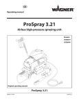
Airless – Hochdruck Spritzgerät
Airless high-pressure spraying unit
Appareil de pulvérisation à haute
pression Airless
Apparecchio di verniciatura a spruzzo
Airless ad alta pressione
Super Finish 7000
Neu
2306118
08 / 2009
Betriebsanleitung
Operating manual
Mode d‘emploi
2
32
61
Istruzioni per l‘uso
92
Super Finish 7000
GB
WARNING!
Attention, danger of injury by injection!
Airless units develop extremely high spray pressures.
1
Never bring fingers, hands or other body parts into contact with the spray jet!
Never point the spray gun at yourself, other persons or animals.
Never use the spray gun without spray jet safety guard.
Do not treat a spray injury as a harmless cut. In case of injury to the skin by coating material
or solvents, consult a doctor for quick and correct treatment. Inform the doctor about the
coating material or solvent used.
2
3
The following points are to be observed in accordance with the operating manual
before every start-up:
1. Faulty units may not be used.
2. Secure a Wagner spray gun with the securing lever at the trigger guard.
3. Ensure earthing.
4. Check the permissible operating pressure of the high-pressure hose and spray gun.
5. Check all the connecting parts for leaks.
Instructions for regular cleaning and maintenance of the unit are to be observed
strictly.
Observe the following rules before any work on the unit and at every working
break:
1. Relieve the pressure from the spray gun and high-pressure hose.
2. Secure a Wagner spray gun with the securing lever at the trigger guard
3. Switch the unit off.
Ensure safety!
32
Super Finish 7000
GB
Contents
Contents
4.3
4.4
1
1.1
1.2
1.3
4.5
1.4
1.5
1.6
1.7
1.8
1.9
1.10
1.11
1.12
1.13
1.14
1.15
1.16
1.17
1.18
1.19
1.20
1.21
1.22
1.23
Safety regulations for Airless spraying_34
Flash point__________________________________ 34
Explosion protection__________________________ 34
Danger of explosion and fire from sources of
ignition during spraying work_ _________________ 34
Danger of injury from the spray jet_ _____________ 34
Secure spray gun against unintended operation_ __ 34
Recoil of spray gun___________________________ 34
Breathing equipment as protection against
solvent vapors_______________________________ 34
Noise protection_____________________________ 34
Prevention of occupational illnesses_____________ 35
Max. operating pressure_______________________ 35
High-pressure hose (safety instructions)__________ 35
Electrostatic charging
(formation of sparks or flames) _________________ 35
Use of units on building sites and workshops______ 35
Ventilation when spraying in rooms_ ____________ 35
Suction installations__________________________ 35
Earthing of the object_________________________ 35
Cleaning the unit with solvents_________________ 35
Cleaning the unit_ ___________________________ 35
Work or repairs at the electrical equipment_ ______ 35
Work at electrical components__________________ 35
Working with a number of guns_________________ 35
Transport using a crane_ ______________________ 35
Setup on an uneven surface____________________ 36
2
2.1
2.2
2.2.1
General view of application_____________
Application_ ________________________________
Coating material_____________________________
Coating materials with sharp-edged additional
materials_ __________________________________
2.2.2 Filtering____________________________________
36
36
36
3.Description of unit_ _____________________
3.1 Airless process_______________________________
3.2 Functioning of the unit________________________
3.3 Explanatory diagram__________________________
3.4 Transportation_______________________________
3.5 Transport using a crane_ ______________________
3.6 Technical data Super Finish 7000________________
37
37
37
38
38
39
39
4
4.1
4.2
36
36
Startup_ _________________________________ 40
Unit with suction system_ _____________________ 40
High pressure hose and spray gun_______________ 40
4.6
Connection to the mains network_______________
Cleaning preserving agent when starting-up of
operation initially_ ___________________________
Ventilate unit (hydraulic system) if the sound of
inlet valve is not audible_______________________
Taking the unit into operation with
coating material_ ____________________________
41
41
41
41
5
Spraying technology_ ___________________ 42
6
6.1
Handling the high-pressure hose________ 42
High-pressure hose___________________________ 42
7
Interruption of work____________________ 42
8Cleaning the unit_ _______________________
8.1 Cleaning the unit from the outside_ _____________
8.2 Suction filter_ _______________________________
8.3 High-pressure filter___________________________
8.4 Cleaning the Airless spray gun__________________
43
44
44
44
45
9
9.1
9.2
Servicing_________________________________ 45
General servicing_ ___________________________ 45
High-pressure hose___________________________ 45
10
10.1
10.2
10.3
10.4
10.5
10.6
10.7
10.8
10.9
10.10
Repairs at the unit_ ______________________
Inlet valve Pusher_ ___________________________
Inlet valve_ _________________________________
Outlet valve_________________________________
Pressure control valve_________________________
Relief valve_ ________________________________
Replacing the diaphragm______________________
Replacing the power cable _ ___________________
Typical wear parts____________________________
Connection diagram__________________________
Remedy in case of faults_______________________
45
45
46
46
47
47
47
48
48
49
51
11
11.1
11.2
11.3
11.4
11.5
11.6
11.7
Spare parts and accessories_____________
Super Finish 7000 accessories_ _________________
Spare parts list Pump head _ ___________________
Spare parts list Pump-Aggregate _ ______________
Spare parts list high-pressure filter ______________
Spare parts List Trolley_ _______________________
Spare parts list suction system (rigid) ____________
Spare parts list hopper ________________________
52
52
54
55
57
57
58
58
Testing of the unit_ ________________________________ 59
Important information on product liability_____________ 59
Note on disposal___________________________________ 59
Guarantee declaration______________________________ 59
CE - declaration__________________________________ 123
European service network__________________________ 124
33
Super Finish 7000
GB
Safety regulations
1
Safety regulations for
Airless spraying
1.4
Attention, danger of injury by injection!
Never point the spray gun at yourself, other
persons or animals.
Never use the spray gun without spray jet
safety guard.
The spray jet must not come into contact
with any part of the body.
In working with Airless spray guns, the high
spray pressures arising can cause very dangerous injuries. If contact is made with the
spray jet, coating material can be injected
into the skin. Do not treat a spray injury as a
harmless cut. In case of injury to the skin by
coating material or solvents, consult a doctor
for quick and correct treatment. Inform the
doctor about the coating material or solvent
used.
The safety-specific requirements for Airless spraying are specified in:
a) The European Standard „Spray equipment for coating materials – safety regulations „ (EN 1953: 1998).
b) The regulations of the German employer‘s liability insurance association („Berufsgenossenschaft“) „Using liquid
jets“ (BGV D15) and „Processing coating materials „ (BGV
D25).
c) Guidelines for construction and implementation requirements for liquid jets (spraying units) of the German industrial employer‘s liability insurance association (ZH1/406).
The following safety regulations are to be observed in order
to ensure safe handling of the Airless high-pressure spraying
unit.
1.5
1.1
Flash point
Only spray coating materials with a flash point
of 21 °C or higher.
The flash point is the lowest temperature at
which vapors develop from the coating material. These vapors are sufficient to form an
inflammable mixture over the air above the
coating material.
1.2
Explosion protection
Do not use the unit in work places which are
covered by the explosion protection regulations.
The unit is not designed to be explosion protected.
1.3
Danger of explosion and fire from
sources of ignition during spraying
work
There must be no sources of ignition such as,
for example, open fires, lit cigarettes, cigars or
tobacco pipes, sparks, glowing wires, hot surfaces, etc. in the vicinity.
34
Danger of injury from the spray jet
Secure spray gun against unintended
operation
Always secure the spray gun when mounting or dismounting
the tip and in case of interruption to work.
1.6
Recoil of spray gun
When using a high operating pressure, pulling the trigger guard can effect a recoil force
up to 15 N.
If you are not prepared for this, your hand can
be thrust backwards or your balance lost. This
can lead to injury.
1.7
Breathing equipment as protection
against solvent vapors
Wear breathing equipment during spraying work.
A breathing mask is to be made available to the user (regulations of the German employer‘s liability insurance association („Berufsgenossenschaft“) „Rules for the use of breathing
masks“ (BGR 190), „Using liquid jets“ (BGV D15) and „Processing coating materials „ (BGV D25).
1.8
Noise Protection
Wear suitable ear protection when working.
Super Finish 7000
GB
Safety regulations
1.9
Prevention of occupational illnesses
1.15
Suction installations
Protective clothing, gloves and possibly skin protection cream
are necessary for the protection of the skin.
The are to be provided by the unit user in accordance with the
corresponding local regulations.
Observe the regulations of the manufacturer concerning coating materials, solvents and cleaning agents in preparation,
processing and cleaning units.
1.16
1.10
Max. operating pressure
The permissible operating pressure for the spray gun, spray
gun accessories, unit accessories and high-pressure hose
must not fall short of the maximum operating pressure of 25
MPa (250 bar or 3625 psi).
1.11
The object to be coated must be earthed.
(Building walls are usually earthed naturally)
1.17
1.18
Electrostatic charging (formation of
sparks or flames)
Electrostatic charging of the unit may occur
during spraying due to the flow speed of
the coating material. These can cause sparks
and flames upon discharge. The unit must
therefore always be earthed via the electrical
system. The unit must be connected to an
appropriately-grounded safety outlet.
1.13
Use of units on building sites and
workshops
1.19
Ventilation when spraying in rooms
Adequate ventilation to ensure removal of the solvent vapors
has to be ensured.
Work or repairs at the electrical
equipment
These may only be carried out by a skilled electrician. No liability is assumed for incorrect installation.
1.20
Work at electrical components
Unplug the power plug from the outlet before carrying out
any repair work.
1.21
Working with a number of guns
Changes to the device will affect all connected guns.
Sudden pressure increases (activation/modification) can cause accidents.
Make sure that you know the status of all
connected spray guns/accessories and inform all other users if necessary.
The unit may only be connected to the mains network via a
special feeding point with a residual-current device with INF
≤ 30 mA.
In the 400 volt version, a CEE 16A-6h socket with appropriate
fusing must be used for connection to the mains supply.
1.14
Cleaning the unit
Danger of short-circuits caused by water ingression!
Never spray down the unit with high-pressure or high-pressure steam cleaners.
Only use WAGNER original-high-pressure
hoses in order to ensure functionality, safety
and durability.
1.12
Cleaning the unit with solvents
When cleaning the unit with solvents, the
solvent should never be sprayed or pumped
back into a container with a small opening
(bunghole). An explosive gas/air mixture can
arise. The container must be earthed.
High-pressure hose (safety
instructions)
An electrostatic charging of spray guns and the high-pressure
hose is discharged through the high-pressure hose. For this
reason the electric resistance between the connections of the
high-pressure hose must be equal to or lower than 1 MΩ.
Earthing of the object
1.22
TRANSPORT USING A CRANE
Do not suspend the device using the extendable shaft.
35
Super Finish 7000
GB
Safety regulations
1.23
Setup on an uneven surface
The front end must always point downwards in order to avoid
sliding away.
2.2
Coating material
Dispersion and latex paints, two-component coating materials, diluting lacquers and paints or those containing solvents.
No other materials should be used for spraying without
WAGNER‘s approval.
Pay attention to the Airless quality of the coating materials to be processed.
The unit is able to process coating materials with up to
15,000 mPas. If highly viscous coating materials cannot be taken in or the performance of the unit is to low, the paint must
be diluted in accordance with the manufacturer‘s instructions.
Multi-gun operation is not possible when
working with high viscosity coating materials.
Stir coating substance well before commencing work.
If possible do not use the unit on an inclined surface since the
unit tends to wander through the resulting vibrations.
2
2.1
General view of application
Application
Super Finish 7000 is an electric driven unit for the airless atomization of different painting materials. Also it is able to feed
the internal feeded paint roller, which is available as accessory.
The performance of the Super Finish 7000 is designed to enable processing of dispersions for large objects both indoors
and outdoors (e.g. ceilings, facades, underground garages,
etc.). The use of corrosion protection and fire protection is also
possible.
The unit is able for all common varnishing jobs like
doors, door frames, balustrades, furniture, woodencladding,
fences, radiators (heating) and steel parts.
The device is prepared for operation with several guns. However, this requires appropriate accessories, which are available
separately.
36
Attention: Make sure, when stirring up with
motor-driven agitators that no air bubbles
are stirred in. Air bubbles disturb when spraying and can, in fact, lead to interruption of
operation.
2.2.1
Coating materials with sharp-edged
additional materials
These particles have a strong wear and tear effect on valves
and tips, but also on the heating hose and spray gun. This impairs the durability of these wearing parts considerably.
2.2.2
Filtering
Sufficient filtering is required for fault-free operation. To this
purpose the unit is equipped with a suction filter (Item 1) and
an insertion filter in the spray gun (Item 2). Regular inspection
of these filters for damage or soiling is urgently recommended.
A high-pressure filter (Item 3) -available as accessory- is rising
up the filtering surface and will make the work more comfortable.
Super Finish 7000
GB
General view of application
3.2
2
3
1
Functioning of the unit
The following section contains a brief description of the technical construction for better understanding of the function:
Super Finish 7000 is an electrically driven high-pressure paint
spraying equipment.
The motor (Item 1) drives directly the hydraulic pump.
A piston (2) is moved up and down so that hydraulic oil is
moved under the diaphragm (3) which then moves.
In detail:
The downwards movement of the machine opens the disk inlet valve (4) automatically and coating material is sucked in.
During the upwards movement of the diaphragm, the coating
material is displaced and the outlet valve (5) opens while the
inlet valve is closed.
The coating material flows under high pressure through the
high-pressure hose to the spray gun and is atomized when it
exists from the tip.
3.
3.1
Description of unit
Airless process
The pressure control valve (6) limits the set pressure in the
hydraulic oil circuit and thus also the pressure of the coating
material.
A pressure change when the same tip is used also leads to a
change in the amount of paint atomized.
6 5 3
4
The main area of application are thick layers of highly viscous
coating material.
At the Super Finish 7000 unit a diaphragm pump takes in the
coating materials and transports it via a high-pressure hose
to the spray gun with the airless tip. Here the coating material
atomizes since it is pressed through the tip core at a maximum
pressure of 25 MPa (250 bar, 3625 psi). This high pressure has
the effect of micro fine atomisation of the coating material.
As no air is used in this process, it is described as an AIRLESS
process.
This method of spraying has the advantages of finest atomisation, cloudless operation (depending of a correct unit adjustment) and a smooth, bubblefree surface. As well as these, the
advantages of the speed of work and convenience must be
mentioned.
2
1
37
Super Finish 7000
GB
Description of unit
3.3
Explanatory diagram
1
2
3
4
5
6
7
Tip guard with airless tip
Spray gun
High-pressure hose
Connection for high-pressure hose
Pressure gauge
Pressure control valve
Pressure relief valve
Symbols:
8
9
10
11
12
13
14
15
16
Spraying
2
3
Circulation
ON / OFF switch
Indicating lamp (green indicates presence of line voltage)
Return hose
Suction system
Inlet valve button
Outlet valve
Oil measuring stick under the oil screw plug
Inlet filter
Storage container for flexible suction system (Accessory.
Not included in the scope of supply.)
3.4
1
6
4
5
14
Transportation
Device is very heavy (60 kg).
Only lift or carry the device in pairs.
Roll up the high-pressure hose and place over the carriage
frame.
Pull out the shaft.
Push or pull the device.
To retract the shaft, hold both buttons (1) pressed down.
1
16
13
7
12
8
9
10
11
Transportation in vehicle
Secure the unit in the vehicle by means of suitable fasteners.
The device can be placed on its side if necessary. In this case,
please ensure that no attachments can be damaged. Attention: Paint or solvent residues can escape from the connections!
38
15
Super Finish 7000
GB
Description of unit
3.5
TRANSPORT USING A CRANE
For attaching points for the straps or rope (not wire cable) see
figure.
3.6
Technical data Super Finish 7000
Article no. basic unit
2305973
2306248
Voltage :
230 Volt ~,
50 Hz
400 Volt ~,
50 Hz
Fuses :
16 A time-lag
16 A
Unit connecting line :
6 m long,
3x1.5 mm²
6 m long,
5x1.5 mm²
Max. current consumption
hose heating :
13.5 A
5.8 A
Degree of protection :
IP 44
IP 44
Acceptance capacity :
2.8 kW
3.1 kW
Max. operating pressure :
25 MPa
(250 bar)
25 MPa
(250 bar)
Max. volume flow :
7.2 l/min
7.2 l/min
Volume flow at 12 MPa
(120 bar) with water :
5.8 l/min
5.8 l/min
Max. temperature of the
coating material :
43 °C
43 °C
Max. viscosity :
15 000 mPas
15 000 mPas
Empty weight pump :
60 kg
60 kg
Hydraulic oil filling quantity: 1.5 litre
1.5 litre
Max. vibration at the spray
gun :
lower than
2.5 m/s²
lower than
2.5 m/s²
Max. sound pressure level:
82 dB (A)*
82 dB (A)*
*Place of measurement: 1 m distance from unit and 1.60 m
above floor, 12 Mpa (120 bar) operating pressure, reverberant
floor
Do not suspend the device using the extendable shaft.
39
Super Finish 7000
GB
Startup
4
4.2
Startup
4.1
Unit with suction system
1. Unscrew the dust protective cap (Item 1).
2. Ensure that the sealing surfaces of the connections are
clean.
Ensure that the red inlet (2) is inserted in the coating material inlet (5).
3. If using the suction system
Screw union nut (3) on suction system (4) to the coating
substance inlet (5) with the spanner provided (41mm) and
fasten finger-tight.
If using the upper container (accessories)
Screw container adapter (12) to coating substance inlet
(5) and fasten finger-tight. Place upper container (9) on
container adapter (12) and align. Place return hose (7) in
upper container.
4. Screw the union nut (6) at the return hose (7) to the connection (8) (22mm).
high pressure hose and spray gun
A special adapter is required for operation
with several guns (see accessories). Several
adapters can be connected together, so that
two additional guns can be used per adapter.
Multi-gun operation is not possible when
working with high viscosity coating materials.
1. Screw adapter for multiple-gun operation to hose connection (if required).
2. Screw the high pressure hose (10) onto the hose connection or the adapter.
Unused connections on the adapter must be
sealed with the protective caps provided.
Only connect as many hoses as will be used.
All connected hoses are pressurised!
3. Screw the spray gun (11) onto the high pressure hose
4. Tighten all union nuts on high pressure hose so that no
coating material can escape.
5. Screw the tip holder with the selected tip onto the spray
gun, align tip and tighten union nut.
When unscrewing the high pressure hose,
hold firmly on the hose connection with a
22mm wrench.
8
11
2
5
6
3
4
7
40
1
7
9
10
6
12
5
8
Super Finish 7000
GB
Startup
4.3
Connection to the mains network
Connection must always be carried out via
an appropriately grounded safety outlet with
residual-current-operated circuit-breaker.
3
1
Before connecting the unit to the mains supply, ensure that
the line voltage matches that specified on the unit’s rating
plate.
4.4
Cleaning preserving agent when
starting-up of operation initially
1. Immerse the suction system into a container filled with a
suitable cleaning agent (recommendation: water).
2. Switch on unit.
3. Turn the pressure regulating knob (1) to the right until
the stop is reached.
4. Open relief valve (2)
valve position
(circulation)
5. Wait until cleaning agent is emitted from the return hose.
6. Turn the pressure regulating knob (1) back approx. one
rotation.
7. Close relief valve (2)
valve position
(spraying), pressure is rising up inside
the high pressure hose (visible at pressure gauge)
8. Point the tip of the spray gun into an open collecting container and pull the trigger guard at the spray gun.
9. The pressure is increased by turning the pressure regulating knob (1) to the right. Set approx. 10 MPa at the pressure gauge.
10. Spray the cleaning agent out of the unit for approx.
1 - 2 min. (~5 litres) into the open collecting container.
4.5
Ventilate unit (hydraulic system) if the
sound of inlet valve is not audible
1. Switch on the unit.
2. Turn pressure regulating knob (1) three revolutions to
the left.
3. Open relief valve (2)
valve position
(circulation)
The hydraulic system is ventilated. Leave the unit on for
two or three minutes.
4. Then turn pressure regulating knob (1) to the right until
stop.
5. Press inlet valve pusher (4).
Sound of the inlet valve is audible.
6. If not, repeat points 2 and 4
4
2
4.6
Taking the unit into operation with
coating material
1. Immerse the suction system into a container filled with
coating material.
2. Press inlet valve pusher (4) several times to release possibly clogged inlet valve
3. Open relief valve (2)
valve position
(circulation)
4. Switch on unit.
5. Turn the pressure regulating knob (1) to the right until
the stop is reached.
When the noise of the valves changes, the unit is bled and
takes in coating material.
6. If coating material exits from the return hose, turn the
pressure regulating knob (1) back approx. 1 rotation.
7. Close relief valve (2)
valve position
(spraying), pressure is rising up inside
the high pressure hose (visible at pressure gauge)
8. Pull of the spray gun and spray into an open collecting
container in order to remove the remaining cleaning
agent from the unit. When coating materials exits from
the tip, close the spray gun.
9. Pull of the spray gun and adjust the spraying pressure by
turning the pressure regulating knob (1).
10. The unit is ready to spray.
41
Super Finish 7000
GB
Spraying technique / Handling the high-pressure hose / Interruption of work
5
Spraying technology
Move the spray gun evenly during the spraying process. If this
is not observed, an irregular spraying appearance will be the
result. Carry out the movement with the arm, not with the
wrist. A parallel distance of approx. 30 cm between the tip and
the surface to be coated should always be observed. The lateral limitation of the spray fan should not to be too distinct.
The edge of spraying should be gradual to facilitate overlapping of the next coat. The spray gun should always be held at
an angle of 90° to the surface to be coated. A spray fan aimed
obliquely at the surface to be coated leads to an unwanted
spray cloud.
Depending on the material, the use of a
smaller nozzle size or fewer guns can improve the spray pattern when using multiplegun operation.
To achieve perfect surfaces at varnishing works, special accessories are available at Wagner, e.g. FineFinish tips or an AirCoat
gun set. Your Wagner dealer will advise you.
6
Handling the high-pressure
hose
The high-pressure hose is to be handled with care. Avoid sharp
bending or kinking. The smallest bending radius amounts to
about 20 cm.
Do not drive over the high-pressure hose. Protect against
sharp objects and edges.
Danger of injury through leaking highpressure hose. Replace any damaged highpressure hose immediately.
Never repair defective high-pressure hoses
yourself!
When using the high-pressure hose while
working on scaffolding, it is best to always
guide the hose along the outside of the scaffolding.
6.1
High-pressure hose
The unit is equipped with a high-pressure hose specially suited for diaphragm pumps.
Only use WAGNER original-high-pressure
hoses with internal heating in order to ensure
functionality, safety and durability.
Longer hoses (30 m is optimal) reduce vibrations.
42
7
Interruption of work
1. Turn pressure regulating knob three revolutions to the
left.
2 Open relief valve (2)
valve position
(circulation)
3. Switch off the unit
4. Pull the trigger guard on all spray guns in order to safely relieve the pressure of high-pressure hoses and spray
guns.
5. Secure the spray gun, refer to the operating manual of the
spray gun.
6. Remove tip from tip holder and store the tip in a small vessel with suitable cleaning agent.
7. Leave the suction system immersed in the coating material or immerse it in the corresponding cleaning agent.
The suction filter and unit should not dry out.
8. Cover the material container in order to prevent the paint
from drying.
When using quick-drying or two-component
coating substances, always flush the device
through with a suitable cleaning agent within the processing time, as otherwise it will be
difficult to clean.
Super Finish 7000
GB
Displays at the unit / Cleaning the unit
8
Cleaning the unit
A clean state is the best method of ensuring operation without problems. After you have finished spraying, clean the unit.
Under no circumstances may coating material rests dry and
harden in the unit. The cleaning agent used for cleaning (only
with a flash point above 21 °C) must be suitable for the coating material used.
•
1.
2.
3.
4.
5.
6.
Secure the spray gun, refer to the operating manual of
the spray gun.
Remove and clean the tip and tip guard.
Open relief valve
valve position
(circulation) and switch on unit
Remove suction system from the material container. The return tube remains over the material container.
Immerse the suction system into a container filled with a
suitable cleaning agent
Turn the pressure control valve back in order to set a minimal spraying pressure.
Close relief valve,
valve position
(spraying)
Pull the trigger guard of the spray gun in order to pump the
remaining coating material from the suction hose, highpressure hose and the spray gun into an open container
(if appropriate, increase the pressure at the pressure control valve slowly in order to obtain a higher material flow).
When using multiple-gun operation the trigger guards
must be pulled in succession, in order to increase the
cleaning performance.
The container must be earthed in case of
coating materials which contain solvents.
Caution! Do not pump or spray in container
with small opening (bunghole)!
See safety regulations.
7. Open relief valve
valve position
(circulation)
8. Pump suitable cleaning agent in the circuit for several
minutes.
Suction system with Quick Clean (points 9 to 17)
9. Screw the spray gun to the suction tube with both enclosed 22 mm wrenches.
10. Pump a suitable cleaning agent in the circuit for about
1 minute.
11. Pull the trigger guard of the spray gun and lock it with a
clamp.
12. Close relief valve,
valve position
(spraying)
13. Clean the suction tube about 3 minutes long.
14. Rinse in the circuit – Open relief valve
valve position
(circulation).
15. Close the spry gun.
16. When cleaning with water repeat the procedure about 3
minutes long with clear water.
17. Remove spray gun from suction tube, close spray gun
connection at suction tube with closure nut.
The cleaning effect is increased by alternatively opening and closing the spray gun.
18. Close relief valve,
valve position
(spraying)
19. Pump the remaining cleaning agent into an open container until the pump is empty.
20. Switch off the unit
Warm water improves the cleaning effect in
the case of water-dilutable coating materials.
Unit with upper hopper
1. Open relief valve
valve position
(circulation) and switch on unit
2. Turn the pressure control valve back in order to set a minimal spraying pressure.
3. Close relief valve,
valve position
(spraying)
4. Pull the trigger guard of the spray gun in order to pump
the remaining coating material from the hopper, highpressure hose and the spray gun into an open container (if
appropriate, increase the pressure at the pressure control
valve slowly in order to obtain a higher material flow).
43
Super Finish 7000
GB
Cleaning the unit
The container must be earthed in case of
coating materials which contain solvents.
Device with flexible suction
system (accessory)
1. Unscrew the filter (Item 1)
from the suction tube (2).
2. Disassemble filter by rotating the base (3).
3. Clean or replace the filter.
Carry out cleaning with
a hard brush and a corresponding cleaning agent.
2
Caution! Do not pump or spray in container
with small opening (bunghole)!
See safty regulations.
5.
6.
7.
Fill up hopper with suitable cleaning agent.
Open relief valve
valve position
(circulation)
Pump suitable cleaning agent in the circuit for several minutes.
8. Close relief valve,
valve position
(spraying)
9. Pump the remaining cleaning agent from the hopper,
high-pressure hose and the spray gun into an open container
10. Open relief valve
valve position
(circulation)
11. Switch off unit
8.1
Cleaning the unit from the outside
First unplug the power plug from the outlet.
Danger of short-circuits caused by water
ingression! Never spray down the unit with
high-pressure or high-pressure steam cleaners.
The suction hose is only solvent-resistant to
a limited extent. Do not immerse in solvent,
only wipe.
Wipe down unit externally with a cloth which has been immersed in a suitable cleaning agent.
8.2
Suction filter
Clean filters always ensure maximum volume,
constant spray pressure and problem-free
functioning of the unit.
Device with rigid suction system
1. Unscrew the filter (Item 1) from
the suction tube.
2. Clean or replace the filter.
Carry out cleaning with a hard
brush and a corresponding cleaning agent.
1
44
1
3
Unit with hopper
1. Release screws with a screwdriver.
2. Lift and remove filter disk with a screwdriver
3. Clean or replace the filter disk.
Carry out cleaning with a hard brush and a corresponding
cleaning agent.
8.3
High-pressure filter
1. Open relief valve
valve position
(circulation) - Switch the unit off.
2. Open the high-pressure filter and clean the filter insert. To
do so:
3. Unscrew the filter housing (1) by hand.
4. Remove the filter insert (2) and pull out the bearing spring
(3).
5. Clean all the parts with the corresponding cleaning agent.
If compressed air is available – blow through the filter insert and bearing spring.
6. When mounting the filter ensure that the bearing ring (4)
in the filter insert is positioned correctly and check the Oring at the filter housing for damage.
7. Screw on the filter housing by hand until it stops (a higher
tightening force only impedes later dismantling).
Super Finish 7000
GB
Cleaning the unit / Servicing
8.4
Cleaning the Airless spray gun
1. Rinse the Airless spray gun with a suitable cleaning agent
under lower operating pressure.
2. Clean the tip thoroughly with a suitable cleaning agent
so that no suitable coating material rests remain.
Do not use sharp objects to clean the nozzle.
3. Clean the outside of the Airless spray gun thoroughly.
9
9.1
Servicing
General servicing
An annual expert check is highly recommended to be sure to have a safe unit.
You can servicing of the unit carried out by
the Wagner Service. Favourable conditions
can be agreed with a service agreement and/
or maintenance packages.
Change hydraulic oil every 300 operating
hours or at least once a year.
1
3
2
Minimum check before every startup:
1. Check the high-pressure hose, spray gun with rotary joint,
power supply cable with plug for damage.
2. Check whether the pressure gauge can be read.
Check at periodical intervals:
1. Check inlet-, outlet-, relief valve according wear. Clean it
and replace worn out parts.
2. Check all filter inserts (spray gun, suction system) clean it
and replace if necessary.
9.2
Insertion filter in Airless spray gun
Removal
1. Pull the protective bracket (1) forwards.
2. Screw the grip (2) out of the gun housing. Pull out the insertion filter (3).
3. If the insertion filter is clogged or defective, replace it.
Installation
1. Slide the insertion filter (3) with the longer cone into the
gun housing.
2. Screw the grip (2) into the gun housing and tighten it.
3. Latch in the protective bracket (1).
High-pressure hose
Inspect the high-pressure hose visually for any notches or
bulges, in particular at the transition in the fittings. It must be
possible to turn the union nuts freely. A conductivity of less
than 1 MΩ must exist across the entire length.
Have all the electric tests carried by the Wagner Service.
10
Repairs at the unit
Switch the unit off.
Before all repair work: Unplug the power
plug from the outlet.
10.1
Inlet valve Pusher
1. Use a 17 mm spanner to screw out the inlet valve button.
2. Replace the wiper (1) and O-ring (2).
45
Super Finish 7000
GB
Repairs at the unit
1
2
1
3
5
2
4
6
10.2
Inlet valve
1. Place the enclosed 30 mm wrench on the trigger housing
(1).
2. Loosen the trigger housing (1) with light blows of a hammer on the end of the wrench.
3. Screw out the trigger housing with the inlet valve (2) from
the paint section.
4. Pull of the clasp (3) using the enclosed screwdriver.
5. Place the enclosed 30 mm wrench on the inlet valve (2).
Turn out the inlet valve carefully.
6. Clean the valve seat (4) with a cleaning agent and brush
(ensure that no brush hairs are left behind).
7. Clean the seals (5, 6) and check for damage. Replace, if
necessary.
8. Check all the valve parts for damage. In case of visible
wear replace the inlet valve.
Installation
1. Insert the inlet valve (2) into the trigger housing (1) and
secure with the clasp (3). Ensure that the (black) seal (5) is
mounted in the trigger housing.
2. Screw the unit from the trigger housing and the inlet valve
into the paint section. The white seal (6) must be fitted in
the colour stage.
3. Tighten the trigger housing with the 30 mm wrench and
tighten with three light blows of the hammer on the end
of the wrench. (Corresponds to approx. 90 Nm tightening
torque).
46
10.3
Outlet valve
1. Use a 22 mm wrench to screw the outlet valve from the
paint section.
2. Carefully pull of the clasp (1) using the enclosed screwdriver. The compression spring (2) presses ball (4) and
valve seat (5) out.
3. Clean or replace the components.
4. Check the O-ring (7) for damage.
5. Check the installation position when mounting the spring
support ring (3) (clipped onto spring (2)), outlet valve seat
(5) and seal (6), refer to figure.
1
6 5
4 3
2
7
Super Finish 7000
GB
Repairs at the unit
10.4
Pressure control valve
Only have the pressure control valve (1) replaced by the customer service.
The max. operating pressure has to be reset
by the customer service.
1. Screw the trigger housing with inlet valve out of the paint
section as described in Section 10.2 Inlet valve, Items 1 to
3. (disassembling of hexagon nuts will become easier)
2. Turn back the pressure control valve, rotary knob completely (anti-clockwise).
(Note: If the unit is still warm, open the oil screw plug (6)
briefly in order to compensate the pressure and close it
again.)
3. Use a 19 mm wrench to screw the hexagonal bolt (Item 1)
out of the flange ring (2).
4. Remove the paint section (3).
5. Remove the insert (4) and the diaphragm (5).
6. The diaphragm can only be used once. Always replace the
diaphragm.
1
1
3
10.5
Relief valve
Replace a fault relief valve (1) as a single unit.
Only the O-ring (2) may be replaced as a single part
4
5
2
6
2
1
10.6
Replacing the diaphragm
Switch the unit off.
Before all repair work: Unplug the power
plug from the outlet.
47
Super Finish 7000
GB
Repairs at the unit
Before mounting the new diaphragm, clean the insert as well
as the grooved surface at the pressure insert (2) and the paint
section (3) and wipe off any oil.
4
1
Mounting is carried out in the reverse order.
1. First tighten all the hexagonal bolts (1) crosswise with
30Nm, then crosswise with 70Nm.
2. Before starting up leave the pressure control valve in the
open position for about 2 minutes while the motor is running (bleeds the unit). Only then close it until the noise of
the inlet valve can be heard.
10.7
Replacing the power cable
Work or repairs at the electrical equipment
may only be carried out by a skilled electrician. No liability is assumed for incorrect installation.
Switch the unit off.
Before all repair work: Unplug the power
plug from the outlet.
Representation of
230 V version
2
3
1. Dismount the cover (1) by loosening the 6 recessed-head
screws (4).
2. Loosen the cable threaded joint (2).
3. Loosen the wires in the mains terminal (3) .
4. Replace the unit connecting line.
(only an approved power cable with the designation H07RNF with a splash-proof plug may be used).
5. Connect the green/yellow wire to the contact with the PE
sign.
6. Connect the cover again and mount it carefully (do not
squeeze any cables!)
10.8
Typical wear parts
Despite the use of high-quality materials the highly abrasive
effect of the paints means that wear can occur at the following parts:
Inlet valve (spare part Order No.: 0254 524)
For replacing refer to Section 10.2
(failure becomes noticeable through performance loss and/or
poor or no suction)
Outlet valve (spare part Order No.: 0341702)
For replacing refer to Section 10.3
(failure becomes noticeable through performance loss and/
or poor suction) The outlet valve is usually considerably more
durable than the inlet valve. Thorough cleaning may already
help here.
Relief valve (spare part Order No.: 0169248)
For replacing refer to Section 10.5
(failure is noticeable through performance loss. Furthermore
material arrives constantly at the return hose although the
multifunction switch is set to spraying.
This part is relatively seldom a wear part.
48
Representation of
400 V version
2
3
Super Finish 7000
GB
Repairs at the unit
10.9
Connection diagram (230 Volt Version)
49
GB
Repairs at the unit
Connection diagram (400 Volt Version)
50
Super Finish 7000
Super Finish 7000
GB
Repairs at the unit
10.10
Remedy in case of faults
Type of malfunction
What else?
Possible cause
Measures for eliminating the malfunction
Unit does not start
Motor switch can not
switched on
Indicating lamp does
not illuminate
No voltage applied
Check voltage supply
400V version
N (neutral) conductor not
connected
Have mains connection checked by a skilled
electrician
Motor switch can not
switched on
Indicating lamp illuminates
Unit fuse has triggered
Let the motor cool down
400V version
Motor hums
Lines missing or interrupted
Have mains connection checked by a skilled
electrician
Air bubbles exit from
the return hose
Unit is sucking in outside
air
Check: Suction system tightened properly?
Inlet valve button leaky? -> Replace wiper and
O-ring (-> refer to Section 10.1)
Unit does not suck in
Air bubbles do not exit Inlet valve clogged
at the return hose
Unit does not generate pressure
Press the inlet valve button until the stop is
reached several times by hand
Inlet/outlet valve soiled
/ foreign bodies (e.g.
threads) drawn in / worn
Remove the valves and clean then (-> refer to
Section Pkt.10.2/10.3) / replace worn parts
Pressure control valve
turned down completely
Turn the pressure control valve to the right until the stop is reached
Unit has sucked in
Air in the oil circuit
Bleed the oil circuit in the unit by turning the
pressure control valve completely to the left
(until overturning) and let it run approx. 2 – 3
min. Then turn the pressure control valve to
the right and set the spraying pressure (repeat
process several times, if necessary).
Unit reached pressure, but the pressure
collapses, also at the
pressure gage, during
spraying.
Suction filter clogged
Check the suction filter. If necessary, clean/
replace
Paint cannot be worked in Dilute the paint
this state. Due to its properties the paint clogs the
valves (inlet valve) and the
delivery rate is too low.
Unit reached pressure, Clogged filter do not let
but the pressure colenough paint pass
lapses during spraying.
pressure gauge still
shows high pressure
Tip clogged
Unit does not generate Relief valve defective
the max. pressure possible. Paint nevertheless exits at the return
hose.
Poor spray pattern
During multiple-gun
operation
Check/clean the (high-pressure filter) gun filter
Clean the tip (-> refer to Section 8.4)
Clean or replace the relief valve (-> refer to
Section 10.5)
Tip clogged
Clean the tip (-> refer to Section 8.4)
Incorrect nozzle size
Use different nozzle size
Too many guns connected
Use fewer guns
51
Super Finish 7000
GB
Spare parts and accessories
11
11.1
Spare parts and accessories
order no.
1
Spray gun AG-14; 1/4“
(stainless steel)
Spray gun AG-08; 1/4“
(aluminium made)
0502 166
Insert filter red, 1 pc. ; 180 MA
Insert filter red, 10 pcs. ; 180 MA
Insert filter yellow, 1 pc.; 100 MA
Insert filter yellow, 10 pcs.; 100 MA
Insert filter white, 1 pc.; 50 MA
Insert filter white, 10 pcs.; 50 MA
Insert filter green, 1 pc.; 30 MA
Insert filter green, 10 pcs.; 30 MA
0034 383
0097 022
0043 235
0097 023
0034 377
0097 024
0089 323
0097 025
3
HP hose DN-3; 7.5m; 1/4“
HP hose DN-8; 15m; 1/4“
HP hose DN-10; 15m; 3/8“
HP hose DN-13; 15m; 1/2“
9984 583
9984 582
9984 506
9984 568
4
Inline Roller
0345 010
5
Tip extension
Length 15 cm
Length 30 cm
Length 45 cm
Length 60 cm
0556 051
0556 052
0556 053
0556 054
6
Tip extension with
Slewable knee joint
Length 100 cm
Length 200 cm
Length 300 cm
0096 015
0096 016
0096 017
7
Suction system (flexible) complete
0034 630
8
Inlet filter
0036 580
9
Storage container for flexible suction system, complete with mounting parts
2306 366
10
Upper hopper fittings, 20 litres
0341 266
11
Suction system (rigid) for dispersions
0253 209
12
Double nipple with 2x60° 530bar
A= 3/8“x3/8“
Double nipple with 2x60°
A= 1/2“x1/2“
Reducing double nipple with 2x60°
A= 1/2“x3/8“
Reducing double nipple with 2x60°
530bar A= 3/8“x1/4“
Double nipple with 2x60°
A= 1/4“x1/4“
0256 343
13
Connecting piece cpl I=1/4“xA=3/8“
0179 732
14
Adapter for multiple-gun operation
230 4430
15
Pole gun 120cm; G thread 7/8”
Pole gun 120cm; F thread 11/16”
Pole gun 240cm; G thread 7/8”
Pole gun 240cm; F thread 11/16”
0296 441
0296443
0296442
0296444
Hose line
9984 458
52
7
Super Finish 7000 accessories
item designation
2
1
9
0296 388
2
8
3
10
11
4
12
5
13
3202 901
3203 026
6
0367 561
0034 038
15
I
A
14
Super Finish 7000
GB
Spare parts and accessories
without tip
F thread (11/16 - 16 UN)
for Wagner spray guns
Order no. 0556 042
62
1
Wagner
Professional tip
up to 270 bar
(27 MPa)
without tip
G thread (7/8 - 14 UN)
for Graco/Titan spray guns
Order no. 0556 041
62
1
Airless tip table
tip marking
Spray
angle
Bore
inch / mm
Spraying width mm 1) Order no.
Natural paints
clear paints
Oils
407
507
209
309
409
509
609
40°
50°
20°
30°
40°
50°
60°
0.007 / 0.18
0.007 / 0.18
0.009 / 0.23
0.009 / 0.23
0.009 / 0.23
0.009 / 0.23
0.009 / 0.23
160
190
145
160
190
205
220
0552 407
------------0552 209
0552 309
0552 409
0552 509
0552 609
111
211
311
411
511
611
10°
20°
30°
40°
50°
60°
0.011 / 0.28
0.011 / 0.28
0.011 / 0.28
0.011 / 0.28
0.011 / 0.28
0.011 / 0.28
85
95
125
195
215
265
0552 111
0552 211
0552 311
0552 411
0552 511
0552 611
113
213
313
413
513
613
813
10°
20°
30°
40°
50°
60°
80°
0.013 / 0.33
0.013 / 0.33
0.013 / 0.33
0.013 / 0.33
0.013 / 0.33
0.013 / 0.33
0.013 / 0.33
100
110
135
200
245
275
305
0552 113
0552 213
0552 313
0552 413
0552 513
0552 613
0552 813
115
215
315
415
515
615
715
815
10°
20°
30°
40°
50°
60°
70°
80°
0.015 / 0.38
0.015 / 0.38
0.015 / 0.38
0.015 / 0.38
0.015 / 0.38
0.015 / 0.38
0.015 / 0.38
0.015 / 0.38
90
100
160
200
245
265
290
325
0552 115
0552 215
0552 315
0552 415
0552 515
0552 615
0552 715
0552 815
217
317
417
517
617
717
219
319
419
519
619
719
819
20°
30°
40°
50°
60°
70°
20°
30°
40°
50°
60°
70°
80°
0.017 / 0.43
0.017 / 0.43
0.017 / 0.43
0.017 / 0.43
0.017 / 0.43
0.017 / 0.43
0.019 / 0.48
0.019 / 0.48
0.019 / 0.48
0.019 / 0.48
0.019 / 0.48
0.019 / 0.48
0.019 / 0.48
110
150
180
225
280
325
145
160
185
260
295
320
400
0552 217
0552 317
0552 417
0552 517
0552 617
0552 717
0552 219
0552 319
0552 419
0552 519
0552 619
0552 719
0552 819
221
421
521
621
821
20°
40°
50°
60°
80°
0.021 / 0.53
0.021 / 0.53
0.021 / 0.53
0.021 / 0.53
0.021 / 0.53
145
190
245
290
375
0552 221
0552 421
0552 521
0552 621
0552 821
223
423
523
623
723
823
20°
40°
50°
60°
70°
80°
0.023 / 0.58
0.023 / 0.58
0.023 / 0.58
0.023 / 0.58
0.023 / 0.58
0.023 / 0.58
155
180
245
275
325
345
0552 223
0552 423
0552 523
0552 623
0552 723
0552 823
225
425
525
625
825
227
427
527
627
827
629
231
431
531
631
433
235
435
535
635
839
20°
40°
50°
60°
80°
20°
40°
50°
60°
80°
60°
20°
40°
50°
60°
40°
20°
40°
50°
60°
80°
0.025 / 0.64
0.025 / 0.64
0.025 / 0.64
0.025 / 0.64
0.025 / 0.64
0.027 / 0.69
0.027 / 0.69
0.027 / 0.69
0.027 / 0.69
0.027 / 0.69
0.029 / 0.75
0.031 / 0.79
0.031 / 0.79
0.031 / 0.79
0.031 / 0.79
0.033 / 0.83
0.035 / 0.90
0.035 / 0.90
0.035 / 0.90
0.035 / 0.90
0.039 / 0.99
130
190
230
250
295
160
180
200
265
340
285
155
185
220
270
220
160
195
235
295
480
0552 225
0552 425
0552 525
0552 625
0552 825
0552 227
0552 427
0552 527
0552 627
0552 827
0552 629
0552 231
0552 431
0552 531
0552 631
0552 433
0552 235
0552 435
0552 535
0552 635
-------------
243
543
552
20°
50°
50°
0.043 / 1.10
0.043 / 1.10
0.052 / 1.30
185
340
350
0552 243
0552 543
0552 552
Paints, primers
zinc chromate base
Fillers
Spray gun filter "yellOW"
Synthetic-resin paints
PVc paints
Spray gun filter "Red"
Application
Fillers
Spray plasters
Rust protection paints
Mica paints
zinc dust paints
dispersions
Rust protection paints
Spray gun filter "WHIte"
Spray plasters
Rust protection paints
Red lead
latex paints
large-area coatings
Spray gun filter "GReeN"
dispersions
Binder, glue
and filler paints
1) Spray width at about 30 cm to the object and 100 bar (10 MPa) pressure with synthetic-resin paint 20 DIN seconds.
53
Super Finish 7000
GB
Spare parts and accessories
11.2
Spare parts list Pump head
item order-No
designation
1
0254 347
Paint head
2
0254 232
Diaphragm assy.
3
0341 314
Screw flange
4
9971 469
O-ring 35x2 (PTFE)
5
0341 315
Flange ring
6
0034 357
Pressure spring
7
0254 341
Insert, piston
8
0254 340
Piston D26
9
0254 230
Pressure insert assy.
10
9900 377
Cylinder head screw M8x 50 (4)
11
9920 102
Washer 8,4 (4)
12
9991 797
Manometer
13
9970 109
Sealing ring
14
0047 432
Double socket 1/4“ NPS/M16x1,5
15
9970 103
Sealing ring
16
0341 325
Valve guide
17
0341 702
Outlet valve, service set
18
0254 524
Inlet valve
19
0341 336
Clasp
20
9990 865
Dust protective cap
3
21
0340 339
Inlet
4
22
9971 486
O-ring 4x2 (FFPM)
5
23
0341 316
Wiper
6
24
0341 241
Inlet valve button
25
0252 279
Trigger housing
8
26
0341 331
Sealing ring
27
0341 330
Sealing ring
33
28
9900 217
Hexagon head screw M12x60 (6)
29
9920 204
Washer 13 (6)
30
9971 395
O-ring 10x1,25
31
0169 248
Relief valve (item. 30,31)
32
9971 365
O-ring 9,25x1,78
33
0252 294
Control valve assy. (item. 32,33)*
34
0010 859
Stop sleeve*
35
0010 861
Pressure spring*
36
0010 858
Clasp*
54
37
0341 219
Pressure regulating knob*
38
0341 599
Label
* When these parts are replaced the operating pressure has to
be set again by the customer service.
21
20
22
23
24
25
14
16
15
19
26
18
17
27
28
29
1
31
30
2
13
12
7
10
11
36
36
37 34 35
9
32
Spare parts diagram pump head
Super Finish 7000
GB
Spare parts and accessories
11.3
Spare parts list Pump-Aggregate
item ortder-No
designation
34
0254 335
Electric box
1
35
9900 249
Hex washer head screw
M5x12 (4)
36
9950 244
Terminal strip (230V version)
37
2306 244
Terminal strip (400V version)
0254 221
2
3050 814
Motor partition assembled 230V/50Hz
(item. 1,3, 4)
Motor partition assembled 400V/50Hz
(item. 1,3, 4)
Hexagon screw M6x25 (4)
3
0254 520
Fan
38
9902 234
Pan head screw ST 2,9x16 (1)
4
0254 521
Fan cowl
39
0254 334
Cover
5
Snap ring 82x2,5 DIN 471
Hydraulics housing (pos. 6 and 26)
40
9905 103
Pan head screw ST4,3x19 (6)
6
2301 762
2304 436
41
0254 346
Label SF 7000
7
3056 464
Snap ring 72x2,5 DIN 472
42
9902 228
8
9970 103
Sealing ring
Pan head screw 4,2 x 9,5 (2)
(400V version)
9
9904 302
Hexagon socket screw plugs
43
2306 174
Miniature contactor (400V version)
10
0254 516
Shaft sealing ring
44
9952 870
Capacitor 60µF (230V version)
11
0115 437
O-ring
45
9902 209
Pan head screw ST 3,9x25 (1)
12
0254 327
Bearing adaptor
46
9953 704
Motor protection switch
13
14
0254 515
0254 233
47
2301 766
Green glow lamp
15
9960 431
Bearing, cylinder roller
Bearing, eccentric assy.
(incl. item 15, 16)
Roller bearing
16
9922 603
Snap ring 52x2 DIN 472
17
0254 356
Oil line
18
0254 322
Cover seal
19
0254 321
Front cover assy.
20
9900 307
Cylinder head screw M5x16 (11)
21
0288 406
Hose clip
22
9900 377
Cylinder head screw M8x50 (4)
23
0341 348
Oil dipstick
24
9971 146
O-ring
25
0252 453
Oil cap screw
26
0190 370
Adapter
27
28
9971 315
0261 352
29
2306 340
30
9952 685
O-ring
Mains cable (230V version)
H07RN-F3G1,5 6m long
Mains cable (230V version)
H07RN-F5G 1,5 6m long; CEE 16A-6h
Cable threaded joint M20x1,5
31
0254 336
Seal
32
0254 337
Intermediate plate
33
9900 518
Hex. socket counters. head screw
M5x12 (4)
2306 246
55
56
Spare parts diagram pump-aggregate
14
15
17 16
18
20 19
21
25
24
23
26
27
28
7
11 10
13 12
29
9
8
7
22
30
35
34
33
32
31
39
38
37
36
40
6
5
1
2
3
47
46
45
42
43
44
41
4
GB
Super Finish 7000
Spare parts and accessories
Super Finish 7000
GB
Spare parts and accessories
11.4
Spare parts list high-pressure filter
(Accessory)
11.5
Spare parts List Trolley
Item Order No.
Designation
Item order-no.
Designation
1
0097 121
High-pressure filter HF- 01 compl.
1
0254 240
Trolley assy.
2
0097 301
Filter block
2
0348 349
Wheel (2)
3
0097 302
Filter housing
3
9994 902
Wheel cap (2)
4
0097 303
Hollow screw
4
0254 372
Handle leading
5
0097 304
Seal ring
5
0254 373
Axis
6
9970 110
Seal ring
6
0254 368
Plug, tube end
7
9974 027
O-ring 30x2 (PTFE)
7
0254 369
Adjustment screw
8
9971 401
O-ring 16x2 (PTFE)
8
2302 242
Trolley partitional assy.
9
0508 749
Bearing spring
2306 366
10
0508 603
Bearing ring
0508 748
0508 450
0508 449
Filter insert 60 meshes
Optional:
Filter insert 100 meshes
Filter insert 30 meshes
Accessory
Storage container for flexible suction
system, complete with mounting
parts (items 9-13)
9994 245
Pressure spring
11
12
8
9
10
2
11 12 13
6
7
4
5
3
Spare parts diagram trolley
Spare parts diagram high-pressure filter
57
Super Finish 7000
GB
Spare parts and accessories
11.6
spare parts list suction system (rigid)
11.7
spare parts list hopper
Item
Order No.
Designation
item order-no
Designation
1
0341 263
Suction system compl.
1
0341 266
Upper hopper fittings, 20 litres
0341 435
Filter, mesh width 1 mm
Optional:
Filter, mesh width 0.8 mm
2
0097 269
Upper hopper without cover
3
0097 270
Cover
Return tube
Hexagon cap nut with chain and
clamp
Seal
5
9902 306
Combination sheet metal
screw 3.9 x 13
6
0097 521
Filter disk, mesh width 0.8 mm
7
9922 609
Securing ring 37 x 1.5
9
0037 776
Pressure spring
10
9941 509
Ball 30
13
0097 295
Return pipe
15
0097 271
Container adapter
16
0037 756
Valve support
17
9971 065
O-ring 44 x 3
19
0097 522
Container acceptance
2
0253 244
3
0253 211
4
0341 260
5
0341 367
4
5
3
3
5
6
7
9
2
1
10
2
Spare parts diagram suction system (rigid)
15
16
17
19
Spare parts diagram hopper
58
13
Super Finish 7000
GB
testing of the unit / information on product liability / guarantee declaration
Testing of the unit
Guarantee declaration
For safety reasons, we would recommend having the device
checked by an expert as required but at least every 12 months
to ensure that it can continue to operate safely.
In the case of unused devices, the check can be postponed
until they are next started up.
All (potentially deviating) national inspection and maintenance regulations must also be observed.
If you have any questions, please contact the customer service
team at Wagner.
(Status 01.02.2009)
Important information on product liability
An EU directive valid since 01.01.1990 specifies that the manufacturer is only liable for his products if all the parts originate
from the manufactured or are approved by him, and if the
units are mounted and operated properly.
If accessories or spare parts from third parties are used, liability
can be partially or completely inapplicable. In extreme cases
the responsible authorities can prohibit the use of the entire
unit (German industrial employer‘s liability insurance association and factory inspectorate).
With original WAGNER accessories and spare parts, compliance with all safety regulations is guaranteed.
NOTE ON DISPOSAL
In observance of the European Directive 2002/96/EC on waste
electrical and electronic equipment and implementation in
accordance with national law, this product is not to be disposed of together with household waste material but must be
recycled in an environmentally friendly way!
Wagner or one of our dealers will take back your used Wagner
waste electrical or electronic equipment and will dispose of
it for you in an environmentally friendly way. Please ask your
local Wagner service centre or dealer for details or contact us
direct.
1. Scope of guarantee
All Wagner professional colour application devices (hereafter referred to as products) are carefully inspected,
tested and are subject to strict checks under Wagner
quality assurance. Wagner exclusively issues extended
guarantees to commercial or professional users (hereafter
referred to as “customer”) who have purchased the product in an authorised specialist shop, and which relate to
the products listed for that customer on the Internet under
www.wagner-group.com/profi-guarantee.
The buyer’s claim for liability for defects from the purchase
agreement with the seller as well as statutory rights are not
impaired by this guarantee.
We provide a guarantee in that we decide whether to replace
or repair the product or individual parts, or take the device
back and reimburse the purchase price. The costs for materials
and working hours are our responsibility. Replaced products
or parts become our property.
2. Guarantee period and registration
The guarantee period amounts to 36 months. For industrial
use or equal wear, such as shift operations in particular, or in
the event of rentals it amounts to 12 months.
Systems driven by petrol or air are also guaranteed for a 12
month period.
The guarantee period begins with the day of delivery by the
authorised specialist shop. The date on the original purchase
document is authoritative.
For all products bought in authorised specialist shops from
01.02.2009 the guarantee period is extended to 24 months
providing the buyer of these devices registers in accordance
with the following conditions within 4 weeks of the day of delivery by the authorised specialist shop.
Registration can be completed on the Internet under
www.wagner-group.com/profi-guarantee. The guarantee certificate is valid as confirmation, as is the
original purchase document that carries the date of the purchase. Registration is only possible if the buyer is in agreement
with having the data being stored that is entered during registration.
When services are carried out under guarantee the guarantee
period for the product is neither extended nor renewed.
Once the guarantee period has expired, claims made against
the guarantee or from the guarantee can no longer be enforced.
59
Super Finish 7000
GB
guarantee declaration
3. Handling
5. Additional regulations.
If defects can be seen in the materials, processing or performance of the device during the guarantee period, guarantee
claims must be made immediately, or at the latest within a
period of 2 weeks.
The authorised specialist shop that delivered the device is entitled to accept guarantee claims. Guarantee claims may also be
made to the service centres named in our operating instructions. The product has to be sent without charge or presented
together with the original purchase document that includes
details of the purchase date and the name of the product. In
order to claim for an extension to the guarantee, the guarantee certificate must be included.
The costs as well as the risk of loss or damage to the product
in transit or by the centre that accepts the guarantee claims
or who delivers the repaired product, are the responsibility of
the customer.
The above guarantees apply exclusively to products that have
been bought by authorised specialist shops in the EU, CIS,
Australia and are used within the reference country.
If the check shows that the case is not a guarantee case, repairs are carried out at the expense of the buyer.
The above regulations manage the legal relationship to us
concludingly. Additional claims, in particular for damages and
losses of any type, which occur as a result of the product or
its use, are excluded from the product liability act except with
regard to the area of application.
Claims for liability for defects to the specialist trader remain
unaffected.
German law applies to this guarantee. The contractual language is German. In the event that the meaning of the German and a foreign text of this guarantee deviate from one another, the meaning of the German text has priority.
4. Exclusion of guarantee
J. Wagner GmbH
Division Professional Finishing
Otto Lilienthal Strasse 18
88677 Markdorf
Federal Republic of Germany
Guarantee claims cannot be considered
--for parts that are subject to wear and tear due to use or other
natural wear and tear, as well as defects in the product that
are a result of natural wear and tear, or wear and tear due
to use. This includes in particular cables, valves, packaging,
jets, cylinders, pistons, means-carrying housing components,
filters, pipes, seals, rotors, stators, etc. Damage due to wear and
tear that is caused in particular by sanded coating materials,
such as dispersions, plaster, putty, adhesives, glazes, quartz
foundation.
in the event of errors in devices that are due to non-compliance
with the operating instructions, unsuitable or unprofessional
use, incorrect assembly and/or commissioning by the buyer
or by a third party, or utilisation other than is intended,
abnormal ambient conditions, unsuitable coating materials,
unsuitable operating conditions, operation with the incorrect
mains voltage supply/frequency, over-operation or defective
servicing or care and/or cleaning.
for errors in the device that have been caused by using
accessory parts, additional components or spare parts that
are not original Wagner parts.
for products to which modifications or additions have been
carried out.
for products where the serial number has been removed or
is illegible
for products to which attempts at repairs have been carried
out by unauthorised persons.
for products with slight deviations from the target properties,
which are negligible with regard to the value and usability of
the device.
for products that have been partially or fully taken apart.
--
-------
60
Subject to modifications ∙ Printed in Germany
Super Finish 7000
CE-Erklärung/ CE Declaration
CE Déclaration/ CE Dichiarazione
123
Super Finish 7000
Servicenetz in Europa / European Service network
A
J. Wagner Ges.m.b.H.
Ottogasse 2/20
2333 Leopoldsdorf
Österreich
Tel. +43/ 2235 / 44 158
Telefax +43/ 2235 / 44 163
[email protected]
DK
Wagner Spraytech
Scandinavia A/S
Helgeshøj Allé 28
2630 Taastrup
Denmark
Tel. +45/43/ 27 18 18
Telefax +45/43/ 43 05 28
[email protected]
GB
B
Wagner Spraytech Benelux b.v.
Veilinglaan 56
1861 Meise-Wolvertem
Belgium
Tel. +32/2/269 46 75
Telefax +32/2/269 78 45
[email protected]
E
Wagner Spraytech Iberica S.A.
P.O. Box 132, Crta. N-340
08750 Molins de Rey
Barcelona / Espania
Tel. +34/93/6800028
Telefax +34/93/66800555
[email protected]
I
Wagner Colora
Via Fermi, 3
20040 Burago di Molgora (MI)
Italia
Tel. +39/ 039 / 625 021
Telefax +39/ 039 / 685 18 00
[email protected]
CH
Wagner International AG
Industriestrasse 22
9450 Altstätten
Schweiz
Tel. +41/71 / 7 57 22 11
Telefax +41/71 / 7 57 22 22
[email protected]
F
J. Wagner France S.a.r.l
Parc de Gutenberg - Bâtiment F
8 voie la Cardon,
91127 Palaiseau Cedex
France
Tel. +33/1/825 011 111
Telefax +33/1/698 172 57
[email protected]
NL
Wagner Spraytech Benelux b.v.
Zonneban 10,
3542 EC Utrecht
Netherlands
Tel. +31/ 30/241 41 55
Telefax +31/ 30/241 17 87
[email protected]
D
J. Wagner GmbH
Otto-Lilienthal-Straße 18
D-88677 Markdorf
Postfach 11 20
D-88669 Markdorf
Deutschland
Tel.: +49 / 75 44 / 505 - 664
Fax: +49 / 75 44 / 505 -155
[email protected]
www.wagner-group.com
CZ
Wagner, spol. s r.o.
Nedasovská str. 345
155 21 Praha 5 -Zlicín
Czechia
Tel. +42/ 2 / 579 50 412
Telefax +42/ 2 / 579 51 052
[email protected]
S
Wagner Spraytech
Scandinavia A/S
Helgeshøj Allé 28
2630 Taastrup
Denmark
Tel. +45/43/ 21 18 18
Telefax +45/43/ 43 05 28
[email protected]
5 p per minute (landline)
www.wagner-group.com
124
Wagner Spraytech (UK) Limited
The Coach House
2 Main Road
Middleton Cheney OX17 2ND
Great Britain
UK-Helpline 0844 335 0517