1
http://waterheatertimer.org/How-to-troubleshoot-gas-water-heater.html
POWER VENTED GAS
FIRED WATER HEATER
INSTALLATION AND OPERATING INSTRUCTIONS
Read these instructions thoroughly before starting
WARNING:
Improper installation, adjustment, alteration, service, or maintenance can cause
injury or property damage. Refer to this
manual. For assistance or additional information, consult a qualified installer, service agency, or the gas utility.
FOR YOUR SAFETY
• Do not store or use gasoline or other
flammable vapours and liquids in the
vicinity of this or any other appliance.
• Installation and service must be performed by a qualified installer, service
agency or the gas utility.
WARNING:
If the information in these instructions is
not followed exactly, a fire or explosion
may result causing property damage, personal injury or death.
WHAT TO DO IF YOU SMELL GAS
• Do not try to light any appliance.
• Do not touch any electrical switch; do
not use any phone in your building.
• Immediately call your gas supplier from
a neighbor’s phone. Follow the gas
supplier’s instructions.
• If you cannot reach your gas supplier,
call the fire department.
GSW Water Heating is a division of
A. O. Smith Enterprises Ltd.
PART NO. 186714-000 REV. A (08-05)
This page intentionally left blank. May be used for notes or to record other installation information.
–2–
TABLE OF CONTENTS
I)
II)
III)
IV)
Replacement Parts Listing/
Clearance to Combustibles . . . . . . . . . . . . . . . . . 4
INTRODUCTION . . . . . . . . . . . . . . . . . . . . . . . . . . . 5
User Responsibilities
5
SAFETY. . . . . . . . . . . . . . . . . . . . . . . . . . . . . . . . . . 6
For Installations in Canada:
6
For Installations in the United States:
6
Safety Warning (Flammable Vapours)
6
Safety Warning (Scalding)
6
Safety Warning (Carbon Monoxide)
6
Relief Valve Requirements (T&P)
7
INSTALLATION . . . . . . . . . . . . . . . . . . . . . . . . . . . . 7
Unpacking the Water Heater
7
Location Requirements
7
In Earthquake Zones
Clearances and Accessibility
8
Gas Supply
8
Gas Supply Pressure
Gas line purging
Gas Leak Testing
Gas Operating Pressures
Air Requirements
9
General
Combustion Air “Supply” Ducts
9
Louvers and Grilles
9
Air Requirements
10
Confined Space Air Requirements for Canadian
Installations
10
Confined Space Air Requirements for U.S.
Installations
11
Exhaust Venting
12
Important Notes and Warnings
Venting terminations and sizing
Venting instructions
Vent pipe connection to blower
Water Supply
16
Piping Installation
Filling the Water Heater
Closed System/Thermal Expansion
Temperature and Pressure (T&P) Relief Valve 17
The Temperature and Pressure Relief Valve:
The Discharge Line/Driptube:
Electrical Supply
18
Installation Checklist
19
OPERATING INSTRUCTIONS . . . . . . . . . . . . . . . 21
Temperature Regulation
21
Mixing Valves
21
Lighting Instructions
(Robertshaw)
22
Gas Control/Thermostat
Putting the Heater into Service
Temperature Adjustment
Heater Shutdown
Water Heater Operation
V)
VI)
VII)
VIII)
Lighting Instructions
24
(White-Rodgers Intelli-VentTM)
Gas Control/Thermostat
Putting the Heater into Service
Temperature Adjustment
Heater Shutdown
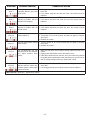
System Error Codes
Intelli-VentTM System Error Codes
OPERATION . . . . . . . . . . . . . . . . . . . . . . . . . . . . . 28
Performance Checks
28
Burner Manifold Pressure
Checking Input
Checking burner flame
SERVICE AND MAINTENANCE. . . . . . . . . . . . . . 28
Not Enough or No Hot Water
Energy Cut-off Control (ECO)
Water is Too Hot
Hot Water Odour
Discoloured Water
Water Heater Makes Noise
Extended Non Use Service
Condensation
Anode Maintenance
To inspect or change an anode:
Tank Flushing
Relief Valve Check
Vent Maintenance
Burner Maintenance
COMBO HEATING . . . . . . . . . . . . . . . . . . . . . . . . 31
System Requirements
31
Installation
32
Fan Coil
Baseboard Radiator Heating
Maintenance
32
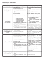
TROUBLESHOOTING GUIDE . . . . . . . . . . . . . . . 33
33
SUPERFLUETM
White-Rodgers Intelli-VentTM
35
INSTALLATION RECORD . . . . . . . . . . . . . . . . . . 36
LIMITED WARRANTY. . . . . . . . . . . . . . . . . . . . . . 37
RETAIN THESE INSTRUCTIONS IN A SAFE LOCATION FOR FUTURE REFERENCE
–3–
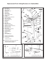
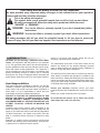
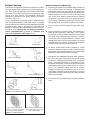
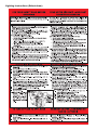
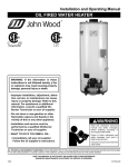
Replacement Parts Listing/Clearance to Combustibles
1.
2.
3.
4.
5.
6.
7.
8.
9.
10.
11.
12.
13.
14.
15.
16.
17.
18.
19.
20.
21.
22.
23.
24.
25.
26.
27.
28.
29.
30.
31.
32.
33.
34.
35.
36.
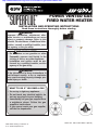
TERMINATION ELBOW WITH RODENT SCREEN
PIPE LENGTH *
PIPE COUPLING *
PIPE ELBOW *
RUBBER COUPLING
AIR TUBING
AIR SWITCH
JUNCTION BOX
JUNCTION BOX COVER
POWER CORD
BLOWER
BLOWER SUPPORT BRACKET
DRAFT DIVERTER
HIGH LIMIT SWITCH
ANODE (UNDER CAP)
INLET NIPPLE
DIPTUBE
T&P VALVE
DRIPTUBE *
BAFFLE ASSEMBLY
CONTROL VALVE (WHC)
CONTROL VALVE COVER (WHC)
INNER GAS DOOR
OUTER GAS DOOR
DRAIN VALVE
FLARE TUBE (GAS SUPPLY)
IGNITER ASSEMBLY
FLAME SENSOR
IGNITER BRACKET
ORIFICE
AIR SHUTTER
CAST IRON BURNER
2
4
M
IMU NCE
MIN ARA 2 in.)
E 1
CL mm (
0
0
3
36
1
5
7
6
8
13
15
9
10
14
16
11
17
12
18
34
19
20
UM
MINIM NCE
A
CLEAR in.)
(1
25mm
35
MIN
CLEIMUM
25mARAN
m ( CE
1 in
.)
21 22
MAX. PAN DEPTH
45mm (1 3/4 in.)
HEATING SYSTEM SUPPLY
HEATING SYSTEM RETURN
PVC ADAPTER
M
IMU NCE
MIN ARA n.)
i
E
CL m (2
m
0
5
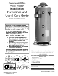
* OWNER SUPPLIED
Note: Manifold Tube Connections at Control Valve;
Right-Hand Threads for Natural Gas,
Left-Hand Threads for Propane
26
3
23 24
27
32
DRAIN PAN IF REQUIRED
MIN. DIA. 660mm (26 in.)
28
25
27
FLOOR DRAIN
31
26
28
29
32
29
31
30
30
CAST IRON BURNER ASSEMBLY USED
WITH THE INTELLI-VENTTM GAS VALVE.
CAST IRON BURNER ASSEMBLY USED
WITH THE 2000N WDER GAS VALVE.
Figure 1 Water Heater and Burner Assemblies
–4–
Your safety and the safety of others is very important.
We have provided many important safety messages in this manual and on your appliance.
Always read and obey all safety messages.
This is the safety alert symbol.
This symbol alerts you to potential hazards that can kill or hurt you and others.
All safety messages will follow the safety alert symbol and either the word
“DANGER” or “WARNING”.
DANGER You can be killed or seriously injured if you don’t immediately follow
instructions.
WARNING You can be killed or seriously injured if you don’t follow instructions.
All safety messages will tell you what the potential hazard is, tell you how to reduce the
chance of injury, and tell you what can happen if the instructions are not followed.
I) INTRODUCTION
We thank you for choosing a GSW/John Wood Water
Heater. Your satisfaction with this product is very important
to us. This gas-fired water heater has been developed to
produce potable hot water and may also be used in combination with space heating applications. The “Superflue”™
series is designed to vent the products of combustion (flue
gases) horizontally through an exterior wall or vertically
through the roof using an integrated blower assembly and
plastic piping, without the need for a conventional chimney.
User Responsibilities
This manual has been prepared to acquaint you with the
installation, operation and maintenance of your gas fired
water heater and provide important safety information in
these areas. It is your responsibility to ensure that your
water heater is properly installed and cared for.
FAILURE TO FOLLOW THE INSTRUCTIONS IN THIS
MANUAL MAY RESULT IN SERIOUS BODILY INJURY
AND/OR PROPERTY DAMAGE. THOROUGHLY READ
AND UNDERSTAND ALL INSTRUCTIONS BEFORE YOU
ATTEMPT TO INSTALL, OPERATE OR MAINTAIN THIS
HEATER.
Installation and service requires trade knowledge in the
areas of plumbing, electricity, venting, air supply and gas
supply. If you lack these skills or have difficulty understanding these instructions, you should not proceed. Enlist the
help of a qualified service technician to install this water
heater.
Examples of qualified service technicians include those
trained in the plumbing and heating industry, local gas utility personnel or an authorized service person.
Service to the Power Vent System should only be performed by a qualified service technician.
The manufacturer and seller of this water heater will not
assume any liability for any property damage, personal
injury or death resulting from improper sizing, installation or
failure to comply with these instructions.
The warranty on this water heater is in effect only when the
water heater is installed and operated in accordance with
these instructions. A data plate identifying your water heater
can be found above the gas control/thermostat. When referring to your water heater, always have the information listed
on the data plate readily available.
Protect your warranty: Regularly service your water
heater as directed in the "Maintenance" section of this manual.
Retain your original receipt as proof of purchase.
Do not discard this manual. You or future users of this
water heater will need it for reference.
–5–
II) SAFETY
This water heater is design-certified by CSA International as
a Category III, non-direct vented water heater that takes its
combustion air either from the installation area or from air
ducted to the unit from the outside.
In addition to the installation instructions found in this manual, the water heater must be installed in accordance with
all local and provincial or state codes or, in the absence of
such, with the latest editions of the following specifications.
For Installations in Canada:
"Natural Gas and Propane Installation Code" CAN/CSAB149.1 and "Canadian Electrical Code” (CAN/CSA
C22.1), Part I available from:
lar products, should not be stored or used near the water
heater or air intake. Due to the nature of air movement,
flammable vapours can be carried some distance from the
point of storage. The gas-fired water heater igniter or burner flame can ignite these vapours causing a flashback, fire
or explosion, which may result in severe property damage,
serious personal injury or death. If flammable liquids or
vapours have spilled or leaked in the area of the water
heater, leave the area immediately and call the fire department from a neighbor's home. Do not attempt to clean the
spill until all ignition sources have been extinguished.
Safety Warning (Scalding)
DANGER
Canadian Standards Association,
5060 Spectrum Way,
Mississauga, Ontario, Canada
L4W 5N6
For Installations in the United States:
"National Fuel Gas Code" ANSI Z223.1 (NFPA 54) and
"National Electrical Code" (NFPA 70) available from:
American National Standards Institute,
25 West 43rd Street,
New York, NY 10036
Massachusetts code requires this water heater to be
installed in accordance with Massachusetts Plumbing and
Fuel Gas Code 248 CMR Section 2.00 and 5.00.
Check your phone listings for the local authorities having
jurisdiction over your installation.
Safety Warning (Flammable Vapours)
Hot water produced by this appliance can cause severe
burns due to scalding. The hazard is increased for young
children, the aged or the disabled when water temperatures
exceed 52°C (125°F). Use tempering valves, also known as
mixing valves, in the hot-water system to reduce the risk of
scalding at point-of-use such as lavatories, sinks and
bathing facilities (see Figure 16). Such precautions must be
followed when this heater is operated in combination with
dishwashing or space heating applications.
Safety Warning (Carbon Monoxide)
W ARNI NG
DANGER
FLAMMABLES
Carbon Monoxide Warning
• Follow all vent system requirements by
the local authorities having jurisdiction
over your installation.
• Failure to do so can result in death, explosion or carbon monoxide poisoning.
Flammable Vapours
FIRE AND EXPLOSION HAZARD
Can result in serious injury or death
Do not store or use gasoline or other flammable vapours and liquids
in the vicinity of this or any other appliance. Storage of or use of gasoline
or other flammable vapours or liquids in the vicinity of this or any other
appliance can result in serious injury or death.
There is a risk of property damage, personal injury or death
from the by-products of combustion (e.g., flue gases), in
using fuel-burning appliances such as water heaters. Areas
that may not be suitable for water heater installation include
those where flammable liquids, gasoline, solvents, adhesives etc. are stored, or where engine-driven equipment or
vehicles are stored, operated or repaired. These, and simi-
As with all fuel burning equipment, this heater requires an
adequate supply of air for combustion and ventilation. An
insufficient air supply can result in poor combustion or the
re-circulation of the flue gases. Such a condition can cause
soot build-up and present a fire hazard. Flow reversal of flue
gases can cause an increase of carbon monoxide inside of
the dwelling that could result in serious bodily harm or death
from asphyxiation.
MAKE SURE THE FLOW OF COMBUSTION AND
VENTILATION AIR IS NOT RESTRICTED.
–6–
Relief Valve Requirements (T&P)
All water heaters must be fitted with a proper temperature
and pressure relief valve. These valves must be certified as
meeting the requirements of the "Standard For Relief
Valves For Hot Water Supply Systems”, ANSI
Z21.22/CSA 4.4.
If this water heater has been exposed to flooding, freezing,
fire or any unusual condition, do not put it into operation until
it has been inspected and approved by a qualified service
technician. THESE CONDITIONS CAN RESULT IN
UNSEEN INTERNAL DAMAGE and are not subject to warranty coverage.
CAUTION
Hydrogen gas can be produced in a hot water system
served by this heater that has not been used for a long
period of time (generally two (2) weeks or more).
Hydrogen gas is extremely flammable and can ignite
when exposed to a spark or flame. To reduce the risk of
injury under these conditions, it is recommended that the
hot water faucet be opened for several minutes at the
kitchen sink before using any electrical appliance connected to the hot water system. Use caution in opening
faucets. If hydrogen is present, there will probably be an
unusual sound such as air escaping through the pipe as
the water begins to flow. There should be no smoking or
open flame near the faucet at the time it is open.
III) INSTALLATION
Unpacking the Water Heater
WARNING
Excessive Weight Hazard
Use two or more people to move and install
water heater. Failure to do so can result in
back or other injury.
Important: Do not remove any permanent instructions,
labels, or the data label from outside of the water heater or
on the inside of panels.
•
Remove exterior packaging and place installation components aside.
• Inspect all parts for damage prior to installation and
start-up.
• Completely read all instructions before attempting to
assemble and install this product.
If you observe damage to the water heater or any of its components, DO NOT ASSEMBLE OR INSTALL IT OR MAKE
ANY ATTEMPT TO FIX THE DAMAGED PART(S). Contact
the place of purchase for further instructions.
• After installation, dispose of packaging material in the
proper manner.
IMPORTANT:
This water heater must be installed strictly in accordance
with the instructions enclosed, and local electrical, fuel
and building codes. It is possible that connections to the
water heater, or the water heater itself, may develop
leaks. IT IS THEREFORE IMPERATIVE that the water
heater be installed so that any leakage of the tank or related water piping is directed to an adequate drain in such a
manner that it cannot damage the building, furniture, floor
covering, adjacent areas, lower floors of the structure or
other property subject to water damage. This is particularly important if the water heater is installed in a multi-story
building, on finished flooring or carpeted surfaces. GSW
WILL NOT ASSUME ANY LIABILITY for damage caused
by water leaking from the water heater, pressure relief
valve, or related fittings. Select a location as centralized
within the piping system as possible. In any location
selected, it is recommended that a suitable drain pan be
installed under the water heater. This pan must limit the
water level to a MAXIMUM depth of 45mm (1 3/4 in.) and
have a diameter that is a minimum of 50mm (2 in.) greater
than the diameter of the water heater. Suitable piping shall
connect the drain pan to a properly operating floor drain.
When used with a fuel-fired heater, this drain pan must not
restrict combustion air flow.
Location Requirements
The water heater must be installed indoors in an area not
subject to freezing temperatures and in a vertical position
on a level surface. Water heaters located in unconditioned
spaces (e.g., attics, basements etc.) may require insulation
of the water piping, drain piping and venting to protect
against condensation. The power vented series of water
heaters are designed to vent the products of combustion
horizontally through the wall or vertically through the roof.
The blower expels the products of combustion by means of
plastic piping to the outdoors without the need for a conventional chimney.
Select a location as centralized within the piping system as
possible. The heater should be located in an area where
leakage of the tank or connections will not result in damage
to the area adjacent to the water heater or to lower floors of
the structure (see "IMPORTANT" notice above). Before
installing this water heater, consideration and planning must
be given to the following details:
• Proximity to walls and other objects (see "Clearance
and Accessibility").
• Air supply (see “Air Requirements”).
• Access to gas supply (see "Gas Supply").
• Routing and support of the vent piping and termination
(see "Exhaust Venting").
• Position of water supply and placement of water piping
and floor drain (see "Water Supply").
In Earthquake Zones
Note: The water heater must be braced, anchored, or
strapped to avoid moving during an earthquake. Contact
local utilities for code requirements in your area.
–7–
Note: The water heater may be installed in a closet with a
door off a bedroom or bathroom providing the units are
installed and vented per the manufacturer's instructions.
Important: If installing over carpeting, the carpeting must
be protected by a metal or wood panel beneath the water
heater. The protective panel must extend beyond the full
width and depth of the water heater by at least 76mm (3 in.)
in each direction or if in an alcove or closet installation, the
entire floor must be covered by the panel.
•
The water heater is certified for installation on a combustible floor.
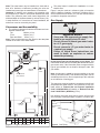
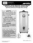
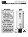
Figure 2 may be used as a reference guide to locate the
specific clearance locations. A minimum of 600mm (24 in.)
of front clearance and 100mm (4 in.) on each side should be
provided for inspection and service.
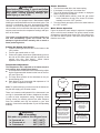
Gas Supply
DANGER
Clearances and Accessibility
•
The minimum clearances between the heater and combustible materials are:
Top
300mm (12 in.)
Front
100mm (4 in.)
Rear and Sides
25mm (1 in.)
Note: These requirements are also listed on the data plate
located on the front of the water heater.
•
•
•
•
“G”
•
HOT OUTLET
3/4” NPT
COLD INLET
3/4” NPT
Read the data plate to be sure the water heater is made
for the type of gas you will be using in your home. This
information will be found on the data plate located above the
gas control valve. If the information does not agree with the
type of gas available, do not install or attempt to start. Call
your dealer.
“H”
HEATING
OUTLET
T&P
VALVE
Note: An odourant is added by the gas supplier to the gas
used by this water heater. This odourant may fade over an
extended period of time. Do not depend upon this odourant
as an indication of leaking gas.
POWER CORD
(120) VAC/60Hz
“A”
“F”
Explosion Hazard
Use a new CSA approved gas supply line.
Install a gas supply shut-off valve.
Do not connect a natural gas water heater
to a L.P. gas supply.
Do not connect a L.P. gas water heater to
a natural gas supply
Failure to follow these instructions can
result in death, an explosion or carbon
monoxide poisoning.
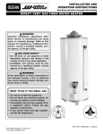
This gas piping must be installed in accordance with all local
and provincial or state codes or, in the absence of such, the
latest edition of "Natural Gas and Propane Installation
Code" CAN/CSA-B149.1 (Canada), or "National Fuel Gas
Code" ANSI Z223.1 (NFPA 54) (U.S.A.).
“E”
“D”
HEATING
INLET
Use properly sized gas piping and to ensure full gas input
and a properly sized gas supply regulator to ensure adeDRAIN
VALVE
GAS INLET
1/2” NPT
GAS
VALVE
MANUAL
GAS
SHUT-OFF
“I”
GROUND-JOINT
UNION
“C”
“B”
GAS
MANIFOLD
MODEL NO. A
B
C
D
E
F
G H
I
mm 610 302 432 1388 1575 1826 76 305 537
G/JW75
in. 24 11-7/8 17 54-5/8 62 71-7/8 3 12 21-1/8
Figure 2 Rough-in Dimensions
Figure 3 Gas Piping
–8–
76mm (3 in.)
SEDIMENT
TRAP
quate gas supply pressure. The supply piping and regulator
must be large enough to satisfy the requirements of all
appliances connected to the gas service and when all appliances are operating simultaneously. Undersize piping and
insufficient pressure can restrict the gas flow causing the
water heater to perform poorly. Improperly sized piping may
pose a safety hazard.
Note: When installing gas piping, apply sealing compounds
approved for use with natural and propane gas.
1. Install a readily accessible manual shut-off valve in the
gas supply line as recommended by the local utility. The
owner/operator must be shown the location of this valve
and be given instructions on how to use it to shut off the
gas to the heater.
2. Install a drip leg (if not already incorporated as part of
the water heater) as shown. The drip leg must be no
less than 76mm (3 in.) long for the accumulation of dirt,
foreign material, and water droplets.
3. Install a ground joint union between the gas control
/thermostat and the manual shut-off valve. This is to
allow easy removal of the gas control/thermostat.
4. Turn the gas supply on and check for leaks. Use a chloride-free soap and water solution (bubbles forming indicate a leak) or other approved method.
Gas Supply Pressure
WARNING
Exposure to a higher gas supply pressure
may cause damage to the control, resulting
in explosion or fire. Consult your local gas
supplier and gas authorities. DO NOT PUT
INTO SERVICE IF OVER-PRESSURIZATION
HAS OCCURRED.
Important: The gas supply pressure must not exceed the
maximum supply pressure as stated on the water heater's
data plate.
Gas line purging
Air may be present in the gas lines and could prevent the
burner from lighting on initial start-up. The gas lines should
be purged of air by a qualified service technician after installation of the gas piping system.
Gas Leak Testing
Important: This water heater and its gas connection must
be leak tested before placing the appliance in operation.
• If the code requires the gas lines to be tested at a pressure exceeding 14 in. w.c. (3.5 kPa), the water heater
and its manual shut-off valve must be disconnected
from the gas supply piping system and the line capped.
• If the gas lines are to be tested at a pressure less than
14 in. w.c. (3.5 kPa), the water heater must be isolated
from the gas supply piping system by closing its manual shut-off valve.
Gas Operating Pressures
The gas supply pressure and burner manifold pressure is
listed on the data plate located on the front of the heater
above the gas control/thermostat. Ensure the gas supply
pressure to the water heater and the burner manifold pressure are properly adjusted while all appliances are in operation. Refer to Figure 20 for Gas Control/Thermostat
Details.
U.L. and CSA recognized fuel gas and Carbon Monoxide
(CO) detectors are recommended in all applications and
should be installed using the manufacturer's instructions
and local codes, rules or regulations.
Air Requirements
WARNING
Failure to properly install this heater may
result in a fire hazard.
General
• An adequate air supply shall be provided for combustion and ventilation of this water heater. An insufficient
supply can result in poor combustion and possible sooting of the burner, combustion chamber or flue passageway. This may present a potential fire hazard or could
create a serious health hazard by producing carbon
monoxide.
Where an exhaust fan or any other air consuming appliance
(e.g., clothes dryer, furnace, etc.) is installed in the same
space as the water heater, sufficient air openings must be
available to provide fresh air when all appliances are operating simultaneously.
For buildings that are not well-sealed (do not have tight fitting doors and windows) natural air infiltration may provide
sufficient air required for combustion and ventilation. For
buildings using tight construction (newer and renovated
structures), the air supply shall be introduced from the outdoors, regardless of whether the space is confined or
unconfined.
Combustion Air “Supply” Ducts
Air supply ducts shall be of galvanized steel or equivalent
corrosion resistant material. A single air duct may not be
substituted when required for upper and lower air openings.
Horizontal combustion air ducts shall not slope downward
toward the air inlet.
Louvers and Grilles
Openings for air supply ducts must provide free unobstructed air movement. Louver and grille openings must be sized
to ensure that the FREE OPEN AREA is never less than the
area of the air duct.
–9–
Air Requirements
Important: Air for combustion and ventilation must not
come from a corrosive atmosphere. Any failure due to corrosive elements in the atmosphere is excluded from warranty coverage.
Installations in or for certain places including, but not limited
to, those listed below will require outdoor air for combustion
to reduce the risk of chemical exposure:
Beauty shops
Photo processing labs
Buildings with indoor pools
Water heaters installed in laundry, hobby or craft rooms
Water heaters installed near chemical storage areas
In such circumstances, outdoor combustion air may reduce,
but will not eliminate the presence of corrosive chemicals in
the air. Combustion air must be free of acid-forming chemicals such as sulfur, fluorine and chlorine. These elements
are found in aerosol sprays, detergents, bleaches, cleaning
solvents, air fresheners, paint and varnish removers, refrigerants and many other commercial and household products. When burned, vapours from these products form highly corrosive acid compounds. These products should not be
stored or used near the water heater or air inlet.
The area in which the heater is located is classified as either
"an unconfined space" or "a confined space."
An unconfined space is defined as a space having a volume not less than 50 cubic feet per 1000 BTU/hour (4.8
cubic metres per kilowatt) of combined input rating of all
appliances using the space. Adjacent open rooms may be
included as part of the unconfined space, provided there
are no closeable doors between these rooms. An example of this is an open basement.
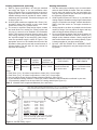
b). When using a single air supply, the duct shall terminate
within 300mm (12 in.) above and within 600mm (24 in.)
horizontally of the burner level of the appliance having
the largest input. For example: GSW's water heaters'
burners are 150mm (6 in.) from the floor, plus 300mm
(12 in.) equals 450mm (18 in.) as shown in Figure 4 (b).
All exterior vent openings are to be at least 300mm (12
in.) above the ground and clear of snow levels.
(a)
PERMANENT
OPENINGS
CONFINED
SPACE
UNCONFINED
SPACE
EQUIPMENT LOCATED IN CONFINED SPACES;
ALL AIR FROM INSIDE THE BUILDING.
(b)
300mm
(12 in.)
(MIN)
CONFINED
SPACE
GRADE
COMBINATION
COMBUSTION/
VENTILATION
AIR DUCT
600mm (24 in.)
A confined space is one smaller than described above.
For buildings using tight construction (newer and renovated
structures), the air supply shall be introduced from the outdoors, regardless of whether the space is confined or
unconfined.
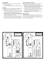
Confined Space Air Requirements for
Canadian Installations
Refer to Figure 4 (a), or (b), and Table 1 for proper sizing
and location of combustion air ducts and openings. CHECK
LOCAL CODES.
a). Two permanent openings shall be provided connecting
the confined space (e.g., closet, small room) with the
unconfined space. Each opening shall have a free area
of one square inch per 1,000 BTU/hour input (22
cm²/kW) of all appliances in the confined space. The top
opening shall be located as close to the ceiling as practical but never lower than the top of the heater. (see
Figure 4 (a)). The bottom opening shall be located neither more than 450mm (18 in.), nor less than 150mm (6
in.), above floor level.
Note: Ensure sufficient ventilation air to prevent elevated
temperatures in closets and confined spaces.
450mm (18 in.)
BASEMENT INSTALLATION, EQUIPMENT LOCATED
IN CONFINED SPACES; ALL AIR FROM OUTDOORS
Figure 4 Combustion Air Supply Openings And Ducts
(Canada)
Combined Input of
Required
All Appliances in
Free Area
Confined Space*
Acceptable Round
Duct Size Diameter
A**
B***
BTU / h
(kW / hr) cm2 in. 2 mm
in.
mm
in.
75,000
23
70
11
100
4
125
5
100,000
30
90
14
100
4
125
5
125,000
37
120
18
125
5
150
6
150,000
45
140
22
125
5
150
6
* All appliances refers to, and includes, those appliances
using the same air source (e.g. water heater, furnace,
boiler, clothes dryer etc.).
** Maximum allowable length of ductwork listed in column
A is 6.1 equivalent metres (20 ft.).
*** Maximum allowable length of ductwork listed in column
B is 15.2 equivalent metres (50 ft.).
Table 1 Air Supply Sizing (Canada)
– 10 –
Confined Space Air Requirements for
U.S. Installations
(a)
PERMANENT
OPENINGS
CONFINED
SPACE
UNCONFINED
SPACE
EQUIPMENT LOCATED IN CONFINED SPACES;
ALL AIR FROM INSIDE THE BUILDING.
(b)
COMBUSTION
AIR DUCT
PERMANENT
300mm VENTILATION
(12 in.)
AIR.
300mm
(12 in.)
ABOVE
GRADE
OR
SNOW
LINE
GRADE
CONFINED
SPACE
BASEMENT INSTALLATION, EQUIPMENT LOCATED
IN CONFINED SPACES; ALL AIR FROM OUTDOORS
(c)
300mm
(12 in.)
OUTDOORS
AIR DUCT
300mm (12 in.)
VENTILATION
COMBUSTION
CONFINED
SPACE
EQUIPMENT LOCATED IN CONFINED
SPACES; ALL AIR FROM OUTDOORS.
(d)
300mm (12 in.)
ATTIC LOUVERS TO OUTDOORS
OUTLET
AIR
Refer to Figure 5 (a), (b), (c) or (d) for proper sizing and
location of combustion air ducts and openings. CHECK
LOCAL CODES.
(a) Equipment located in confined spaces; all air from
inside the building.
Two permanent openings shall be provided connecting
the confined space (e.g., closet, small room) with the
unconfined space. Each opening shall have a free area
of one square inch per 1,000 BTU/hour input (22
cm²/kW) of all appliances in the confined space, but not
less than 100 square inches (645 cm²). The top opening shall commence within 300mm (12 in.) of the top of
space and the bottom opening shall commence within
300mm (12 in.) of the bottom of the enclosure.
(b) Basement installation, equipment located in confined spaces; all air from outdoors.
When supplying air directly from the outdoors, each
opening shall have a minimum free area of one square
inch per 4,000 BTU/hour input (5.5 cm²/kW) of total
input rating of all appliances in the confined space. The
inlets shall be a minimum of 300mm (12 in.) above the
grade (snow) line. The top opening shall commence
within 300mm (12 in.) of the top of the confined space.
(c) Equipment located in confined spaces; all air from
outdoors.
When supplying air directly from the outdoors using horizontal ducting, each opening shall have a free minimum area of one square inch per 2,000 BTU/hour (11
cm²/kW) of total input rating of all appliances in the confined space.
(d) Equipment located in confined spaces; all air from
outdoors through ventilated attic.
When supplying air directly through vertical ducting,
each opening shall have a free minimum area of one
square inch per 4,000 BTU/hour (5.5 cm²/kW) of total
input rating of all appliances in the confined space.
Note: Ensure sufficient ventilation air to prevent elevated
temperatures in closets and confined spaces.
INLET AIR
DUCT
CONFINED
SPACE
300mm (12 in.)
EQUIPMENT LOCATED IN CONFINED SPACES; ALL AIR
FROM OUTDOORS THROUGH VENTILATED ATTIC.
Figure 5 Combustion Air Supply Openings And Ducts
(U.S.A.)
– 11 –
Burn Hazard
Do not touch vent.
Doing so can result in
burns.
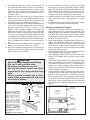
Exhaust Venting
This heater is designed to exhaust the products of combustion (flue gases) to the outdoors using a sealed piping system. Table 2 lists the allowable vent materials and sizing
information. Figure 8 shows the general venting layout while
Figures 9-12 show various end termination details and
clearances. Connection of the venting piping to the blower
is shown in Figure 14.
Correct installation of the venting system is essential to the
safe and efficient operation of this water heater. Vent piping
must be installed in accordance with all applicable local and
provincial or state codes. In the absence of such codes, all
installation shall meet the requirements as stated in the latest edition of the "Natural Gas and Propane Installation
Codes" CAN/CSA-B149.1 (Canada) or "National Fuel
Gas Code" ANSI Z223.1 (NFPA 54) (U.S.A.).
STREET ELBOW
Important Notes and Warnings
• This heater is certified to be installed using Schedule 40
PVC or CPVC plastic vent material. In Canada some
jurisdictions require that this material be approved to
ULC S636. ULC S636 mandates that components from
different systems must not be mixed in the same vent
runs. Check local codes to determine which materials
are allowed in your area and only use approved material. All venting material and components must be joined
with the approved primer/cleaner and solvent cement.
•
Do not common vent this heater with any other appliance.
•
During operation the plastic piping will expand as it
heats up and contract as it cools down. This is normal
for this type of venting. Rigidly fastening the vent piping
can cause undue stress that may result in the cracking
or fracturing the vent piping material. A fracture of the
venting pipe poses a serious safety hazard. To prevent
stressing of the vent system, all hangers and supports
must allow the vent piping freedom to move.
•
All power vented water heaters generate a certain
amount of operational noise. In order to minimize noise
transmission to the support structure, use isolation pads
between the pipe hangers and the vent pipe.
•
Most power vent installations develop some condensation in the vent piping. When using long runs of venting
or when the venting passes through cold or unheated
areas, considerable amounts of condensate from the
flue gases can develop. Provision must be made for the
condensate to drain freely from the system or to be collected in a condensate trap(s) that can be drained.
Damage or fracture of the vent piping may occur if the
condensate is allowed to collect and freeze. Pooling of
condensate can restrict airflow and can cause nuisance
failures of the system.
•
Be aware of any concealed wiring or piping inside the
walls.
NORMAL ELBOW
150mm
(6 in.) min.
BACK TO BACK ELBOWS
PREFERRED PRACTICE
90° SHORT SWEEP ELBOW
90° LONG SWEEP ELBOW
Figure 6 Correct Pipe Fittings
VENT LENGTH LESS THAN OR
EQUAL TO 6.1 EQUIVALENT METRES
(20 FT.) USE PLASTIC SCREEN.
VENT LENGTH GREATER THAN 6.1
EQUIVALENT METRES (20 FT.) USE
STEEL MESH SCREEN.
Figure 7 Rodent Screens
– 12 –
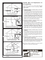
Venting terminations and sizing
• Refer to Figure 8 and Table 2 for vent pipe materials
and sizing and Figure 11 for vent termination clearances. Examples of the vent terminations are shown in
Figures 9 and 10. If the installation requires a vent riser,
suitable drainage must be provided to ensure condensation does not accumulate. Termination through a roof
is shown Figure 12.
• G/JW75 gallon models are supplied with a 76mm (3 in.)
termination elbow that includes a steel mesh rodent
screen and a 76mm (3 in.) plastic screen.
• The screen is required to keep foreign objects, rodents
and small birds from entering the venting system and
only one (1) screen is to be installed in the termination
elbow. These screens have been sized to ensure maximum energy efficiency of the venting system based on
the "equivalent length" of the vent piping. How to determine the equivalent length is shown in Figure 8. The
appropriate screen is to be installed into the end of the
termination elbow and secured with a small amount of
silicone sealant. This will allow for easy removal for
inspection and cleaning.
WATER
VENT PIPE
HEATER SUFFIX
SIZE
MODEL
G/JW75
SNV,
SPV
Venting instructions
1. Plan the venting layout starting at the vent termination
and work back toward the heater. Take into consideration the style and position of the vent termination, the
vent pipe routing, elbows and connectors required and
the necessary support hangers.
2. G/JW75 gallon heaters use 76mm (3 in.) schedule 40
venting material. Allowable venting length is determined
using the “Equivalent vent length” method described in
Table 2. See also section on “Vent pipe connection to
blower”.
3. Venting should be as direct as possible with the fewest
number of fittings. Use long radius 45-degree and long
radius 90-degree elbows wherever possible.
4. Do not use 90-degree elbows "back to back" and do not
use street elbows. Maintain a minimum 150mm (6 in.)
straight section between elbows. Closely coupled and
short radius elbows reduce the venting capacity. Figure
6 shows examples of vent pipe connections.
5. DO NOT USE AN ELBOW AS A SUPPORT POINT.
Elbows are not designed to carry the weight of the venting system.
PRESSURE
SWITCH
SETTING
* VENT
MAXIMUM EQUIVALENT MINIMUM EQUIVALENT
MATERIAL
VENT LENGTH
VENT LENGTH
(SCHEDULE 40)
15.2m (50 ft.) +
0.91m (3 ft.) + one 90°
- 0.50 in. w.c.
76mm (3 in.)
PVC**, CPVC termination elbow with
elbow + termination elbow
(-.124 kPa)
steel mesh screen
with plastic screen
Notes:
1. Each 76mm (3 in.), 90° elbow is equivalent to 2.44m (8 ft.) of vent length.
2. Each 76mm (3 in.), 45° elbow is equivalent to 1.22m (4 ft.) of vent length.
3. Use long radius elbows. Minimum distance between elbows is 150mm (6 in.).
4. Do not mismatch venting materials. *Check local codes to determine which materials are allowed in your area.
5. **Pipe assembly adapter must be used with PVC venting material (see Figure 13).
Table 2 Allowable Vent Lengths and Materials (Vert. and Horiz.).
NOTE: VENT PIPE MUST BE SUPPORTED EVERY 1.2m (4 ft.). TO PREVENT VIBRATION, USE ISOLATION
PADS WHEN ATTACHING STRAPS TO FLOOR JOISTS, WALLS OR CEILINGS.
TERMINATION
ELBOW
RODENT SCREEN
(INSTALL INTO
ELBOW)
GROUND LEVEL OR
MAXIMUM SNOW
LINE*
45°
ELBOW
STRAP
Example for calculating equivalent feet.
Section “A” . . . . . . 0.15m . . (0.5 ft.)
90° elbow . . . . . . . 2.44m . . (8.0 ft.)
Section B . . . . . . . 0.31m . . (1.0 ft.)
45° elbow . . . . . . . 1.22m . . (4.0 ft.)
Section C . . . . . . . 0.46m . . (1.5 ft.)
45° elbow . . . . . . . 1.22m . . (4.0 ft.)
Section D . . . . . . . 4.57m . (15.0 ft.)
Total Equivalent . 10.37m . (34.0 ft.)
Based on this example use the (fully open) rodent
screen for vent length greater than 6.1 equivalent
metres (20 equivalent ft.) (see Figure 7).
Figure 8 General Venting Layout
– 13 –
90°
ELBOW
PVC ADAPTER
(SUPPLIED)
150mm
(6 in.)
MIN.
150mm (6 in.)
ATTACH 90°
TERMINATION
ELBOW
VENT PIPING MAY BE
SLOPED
IN
ANY
DIRECTION, AS LONG
AS A WATER TRAP IS
NOT CREATED IN
THE VENTING SYSTEM. THE SLOPE
SHOULD BE KEPT TO
A MINIMUM SO AS
NOT TO EXERT ANY
UNDUE STRESS ON
THE PIPE.
RODENT SCREEN
(INSTALL INTO
ELBOW)
300mm
(12 in.)
MIN.
GROUND LEVEL
OR MAXIMUM
SNOW LINE*
ATTACH 90°
TERMINATION
ELBOW
SEALANT
SEALANT
300mm
(12 in.)
MIN.
BRACKET
EQUIVALENT
VENT LENGTH
MEASURED FROM
THIS POSITION
RODENT
SCREEN
(INSTALL
INTO
ELBOW)
SEALANT
VENT
RISER
GROUND LEVEL
OR MAXIMUM
SNOW LINE*
VENT PIPING TO BE
SLOPED (DOWN)
TOWARD HEATER TO
PREVENT WATER
FROM COLLECTING.
SEALANT
* WHERE SNOW COVER IS NORMAL DURING WINTER, ENSURE
SUFFICIENT VENT CLEARANCE TO PREVENT BLOCKAGE OR ICE BUILDUP.
Figure 9 Vent Termination Exterior Installation
* WHERE SNOW COVER IS NORMAL DURING WINTER, ENSURE
SUFFICIENT VENT CLEARANCE TO PREVENT BLOCKAGE OR ICE BUILDUP.
Figure 10 Installation Of Fabricated Vent Riser.
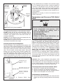
D
F
CL
F
F
F
F
A
G
B
E
AIR
MECHANICAL
T
LE
IN
LY
PP
SU
1. ("A") Minimum 2.1m (7 ft.) above a paved sidewalk or
paved driveway that is located on public property.
2. ("B") Minimum 900mm (3 ft.) above any forced air or
mechanical air supply inlet located within 1.8m (6 ft.)
horizontally (Canada) or 3m (10 ft.) (U.S.A.).
3. ("C") Within 900mm (3 ft.) of any gas service regulator
vent outlet.
4. ("D") Minimum 900mm (3ft) horizontally of the vertical
centerline above the regulator vent outlet to a maximum
vertical distance of 4.5m (15ft).
5. ("E") Minimum 305mm (1 ft.) above grade level or anticipated snow level.
C
D
GAS METER AN
REGULATOR
ada),
1.8m (6 ft.) (Can
.A.)
3m (10 ft.) (U.S
6. ("F") Within 305mm (1 ft.) of any window or door that
can be opened, of any non-mechanical air supply inlet
or of the combustion air inlet of any other appliance.
7. ("G") Minimum 305mm (1 ft.) distance between the top
of the vent termination and the underside of a veranda,
porch or deck.
8. The manufacturer recommends the vent termination
shall not be mounted directly above or within 900mm (3
ft.) horizontally from an oil tank or gas meter to avoid
potential freeze-up or fouling from condensation.
Figure 11 Horizontal Vent Terminal Installations
– 14 –
6. Calculate "Equivalent Vent Length" before starting. Do
not exceed the values shown in Table 2. An example of
how this length is determined is shown in Figure 8. The
value from your calculations should also be used to
determine which rodent screen to install into the vent
termination elbow.
7. Measure the vent piping and cut to required lengths.
Pipes must be cut at right angles and deburred to
ensure a good smooth fit with sufficient overlap for the
glue joints. Correct any interference conditions.
8. Provide support hangers for horizontal vent piping every
1.2m (4 ft.) to prevent sagging and stress. Provide a
minimum of 3mm (1/8 in.) rise per 1.2m (4 ft.) of vent
piping to ensure adequate drainage. Horizontal vent
piping must not sag to form valleys where condensate
may collect. Vertical venting shall be supported every
1.5m (5 ft.). Use appropriate support straps and vibration isolators (foam pads) on straight sections only. Do
not use elbows as support points. Allow sufficient clearance for expansion and contraction of the venting system.
9. At the point where the vent pipe exits the building, cut a
90mm (3-1/2 in.) hole for 76mm (3 in.) venting.
10. Insert the vent piping through this hole and secure into
position. Connect the vent pipe to the end termination
elbow as shown in Figures 9-12.
•
•
•
•
CAUTION:
Use of Solvent Cement and Primer
Use only in well-ventilated areas.
Do not use near flame or open fire.
Use only the Solvent Cement and Primer
appropriate for the venting material being
used.
Solvent cements for plastic pipe are flammable liquids and must be kept away from
all sources of ignition.
76mm (3 in.)
MIN. LENGTH
A VENT USED IN A SPECIAL
VENTING SYSTEM WITH
POSITIVE VENT PRESSURE
AND PASSING THROUGH A
ROOF SHALL EXTEND AT
LEAST 450mm (18 in.)
ABOVE
THE
HIGHEST
POINT WHERE IT PASSES
THROUGH THE ROOF SURFACE AND ANY OTHER
OBSTRUCTION WITHIN A
HORIZONTAL DISTANCE OF
450mm (18 in.). A VERTICAL
VENTING SYSTEM MUST
BE SUPPORTED EVERY
2.4m (8 ft.).
Figure 12 Vertical Venting
TERMINATION
MAY BE 90°
ELBOW OR A
“T” ELBOW
450mm
(18 in.)
RODENT
SCREEN
(INSTALL
INTO
ELBOW)
11. Dry fit all vent pipes, elbows, connectors and fittings
before joining any parts with solvent cement. PARTS
MUST FIT WITHOUT STRESS OR BENDING OF ANY
SECTION and each connection must overlap a minimum of 13mm (1/2 in.). Do not force fit any of the connections. Use only the appropriate solvent cement.
12. Install the properly sized rodent screen into the outlet
elbow and secure with a small quantity of silicone
sealant.
13. Do not seal the vent piping to the wall until the venting
is properly connected to the blower assembly.
Vent pipe connection to blower
1. The plastic vent piping connects into the rubber coupling located on the top of the blower assembly. This
coupling includes gear clamps to connect the venting to
the blower. These connections must be properly seated
and tightened to prevent the leakage of flue gases into
the area. See Figures 13 & 14.
2. G/JW75 gallon heaters are supplied with a 76mm (3 in.)
adapter for installations using PVC vent piping. This
adapter must be used when using PVC piping. Securely
attach the PVC adapter to the first section of PVC vent
piping using the proper solvent cement before installation into the blower coupling.
3. G/JW75 gallon heaters using CPVC vent piping may be
connected directly into the rubber coupling.
4. Clean and lightly sand the end of the CPVC plastic vent
piping or PVC adapter that will connect into the rubber
coupling.
5. Loosen the upper clamp on the rubber coupling and
insert the sanded end of the CPVC vent piping or the
PVC adapter a full 32mm (1-1/4 in.). Do not use glue or
sealant in the rubber coupling. Check that there is no
stress on the connection or the vent piping that may be
caused by twisting or bending.
6. Tighten the upper clamp so that the vent piping is firmly secured in the coupling and is gas tight. Do not over
tighten or cause distortion of any of the parts. Ensure
that the bottom of the rubber coupling is firmly seated
on the blower outlet and that the lower gear clamp is
also secure. Check to ensure that there is no distortion
or movement of the clamped assembly once it is completed.
PVC PIPE
COUPLING
76mm (3 in.)
ADAPTER
FOR PVC
PIPE
(CPVC)
UPPER GEAR
CLAMP
ROOF
LINE
RUBBER
ADAPTER
LOWER
GEAR CLAMP
Figure 13 Pipe Assembly Adapters
– 15 –
4. If installing the water heater in a closed water system,
install an expansion tank in the cold water line as specified under "Closed System/Thermal Expansion".
5. Install a shut-off valve in the cold-water inlet line. It
should be located close to the water heater and be easily accessible. The owner/operator must be shown the
location of this valve and be given instructions on how
to use it to shut off the water to the heater.
VENT PIPE
76mm (3 in.)
BLOWER ASS’Y WITH RUBBER COUPLING FOR 76mm
(3 in.) NOMINAL PVC VENT
PIPE.
150mm (6 in.)
MIN
ADAPTER
CPVC VENTING DOES NOT
REQUIRE ADAPTER.
RUBBER
COUPLING
Figure 14 Blower, Fittings and Vent Pipe Options
CAUTION:
• Do Not Overtighten The Top And Bottom
Gear Clamps Of The Rubber Coupling.
• Do Not Apply Solvent Cement Or Silicone
To The Rubber Coupling Connection.
7. Complete the venting installation by sealing around the
termination assembly where it passes through the outside wall, inside and out, with silicone or other suitable
sealant.
Water Supply
Piping Installation
Piping, fittings, and valves should be installed according to
the installation drawing (Figure 15). A pressure-reducing
valve and/or an expansion tank may be required for installations where the water pressure is high. The pressure-reducing valve should be located on the supply to the entire building in order to maintain equal hot and cold water pressure.
Important:
• Do not apply heat to the water fittings on the heater as
they may contain nonmetallic parts. If solder connections are used, solder the pipe to an adapter before
attaching the adapter to the hot and cold water fittings.
• Some models may contain energy saving heat traps to
prevent the circulation of hot water within the pipes. Do
not remove the inserts within the heat traps.
• Always use a proper grade of joint compound and be
certain that all fittings are drawn up tight.
1. Install the water piping and fittings as shown in Figure
15. Connect the cold water supply to the fitting (3/4"
NPT) marked "COLD" (or "C"). Connect the hot water
supply to the fitting (3/4" NPT) marked "HOT" (or "H").
2. The installation of unions in both the hot and cold water
supply lines is recommended.
3. The manufacturer of this water heater recommends
installing a tempering valve in the domestic hot-water
line as shown in Figure 16. These valves reduce the
point-of-use water temperature by mixing cold and hot
water. Contact a licensed plumber or the local plumbing
authority.
Filling the Water Heater
Do not insert the power cord into the electrical receptacle
until all the following steps have been completed.
1. Make sure the drain valve is closed.
2. Open all hot-water faucets served by the system to
allow air to escape from the tank.
3. Open the cold-water inlet valve.
Note: When filling, avoid water leakage. Do not allow the
insulation of the water heater to get wet as water can reduce
the effectiveness of the insulation.
4. When an uninterrupted stream of water, without apparent air bubbles, flows from the open hot-water faucets,
the tank is full.
5. Close the hot-water faucets and check the system for
leaks. Repair as required and retest.
Please note the following:
DO NOT install this water heater with iron piping. The system should be installed only with piping that is suitable for
potable (drinkable) water such as copper, CPVC, PEX or
polybutylene. DO NOT use PVC water piping.
DO NOT use any pumps, valves, or fittings that are not compatible with potable water.
DO NOT use valves that may cause excessive restriction to
water flow. Use full flow ball or gate valves only.
IN A CLOSED SYSTEM USE EITHER: 1.THERMAL EXPANSION TANK
OR
2.PRESSURE RELIEF VALVE.
HOT
WAT E R
OUTLET
UNION
NOTE: BLOWER
ASSEMBLY NOT
SHOWN
FOR
CLARITY.
COLD WATER
INLET VALVE
PRESSURE
REDUCING
VALVE
WITH
BYPASS
COLD WATER
INLET
TEMPERATURE
AND
PRESSURE RELIEF VALVE
DISCHARGE LINE 300mm
(12 in.) max (CANADA) OR
150mm (6 in.) max (U.S.)
ABOVE DRAIN
MASSACHUSETTS: INSTALL A
VACUUM RELIEF IN COLD WATER
LINE PER SECTION 19MGL 142
Figure 15 Water Piping Installation
– 16 –
DRAIN PAN CONNECT TO
PROPERLY OPERATING
FLOOR DRAIN.
FOLLOW THE
TEMPERING
VALVE MANUFACTURER'S
INSTRUCTIONS
LD
CO
TEMPERED
WATER TO
FIXTURE
TER
WA
T&P VALVE
AND DISCHARGE
LINE
HOT
WATER
OUTLET
TEMPERING
VALVE (SET
TO 49°C
(120°F))
able for potable water) be installed on the cold water supply
line. The expansion tank must have a minimum capacity of
5.6 litres (1.5 US gallons) for every 190 litres (50 US gallons) of stored water and be rated at the working pressure
of the water heater. Contact the local water supplier or
plumbing inspector for information on other methods to control this situation.
Important: Do not plug or remove the temperature and
pressure relief valve.
Temperature and Pressure (T&P) Relief
Valve
COLD
WATER
INLET
WARNING
Figure 16 Tempering Valve Installation
DO NOT use any lead based solder in potable water lines.
Use appropriate tin-antimony or other equivalent material.
DO NOT tamper with the gas control/thermostat, igniter or
temperature and pressure relief valve. Tampering voids all
warranties. Only qualified service technicians should service these components.
DO NOT use with piping that has been treated with chromates, boiler seal, or other chemicals.
DO NOT add any chemicals to the system piping which will
contaminate the potable water supply.
Closed System/Thermal Expansion
Periodic discharge of the temperature and pressure relief
valve may be due to thermal expansion in a closed water
supply system. The water utility supply meter may contain a
check valve, backflow preventer or water pressure-reducing
valve. This will create a closed water system. During the
heating cycle of the water heater, the water expands causing pressure inside the water heater to increase. This may
cause the temperature and pressure relief valve to discharge small quantities of hot water. To prevent this, it is
recommended that a diaphragm-type expansion tank (suit-
DRAIN PAN. CONNECT TO
PROPERLY OPERATING
FLOOR DRAIN.
Pressure
Relief
For protection against excessive pressures and temperatures, a temperature and pressure relief valve must be
installed in the opening marked "T&P RELIEF VALVE" (see
Figure 17). This valve must be design certified by a nationally recognized testing laboratory that maintains periodic
inspection of the production of listed equipment or materials
as meeting the requirements of the "Standard For Relief
Valves For Hot Water Supply Systems", ANSI
Z21.22/CSA 4.4. The function of the temperature and pressure relief valve is to discharge water in large quantities in
the event of excessive temperature or pressure developing
in the water heater. The valve's relief pressure must not
exceed the working pressure of the water heater as stated
on the data plate.
The Temperature and Pressure Relief Valve:
• Must not be in contact with any electrical part.
• Must be connected to an adequate discharge line.
• Must not be rated higher than the working pressure
shown on the data plate of the water heater.
DISCHARGE LINE 19mm (3/4 in.)
MIN. DO NOT CAP OR PLUG.
&
•
•
•
Important: Only a new temperature and pressure relief
valve should be used with your water heater. Do not use an
old or existing valve, as it may be damaged or not adequate
for the working pressure of the new water heater. Do not
place any valve between the relief valve and the tank.
TEMPERATURE AND
PRESSURE RELIEF
VALVE
Figure 17 Temperature
Installation
•
Explosion Hazard
If the temperature and pressure relief
valve is dripping or leaking, have a
licensed plumber repair it.
Do not plug valve.
Do not remove valve.
Failure to follow these instructions can
result in death or an explosion.
Valve
The Discharge Line/Driptube:
• Must not be smaller than the pipe size of the relief valve
or have any reducing coupling installed in the discharge
line.
– 17 –
•
•
•
•
Must not be capped, blocked, plugged or contain any
valve between the relief valve and the end of the discharge line.
Must terminate a maximum of 300mm (12 in.) (Canada)
or 150mm (6 in.) (U.S.A.) above the floor.
Must be capable of withstanding 121°C (250°F) without
distortion.
Must be installed to allow complete drainage of both the
valve and discharge line.
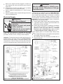
Electrical Supply
WARNING
Electrical Shock Hazard
• Disconnect power before
servicing.
• Replace all parts and panels
before operating.
• Failure to do so can result in
death or electrical shock.
A three-wire cord and plug is provided with this water
heater. The plug shall be connected into an electrically
grounded, 120 VAC, 60 Hz, 15 Amps, fused receptacle.
Important: The electrical controls used inside the gas control/thermostat of this water heater are polarity sensitive.
Ensure the electrical supply is connected correctly in the
receptacle box. Failure to connect correctly will prevent the
unit from functioning properly. Before performing any elec-
WARNING
When the unit is plugged in, 120VAC is present at the electric connections of the gas
control/thermostat.
trical service work, label all wires to avoid connection errors.
If wiring has to be replaced, use only TYPE TEW 105°C
wire, (except igniter wires). If there is a problem with igniter
wires, replace igniter assembly in its entirety. In locations
where a sump pump failure, flooding or exposure to water
may be present, a ground fault receptacle is recommended.
Important: Do not use an extension cord to connect the
water heater to an electrical outlet.
• Ensure that the water heater and the outlet are properly grounded. Failure to properly ground the heater can
prevent the unit from operating.
• Ensure that the water heater is installed in accordance
with prevailing provisions of local codes, or, in the
absence of such, the latest edition of "Canadian
Electrical Code” (CAN/CSA C22.1), Part I (Canada)
or "National Electrical Code" (NFPA 70) (U.S.A.).
Before applying power to the water heater, always make
sure:
• The voltage and frequency correspond to that specified
on the water heater wiring diagram.
• The electrical outlet has the proper overload fuse or
breaker protection.
HIGH LIMIT
SWITCH
PRESSURE
SWITCH
BEIGE
HOUSING
IGNITER
E5
E4
E3
E2
E1
EXTERNAL MONITOR LIGHT
Figure 18 Wiring Diagram - White-Rodgers Control
GAS
VALVE
FLAME
SENSOR
BLOWER
L1 N GND
Figure 19 Wiring Diagram - (WDER 2000N)
– 18 –
•
Fill the tank with water and check all connections for
leaks. Open the nearest hot-water faucet and let it run
for 3 minutes to purge the water lines of air and sediment and to ensure complete filling of the tank. The
electrical power may then be turned on. Verify proper
operation after servicing.
SUPPLY INLET GAS PRESSURE
Note: Always reference the wiring diagram for the correct
electrical connections.
BURNER MANIFOLD GAS PRESSURE
NATURAL GAS
7.0 in. w.c. (1.7kPa)
NATURAL GAS
3.5 in. w.c. (0.9kPa)
PROPANE GAS
11.0 in. w.c. (2.7kPa)
PROPANE GAS
10.0 in. w.c. (2.5kPa)
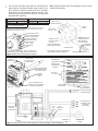
SUPPLY INLET
PRESSURE PORT
MAXIMUM SUPPLY INLET PRESSURE
14.0 in. w.c. (3.5kPa) ALL GASES
THIS GAS CONTROL IS EQUIPPED WITH AN ECO (ENERGY CUT-OFF)
THE ECO WILL SHUT THE GAS OFF SHOULD THE OUTLET WATER
TEMPERATURE EXCEED 93° (200°F)
SAFETY
COVER
SUPPLY GAS
INLET 1/2” NPT
GAS CONTROL SWITCH
GAS VALVE CONNECTOR
QUICK CONNECTORS
MAIN AND IGNITER
PRESSURE SWITCH
AND INDUCER
GAS VALVE
CONNECTOR
BURNER MANIFOLD
PRESSURE ADJUSTMENT (REMOVE
DIAL FOR ACCESS
MANIFOLD CONNECTION UNDER
CONTROL
INCREASE
PRESSURE
MANIFOLD PRESSURE
PORT UNDER CONTROL
GND
LED INDICATOR
GAS CONTROL/THERMOSTAT - VIEW OF ELECTRICAL
CONNECTIONS, WITH COVER REMOVED (WDER 2000N)
GAS CONTROL VIEWED FROM GAS INLET
WITH TEMPERATURE DIAL REMOVED
DECREASE PRESSURE
Figure 20 Gas Valve/Temperature Control
3/4” NPT. WRAP
WITH TEFLON TAPE
(2 WRAPS MIN.)
GROUND
CONNECTION
TEMPERATURE
INDICATORS
MANIFOLD PRESSURE
ADJUSTMENT (REMOVE
CAP FOR ACCESS)
OUTLET
PRESSURE
PORT
QUICK CONNECTS FOR
POWER SUPPLY AND IGNITER
LOCATED ON UNDERSIDE
GAS CONTROL
SIDE VIEW
TEMPERATURE
ADJUSTMENT
BUTTONS
GAS INLET
1/2” NPT
GAS CONTROL
FRONT VIEW
GAS OUTLET
TO BURNER
IGNITER AND FLAME
PROBE ASSEMBLY
BLACK
WHITE
HIGH
AIR
LIMIT
PRESSURE
SWITCH
SWITCH
INTELLI-VENTTM
CONTROL
BOTTOM VIEW
GREEN
CONNECTOR
Figure 21 Gas Control/Thermostat Details and Wiring Diagram (White-Rodgers)
– 19 –
GREEN
TO POWER SUPPLY
DISCONNECT AND
OVERLOAD
PROTECTION
COMBUSTION
BLOWER
Installation Checklist
1.
2.
3.
4.
5.
6.
7.
8.
9.
10.
11.
12.
13.
14.
15.
16.
Check Here
Have the safety precautions described in this
manual been implemented?
Does the gas piping conform to the recommendations of your Gas Utility Company?
Has the gas piping been tested?
Is the supply pressure correct?
Is the water heater connected to the correct
gas supply as shown on the rating plate
(Natural Gas/Propane)
Is the clearance between the water heater and
combustible construction as per specifications?
Is the water piping correctly connected? Are
you certain that there are no leaks?
Is the water heater filled with water?
Is the cold water supply valve open?
Is the vent pipe installed properly and are the
vertical and horizontal runs properly supported?
Is the vent hood air intake opening unobstructed?
Is the T&P valve installed? Is the drain pipe
from the T&P valve unobstructed?
Is a drain pan installed (if required) with a proper overflow pipe, directed to a drain?
Have you taken steps to prevent water damage
in case of leaks?
Is the electric supply a 120V, electrically
grounded, 15A fused, correct polarity circuit?
Does the area around the water heater have
adequate ventilation?
If the answer to all of the questions
above is “Yes”, read the Operating
Instructions and proceed with lighting
the heater.
– 20 –
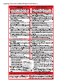
Mixing Valves
IV) OPERATING INSTRUCTIONS
CAUTION:
Read before proceeding. If you do not
follow these instructions exactly, a fire or
explosion may result, causing property
damage, personal injury or loss of life.
This appliance is equipped with an ignition
device that automatically lights the burner.
Do not try to light manually with
a match or flame.
Temperature Regulation
This water heater’s intended purpose is to heat water. Hot
water is needed for cleaning and sanitizing (bodies, dishes,
clothing etc.). Untempered hot water can present a scald
hazard. Depending on the time element and the people
involved (adults, children, elderly, infirm etc.) scalding may
occur at different temperatures.
It is recommended that lower temperatures be used to avoid
the risk of scalding. It is further recommended that the water
temperature be set for the lowest temperature that will satisfy your hot-water needs. This will also provide the most
energy efficient operation of the water heater.
Short, repeated heating cycles caused by small water uses
can cause temperatures at the point-of-use to exceed the
thermostat setting by up to 17°C (30°F). This condition is
referred to as “stacking”. If you experience this type of use
you should consider using lower temperature settings to
reduce scald hazards.
Valves for reducing the point-of-use temperature by mixing
cold and hot water are available.
Hot water can scald: Water heaters are intended to produce hot water. Water heated to a temperature that will satisfy space heating, clothes washing, dish washing, and
other sanitizing needs can scald and permanently injure you
upon contact. Some people are more likely to be permanently injured by hot water than others. These include the
elderly, children, the infirm, and physically/mentally handicapped.
If any one using the hot water fits into one of these groups
or if there is a provincial, state or local code requiring a certain temperature water at the hot water faucet, then you
must take special precautions. In addition to using the lowest possible temperature setting that will satisfy your hotwater needs, a means such as a mixing valve, should be
used at the hot-water faucets or at the water heater. Mixing
valves are available at plumbing supply or hardware stores.
Follow manufacturer’s instructions for installation of these
valves. Before changing the factory settings on the thermostat, read the “Temperature Regulation” section in this manual.
WARNING
Never allow small children to use a hot-water
faucet, or to draw their own bath water.
Never leave a child or impaired person unattended in a bathtub or shower. Scald burns
can result.
WARNING
DANGER
Scald burns occur in under one second with
71°C (160°F) water, which the thermostat will
deliver if the temperature is set at “VERY
HOT”. Lower settings of the temperature will
reduce the risk of scald and will reduce your
fuel bill.
Water temperature over 52°C (125°F) can cause
severe burns instantly or death from scalds.
Children, disabled and elderly are at highest risk of
being scalded.
Feel water before bathing or showering.
Temperature limiting valves are available.
– 21 –
WARNING
Risk of scalding
Hot water can produce third degree burns
in 6 seconds at . . . . . . . .60°C (140°F)
in 30 seconds at . . . . . . .54°C (130°F)
in 5 minutes at . . . . . . . . .49°C (120°F)
Lighting Instructions (Robertshaw)
– 22 –
CAUTION:
Read before proceeding. If you do not follow
these instructions exactly, a fire or explosion
may result, causing property damage, personal injury or loss of life.
Gas Control/Thermostat
This heater may be equipped with a Robertshaw WDER
2000N gas control/thermostat and a hot-surface igniter. This
control is a combination gas valve, thermostat and ignition
controller for use on this power vented water heater. The
valve contains a micro-controller that supervises the ignition
sequence and monitors the temperature settings and operation of the heater.
This heater is equipped with a hot-surface ignition system that automatically ignites the burner. Do not
attempt to light this heater manually with a match or
flame-producing device.
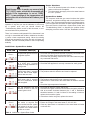
Heater Shutdown
1. Turn the thermostat dial to the lowest setting.
2. If the heater is running let it shut down first.
3. Turn off all electrical power to the heater or unplug the
power cord from the receptacle.
4. a) For WDER 2000N controls, press the gas control
switch located on the top of the control. It will automatically turn to the “OFF” position.
5. Turn the manual gas supply valve to the water heater to
the “OFF” position.
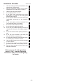
Water Heater Operation
Figure 22 shows the water heater's sequence of operation
when a call for heat is initiated. The ignition control module
will attempt to light the burner three times. If the ignition control does not detect ignition it will enter lockout mode and
flash the error code.
Putting the Heater into Service
1. Turn the manual gas shut-off valve for the heater to the
“ON” position.
2. Turn the gas control switch to “ON”.
3. Follow the Lighting Instructions (Robertshaw) given on
the side of the water heater and also depicted in this
manual. See also “Gas Supply”, “Water Heater
Operation” and “Sequence of Operation”.
Temperature Adjustment
The temperature dial is adjusted to its lowest temperature position when shipped from factory.
• The temperature of the water can be selected by adjusting the temperature dial located on the front of the control (see Figure 20).
• The large arrow position of the thermostat is the preferred starting point.
• Each division on the thermostat dial represents a 3°C
(5°F) water temperature change.
CALL FOR
HEAT
Note: To avoid scald injury, set the control to the lowest setting that will supply your hot-water needs.
There is a hot-water scald potential if the thermostat is set
too high. In households with children, disabled or the elderly, select a lower temperature setting. Tempering valves
(mixing valves) for reducing point-of-use water temperatures are available and may be required by your local
authority. Consult a licensed plumber or your local plumbing
authority.
WARNING
Risk of scalding
Hot water can produce third degree burns
in 6 seconds at . . . . . . . .60°C (140°F)
in 30 seconds at . . . . . . .54°C (130°F)
in 5 minutes at . . . . . . . . .49°C (120°F)
CONTROL CHECKS TO
ENSURE PRESSURE
SWITCH IS OPEN
BLOWER IS
ENERGIZED
CONTROL CHECKS TO
ENSURE PRESSURE
SWITCH CLOSES
INDICATING BLOWER
IS OPERATING AND
THERE ARE NO
VENTING BLOCKAGES
(INLET OR OUTLET)
IGNITER IS
ENERGIZED AND MAIN
VALVE IS OPENED
MAIN BURNER ON AND
THE FLAME IS
SENSED BY CONTROL
MAIN BURNER
CONTINUES TILL THE
WATER IN THE TANK
REACHES
THERMOSTAT
SETTING
MAIN BURNER SHUTS
OFF. BLOWER
CONTINUES FOR A
POST PURGE TIME
Figure 22 Sequence Of Operation
– 23 –
Lighting Instructions (White-Rodgers Intelli-VentTM)
– 24 –
CAUTION:
Read before proceeding. If you do not follow
these instructions exactly, a fire or explosion
may result, causing property damage, personal injury or loss of life.
Gas Control/Thermostat
Alternatively, this heater may be equipped with the WhiteRodgers Intelli-VentTM gas control/thermostat and a hot-surface igniter. This control is a combination gas valve, thermostat and ignition controller for use on this power vented
water heater. The valve contains a microcomputer that
supervises the ignition sequence and monitors the temperature settings and operation of the heater. The computer
also monitors the flammable vapour safety features of this
heater.
This heater is equipped with a White-Rodgers Silicon
Nitride Igniter system that automatically ignites the
burner. Do not attempt to light this heater manually with
a match or flame-producing device.
Putting the Heater into Service
1. Turn the manual gas shut-off valve for the heater to the
“ON” position.
2. Follow the Lighting Instructions (White-Rodgers) given
on the side of the water heater and also depicted in this
manual. See also “Gas Supply”, “Water Heater
Operation” and “Sequence of Operation”.
3. Upon start up all the indicator lights on the front of the
control will come on and then turn off. This indicates
that the control has completed a self-diagnostic test and
is ready for operation.
Note: If any of the indicator lights remain on, this indicates
a system fault that needs correcting. See the “System Error
Codes” and “Troubleshooting Guide (White-Rodgers)” for
corrective action.
Temperature Adjustment
The control is adjusted to its lowest temperature setting
(approximately 21°C (70°F)) when shipped from factory.
The temperature of the water can be selected by using the
temperature adjustment buttons on the front of the gas control (see Figure 18) as follows:
1. “Wake up” the temperature indicators by holding down
both the “COOLER” and “HOTTER” temperature adjustment buttons at the same time for one second. One or
two of the temperature indicators will light up. After 30
seconds, if no other buttons are pushed, the control will
go back to “Sleep” mode and both buttons will again
have to be pressed to see the water temperature setting.
2. Release both of the temperature adjustment buttons.
3. The current water temperature setting will be indicated.
See Table 3 for an explanation of the temperature indicators.
a. To decrease the temperature press and release the
“COOLER” button once. The temperature indicators
will now display the new temperature setting. Press
and release the “COOLER” button until you have
reached the desired setting.
b. To increase the temperature press and release the
“HOTTER” button once. The temperature indicators
will now display the new temperature setting. Press
and release the “HOTTER” button until you have
reached the desired setting.
Note: Holding down the button will not continue to lower the
setting. The button must be pressed and released for each
temperature change desired.
Note: To avoid scald injury, set the control to the lowest setting that will supply the hot water for your needs. Refer to
Table 3 to determine the approximate temperature setting,
and the approximate time for scald injury at that temperature.
4. When you have completed setting the control wait 30
seconds for the temperature indicators go off and the
control to enter “Sleep” mode.
DISPLAY
APPROXIMATE
TEMPERATURE
°C (°F)
21°C (70°F)
(VACATION)
43°C (110°F)
TEMPERATURE
INDICATORS
46°C (115°F)
49°C (120°F)
52°C (125°F)
TEMPERATURE
ADJUSTMENT
BUTTONS
54°C (130°F)
57°C (135°F)
60°C (140°F)
63°C (145°F)*
65°C (150°F)*
71°C (160°F)*
FLASHING
* These settings are not available on Hi-input models.
Figure 23 Temperature Indicators and Adjustment
Table 3
– 25 –
Temperature Settings
WARNING
Scald burns occur in under one second with
71°C (160°F) water, which this thermostat will
deliver if the temperature is set at “VERY
HOT”. Lower settings of the temperature will
reduce the risk of scald and will reduce your
fuel bill.
Note: All the temperature indicators will be off during normal
operation. If any time you see the indicators on, there may
be a system error and you should consult the
“Troubleshooting Guide” section of this document, or contact a trained service professional.
Heater Shutdown
1. Turn off all electrical power to the heater or unplug the
power cord from the receptacle.
2. Turn the manual gas supply valve to the water heater to
the “OFF” position.
System Error Codes
The computer inside the gas control monitors the ignition
sequence, temperature settings and overall operation of the
heater. If any of these parameters does not operate properly the computer will shut down the water heater and flash an
error code. See the “Intelli-VentTM System Error Codes” and
“Troubleshooting Guide” to diagnose the problem before
attempting corrective action. See also “Resettable Lockout”.
There is a hot-water scald potential if the thermostat is set
too high. In households with children, disabled or the elderly, select a lower temperature setting. Valves for reducing
point-of-use temperature by mixing hot and cold water are
available. Consult a licensed plumber or the local plumbing
authority.
Intelli-VentTM System Error Codes
SYMPTOM
Error 1
Error 2
Error 3
Error 4
Error 5
Error 6
Table 4
CORRECTIVE ACTION
POSSIBLE CAUSE(S)
An open earth ground circuit to 1. Check that the earth ground conductor is properly connected at the
fuse box or breaker panel and the water heater.
the ignition system.
2. Check that the grounding conductors on the water heater are properly connected and secure.
The self diagnostic test detect- 1. Check for proper connection of the line neutral and line hot wires.
ed a wiring error, reversed 2. Check that the appliance is securely connected to earth ground.
polarity or a high resistance to
earth ground.
The pressure switch remained 1. The pressure switch wiring is incorrect.
closed longer than 5 seconds 2. The pressure switch is defective and must be replaced.
after the call for heat began.
Blower does not start.
The pressure switch remained 1. The pressure switch wiring is incorrect.
open longer than 5 seconds 2. The pressure switch tubing is not connected correctly.
after the combustion blower 3. Obstructions or restrictions in the water heater air intake or exhaust
was energized.
flue.
4. Check the high temperature limit switch.
The self diagnostic test has 1. Check that all wiring is correct and secure.
detected an error in the hot- 2. Disconnect the igniter connector and measure the igniter resistance
surface igniter circuit.
with an accurate ohmmeter between pins 1 and 2. Resistance
should be between 11.5 and 18.8 ohms. If the reading is incorrect,
replace the hot-surface igniter.
3. If the above checks are good, replace the control.
The maximum number of igni- 1. Ensure the igniter is positioned correctly.
tion retries or recycles has 2. Ensure the voltage to the water heater is 115-125 VAC.
been reached and the system 3. Clear any obstructions or restrictions in the water heater air intake
is in lockout for an hour. Cycle
or exhaust flue.
the power to the water heater
off and on to reset.
Intelli-VentTM System Error Codes.
– 26 –
SYMPTOM
Error 7
CORRECTIVE ACTION
POSSIBLE CAUSE(S)
The self-diagnostic test found 1. Cycle power to the water heater “OFF” for 10 seconds and then
a problem with the gas valve
back “ON”.
driver circuit.
2. If the above step did not clear the error, the control must be
replaced.
Error 8
The self-diagnostic test has 1. Cycle the external power “OFF” for 10 seconds and then back “ON”.
detected a problem with the 2. If the above step does not clear the error, the control must be
internal microcomputer.
replaced.
Error 9
The self-diagnostic test has 1. Cycle the external power “OFF” for 10 seconds and then back “ON”.
detected a problem with the 2. If the above step does not clear the error, the control must be
internal circuit.
replaced.
Error 10
Error 11
Error 12
Error 13
Flame signal sensed out of 1. Insure flame sensor ceramic insulator is not cracked.
proper sequence.
2. Turn power off for 10-20 seconds, and then on again to clear the
error code.
3. Replace the control.
The high temperature thermal 1. Turn the power off for 10-20 seconds then on again to clear the
cutoff is open.
error code.
2. Replace the control.
The self-diagnostic test has 1. Make sure that there are no objects leaning against the front of the
detected one of the temperacontrol.
ture adjust buttons stuck 2. Lightly press and release each of the buttons once.
closed.
3. If the above actions do not clear the error, the control will continue
to regulate water temperature at the last setting, but you will not be
able to change settings unless you replace the control.
The self-diagnostic test has 1. Turn the power off for 10-20 seconds then on again to clear this
detected that the water temerror code.
perature sensor is either open 2. If no wiring problems are found the control must be replaced.
or short circuited.
Table 4 (cont’d) Intelli-VentTM System Error Codes.
– 27 –
V) OPERATION
Performance Checks
VI) SERVICE AND MAINTENANCE
Burner Manifold Pressure
The burner operates at a manifold gas pressure of 3.5 in.
w.c. (0.9kPa) for natural gas and 10.0 in. w.c. (2.5kPa) for
propane gas. A 1/8” NPT port is provided on the gas valve
control for connection to a gauge to measure the pressure
(See Figure 20). The control valve has an internal pressure
regulator. Do not confuse the manifold pressure with the
supply inlet pressure. Return port plug upon completion of
tests.
Checking Input
Never exceed input shown on the rating plate. Ask your gas
supplier for the heating value of the gas you are using.
Check the input by ”clocking” the gas meter. Make sure no
other appliances are operating when the test is being done.
To ensure accuracy, clock enough gas so that the time is
greater than 60 seconds. Use the following formula to check
input. Check that your gas pressures are as previously stated.
Input in BTU/Hour =
Gas Heating Value* x Cubic Feet/Meters clocked
Seconds clocked/3600
*Gas Heating Value in BTU/cubic feet or cubic meters
1 cubic meter = 35.31 cubic feet
This section describes the routine service instructions to
properly maintain your heater and venting system.
Not Enough or No Hot Water
• Check that the water heater is operational.
• Check that the thermostat is set high enough.
• Check that you have not just run out of hot water due to
heavy demand. If this is a routine problem, it may indicate an under-sized water heater.
• Have your gas company check input rate and water
heater operation.
• The ECO may have tripped open (LED indicator on constantly). See ECO below.
Energy Cut-off Control (ECO)
This water heater is equipped with a control that has a built
in ECO (Energy Cut-Off). The ECO will shut the gas off,
should the outlet water temperature exceed 93° (200°F). If
the ECO has tripped, the entire gas control must be
replaced. For gas control replacement, contact your local
gas utility, or a qualified service technician. The replacement control must be an identical model to the control that
has been removed.
Checking burner flame
SuperflueTM Water Heaters uses a cast iron burner. Access
the burner by lifting off the outer gas door and sliding open
the inner door located at the bottom of the water heater.
• For units with cast iron burners, the flame presentation
should be as shown in Figure 24. Adjustment is possible by changing the air shutter position on the burner
inlet. If the flame needs adjusting, loosen the two
screws and move the shutte (see Figure 25). If it is too
far open, the flame will lift or will be noisy; if it is closed
too far, the flame will be luminous and yellow. Once
proper flame is obtained, tighten the screws to secure
the air shutter.
Important: Always return the burner doors to their original
position.
AIR SHUTTER ADJUSTMENT
FOR CAST IRON BURNER
PRIMARY AIR
BLUE TIPS
LIGHT BLUE INNER
CONES ARE SATISFACTORY
INCORRECT
FLAME LAZY
YELLOW
CLOSED
OPEN
CORRECT FLAME
SOFT BLUE
Figure 24 Flame Characteristics
Figure 25 Cast Iron Burner
– 28 –
GOOD BLUE FLAMES
Water is Too Hot
• Check that thermostat setting is not too high.
• Water heaters used for dishwashers, space heating or
laundry facilities generally require higher temperatures
than domestic use. Install anti-scald tempering valves
as instructed in the safety warnings.
• See also “Temperature Regulation”.
• If the problem persists, contact your dealer or gas supplier.
Hot Water Odour
On occasion, and depending on your location, hot water
may develop a strong odour. This can be especially problematic in regions where the water contains some sulphur,
which results in hot water having a “rotten egg” smell.
If this occurs, drain the system completely, flush thoroughly
and refill. If the problem persists, the anode rod may need
to be changed from magnesium to one made of aluminum.
In certain cases chlorination and flushing of the water heater
may be required. Contact you dealer or water supplier.
Discoloured Water
• Water rich in iron or other minerals can produce red or
brown staining. Heating water generally worsens this
situation.
• Black water can be an indication of organic contaminates in the water supply. This can be problematic in
areas where the water is obtained from surface or contaminated sources. Organic particles can develop bacterial growth, causing potential health hazards. Contact
your water supplier for proper filtration or water conditioning equipment. For bacterial problems contact your
local health authority. See also “Hot Water Odour”
• A sudden appearance of rusty water can indicate the
anode rod has been depleted. The remaining steel core
wire may be corroding, releasing iron particles into the
water. Inspect and replace as necessary.
Water Heater Makes Noise
• During start up or under heavy use, condensation can
drip on the burner causing a sizzling noise as the water
is evaporated. This is normal and will stop once temperatures rise.
• Sediment, sand or scale can accumulate resulting in
“rumbling” noises. Water heaters need to be flushed
regularly to minimize buildup. Severe accumulations
can cause premature failure of the water heater and will
void the warranty.
• Vent piping can vibrate if it is not supported properly.
Ensure hangers and vibration isolators are properly
installed.
Condensation
Water vapor in the flue gases can condense on the cooler
surfaces of the water heater, especially during the start of a
cold tank, during heavy use, or if the water heater is undersized. Condensation can also be produced in the vent piping if the vent piping becomes chilled (e.g. going through
unheated areas) or if the dilution air is very cold.
Condensation may give the false impression that there is a
tank leak as significant amounts can drip out of the bottom
of the water heater. Once the water heater is operating at
normal temperatures tank condensation should disappear.
See “Venting” section for dealing with condensation in the
vent piping.
Anode Maintenance
Your water heater has been supplied with an anode rod that
protects the tank from corrosion. As the rod works, it slowly
dissolves over time and must be replaced when it becomes
totally consumed. Depending on water conditions, an anode
can last several years. Most localities treat their water,
which can have significant effect on the life of your heater.
Water conditioning such as over softening can accelerate
the rate at which the anode rod is consumed. Rapid depletion can leave a heater unprotected causing a premature
failure. As with any water heater, it is good practice to check
the anode annually to see if it needs replacing (Figure 1,
Item No. 15).
To
•
•
•
•
inspect or change an anode:
turn off the water heater
close the cold inlet supply valve
open a hot water tap supplied by the heater.
drain the water heater enough to empty the piping system.
• using a 1 1/16” socket, remove anode and inspect or
replace as required.
• refill system with water and restore water heater to
operation.
Warning: Operating a water heater without an actively
working anode rod will void the warranty.
Tank Flushing
Periodically (monthly) drain approximately 8 liters (2 gallons) from the tank through the drain valve. This will minimize sediment buildup on the tank bottom.
Caution: WATER WILL BE HOT.
If scale removal is being considered, contact your dealer for
proper procedures. DO NOT USE HYDROCHLORIC ACID
(HCL) based cleaners. Thoroughly flush after any chemical
cleaning.
Extended Non Use Service
Hydrogen gas can be produced by water heaters in service
but on standby for long periods of time (generally two weeks
or more). See safety warnings in the front of the manual.
Hydrogen gas is extremely flammable. Use caution in opening faucets.
– 29 –
Relief Valve Check
WARNING
•
•
•
•
Explosion Hazard
If the temperature and pressure relief
valve is dripping or leaking, have a
licensed plumber repair it.
Do not plug valve.
Do not remove valve.
Failure to follow these instructions can
result in death or an explosion.
Inspect the relief valve annually to ensure proper operation.
This involves opening the valve to check that it is flowing
freely and that there are no blockages. Provide a bucket or
drainage for the expelled water. Lift the lever and let it snap
shut. The water should stop instantly.
Temperature and Pressure
Relief Valve
Manual Relief Valve
Vent Maintenance
• Inspect the venting system periodically (minimum twice
annually) to make certain that the vent passageways,
vent terminal and blower assembly are free and unobstructed. Ensure that any condensate is draining freely.
Clean as necessary.
• Inspect the vent piping, elbows and connections for
signs of stress cracking or deterioration. Make certain
the venting is free to move and that all pipe hangers and
isolation supports are properly positioned and securely
attached. Replace any broken components and rectify
any installation problems.
• In areas that have a high level of airborne particulate
(e.g. lint, sawdust, process smoke, laundry areas, etc.)
inspection and cleaning may need to be done more frequently. This can be problematic, especially where condensation is present, as particles can adhere to the
venting surfaces. Particles, especially lint can also clog
the vent blower wheel. These conditions can reduce the
venter performance resulting in nuisance failures.
• Inspect the flue collector area for signs of corrosion.
This can be an indication of contaminated air, a wet
environment, poor burner set up, or high levels of condensation occurring at the flue collector. Determine and
correct any poor operating conditions.
Burner Maintenance
Annually inspect the burner and combustion chamber area
to ensure that no debris has fallen on the burner and that no
foreign material has found its way into the combustion
chamber. Observe the flame for proper operation.
ALWAYS KEEP THE AREA AROUND THE WATER
HEATER CLEAR OF COMBUSTIBLE MATERIALS.
NEVER RESTRICT THE FLOW OF AIR TO THE WATER
HEATER.
Discharge line to drain
Figure 26 T&P Valve Test
Warning: WATER WILL BE HOT and water flow can be
forceful. If the valve does not function properly, it must be
replaced.
In systems where the relief valve discharges periodically,
this may be due to thermal expansion or to a thermostat that
is operating at too high a temperature. In a closed water
system, an expansion tank may be required Contact your
local plumbing inspector. For a malfunctioning thermostat,
contact your gas supplier.
Manually operate the temperature and pressure relief valve
at least once a year to make sure it is working properly (see
Figure 26). To prevent water damage, the valve must be
properly connected to a discharge line that terminates at an
adequate drain. Standing clear of the outlet (discharged
water may be hot), slowly lift and release the lever handle
on the temperature and pressure relief valve to allow the
valve to operate freely and return to its closed position. If the
valve fails to completely reset and continues to release
water, immediately shut off the manual gas valve and the
cold-water inlet valve and call a qualified service technician.
AIR PRESSURE
TUBING
MOTOR
VENTILATION
OPENINGS
DRAFT
DIVERTER
AIR INTAKE
OPENING FOR
DRAFT DIVERTER
BLOWER
MOTOR
LIMIT
SWITCH
LIMIT
SWITCH
WIRES
Figure 27 Blower Maintenance
– 30 –
VII) COMBO HEATING
This section serves as a guide for the installation and use of
“Combo” heating systems utilizing a domestic water heater
that has been specifically approved for such use. It is written for those knowledgeable in the required trades and professionals involved in the design and installation of Combo
Heating Systems.
It is the responsibility of the installer/designer to follow
all applicable codes to ensure the effectiveness and
safety of the installation.
System Requirements
The following requirements must be met for the installation
of Combo Heating Systems:
1. All components used for the distribution of water in the
heating loop must be suitable for potable water. These
include all piping, fittings, solder and fluxes, pumps for
circulation of water, valves, etc.
2. The water heater must not be connected to a hydronic
heating system that has been used previously.
3. No boiler treatment chemicals of any kind shall be introduced into the system.
4. The Combo System components must be selected and
sized to meet and maintain the total calculated
demands for both domestic service hot water and space
heating requirement. The sizing and installation must be
performed in accordance with good engineering practice such as “ASHRAE Handbooks”, HRAI,
“Hydronics Institute Manuals”, CGA B149, NFPA 54,
ANSI Z223.1, CSA F280, National/Provincial
Building Codes, CSA C22.1, ANSI/NFPA 70, CSA
B51 and/or codes having jurisdiction.
5. The air handler (fan coil) and/or the circulating pump in
a baseboard hydronic loop will require a dedicated
120V circuit. This must be provided and identified for
this purpose.
6. All piping between the water heater and the air handler
or hydronic baseboard loop must be adequately insulated to reduce heat loss.
7. If the local jurisdiction requires a back-flow preventer in
the cold water line, an expansion tank of adequate size
must be installed.
8. "Combo" Heating Systems require higher water temperatures than other applications. When the system is
used to supply water for Combo Heating applications, a
means, such as mixing valve, must be installed to temper the water in order to reduce scald hazard potential
(see Figures 28 & 29).
– 31 –
AIR HANDLER
Figure 28 Combo Heating - Air Handler
FLOW CONTROL
WATER
HEATER
CHECK
VALVE
CIRCULATOR
HOSE BIB
(OPTIONAL)
Figure 29 Combo Heating - Baseboard
– 32 –
RETURN
RETURN
SUPPLY
H
SUPPLY
HOSE BIB
(OPTIONAL)
DRAIN PURGE VALVE
EXTERNAL
CIRCULATOR
C
M
300mm (8 in.)
MAX.
INTERNAL
CIRCULATOR
WATER
HEATER
CHECK
VALVE
IF USED CHECK VALVE
REQUIRES EXPANSION TANK
MIXING
VALVE
HYDRONIC BASEBOARDS
(SERIES CONNECTED SHOWN)
FLOW CONTROL
COLD INLET
300mm (8 in.)
MAX.
H
BASEBOARD PIPING OF
GSW POWER-VENTED
GAS-FIRED WATER
HEATERS (SIDE-TAPPED)
EXPANSION TANK
(OPTIONAL)
HOT WATER TO
HOUSE FIXTURE
IF USED CHECK VALVE
REQUIRES EXPANSION TANK
C
M
COLD SUPPLY
SIDE-TAPPED PIPING OF GSW
POWER-VENTED GAS-FIRED
WATER HEATERS (INTERNAL
OR EXTERNAL CIRCULATOR)
MIXING
VALVE
HOT OUTLET
HOT WATER TO
HOUSE FIXTURE
COLD SUPPLY
EXPANSION TANK
(OPTIONAL)
Maintenance
The installation and maintenance of the water heater must
follow all of the instructions described in sections I to VII of
this manual. Heater failure that is a result of the heating system is not covered by warranty.
COLD INLET
Fan Coil
The following is a list of requirements for the installation of
the heating loop to the water heater (see Figure 28).
1. Install shut-off valves and unions so that the water
heater can be isolated from the heating module should
servicing of the water heater become necessary.
2. Install a drain valve at the lowest point of the heating
loop so that water can be drained from the heating module without affecting the water heater.
3. If the air handler does not have a venting means at the
highest point of the piping arrangement, install an air
bleed at the highest point of the plumbing arrangement.
Baseboard Radiator Heating
The following is a list of requirements for the installation of
the heating loop to the water heater (see Figure 29).
1. Install shut-off valves and unions so that the water
heater can be isolated from the heating module should
servicing of the water heater become necessary.
2. A drain valve must be installed at the lowest point of the
heating loop so that water can be drained from the heating module without affecting the water heater.
3. Install air bleed valves at the highest points to purge air
from the system.
HOT OUTLET
Installation
The heating mode may be one of the following options:
A A fan coil (air handler)
B A hydronic baseboard (finned tube) loop/In-floor heating
VIII) TROUBLESHOOTING GUIDE
SUPERFLUETM
Note: Troubleshooting must be done by qualified service personnel familiar with the start up and check out procedure. See
also Sequence Of Operation (Figure 22).
STEP
CHECK THAT:
POSSIBLE PROBLEM
CORRECTION
1.
All steps on installation check
list have been followed
Incomplete installation
Review installation check list
2.
Gas supply matches heater
rating plate
Wrong gas / Wrong heater model
Match gas to heater type
3.
Gas supply is “ON”
Gas control is “ON”
No gas
- Turn on gas supply
- Check and adjust pressure
accordingly
4.
Heater is plugged into properly
fused circuit
- No power
- Incorrect polarity at power
source
- Check power supply
- Check fuses
- Plug in heater
5.
Thermostat is set to call for heat Thermostat set too low
Rotate dial to higher setting
6.
Gas control performs start up
diagnostic, LED flashes 3-4
times
- Gas control may be damp from
excessive humidity or condensation. Steady red LED light may
show on
- Continuous flashing red light
indicates safety lockout.
- Steady red LED light, possible
Energy Cut-Off (ECO) failure
from excessive water temperature, power surge or internal failure
- Disconnect power, remove safety cover and dry control see
Figure 20
- Incorrect or broken wire connection
- Blower defective
- Air pressure switch stuck closed
- Correct wiring conditions
-
7.
Power vent blower starts
- Replace blower*
- Replace pressure switch*
8.
Air pressure switch closes
(with sufficient vent draft)
-
9.
High limit switch closed (with
normal operating temperatures)
- Switch opened from excessive
vent temperature due to over-firing, flue collector blockage or
insufficient air supply
- Faulty switch
- Check and adjust firing rate
- Remove blockages
- Correct air supply conditions
- No power to igniter
- Check power supply to control
and igniter
- Disconnect power, wait for 10
sec. and re-energize
- Clear away debris
- Replace igniter
- See step 8
- See step 9
10.
Igniter energizes
Vent piping blocked or frozen
Vent piping too long
Blower wheel clogged
Pressure tube pinched or broken
Faulty pressure switch
- Disconnect power, wait 10 sec.
and re-energize
- Continue troubleshooting to find
source of failure
- Replace control*
- Flashing red LED light from:
- debris fallen on igniter or flame
rod
- igniter cracked or broken
- Air pressure switch open
- High limit switch open
– 33 –
Remove blockage
Reduce vent length
Clean wheel of dirt and debris
Correct condition
Replace pressure switch*
- Replace switch*
STEP
11.
CHECK THAT:
Gas valve opens, main burner
comes on
POSSIBLE PROBLEM
- Poor electrical connection on
control
- Flashing red LED light from:
insufficient gas pressure
- flame rod out of position
CORRECTION
- Check power supply and terminal connections
- Correct gas supply and burner
manifold pressures
- Reposition rod (rod tip should be
level with or slightly above the
top of the burner)
- flame rod oxidized (low signal) or - Unplug flame sensor wire and
broken (no signal)
connect micro amp meter.
Current should be greater than
0.7 micro amps. Remove oxidation (if present) with steel wool.
Replace rod if broken or signal
insufficient.
- Safety shut down by pressure
- See above information on presswitch or high limit switch.
sure switch or high limit switch
Blower continues to run but
- Check for debris that have may
heater will not operate
entered combustion chamber or
venting
– 34 –
White-Rodgers Intelli-VentTM
SYMPTOM
POSSIBLE CAUSE(S)
CORRECTIVE ACTION
BLOWER WILL NOT
START.
1. No Power to unit.
2. Thermostat setting too low.
3. Defective air pressure switch (must be
open at start-up before blower is energized).
4. Defective blower.
5. Disconnected or loose wire.
6. Control locked-out.
1. Plug in power cord, check fuses/supply
voltage.
2. Increase thermostat temperature setting.
3. Replace air pressure switch.
4. Replace blower.
5. Repair/reconnect wires.
6. Reset – determine cause of lockout.
1. Air pressure switch not closing due to
insufficient draft - check for:
1. Determine cause of insufficient draft.
Check draft with manometer at pressure switch (refer to Table 2 for minimum acceptable draft settings).
a) remove blockage,
b) reduce vent length/increase vent
size,
c) clear termination of snow/ice,
d) clean blower wheel.
2. Reconnect or replace pressure sensing
tubing.
3. Replace defective pressure switch.
4. Determine cause of overheating check
for: overfiring, insufficient air supply,
high ambient air temperature (once
activated high limit must be replaced).
BLOWER RUNS
CONTINUOUSLY.
HOT SURFACE IGNITER
NOT GLOWING
FOLLOWING WARM-UP
PERIOD.
a) vent piping blocked,
b) piping length too long,
c) frozen vent termination,
d) clogged/dirty blower.
2. Disconnected, torn or blocked pressure sensing tubing from air pressure
switch to blower housing.
3. Air pressure switch not closing due to
defective switch.
4. High limit switch open due to excessive
vent temperature or defective switch.
1. 120VAC polarity reversed at 120VAC
outlet receptacle.
2. Defective hot surface igniter.
3. Defective Control.
1. No gas supply.
2. Gas control switch in “OFF” position.
3. Insufficient gas supply.
4. Incorrect manifold gas pressure.
CONTROL LOCKED-OUT.
CONTROL LOCKED-OUT.
*SOLID GREEN LED.
5. Incorrect gas type.
6. Defective igniter/loose or disconnected
wire.
7. Improperly positioned, dirty, or defective flame rod/loose or disconnected
wire.
8. Burner orifice clogged.
9. Blocked water heater flue.
10.Defective control.
1. Internal control fault.
2. ECO failure – excessive water temperature.
3. Excessive humidity/damp environment.
– 35 –
1. Reverse polarity at 120VAC outlet
receptacle.
2. Replace igniter (Check for 120VAC
across I1 & I2, Robertshaw only).
3. Replace control.
1. Check/turn on gas supply.
2. Turn control switch to “ON” position
(Robertshaw only).
3. Ensure correct supply pressure for gas
type (Nat Gas 7.0 in. w.c. (1.74 kPa))
(Propane 11.0 in. w.c. (2.74 kPa)).
4. Check/adjust for correct manifold gas
pressure (NG 3.5 in. w.c.(0.87 kPa)),
(Propane 10.0 in. w.c. (2.49 kPa)).
5. Ensure correct gas type for water
heater model.
6. *Replace defective igniter/reconnect
wiring.
7. *Reposition, clean, or replace defective
flame rod/reconnect wiring.
8. Remove obstruction.
9 Remove blockage/clean flue.
10.Replace Control.
* See Figure 1
1. Replace control.
2. Replace control.
3. Allow control to dry.
*Note: Items that are damaged by power surges, improper gas pressures, freezing, flooding or improper handling,
installation or over-firing are not covered by warranty.
GSW Water Heating
599 Hill Street West
Fergus, ON Canada N1M 2X1
Should you have any questions please
Email us at [email protected]
or
Visit our websites: www.gsw-wh.com
or
www.johnwoodwaterheaters.com
or
Call our Technical Support line at
1-888-GSW-TECH (479-8324)
INSTALLATION RECORD
This water heater is protected by a multi-year warranty against leaks.
Record key data here for future reference and prompt service
INSTALLED BY:
INSTALLATION DATE:
LOCATION OF GAS SHUT-OFF VALVE:
MODEL NUMBER:
SERIAL NUMBER:
– 36 –
LIMITED WARRANTY
See Rating Label Serial Number prefix for
Warranty Code.
Warranty Code: P R S T U V W Y
Warranty Years: 3 5 6 7 8 9 10 12
RESIDENTIAL STORAGE TANK TYPE WATER HEATER FOR INSTALLATION IN A SINGLE FAMILY DWELLING
A. WHO IS COVERED.
GSW WATER HEATING AND ITS SUPPLIERS, (herein collectively referred to as “Manufacturer”) warrants only to the
original consumer purchaser (hereinafter “Owner”) of the water heater, within the boundaries of continental United States,
or Canada, or their territories, so long as he or she continuously occupies the single family dwelling in which this water
heater is initially installed for the period specified below. This warranty is not transferable. This warranty is reduced to one
year if the water heater is used in a commercial, or industrial application, or if the water heater is used to supply more than
one dwelling unit. Consumers must retain point-of-sale proof of purchase to validate warranty entitlement.
B. WHEN IT IS COVERED.
The water heater is warranted only when it is installed, operated and maintained in accordance with the printed instructions accompanying the water heater. The water heater shall/must be installed in such a manner that, if the tank or any
connection thereto should leak, the resulting flow of water will not cause damage to the area in which it is installed. The
water heater’s temperature and pressure relief valve must be piped to the nearest drain to avoid damage in the event the
valve is actuated. For detailed instructions read the manual accompanying the water heater and review drawings in the
manual.
C. WHAT THE MANUFACTURER WILL DO AND THE PERIOD OF COVERAGE.
1. The Inner Tank. If the inner tank leaks within the warranty period shown in the table at the top of this page after the
original installation, Manufacturer will furnish a new water heater of Manufacturer’s then prevailing comparable model.
If industry standards, regulatory changes, product improvements or product obsolescence prohibits Manufacturer from
furnishing an identical model replacement water heater under this warranty, the Owner will be furnished with a new
water heater of comparable capacity; however, the Owner will be charged for the additional value of the item(s) which
Manufacturer has incorporated in the replacement water heater. A prior authorization number must be obtained from
the Manufacturer before replacing the water heater. This warranty is limited to one replacement water heater at the
original installation site.
2. Component Part. If any component part other than the inner tank proves to Manufacturer’s satisfaction to be defective in material or workmanship within one (1) year, the Manufacturer will furnish the Owner with a replacement for the
defective part(s). This warranty is limited to one replacement component part for each original part.
3. Return of Defective Water Heater and Component Parts. Manufacturer reserves the right to examine the alleged
defect in the water heater or component part(s), and it will be the Owner’s obligation (See paragraph D.5) to return the
water heater and/or component part(s) to the Manufacturer.
a. When returning a water heater it must include all component parts and the data plate label.
b. When returning component part(s), they must be individually tagged and identified with the water heater’s product
number, model number, serial number, date of purchase and date of installation.
c. THERE ARE NO WARRANTIES WHICH EXTEND BEYOND THE DESCRIPTION ON THE FACE HEREOF. THIS
EXPRESS WARRANTY IS, WHERE PERMITTED BY LAW, IN LIEU OF AND EXCLUDES AND REPLACES ALL
OTHER CONDITIONS, WARRANTIES, GUARANTEES, REPRESENTATIONS, OBLIGATIONS OR LIABILITIES
OF THE MANUFACTURER OF ANY NATURE OR KIND, EXPRESS OR IMPLIED, HOWEVER ARISING
(WHETHER BY CONTRACT, CONDUCT, STATEMENT, STATUTE, NEGLIGENCE, PRINCIPLES OF MANUFACTURER’S LIABILITY, OPERATION OF LAW OR OTHERWISE) WITH RESPECT TO THE UNIT OR ITS FITNESS
FOR A PARTICULAR PURPOSE, MERCHANTABILITY, INSTALLATION, OPERATION, REPAIR OR REPLACEMENT. THE MANUFACTURER EXPRESSLY DISCLAIMS ANY AND ALL IMPLIED WARRANTIES. IN NO EVENT
WILL THE MANUFACTURER’S LIABILITIES EXCEED THE COST OF THE DEFECTIVE PART(S) OR UNIT.
D. WHAT THIS WARRANTY DOES NOT COVER.
1. The Unit must not be installed where water damage can result from a leak, while provision(s) shall be made for directing any water escaping from the Unit, to a properly operating drainpipe. As all units of this type may eventually leak,
you must protect against any potential water damage. The Manufacturer accepts no responsibility for such damage,
nor any incidental or consequential loss, nor damage(s) related thereto, suffered by the Owner of the Unit nor by any
third party.
2. Manufacturer shall not be liable under this warranty and this warranty shall be void and have no effect if the following
events occur:
a. The water heater or any of its component parts have been subject to misuse, alteration, neglect or accident; or
b. The water heater has not been installed in accordance with the applicable local plumbing and/or building code(s)
and/or regulations or in their absence, with the latest edition of the Natural Gas and Propane Installation Code,
and/or the Canadian Electrical Code; or
c. The water heater is not installed, operated and maintained in accordance with the Manufacturer’s instructions; or
– 37 –
d. The water heater or any of its component parts are damaged or fails from operation with an empty or partially
empty tank (such as, but not limited to elements burned out in a dry tank); or
e. The water heater or any part has been under water; or
f. The water heater is exposed to highly corrosive atmospheric conditions. No warranty extends, for example, and
without limitation of the foregoing, to Units exposed to: salts, chemicals, exhausts, pollutants or contaminants; or
g. The water heater is not continuously supplied with potable water; or
h. The water heater replacement is requested for reasons of noise, taste, odor, discoloration and/or rust; or
i. The water heater is operated at temperatures exceeding the maximum setting of the thermostat and/or high limit
control provided by the Manufacturer, or at water pressures exceeding the pressure reading stated on the Unit; or
j. The water heater is operated without an operating anode; or
k. The water heater is supplied or operated with deionized water; or
l. The water heater is removed from its original installation location; or
m. The water heater is installed outdoors (this water heater is intended only for indoor installation); or
n. The water heater is converted, or is attempted to be converted, from one voltage or wattage to another, if an electric water heater, or from one type gas to another, if a gas water heater; or
o. The water heater has not been fired at the factory rated input and fuel for which it was factory built; or
p. The water heater or any of its component parts fail due to sediment build-up; or
q. The water heater does not have installed a properly operating temperature and pressure relief valve, certified to
ANSI Z21.22/CSA “Requirements for Relief Valves for Hot Water Supply Systems”; or
r. The water heater or any of its component parts fail because of fire, floods, lightening, or any other act of God, or
any other contingency beyond the control of the Manufacturer; or
s. The water heater is installed in a closed system without adequate provision for thermal expansion.
3. Except when specifically prohibited by the applicable law, the Owner, and not the Manufacturer, shall be liable for and
shall pay for all charges for labour or other expenses incurred in the removal, repair or replacement of the water
heater or any component part(s) claimed to be defective or any expense incurred to remedy any defect in the product.
Such charges may include, but are not necessarily limited to:
a. All freight, shipping, handling and delivery costs of forwarding a new water heater or replacement part(s) to the
Owner.
b. All costs necessary or incidental in removing the defective water heater or component part(s) and installing a new
water heater or component part(s).
c. Any material required to complete, and/or permits required for, installation of a new water heater or replacement
part(s), and
d. All costs necessary or incidental in returning the defective water heater or component part(s) to a location designated by the Manufacturer.
4. The terms of this Limited Warranty cannot be modified by any person, whether or not he/she claims to represent or act
on behalf of the Manufacturer.
E. HOW THE ORIGINAL OWNER CAN MAKE A WARRANTY CLAIM.
1. The Owner should submit the warranty claim directly to Manufacturer’s Service Department, at the address or phone
number listed below, and Manufacturer will arrange for the handling of the claim.
2. Whenever any inquiry or request is made, be sure to include the water heater’s catalogue number, model number,
serial number, date of purchase, date of installation, and location of installation.
This warranty and the Manufacturer’s obligations shall be construed and determined in accordance with the laws of both the
Province of Ontario, and of Canada in force therein. This Warranty does not affect specific legal rights of a consumer under
applicable law, except to the extent that such rights may be waived or replaced, and the provisions hereof are deemed to be
amended to the extent necessary. The unenforceability of any provision, in whole or in part, of this Certificate shall not affect
the remaining provisions. Any and all repair and/or replacement of part(s) or Unit are the sole and exclusive remedy available
against the Manufacturer.
GSW Water Heating
599 Hill Street West
Fergus, ON Canada N1M 2X1
Should you have any questions please
Email us at [email protected] or
Visit our websites: www.gsw-wh.com or
www.johnwoodwaterheaters.com or
Call our Technical Support line at
1-888-GSW-TECH (479-8324)
GSW Water Heating is a division of A.O.Smith Enterprises Ltd.
– 38 –