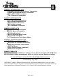
1
SHORTWAVE
CONVERTER KIT
Ramsey Electronics Model No.
SC1
Fascinating listening for all ages and abilities - tunes the
world from any standard AM broadcast receiver. Put
some ‘spark’ into that commute to work or that long trip,
listen to shortwave in your car!
•
Switch selectable for any two shortwave bands from 3 to 18
MHz - you pick the bands!
•
Works with any AM radio - car radios are ideal!
•
Tune from your regular radio dial - easily set station presets,
etc. on your existing radio.
•
Operates on 9 to 15 volts.
•
Listen to worldwide broadcasts in your car, boat, or home.
•
Very sensitive, works as well as thousand dollar receivers!
•
Great project for commuters and those who spend long hours
in the car or truck.
•
Clear, concise step-by-step instructions carefully guide you
to a finished kit that not only works - but you’ll learn too!
•
Add our case and knob set for a finished ‘Pro’ look. Cases
match all Ramsey products.
SC-1 • 1
RAMSEY TRANSMITTER KITS
• FM100B Professional FM Stereo Transmitter
• FM25B Synthesized Stereo Transmitter
• AM1, AM25 AM Transmitters
• TV6 Television Transmitter
RAMSEY RECEIVER KITS
• FR1 FM Broadcast Receiver
• AR1 Aircraft Band Receiver
• SR2 Shortwave Receiver
• AA7 Active Antenna
• SC1 Shortwave Converter
RAMSEY HOBBY KITS
• SG7 Personal Speed Radar
• SS70A Speech Scrambler
• SP1 Speakerphone
• WCT20 Wizard Cable Tracer
• PH10 Peak hold Meter
• LC1 Inductance-Capacitance Meter
RAMSEY AMATEUR RADIO KITS
• DDF1 Doppler Direction Finder
• HR Series HF All Mode Receivers
• QRP Series HF CW Transmitters
• CW7 CW Keyer
• CPO3 Code Practice Oscillator
• QRP Power Amplifiers
RAMSEY MINI-KITS
Many other kits are available for hobby, school, Scouts and just plain FUN. New
kits are always under development. Write or call for our free Ramsey catalog.
SC1 SHORTWAVE CONVERTER KIT INSTRUCTION MANUAL
Ramsey Electronics publication NO. MSC1 Rev. 1.3a
First printing: July 1992
COPYRIGHT 1993 by Ramsey Electronics, Inc. 590 Fishers Station Drive, Victor, New York
14564. All rights reserved. No portion of this publication may be copied or duplicated without the
written permission of Ramsey Electronics, Inc. Printed in the United States of America.
SC-1 • 2
Ramsey Publication No. SC1
Price $5.00
KIT ASSEMBLY
AND INSTRUCTION MANUAL FOR
SHORTWAVE
CONVERTER KIT
TABLE OF CONTENTS
Introduction to the SC1 ...........................4
What you can expect to hear ..................5
Parts list ..................................................6
SC1 Parts layout .....................................7
SC1 Circuit description ...........................8
SC1 Assembly instructions .....................9
Setting up the SC1 ..................................12
Setting your listening bands ....................13
Understanding what you're tuning ..........15
Schematic diagram .................................18
Ramsey Warranty ...................................19
RAMSEY ELECTRONICS, INC.
590 Fishers Station Drive
Victor, New York 14564
Phone (585) 924-4560
Fax (585) 924-4555
www.ramseykits.com
SC-1 • 3
INTRODUCTION
The Ramsey SC1 Shortwave Converter is perhaps one of the most
enjoyable, versatile and interesting radio kits you could ever build. And, since
it is exceptionally easy to build and use, it is a great kit for beginners.
Ramsey Electronics designed the SC1 especially for use with car radios. Its
flexible and practical features make it ideal for this kind of use and the
manual will explain why this is so. The other "ideal" receiver with which to
use the SC1 is a good quality AM-FM home stereo system. In fact, an SC1
converter has put fresh life into the stereo system in my own office. Even
though I've enjoyed a variety of shortwave and Ham receivers over the years,
there's nothing quite like smoothly tuning the BBC, Radio Moscow, VOA or
Paris on a quality stereo tuner and hearing it all as a big sound through highpower speakers! And you’ll have so much control over sound quality with
bass, treble, equalizing, etc.
QUESTION: What exactly is a "shortwave converter"?
ANSWER: Any receiver converter is a device which "force feeds" signals
from another frequency band into the antenna input line of a normally
complete, functioning receiver. Virtually any receiver can be converted to
receive other bands in this manner. The receiver functions as a tuneable "IF"
and its good circuit qualities carry over to the newly received frequency band
of interest. If a radio is considered to be a double conversion superhet, the
addition of a converter makes it a triple conversion superhet. Both car radios
and quality home stereos are ideal for shortwave conversion because of
their:
•
•
•
•
excellent sensitivity
sophisticated superhet, hi-fi receiver circuitry
smooth, accurate dial tuning
design for use with an external antenna
A car radio is designed to endure many bumps and engine noise. A home
stereo receiver or tuner is designed for maximum sound quality in AM-band
reception. Both are designed to be the best AM receiver circuits possible.
And since both rely on an external antenna, both are ready to use the SC1
Shortwave Converter!
A receiver designed for an external antenna is preferred for converter
operation over the typical portable or table radio with built-in antenna, since
you don't have to do anything within the radio itself for best shortwave band
performance. The SC1 may be used with a portable or table AM-band radio,
but you can expect a need for some internal connections to make sure that
the SC1 output "gets ahead" of the radio's built-in antenna. In these days
SC-1 • 4
when portable broadcast band radios are very cheap, or often available free
in various promotions, we can only suggest that you study how a particular
radio is designed and that you figure out how to get the RF output of the SC1
beyond the internal ferrite rod antenna of the AM radio. To get the most from
your SC1, we suggest that you plan to use it with a good quality AM radio
with an external antenna connection.
WHAT YOU CAN EXPECT TO HEAR
The SC1 is designed to let you easily tune in shortwave broadcasts from
around the world, using the dial of your existing AM radio for easy tuning.
These broadcasts are AM (Amplitude Modulation). You will also hear a
variety of other "interesting" sounds, but just remember that this receiving setup is designed for listening to AM style broadcast formats.
Morse code (CW) or teletype signals will probably sound like hisses or
buzzing noises. If a code signal really sounds "good", it's either because it is
being transmitted in AM-modulated form, or perhaps the signal is so close to
an AM broadcast carrier that the carrier acts as a "beat frequency
oscillator" (BFO). Even though this converter can let you tune through several
different Ham radio bands, the signals are not likely to be intelligible.
Reception of CW and SSB (single-sideband) signals requires the use of a
BFO. This is not a complicated feature, but it is beyond the purpose of the
SC1. (Hams and experimenters: please see the section for you at the end of
this manual.)
SC-1 • 5
PARTS SUPPLIED WITH THE SC1 KIT
CAPACITORS
1 4.7 or 5 pF disc [marked 4.7 or 5K] (C6)
2 100 pF disc [marked 100, 101, or 101K] (C7,C8)
2 470 pF disc [marked 470 or 471] (C2,C3)
5 .001 uF disc [marked .001, 102, or 1 nF] (C1,C4,C5,C9,C10)
2 .01 uF disc [marked .01, 103, or 10 nF] (C11,C12)
1 4.7 or 10 uF electrolytic (C13)
INDUCTORS
1 Shielded coil marked 42IF123 (L1)
1 Shielded coil marked 42EB (L2)
3 3.9 uH inductor [green body with a large silver band followed by orangegold-white-silver bands] (L3,L4,L5)
RESISTORS
2 470 ohms [yellow-violet-brown] (R4,R6)
2 1K ohms [brown-black-red] (R2,R5)
2 100K ohms [brown-black-yellow] (R1,R3)
SEMICONDUCTORS
3 NPN transistor type 2N3904 (Q1,Q2,Q3)
HARDWARE & MISC.
1 Ramsey SC-1 printed circuit board
2 RCA PC mount RCA jacks (J1,J2)
1 PC mount DC power jack (J3)
2 PC mount DPDT switches (S1,S2)
OPTIONAL
Matching case and knob set Ramsey model number CSC
SC-1 • 6
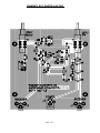
RAMSEY SC1 PARTS LAYOUT
SC-1 • 7
CIRCUIT DESCRIPTION
Q3 functions as part of a variable Colpitts oscillator which utilizes S2 and
jumper points A,B,C to setup a choice of preferred local oscillator
frequencies from 3 to 22 MHz. L2 and C10 may be replaced by a crystal for
tuning in a desired range 500 to 1600 KHz around the crystal oscillator
frequency.
C2,C3 and L3,L4 and L5 form a high-pass filter from the antenna to pass
shortwave signals only and to minimize strong local AM broadcast signals.
The antenna-filter network and the Q3 oscillator output are fed to the base of
mixer-amplifier Q2. The transistor output is fed to the RF input of a standard
550-1600 KHz AM broadcast band receiver. The receiver can detect and
amplify shortwave signals on frequencies which are either the sum or the
difference of the SC-1 oscillator frequency and the dial setting of the
receiver.
Our directions for adjusting the SC-1 assume a pattern of the received
frequency being the SC-1 oscillator ADDED to the tuning range of the AM
radio. For example, to receive 10 MHz WWV, the radio dial is set to 1000
KHz, and the SC-1 oscillator is set to 9 MHz Another way of viewing it is that
if the oscillator is set to 9 MHz, the receiver will tune 9.550 to 10.600 MHz (9
MHz plus the 550-1600 AM radio range) depending on how much the radio's
tuning overlaps the standard 550 KHz to 1600 KHz broadcast band.
The antenna RF input filter is broad-banded. There is no provision for preselecting any particular portion of the HF spectrum at either the input or
output of Q2. Therefore, occasional images from strong signal sources
should be anticipated. Generally, the reception of typical shortwave
broadcast stations fully overwhelms any image signal.
S1 serves two functions. In the "off" position, S1B connects the antenna jack
directly to the receiver jack, permitting normal AM broadcast reception. In the
"on" position, DC voltage is applied to the SC-1 circuitry and the antenna is
connected through the high-pass filter to Q2.
Q1 is connected with its emitter-base junction reverse biased, so that it
serves as a voltage regulator, limiting the voltage on its emitter to 7 volts and
enhancing the stability of the oscillator.
SC-1 • 8
RAMSEY SC1 KIT ASSEMBLY
In all PC board assembly steps, our word "INSTALL" means to do this:
• Insert the part, oriented or "pointed" correctly, into its holes in
the PC board.
• If helpful, gently bend the part's wire leads or tabs to hold it in
place, with the body of the part snugly against the top
side ("component side") of the circuit board.
• Solder ALL wires or pins of the part.
• Trim or "nip" all excess wire lengths extending beyond each
solder connection, taking care that wire trimmings do not
become lodged in solder connections.
In keeping with the Ramsey Learn-As-You-Build philosophy, the following
steps will comment on the why as well as the how-to. We know you want to
get it working quickly, but try to peek at the schematic circuit diagram from
time to time. Enough talk, let's get building!
❒
1. Install J3, the DC power jack.
❒
2. Install J1, the antenna or "RF input" jack.
❒
3. Install S1, the first of two DPDT push-style switches. These switches
fit the PC board only one way. Solder all six pins.
❒
4. Install C1, .001 uF (marked .001, 102, or 1 nF), the antenna coupling
capacitor.
❒
5. Install L3, the first of the 3.9 uH inductors, which have a green body
and are marked orange-gold-white.
❒
6. Install C2, 470 pF (marked 470 or 471).
❒
7. Install L4, another 3.9 uH inductor.
❒
8. Install C3, 470 pF.
❒
9. Install L5, the last of the 3.9 uH inductors.
❒
10. Install C4, .001 uF (marked .001, 102, or 1 nF). Look at the SC1
schematic diagram. You have already wired the entire high-pass filter
❒
11. Install transistor Q2, 2N3904. Press Q2's wire leads gently but firmly
into the three holes, making sure that the flat side is oriented correctly.
❒
12. Install R1, 100K ohms [brown-black-yellow].
SC-1 • 9
❒
13. Be certain to double check your component values, this will save
you a lot of problems! Now let's get back to building!
❒
14. Install R2, 1K [brown-black-red].
❒
15. Install R6, 470 ohms [yellow-violet-brown].
❒
16. Install C12, .01 uF (marked .01 or 103 or 10 nF).
❒
17. Install R5, 1K ohm [brown-black-red].
❒
18. Install C5, .001 uF (marked .001, 102, or 1 nF). C5 couples Q2 to the
PC board trace leading to the receiver jack.
❒
19. Install J2, the output jack to the AM receiver.
PROGRESS SUMMARY: You've done the hardest part (getting started!) and
are over half-finished with your SC1 PC board wiring. Transistor Q1 passes
shortwave signals from the antenna to your AM radio. Now, all we need is an
oscillator (Q3,L1 and L2, etc.), and some voltage regulation (Q1).
❒
20. Install transistor Q1, 2N3904. Observe correct position of the flat
side.
❒
21. Install C13, 4.7 or 10 uF, the ONLY electrolytic or "polarized"
capacitor in the SC1 kit. Electrolytic capacitors have a right and a wrong
way they can be installed. The PC board is marked with a '+' sign while
the capacitor is usually marked with its negative '-' side. Observe correct
polarity!
❒
22. Install C6, 4.7 or 5 pf (marked 4.7 or 5 K). This capacitor will inject
Q3's oscillator signal to the input of Q2, so that the AM radio can tune
the sum or the difference of shortwave signals and the oscillator
frequency.
❒
23. Install push switch S2.
❒
24. Install C10, .001 uF (marked .001, 102, or 1 nF).
❒
25. Install R3, 100K [brown-black-yellow].
❒
26. Install C11, .01 uF (marked .01 or 103 or 10 nF).
❒
27. Install transistor Q3, watch position of the flat side.
❒
28. Install C8, 100 pF (marked 100, 101, or 101K).
❒
29. Install R4, 470 ohms [yellow-violet-brown].
❒
30. Install C7, the other 100 pF capacitor.
SC-1 • 10
❒
31. Install C9, .001 uF (marked .001, 102, or 1 nF).
Installation of Q3 oscillator coils L1 and L2: The wiring of your SC1 is now
finished except for your own plans about how to use and tune it. If you
expect to exercise options other than our suggestions for basic shortwave
broadcast listening, read the information following the assembly directions
before proceeding. Otherwise, complete the following steps.
❒
32. Install L2, marked 42EB. Do not confuse it with the other shielded
coil. L2 is the coil used for tuning the lower shortwave frequency bands.
It fits the PC board holes only one way: you will notice one extra hole,
which is provided for using a crystal in place of L2 and C10.
❒
33. Coil L1, marked 42IF123, requires a simple modification before
installation. There is a small tubular capacitor visible in the plastic
bottom of the coil that needs to be removed, which is done by crushing it
with the tip of a small screwdriver or the point of a knife. It crumbles quite
easily and it is actually fun to be destructive for a change! Crush the
capacitor and install L1. It fits on the PC board in only one direction.
❒
34. The remaining three holes near L1 are for installation of a jumper
wire to determine L1's tuning range:
Jumper A to B to tune 10.7-18.3 MHz
Jumper C to B to tune 6.7-12.9 MHz
If you have little familiarity with shortwave bands, we suggest the C
to B connection to get started.
The PC board assembly of your Ramsey SC1 Shortwave Converter is now
complete. This is a good time for you or a friend to recheck your work,
retracing each of the preceding assembly steps. Watch for the quality of
solder connections and correct orientation of the three transistors.
SC-1 • 11
SETTING UP THE SC1 FOR A HOME STEREO SYSTEM:
❒
1. Make sure the stereo AM-FM receiver has provisions for attaching an
external AM antenna. Sometimes, the built-in antenna wires are
detachable from the rear-panel antenna terminals.
❒
2. Prepare a short coaxial cable with suitable connectors or wire ends to
make a neat connection between the SC1 and the receiver AM antenna
terminals.
❒
3. Provide a 9 to 12 volt battery power supply. A 9-volt battery snap
connector is easily wired in parallel with the 12-volt connector on the PC
board.
❒
4. Connect a suitable shortwave receiving antenna to the SC1 antenna
jack. 10 to 20 feet of hookup wire will do fine.
SETTING UP THE SC1 FOR AUTOMOBILE USE:
The 12-volt DC power connection for the SC1 is accomplished most easily
by the use of the Ramsey CLG-1 cigarette lighter cord or a similar cord from
Radio Shack. You may also make a permanent installation using the
appropriate coaxial style DC power plug to the SC1 and "hard" wiring into the
car's fuse block.
Some automobile ignition systems cause noise which needs to be
suppressed for satisfactory operation of ANY radio device. When using this
converter in a car, you may have to install a noise filter on your alternator, or
suitable resistor-type spark plug wires. A competent mobile CB radio shop or
technician can be helpful in such cases. Radio Shack carries a variety of
noise filters and eliminators.
The most common auto radio antenna connector is the Motorola style plug.
The cheapest and neatest antenna hookup for the SC1 is made from a maleto-female in-line extension cable. Radio Shack No. 12-1312 is a 24" length
with a plug at one end and an insulated jack at the other. Cut the cable in
half and solder RCA-type plugs to the two cut ends, using correct coax cable
preparation and soldering techniques. The new cable with the male Motorola
plug connects between the car radio and the SC1 receiver jack. The other
short cable permits a neat connection of the car radio antenna to the SC1
antenna jack. Before buying or cutting any cables, however, study your car
radio installation and how you will locate the SC1.
SC-1 • 12
SETTING YOUR LISTENING BANDS
The nice thing about the SC1 for beginners is that you'll hear some kind of
shortwave signals as soon as you hook it up to your AM radio and a suitable
antenna. As long as you wired it up right, your AM radio has no choice but to
tune shortwave! You can enjoy the SC1 without even knowing what
frequency you are hearing. Exactly which frequency band you are really
hearing is another question - and the topic of this section!
To adjust L1 and L2 for your desired listening range, you will need a plastic
alignment tool. If you do not have one and do not wish to buy one, a suitable
tool can be made by sanding the tip of a wooden matchstick, kabob stick, or
small plastic knitting needle. A metal screwdriver tip will not permit accurate
adjustment, since the metal itself will detune the coils.
•
If you know all about shortwave broadcasting, you'll be able to make
your own decisions on how to set up L1 and L2 for your choice of two 1
MHz SW bands selected by S2, tuned by the AM radio.
•
If you aren't familiar with shortwave broadcast band frequency
allocations but have and know how to use test equipment such as a
signal generator and frequency counter, you will be able to set up the
SC1 to tune exactly what you want.
•
If you are a newcomer with no knowledge of shortwave or any precision
test equipment, you can still adjust the SC1 to let you tune around your
chosen band on your AM-radio.
First, let's take a look at what is possible to hear on your SC1. The following
are the internationally-designated shortwave broadcasting bands:
A. Using L2 ("Night Listening") - S2 pushed IN:
4.750-5.060 MHz (Lower power,regional "tropical" broadcasting)
5.950-6.200 MHz (Late evening)
7.100-7.300 MHz (Late afternoon, early evening)
B.Using L1 with B-C jumper - S2 in OUT position:
9.500-9.900 MHz (Always "something" on, 24 hours a day!)
11.650-12.050 MHz (Generally good daytime broadcasting)
C. Using L1 with A-B jumper - S2 in OUT position:
11.650-12.050 MHz (Generally good daytime broadcasting)
15.100-15.600 MHz
17.550-17.900 MHz
SC-1 • 13
Notice that the 11MHz band is available in BOTH the B-C and A-C jumper
settings for L1. The higher frequency bands are intended primarily for
daytime broadcasting. Reception quality is very dependent upon atmospheric
propagation conditions.
Even though there is quite a sport and science to digging up exotic
broadcasts from hundreds of countries in any of the above bands,
newcomers will find more immediate satisfaction from setting up L1 for the 9
MHz (31 Meter) band, and L2 for 5.9 to 6.2 MHz. With this arrangement,
you'll easily find the "major" international broadcasts anytime you want to
listen. Especially strong signals include these, among others:
•
•
•
•
•
BBCLondon: an intelligent perspective on world affairs
RadioCanada International: editorial quality similar to the BBC
Radio Moscow: powerful signals, increasingly honest and open
Voice of America: VOA broadcasts are "aimed" outside the USA, but if
you're in the "path" you'll hear it loud and clear!
U.S. Armed Forces Radio-TV "Feed" Service: Master programming
source for the U.S. military radio - hear CBS-NBC-ABC-Mutual news on
all the same "channel", plus many other features and spots which give a
feel for how it's going with those in uniform.
You'll easily tune broadcasts from many other countries as well. As you
become more and more familiar with the world of shortwave broadcasting,
you'll be making your own choices on how best to set up the convenient
options possible with your SC1.
An easy way to adjust the SC1 is to use another shortwave radio to listen for
the SC1's strong oscillator signal. For eample, if you set L1 so that you hear
the signal at 9.0 MHz on another receiver, your SC1 is set to receive 9.5
MHz at 500 KHz, 9.6 at 600, 9.7 at 700, and so forth.
OPTIONAL CRYSTAL CONTROL
With S2 in the pushed-in position, the SC1 is designed so that L2 can be
easily replaced by a crystal. Install a crystal of your choice in the 3 to 10 MHz
range. An extra hole is drilled near the L2 mounting holes to make crystal
insertion easy. Consult the schematic diagram. Replace C10 with a jumper
wire. The received frequency will be the crystal frequency plus or minus the
AM radio dial frequency.
SC-1 • 14
UNDERSTANDING WHAT YOUR RADIO IS ACTUALLY TUNING
As mentioned in the SC1 circuit description, this converter is broadbanded,
meaning that there is no provision to pre-tune the antenna input to a
particular frequency band. This design poses little problem for casual
shortwave broadcast listening, but it would not be the right design for a
communications receiver relied upon for tuning weak, distant signals. At any
given time, your AM radio is actually giving you two shortwave frequencies at
the same time!
Let's say that you are listening to Radio Moscow on 11.840 MHz with your
radio dial set at 1000 KHz. This means that the SC1 oscillator (L1) is running
at 10.840 KHz. This means that your AM radio is also receiving the
difference of 10.840 MHz and 1000 KHz, which is 9.840 MHz, also a popular
shortwave broadcast band. It also means that you could hear the same
11.840 MHz broadcast with the SC1 oscillator tuned to 12.840 and that your
radio could also pick up signals on13.840 and so forth. You actually may use
this effect to your advantage in being able to tune in to two bands with one
oscillator setting!
NOTES FOR RADIO HAMS AND EXPERIMENTERS
The SC1 Shortwave Converter can be a fun "platform" for putting an extra
AM-radio set to work for listening to your favorite band. Brand-new AM-only
car radios pulled from new vehicles are easy and inexpensive to find. There
is ample room on the PC board for changes and add-ons of your own design,
but please be sure that you read and understand the Ramsey Kit Warranty
before undertaking any changes of the original circuit.
If you build a 455 KHz BFO for CW-SSB reception, its output may be
coupled to the output of Q2 and fed directly to the receiver antenna input. Or
you can design a BFO within the AM radio itself. There is also plenty of room
on the PC board for additional tuneable circuits, or you may wish a switching
arrangement for jumpers A-B and B-C.
If you are teaching a class on receiver fundamentals, the SC1 is easy to set
up to do some effective show-and-tell. In addition to the SC1, a 9 or 12-volt
DC supply, hi-fi or automobile receiver, and antenna, use the following for
your demonstration: solid-state signal generator (for BFO injection), a
Ramsey Frequency Counter (to display SC1 oscillator frequency), plus a test
signal of some kind such as a Ramsey QRP transmitter connected to a
dummy load. Your demonstration can teach the principles of mixing,
tuneable IF, what images are, and BFO injection.
SC-1 • 15
If you've enjoyed building this kit, why not consider some other fine Ramsey
kits? There are other bands to explore and Ramsey has them covered or,
how about building your own VHF FM Transceiver? The FX series
transceivers from Ramsey are packed with features that allow you to get on
FM for less than the cost of someone else's second-hand flea market rig. All
ages, from 10 to 83, have built and are enjoying operating a rig they built
themselves.
Ramsey also offers a popular line of Hobby kits that includes a nifty Stereo
FM Transmitter. You can transmit your favorite music or radio calls
throughout the house and yard with this low cost kit. Another handy kit is our
Speakerphone kit that allows you to answer your phone hands-free, just the
thing for using at your busy bench or desk and especially valuable for group
telephone calls.
All our kits feature instruction manuals similar to the one you've just used,
and we're sure you'll agree that they make kit building a fun and rewarding
experience. When you consider that a couple of tickets to the movies can
cost upwards of $15, kit building offers real entertainment value!
Ask for our free catalog and pick out a kit that's right for you!
SC-1 • 16
SC-1 • 17
SC-1 • 18
The Ramsey Kit Warranty
Please read carefully BEFORE calling or writing in about your kit. Most problems can be solved
without contacting the factory.
Notice that this is not a "fine print" warranty. We want you to understand your rights and ours too! All
Ramsey kits will work if assembled properly. The very fact that your kit includes this new manual is
your assurance that a team of knowledgeable people have field-tested several "copies" of this kit
straight from the Ramsey Inventory. If you need help, please read through your manual carefully, all
information required to properly build and test your kit is contained within the pages!
1. DEFECTIVE PARTS: It's always easy to blame a part for a problem in your kit, Before you conclude
that a part may be bad, thoroughly check your work. Today's semiconductors and passive components
have reached incredibly high reliability levels, and it’s sad to say that our human construction skills
have not! But on rare occasions a sour component can slip through. All our kit parts carry the Ramsey
Electronics Warranty that they are free from defects for a full ninety (90) days from the date of
purchase. Defective parts will be replaced promptly at our expense. If you suspect any part to be
defective, please mail it to our factory for testing and replacement. Please send only the defective part
(s), not the entire kit. The part(s) MUST be returned to us in suitable condition for testing. Please be
aware that testing can usually determine if the part was truly defective or damaged by assembly or
usage. Don't be afraid of telling us that you 'blew-it', we're all human and in most cases, replacement
parts are very reasonably priced.
2. MISSING PARTS: Before assuming a part value is incorrect, check the parts listing carefully to see
if it is a critical value such as a specific coil or IC, or whether a RANGE of values is suitable (such as
"100 to 500 uF"). Often times, common sense will solve a mysterious missing part problem. If you're
missing five 10K ohm resistors and received five extra 1K resistors, you can pretty much be assured
that the '1K ohm' resistors are actually the 'missing' 10 K parts ("Hum-m-m, I guess the 'red' band
really does look orange!") Ramsey Electronics project kits are packed with pride in the USA. If you
believe we packed an incorrect part or omitted a part clearly indicated in your assembly manual as
supplied with the basic kit by Ramsey, please write or call us with information on the part you need
and proof of kit purchase
3. FACTORY REPAIR OF ASSEMBLED KITS:
To qualify for Ramsey Electronics factory repair, kits MUST:
1. NOT be assembled with acid core solder or flux.
2. NOT be modified in any manner.
3. BE returned in fully-assembled form, not partially assembled.
4. BE accompanied by the proper repair fee. No repair will be undertaken until we have received the
MINIMUM repair fee of $25.00, or authorization to charge it to your credit card account.
5. INCLUDE a description of the problem and legible return address. DO NOT send a separate letter;
include all correspondence with the unit. Please do not include your own hardware such as
non-Ramsey cabinets, knobs, cables, external battery packs and the like. Ramsey
Electronics, Inc., reserves the right to refuse repair on ANY item in which we find excessive
problems or damage due to construction methods. To assist customers in such situations,
Ramsey Electronics, Inc., reserves the right to solve their needs on a case-by-case basis.
The repair is $50.00 per hour, regardless of the cost of the kit. Please understand that our technicians
are not volunteers and that set-up, testing, diagnosis, repair and repacking and paperwork can take
nearly an hour of paid employee time on even a simple kit. Of course, if we find that a part was
defective in manufacture, there will be no charge to repair your kit (But please realize that our
technicians know the difference between a defective part and parts burned out or damaged through
improper use or assembly).
4. REFUNDS: You are given ten (10) days to examine our products. If you are not satisfied, you may
return your unassembled kit with all the parts and instructions and proof of purchase to the factory for
a full refund. The return package should be packed securely. Insurance is recommended. Please do
not cause needless delays, read all information carefully.
SC-1 • 19
Shortwave Converter Kit
Quick Reference Page Guide
Introduction to the SC1 ...........................4
What you can expect to hear ..................5
Parts list ..................................................6
SC1 Parts layout .....................................7
SC1 Circuit description............................8
SC1 Assembly instructions .....................9
Adjusting your listening bands ................13
Understanding what you're tuning ...........15
Schematic diagram .................................18
Ramsey Warranty ...................................19
REQUIRED TOOLS
• Soldering Iron Ramsey WLC100
• Thin Rosin Core Solder Ramsey RTS12
• Needle Nose Pliers Ramsey MPP4 or
RTS05
• Small Diagonal Cutters Ramsey RTS04
<OR> Technician’s Tool Kit TK405
ADDITIONAL SUGGESTED ITEMS
Holder for PC Board/Parts Ramsey HH3
Desoldering Braid Ramsey RTS08
Digital Multimeter Ramsey M133
•
•
•
Price: $5.00
Ramsey Publication No. SC1
Assembly and Instruction manual for:
RAMSEY MODEL NO. SC1
SHORTWAVE CONVERTER KIT
RAMSEY ELECTRONICS, INC.
590 Fishers Station Drive
Victor, New York 14564
Phone (585) 924-4560
Fax (585) 924-4555
www.ramseykits.com
SC-1 • 20
TOTAL SOLDER POINTS
102
ESTIMATED ASSEMBLY
TIME
Beginner............... 3.0 hrs
Intermediate ......... 1.7 hrs
Advanced ............. 1.3 hrs