1
Model J
(Machine Code: G060)
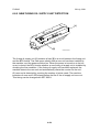
SERVICE MANUAL
July 30th, 2001
Subject to change
!IMPORTANT SAFETY NOTICES
PREVENTION OF PHYSICAL INJURY
1. Before disassembling or assembling parts of the printer and peripherals,
make sure that the printer power cord is unplugged.
2. The wall outlet should be near the printer and easily accessible.
3. If any adjustment or operation check has to be made with exterior covers off
or open while the main switch is turned on, keep hands away from electrified
or mechanically driven components.
4. The printer drives some of its components when it completes the warm-up
period. Be careful to keep hands away from the mechanical and electrical
components as the printer starts operation.
5. The inside and the metal parts of the fusing unit become extremely hot while
the printer is operating. Be careful to avoid touching those components with
your bare hands.
HEALTH SAFETY CONDITIONS
Toner and developer are non-toxic, but if you get either of them in your eyes by
accident, it may cause temporary eye discomfort. Try to remove with eye drops
or flush with water as first aid. If unsuccessful, get medical attention.
OBSERVANCE OF ELECTRICAL SAFETY STANDARDS
1. The printer and its peripherals must be serviced by a customer service
representative who has completed the training course on those models.
2. The NVRAM module (option) installed on the controller has a lithium battery
which can explode if replaced incorrectly. Replace the NVRAM only with an
identical one. The manufacturer recommends replacing the entire NVRAM.
Do not recharge or burn this battery. Used NVRAM must be handled in
accordance with local regulations.
3. The optional fax and memory expansion units contain lithium batteries,
which can explode if replaced incorrectly. Replace only with the same or an
equivalent type recommended by the manufacturer. Do not recharge or burn
the batteries. Used batteries must be handled in accordance with local
regulations.
SAFETY AND ECOLOGICAL NOTES FOR DISPOSAL
1. Do not incinerate toner bottles or used toner. Toner dust may ignite suddenly
when exposed to an open flame.
2. Dispose of used toner, the maintenance unit which includes developer or the
organic photoconductor in accordance with local regulations. (These are
non-toxic supplies.)
3. Dispose of replaced parts in accordance with local regulations.
When keeping used lithium batteries in order to dispose of them later, do not
put more than 100 batteries per sealed box. Storing larger numbers or not
sealing them apart may lead to chemical reactions and heat build-up.
4. When keeping used lithium batteries in order to dispose of them later, do not
put more than 100 batteries per sealed box. Storing larger numbers or not
sealing them apart may lead to chemical reactions and heat build-up.
LASER SAFETY
The Center for Devices and Radiological Health (CDRH) prohibits the repair of
laser-based optical units in the field. The optical housing unit can only be repaired
in a factory or at a location with the requisite equipment. The laser subsystem is
replaceable in the field by a qualified Customer Engineer. The laser chassis is not
repairable in the field. Customer engineers are therefore directed to return all
chassis and laser subsystems to the factory or service depot when replacement of
the optical subsystem is required.
!WARNING
Use of controls, or adjustment, or performance of procedures other than
those specified in this manual may result in hazardous radiation exposure.
!WARNING
WARNING: Turn off the main switch before attempting any of the
procedures in the Laser Optics Housing Unit section. Laser
beams can seriously damage your eyes.
CAUTION MARKING:
Trademarks
Microsoft®, Windows®, and MS-DOS® are registered trademarks of Microsoft
Corporation in the United States and /or other countries.
PostScript® is a registered trademark of Adobe Systems, Incorporated.
PCL® is a registered trademark of Hewlett-Packard Company.
Ethernet® is a registered trademark of Xerox Corporation.
PowerPC® is a registered trademark of International Business Machines
Corporation.
Other product names used herein are for identification purposes only and may be
trademarks of their respective companies. We disclaim any and all rights involved
with those marks.
TABLE OF CONTENTS
1 INSTALLATION ........................................................................... 1-1
1.1 INSTALLATION REQUIREMENTS ...........................................................1-1
1.1.1 ENVIRONMENT ...............................................................................1-1
1.1.2 MACHINE LEVEL .............................................................................1-1
1.1.3 MACHINE SPACE REQUIREMENT.................................................1-2
1.1.4 POWER REQUIREMENTS ..............................................................1-2
1.2 OPTIONAL UNIT COMBINATIONS ..........................................................1-3
1.3 INSTALLATION FLOW CHART ................................................................1-4
1.4 MACHINE INSTALLATION .......................................................................1-5
1.5 OPTIONAL UNIT INSTALLATION.............................................................1-7
1.5.1 LIST OF OPTIONS ...........................................................................1-7
Note for Transporting the Machine .......................................................1-7
1.5.2 PUNCH UNIT INSTALLATION .........................................................1-8
Accessory Check ..................................................................................1-8
Installation Procedure ...........................................................................1-9
2 PREVENTIVE MAINTENANCE.................................................... 2-1
2.1 USER MAINTENANCE .............................................................................2-1
2.2 SERVICE MAINTENANCE........................................................................2-3
3 REPLACEMENT AND ADJUSTMENT......................................... 3-1
3.1 SPECIAL TOOLS ......................................................................................3-1
3.2 IMAGE ADJUSTMENT..............................................................................3-2
3.2.1 REGISTRATION...............................................................................3-2
Image Area ...........................................................................................3-2
Leading Edge........................................................................................3-2
Side to Side ..........................................................................................3-2
Adjustment Standard ............................................................................3-2
Paper Registration Standard.................................................................3-2
1st side .................................................................................................3-2
2nd side in duplex.................................................................................3-2
Adjustment Procedure ..........................................................................3-3
3.2.2 COLOR REGISTRATION .................................................................3-3
Line Position Adjustment ......................................................................3-3
Adjustment for Line Speed of Fusing Unit.............................................3-3
3.2.3 PRINTER GAMMA ...........................................................................3-4
Adjustment Overview ............................................................................3-4
Adjustment Procedure ..........................................................................3-4
3.3 EXTERIOR COVERS ................................................................................3-5
3.3.1 REAR COVER AND UPPER REAR COVER ...................................3-5
3.3.2 PAPER EXIT TRAY ..........................................................................3-5
3.3.3 UPPER RIGHT COVER ...................................................................3-5
3.3.4 FRONT COVER ...............................................................................3-6
3.3.5 LEFT COVER AND REAR LEFT COVER ........................................3-6
3.3.6 UPPER LEFT COVER AND OPERATION PANEL ..........................3-7
i
3.4 LASER OPTICS ........................................................................................3-8
3.4.1 CAUTION DECAL LOCATIONS .......................................................3-8
3.4.2 LASER OPTICS HOUSING UNIT ....................................................3-9
Adjustments after Replacing the Laser Optics Housing Unit...............3-11
3.4.3 POLYGON MIRROR MOTOR ........................................................3-12
3.4.4 LASER SYNCHRONIZING DETECTOR BOARDS ........................3-12
3.5 PCU AND DEVELOPMENT UNIT ...........................................................3-13
3.6 PAPER FEED..........................................................................................3-14
3.6.1 PICK-UP, FEED, AND SEPARATION ROLLERS ..........................3-14
Tray 1 and Tray 2 ...............................................................................3-14
By-pass Tray.......................................................................................3-14
3.6.2 PAPER WIDTH DETECTION BOARD ...........................................3-15
3.6.3 VERTICAL TRANSPORT SENSOR ...............................................3-15
3.6.4 RIGHT DOOR UNIT .......................................................................3-16
3.6.5 REGISTRATION SENSOR AND RELAY SENSOR .......................3-17
3.6.6 PAPER FEED CLUTCHES.............................................................3-17
3.6.7 BY-PASS FEED CLUTCH ..............................................................3-18
3.6.8 TRAY LIFT MOTOR .......................................................................3-18
3.7 TRANSFER AND PAPER TRANSPORT UNIT .......................................3-19
3.7.1 TRANSFER UNIT ...........................................................................3-19
3.7.2 TRANSFER BELT CLEANING UNIT..............................................3-21
3.7.3 CLEANING BLADE AND CLEANING ROLLER .............................3-22
3.7.4 TRANSFER BELT ..........................................................................3-23
3.7.5 OTHERS.........................................................................................3-27
Front Plate ..........................................................................................3-27
Grounding Spring................................................................................3-27
Drive Gear and Left Drive Roller.........................................................3-27
3.8 FUSING ...................................................................................................3-28
3.8.1 FUSING UNIT.................................................................................3-28
3.8.2 OIL SUPPLY UNIT .........................................................................3-29
3.8.3 UPPER COVER .............................................................................3-29
3.8.4 FUSING BELT UNIT.......................................................................3-30
3.8.5 PRESSURE ROLLER.....................................................................3-33
3.8.6 PAPER EXIT ..................................................................................3-35
3.9 ELECTRICAL COMPONENTS................................................................3-36
3.9.1 MOVING THE CONTROLLER BOX OUT OF THE WAY ...............3-36
3.9.2 MOVING THE HIGH VOLTAGE SUPPLY UNIT C, B OUT OF THE WAY.................................................................3-36
3.9.3 CONTROLLER AND BCU ..............................................................3-37
3.9.4 NVRAM REPLACEMENT PROCEDURE .......................................3-38
NVRAM for BCU .................................................................................3-38
NVRAM for Controller .........................................................................3-38
NVRAMs for both BCU and Controller ................................................3-38
3.9.5 REMOVING THE HIGH VOLTAGE SUPPLY BOARD - C, B .........3-39
3.9.6 PSU ................................................................................................3-39
3.10 DRIVE UNIT ..........................................................................................3-40
3.10.1 REGISTRATION CLUTCH ...........................................................3-40
DEVELOPMENT CLUTCHES ............................................................3-41
3.10.3 DEVELOPMENT DRIVE MOTOR - CMY .....................................3-42
ii
3.10.4 DRUM DRIVE MOTOR - CMY AND
DRUM DRIVE MOTOR - K...........................................................3-43
DEVELOPMENT DRIVE MOTOR - K .................................................3-44
4 TROUBLESHOOTING ................................................................. 4-1
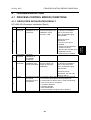
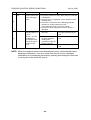
4.1 PROCESS CONTROL ERROR CONDITIONS .........................................4-1
4.1.1 DEVELOPER INITIALIZATION RESULT .........................................4-1
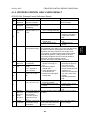
4.1.2 PROCESS CONTROL SELF-CHECK RESULT ...............................4-3
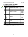
4.1.3 LINE POSITION ADJUSTMENT RESULT .......................................4-4
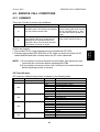
4.2 SERVICE CALL CONDITIONS .................................................................4-7
4.2.1 SUMMARY .......................................................................................4-7
SC Classification...................................................................................4-7
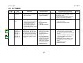
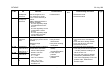
4.3 SC TABLE .................................................................................................4-9
4.4 TROUBLESHOOTING GUIDE ................................................................4-33
4.4.1 IMAGE QUALITY............................................................................4-33
4.4.2 COLOR SHIFT ...............................................................................4-37
Adjustment Standard: Max. 200 µm...................................................4-39
Preparation .........................................................................................4-39
How to measure the gap between color lines .....................................4-44
4.4.3 COLOR SHIFT AFTER TRANSFER UNIT REPLACEMENT .........4-46
Check the color shift level ...................................................................4-46
Fusing/ Registration Roller Speed Adjustment ...................................4-46
SP mode (sub-scan registration) reset................................................4-46
Transfer belt aging ..............................................................................4-46
Fusing roller speed adjustment...........................................................4-47
Registration roller speed adjustment (for color mode) ........................4-47
Line position fine adjustment for sub-scan..........................................4-47
Registration roller speed adjustment (For B&W mode).......................4-48
4.5 ELECTRICAL COMPONENT DEFECTS ................................................4-49
4.5.1 SENSORS ......................................................................................4-49
4.6 BLOWN FUSE CONDITIONS .................................................................4-50
4.7 LEDS (BCU) ............................................................................................4-50
5 SERVICE TABLES....................................................................... 5-1
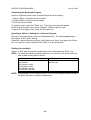
5.1 SERVICE PROGRAM MODE....................................................................5-1
5.1.1 ENABLING AND DISABLING SERVICE PROGRAM MODE ...........5-1
Entering the Service Mode....................................................................5-1
Accessing the Required Program .........................................................5-2
Inputting a Value or Setting for a Service Program ...............................5-2
Exiting Service Mode ............................................................................5-2
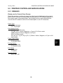
5.2 PRINTER CONTROLLER SERVICE MODE .............................................5-3
5.2.1 REMARKS........................................................................................5-3
Display on the Control Panel Screen ....................................................5-3
Others ...................................................................................................5-4
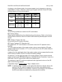
5.2.2 SERVICE MODE MENU (“1. SERVICE”) .........................................5-5
5.2.3 BIT SWITCH PROGRAMMING ........................................................5-6
5.3 PRINTER ENGINE SERVICE MODE........................................................5-7
5.3.1 SERVICE MODE TABLE (“2. ENGINE”) ..........................................5-7
SP1-XXX (Feed) ...................................................................................5-7
iii
SP2-XXX (Drum).................................................................................5-13
SP3-XXX (Process) ............................................................................5-23
SP5-XXX (Mode) ................................................................................5-30
SP6-XXX (Peripherals) .......................................................................5-38
SP7-XXX (Data Log)...........................................................................5-39
5.3.2 INPUT CHECK TABLE ...................................................................5-47
Table 1: Paper Height Sensor.............................................................5-49
Table 2: Paper Size Switch (Tray 2) ...................................................5-49
Table 3: Paper Size (By-pass Table) ..................................................5-49
5.3.3 OUTPUT CHECK TABLE ...............................................................5-50
5.3.4 TEST PATTERN (SP5-997) ...........................................................5-54
5.4 FIRMWARE UPDATE PROCEDURE......................................................5-55
5.4.1 TYPE OF FIRMWARE....................................................................5-55
5.4.2 ERROR RECOVERY......................................................................5-55
Engine Firmware/Controller NIB Firmware .........................................5-55
Controller System Firmware: ..............................................................5-55
5.4.3 CONTROLLER/ENGINE FIRMWARE UPGRADE .........................5-56
5.5 CONTROLLER SELF-DIAGNOSTICS ....................................................5-57
5.5.1 OVERVIEW ....................................................................................5-57
5.5.2 DETAILED SELF-DIAGNOSTICS ..................................................5-58
5.6 USER PROGRAM MODE .......................................................................5-59
5.7 DIP SWITCHES.......................................................................................5-60
Controller Board..................................................................................5-60
6 DETAILED SECTION DESCRIPTIONS ....................................... 6-1
6.1 OVERVIEW ...............................................................................................6-1
6.1.1 COMPONENT LAYOUT ...................................................................6-1
6.1.2 PAPER PATH...................................................................................6-2
6.1.3 DRIVE LAYOUT ...............................................................................6-3
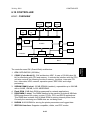
6.1.4 BOARD STRUCTURE......................................................................6-4
Overview...............................................................................................6-4
Descriptions ..........................................................................................6-5
6.1.5 PRINTING PROCESS ......................................................................6-6
6.2 PROCESS CONTROL ..............................................................................6-8
6.2.1 OVERVIEW ......................................................................................6-8
6.2.2 POTENTIAL CONTROL ...................................................................6-8
Overview...............................................................................................6-8
Process Control Self Check ..................................................................6-9
6.2.3 PROCESS CONTROL SELF CHECK PROCEDURE ....................6-10
Step 1: VSG Adjustment......................................................................6-10
Step 2: ID Sensor Solid Pattern Generation .......................................6-11
Step 3: Sensor Pattern Detection .......................................................6-11
Step 4: Toner Amount Calculation ......................................................6-11
Step 5: VD, VB, VL Selection and VREF Adjustment............................6-11
Step 6: ID Sensor Highlight Pattern Generation .................................6-12
Step 7: Sensor Pattern Density Detection...........................................6-12
Step 8: VL (LD Power) Selection.........................................................6-13
6.2.4 TONER SUPPLY CONTROL .........................................................6-14
Overview.............................................................................................6-14
iv
Toner Supply Control Modes ..............................................................6-14
6.2.5 TONER NEAR END/TONER END DETECTION............................6-15
Introduction .........................................................................................6-15
Toner Near End Detection ..................................................................6-15
Toner End Detection ...........................................................................6-15
Toner End Recovery ...........................................................................6-15
6.2.6 DEVELOPER INITIALIZATION ......................................................6-16
6.3 LASER EXPOSURE................................................................................6-17
6.3.1 OVERVIEW ....................................................................................6-17
6.3.2 OPTICAL PATH..............................................................................6-18
6.3.3 LASER SYNCHRONIZING DETECTOR ........................................6-19
Overview.............................................................................................6-19
Main Scan Start Detection ..................................................................6-19
Clock Frequency Adjustment ..............................................................6-19
6.3.4 DUAL BEAM WRITING ..................................................................6-20
Dual Beam Mechanism.......................................................................6-20
Laser Beam Pitch Change Mechanism...............................................6-20
6.3.5 LD SAFETY SWITCH .....................................................................6-21
6.3.6 AUTOMATIC LINE POSITION ADJUSTMENTS ............................6-22
Overview.............................................................................................6-22
Sub Scan Line Position for YCM.........................................................6-23
Main Scan Line Position for KYCM .....................................................6-23
Magnification Adjustment....................................................................6-23
Main Scan Skew Adjustment ..............................................................6-24
6.4 PHOTOCONDUCTOR UNIT ...................................................................6-25
6.4.1 OVERVIEW ....................................................................................6-25
6.4.2 DRIVE.............................................................................................6-26
6.4.3 DRUM CHARGE AND QUENCHING .............................................6-27
6.4.4 DRUM CLEANING..........................................................................6-28
6.4.5 WASTE TONER COLLECTION .....................................................6-29
6.4.6 WASTE TONER BOTTLE FULL DETECTION ...............................6-30
6.4.7 PCU DETECTION (DEVELOPMENT UNIT DETECTION) .............6-31
6.5 DEVELOPMENT .....................................................................................6-32
6.5.1 OVERVIEW ....................................................................................6-32
6.5.2 DRIVE.............................................................................................6-33
6.5.3 DEVELOPER AGITATION .............................................................6-34
6.5.4 DEVELOPMENT BIAS ...................................................................6-35
6.5.5 DEVELOPMENT UNIT DETECTION..............................................6-35
6.5.6 TONER SUPPLY MECHANISM .....................................................6-36
Overview.............................................................................................6-36
Toner Agitation ...................................................................................6-36
Toner Transport ..................................................................................6-37
6.5.7 TONER CARTRIDGE DETECTION ...............................................6-38
6.6 PAPER FEED..........................................................................................6-39
6.6.1 OVERVIEW ....................................................................................6-39
6.6.2 DRIVE – TRAYS 1 AND 2 ..............................................................6-40
6.6.3 PAPER LIFT – TRAYS 1 & 2..........................................................6-41
6.6.4 PAPER SIZE DETECTION – TRAYS 1 & 2....................................6-42
6.6.5 PAPER HEIGHT DETECTION – TRAYS 1 & 2 ..............................6-43
v
6.6.6 PAPER END DETECTION – TRAYS 1 & 2 ....................................6-43
6.6.7 REGISTRATION.............................................................................6-44
6.6.8 PAPER FEED LINE SPEED...........................................................6-45
6.6.9 BY-PASS TRAY..............................................................................6-46
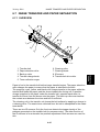
6.7 IMAGE TRANSFER AND PAPER SEPARATION ...................................6-47
6.7.1 OVERVIEW ....................................................................................6-47
6.7.2 TRANSFER BELT DRIVE ..............................................................6-48
6.7.3 TRANSFER AND CLEANING CURRENT ......................................6-49
6.7.4 TRANSFER BELT CLEANING .......................................................6-50
6.7.5 TRANSFER BELT CONTACT ........................................................6-51
Mechanism .........................................................................................6-51
ACS (Auto Color Sensing) Mode ........................................................6-52
6.8 FUSING ...................................................................................................6-53
6.8.1 OVERVIEW ....................................................................................6-53
6.8.2 FUSING UNIT DRIVE.....................................................................6-54
6.8.3 FUSING TEMPERATURE CONTROL............................................6-55
Fusing Temperatures..........................................................................6-55
Temperature Corrections ....................................................................6-56
Overheat Protection ............................................................................6-56
6.8.4 OIL SUPPLY AND CLEANING.......................................................6-57
6.8.5 NEW FUSING OIL SUPPLY UNIT DETECTION............................6-58
6.8.6 NEW FUSING UNIT DETECTION..................................................6-59
6.8.7 ENERGY SAVER MODE................................................................6-60
Level 1 Energy Saver Mode................................................................6-60
Level 2 Energy Saver Mode................................................................6-60
6.9 PAPER EXIT ...........................................................................................6-61
6.9.1 OVERVIEW ....................................................................................6-61
6.9.2 PAPER OVERFLOW DETECTION ................................................6-62
6.10 CONTROLLER ......................................................................................6-63
6.10.1 OVERVIEW ..................................................................................6-63
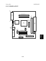
6.10.2 BOARD LAYOUT..........................................................................6-65
6.10.3 PRINT DATA PROCESSING .......................................................6-66
RPCS Driver .......................................................................................6-66
PCL5c Driver ......................................................................................6-66
PS3 Driver ..........................................................................................6-67
CMS (Color Management System) .....................................................6-67
Gray Correction ..................................................................................6-67
BG/UCR (Black Generation/Under Color Removal)............................6-67
Gamma Correction .............................................................................6-67
Toner Limitation ..................................................................................6-68
Dither Processing and ROP/RIP.........................................................6-68
6.10.4 CONTROLLER FUNCTIONS .......................................................6-69
Sample Print .......................................................................................6-69
Locked Print........................................................................................6-69
Paper Source Selection ......................................................................6-70
Tray Priority (Auto Tray Select)...........................................................6-70
Tray Lock ............................................................................................6-70
Manual Tray Select .............................................................................6-70
Auto Continue .....................................................................................6-71
vi
Overview.............................................................................................6-71
Auto Tray Select .................................................................................6-71
Manual Tray Select .............................................................................6-71
Paper Output Tray ..............................................................................6-72
Output Tray Selected ..........................................................................6-72
Sequential Stacking ............................................................................6-72
Stapling...............................................................................................6-73
Punching.............................................................................................6-73
6.11 IEEE1394 INTERFACE .........................................................................6-74
6.11.1 SPECIFICATIONS........................................................................6-74
Hardware Specification .......................................................................6-74
System Requirements.........................................................................6-74
6.11.2 IEEE1394 .....................................................................................6-74
6.11.3 BLOCK DIAGRAM........................................................................6-75
6.11.4 PIN ASSIGNMENT .......................................................................6-75
6.11.5 REMARKS ABOUT THIS INTERFACE KIT..................................6-76
6.11.6 TROUBLESHOOTING NOTES ....................................................6-76
PERIPHERALS
DUPLEX UNIT (Machine Code: G571)
1 REPLACEMENT AND ADJUSTMENT...................................G571-1
1.1 DUPLEX INVERTER UNIT................................................................. G571-1
1.1.1 TOP COVER ............................................................................. G571-1
1.1.2 DUPLEX CONTROL BOARD .................................................... G571-1
1.1.3 DUPLEX INVERTER MOTOR 1 ................................................ G571-2
1.1.4 DUPLEX INVERTER MOTOR 2 AND SWITCH ........................ G571-2
1.1.5 EXIT SENSOR 3 AND DUPLEX INVERTER SENSOR............. G571-3
1.1.6 EXIT SENSOR 1 AND 2 ............................................................ G571-3
1.2 DUPLEX FEED UNIT ......................................................................... G571-4
1.2.1 DUPLEX DRIVE BOARD........................................................... G571-4
1.2.2 DUPLEX FEED MOTOR ........................................................... G571-4
1.2.3 DUPLEX FEED SENSOR.......................................................... G571-5
2 DETAILED DESCRIPTIONS ..................................................G571-6
2.1 OVERVIEW ........................................................................................ G571-6
2.2 DUPLEX OPERATION ....................................................................... G571-7
2.2.1 UP TO A4/LT(81/2" X 11") LEF .................................................. G571-7
2.2.2 LARGER THAN A4/LT(81/2" X 11") LEF.................................... G571-7
2.3 DUPLEX INVERTER UNIT................................................................. G571-8
2.3.1 DRIVE........................................................................................ G571-8
2.3.2 FEED TO EXTERNAL EXIT TRAY (NON-DUPLEX MODE) ..... G571-9
2.3.3 FEED TO DUPLEX FEED UNIT .............................................. G571-10
2.3.4 FEED TO TWO-TRAY FINISHER ........................................... G571-11
With Optional One-Tray Paper Feed Unit .................................... G571-11
vii
With Optional LCT or Two-Tray Paper Feed Unit ........................ G571-11
2.4 DUPLEX FEED UNIT ....................................................................... G571-12
2.4.1 DRIVE...................................................................................... G571-12
2.4.2 FEED-IN AND FEED-OUT ...................................................... G571-12
ONE-TRAY PAPER FEED UNIT (Machine Code: G567)
1 REPLACEMENT AND ADJUSTMENT...................................G567-1
1.1 COVER REPLACEMENT ................................................................... G567-1
1.2 ROLLER REPLACEMENT ................................................................. G567-2
1.2.1 PAPER FEED, SEPARATION, AND PICK-UP ROLLERS ........ G567-2
1.3 PAPER FEED MOTOR AND MAIN BOARD ...................................... G567-3
1.4 TRAY LIFT MOTOR ........................................................................... G567-4
1.5 PAPER FEED CLUTCH ..................................................................... G567-4
1.6 PAPER FEED UNIT REPLACEMENT................................................ G567-5
2 DETAILED DESCRIPTIONS ..................................................G567-6
2.1 OVERVIEW ........................................................................................ G567-6
2.1.1 MECHANICAL COMPONENT LAYOUT.................................... G567-6
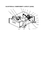
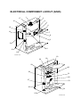
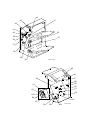
2.1.2 ELECTRICAL COMPONENT LAYOUT ..................................... G567-7
2.1.3 DRIVE LAYOUT ........................................................................ G567-8
TWO-TRAY PAPER FEED UNIT (Machine Code: G568)
1 REPLACEMENT AND ADJUSTMENT...................................G568-1
1.1 COVER REPLACEMENT ................................................................... G568-1
1.2 ROLLER REPLACEMENT ................................................................. G568-2
1.2.1 PAPER FEED, SEPARATION, AND PICK-UP ROLLERS ........ G568-2
1.3 PAPER FEED MOTOR AND MAIN BOARD ...................................... G568-3
1.4 TRAY LIFT MOTORS......................................................................... G568-4
1.5 PAPER FEED CLUTCHES ................................................................ G568-4
1.6 PAPER FEED UNIT REPLACEMENT................................................ G568-5
2 DETAILED DESCRIPTIONS ..................................................G568-6
2.1 OVERVIEW ........................................................................................ G568-6
2.1.1 MECHANICAL COMPONENT LAYOUT.................................... G568-6
2.1.2 ELECTRICAL COMPONENT LAYOUT ..................................... G568-7
2.1.3 DRIVE LAYOUT ........................................................................ G568-8
LARGE CAPACITY TRAY (Machine Code: G569)
1 REPLACEMENT AND ADJUSTMENT...................................G569-1
71.1 DETACHING THE TRAY FROM THE MAINFRAME........................ G569-1
1.2 REAR FENCE HP SENSOR .............................................................. G569-1
viii
1.3
1.4
1.5
1.6
1.7
1.8
1.9
CHANGING THE TRAY PAPER SIZE ............................................... G569-2
LEFT TRAY PAPER END SENSOR .................................................. G569-3
TRAY LIFT MOTOR ........................................................................... G569-4
TRAY MOTOR AND STACK TRANSPORT CLUTCH........................ G569-5
PAPER FEED CLUTCH ..................................................................... G569-6
PAPER FEED UNIT ........................................................................... G569-7
UPPER LIMIT, RIGHT TRAY PAPER END,
AND RELAY SENSORS..................................................................... G569-8
1.10 PICK-UP/PAPER FEED/SEPARATION ROLLER ............................ G569-9
2 DETAILED SECTION DESCRIPTIONS ...............................G569-10
2.1 OVERVIEW ...................................................................................... G569-10
2.1.1 MECHANICAL COMPONENT LAYOUT.................................. G569-10
2.1.2 ELECTRICAL COMPONENT LAYOUT ................................... G569-11
2.2 PAPER FEED................................................................................... G569-12
2.3 SEPARATION ROLLER AND PICK-UP ROLLER RELEASE .......... G569-13
2.4 TRAY LIFT ....................................................................................... G569-14
2.5 NEAR END/END DETECTION......................................................... G569-15
2.6 PAPER STACK TRANSPORT MECHANISM................................... G569-16
2.7 RIGHT TRAY PAPER END DETECTION ........................................ G569-17
TWO-TRAY FINISHER (Machine Code: G565)
1 REPLACEMENT AND ADJUSTMENT...................................G565-1
1.1 COVERS ............................................................................................ G565-1
1.1.1 EXTERNAL COVERS................................................................ G565-1
1.1.2 INNER COVER.......................................................................... G565-1
1.2 POSITIONING ROLLER..................................................................... G565-2
1.3 TRAY 1 EXIT SENSOR...................................................................... G565-2
1.4 ENTRANCE SENSOR/STAPLER TRAY ENTRANCE SENSOR ....... G565-3
1.5 STAPLER TRAY................................................................................. G565-3
1.6 UPPER STACK HEIGHT SENSORS/
TRAY 1 UPPER LIMIT SWITCH ........................................................ G565-4
1.7 EXIT GUIDE PLATE MOTOR............................................................. G565-5
1.8 LIFT MOTORS ................................................................................... G565-5
1.9 LOWER EXIT SENSOR ..................................................................... G565-7
1.10 LOWER STACK HEIGHT SENSORS .............................................. G565-8
1.11 TRAY 2 SHUNT POSITION SENSOR ............................................. G565-8
1.12 STAPLER UNIT................................................................................ G565-9
1.13 STAPLER ROTATION HP SENSOR................................................ G565-9
1.14 TRAY 1 INTERIOR......................................................................... G565-10
1.14.1 TRAY 1 COVERS .................................................................. G565-10
tray Shift Sensors and tray release sensor .................................. G565-11
1.14.3 TRAY 1 SHIFT MOTOR ........................................................ G565-11
1.14.4 BACK FENCE LOCK CLUTCH ............................................. G565-11
1.15 FINISHER MAIN BOARD ............................................................... G565-12
1.16 PUNCH HOLE POSITION ADJUSTMENT ..................................... G565-12
ix
2 TROUBLESHOOTING .........................................................G565-13
2.1 JAM DETECTION............................................................................. G565-13
3 SERVICE TABLES...............................................................G565-14
3.1 DIP SWITCH SETTINGS ................................................................. G565-14
3.2 TEST POINTS .................................................................................. G565-14
3.3 FUSES ............................................................................................. G565-14
4 DETAILED DESCRIPTIONS ................................................G565-15
4.1
4.2
4.3
4.4
GENERAL LAYOUT ......................................................................... G565-15
DRIVE LAYOUT ............................................................................... G565-16
JUNCTION GATES .......................................................................... G565-17
TRAY SHIFTING .............................................................................. G565-18
4.4.1 TRAY SHIFT MECHANISMS .................................................. G565-18
Tray 1 (Upper Tray) ..................................................................... G565-18
Tray 2 (Lower Tray) ..................................................................... G565-19
4.5 TRAY UP/DOWN MECHANISMS .................................................... G565-20
4.5.1 TRAY 1 .................................................................................... G565-20
Introduction .................................................................................. G565-20
Normal and sort/stack modes ...................................................... G565-20
Staple Mode................................................................................. G565-21
Tray 1 release mechanism........................................................... G565-22
4.5.2 TRAY 2 .................................................................................... G565-23
4.5.3 PRE-STACK MECHANISM ..................................................... G565-24
4.6 JOGGER UNIT PAPER POSITIONING MECHANISM..................... G565-25
Vertical Paper Alignment ............................................................. G565-25
Horizontal Paper Alignment ......................................................... G565-25
4.7 STAPLER MECHANISM .................................................................. G565-26
4.7.1 STAPLER MOVEMENT........................................................... G565-26
Stapler Rotation ........................................................................... G565-26
Side-to-Side Movement ............................................................... G565-26
4.7.2 STAPLER ................................................................................ G565-27
4.7.3 FEED OUT AND TRANSPORT ............................................... G565-28
4.8 PUNCH UNIT (OPTIONAL) .............................................................. G565-29
4.8.1 PUNCH DRIVE MECHANISM ................................................. G565-29
4.8.2 PUNCH WASTE COLLECTION .............................................. G565-30
FOUR-BIN MAILBOX (Machine Code: G566)
1 REPLACEMENT AND ADJUSTMENT...................................G566-1
1.1 EXTERIOR COVER REMOVAL ......................................................... G566-1
1.2 TRAY PAPER/OVERFLOW/VERTICAL TRANSPORT SENSORS ... G566-2
1.3 MAIN MOTOR REPLACEMENT ........................................................ G566-3
2 DETAILED DESCRIPTIONS ..................................................G566-4
2.1 COMPONENT LAYOUT..................................................................... G566-4
2.1.1 MECHANICAL COMPONENT LAYOUT.................................... G566-4
x
2.1.2 DRIVE LAYOUT ........................................................................ G566-4
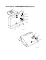
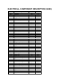
2.2 ELECTRICAL COMPONENT DESCRIPTIONS ................................. G566-5
2.3 BASIC OPERATION........................................................................... G566-6
2.4 PAPER OVERFLOW DETECTION .................................................... G566-7
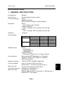
SPECIFICATIONS.....................................................................SPEC-1
1 GENERAL SPECIFICATIONS.............................................................. SPEC-1
1.1 SUPPORTED PAPER SIZES...................................................... SPEC-3
1.1.1 PAPER FEED........................................................................... SPEC-3
1.1.2 PAPER EXIT ............................................................................ SPEC-4
2 SOFTWARE ACCESSORIES .............................................................. SPEC-5
2.1 PRINTER DRIVERS .................................................................... SPEC-5
2.2 UTILITY SOFTWARE .................................................................. SPEC-5
3 MACHINE CONFIGURATION .............................................................. SPEC-6
4 OPTIONAL EQUIPMENT ..................................................................... SPEC-8
4.1 500-SHEET TRAY ....................................................................... SPEC-8
4.2 1000-SHEET TRAY ..................................................................... SPEC-8
4.3 2000-SHEET LARGE CAPACITY TRAY ..................................... SPEC-8
4.4 TWO-TRAY FINISHER & PUNCH UNIT ..................................... SPEC-9
4.5 FOUR-BIN MAILBOX ................................................................ SPEC-10
xi
INSTALLATION REQUIREMENTS
1. INSTALLATION
1.1 INSTALLATION REQUIREMENTS
1.1.1 ENVIRONMENT
1. Temperature Range:
10°C to 32°C (50°F to 89.6°F)
2. Humidity Range:
15% to 80% RH
3. Ambient Illumination:
Less than 2,000 lux (do not expose to direct sunlight)
4. Ventilation:
3 times/hr/person or more
5. Avoid exposing the machine to sudden temperature changes, which include:
1) Direct cool air from an air conditioner
2) Direct heat from a heater
6. Avoid installing the machine in areas that might be exposed to corrosive gas.
7. Install the machine at a location lower than 2,500 m (8,200 ft.) above sea level.
8. Install the machine on a strong, level base. (Inclination on any side must be no
more than 5 mm.)
9. Avoid installing the machine in areas that may be subjected to strong vibration.
1.1.2 MACHINE LEVEL
Front to back:
Within 5 mm (0.2")
Right to left:
Within 5 mm (0.2")
1-1
Installation
30 July, 2001
INSTALLATION REQUIREMENTS
30 July, 2001
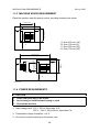
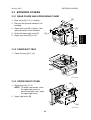
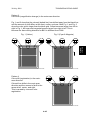
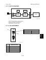
1.1.3 MACHINE SPACE REQUIREMENT
Place the machine near the power source, providing clearance as shown.
575mm (23")
B
678mm (27")
C
A
A: Over 460 mm (18")
B: Over 100 mm (4")
C: Over 550 mm (22")
D: Over 700 mm (28")
D
G060I801.WMF
1450mm (57")
B
678mm
(27")
C
A
D
G060I802.WMF
1.1.4 POWER REQUIREMENTS
!CAUTION
1. Insert firmly the plug in the outlet.
2. Avoid using an outlet extension plug or cord.
3. Ground the machine.
1. Input voltage level: 120 V, 60 Hz: More than 10 A
220 V ~ 240 V, 50 Hz/60 Hz: More than 6 A
2. Permissible voltage fluctuation: ±10 %
3. Do not put or place anything on the power cord.
1-2
OPTIONAL UNIT COMBINATIONS
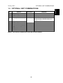
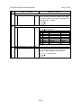
1.2 OPTIONAL UNIT COMBINATIONS
Item
No.
1
2
3
4
5
6
7
8
9
10
11
Options
PFU (1 Tray)
PFU (2 Trays)
LCT
Two-tray finisher
3 types of punch kit
Four-bin mailbox
Duplex unit
3 types of memory DIMM
HDD
IEEE 1394
NVRAM
Alternative
Items 2, 3
Items 1, 3
Items 1, 2
Item 6
Required
• Item 7
• Item 8 (Total 128 MB needed) or 9
• Item 1, 2 or 3
Item 4
Items 4, 5
Item 8
NOTE: Two memory DIMMs (up to 384 MB) can be installed.
1-3
Installation
30 July, 2001
INSTALLATION FLOW CHART
30 July, 2001
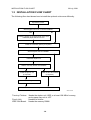
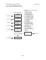
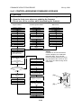
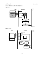
1.3 INSTALLATION FLOW CHART
The following flow chart shows how to install the optional units more efficiently.
Unpack the printer.
Will the paper feed unit or LCT be installed?
Yes
No
Place the printer on the paper feed unit or LCT.
Install the paper feed unit or LCT.
Install the controller options (if required).
Will the duplex unit be installed?
Yes
No
Install the duplex unit.
Will the Two-tray finisher be installed?
Yes
No
Install the punch unit
(if required).
Install the four-bin mailbox
(if required).
Install the two-tray finisher.
Install the printer.
G060I002.WMF
Two-tray Finisher:
Punch Unit:
IEEE1394 Board:
Needs the duplex unit, HDD or at least 128 MB of memory,
and a paper tray unit or LCT.
Needs the finisher.
Needs the memory DIMM.
1-4
MACHINE INSTALLATION
1.4 MACHINE INSTALLATION
Refer to the Operating Instructions for details.
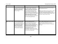
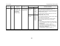
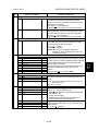
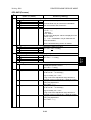
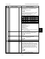
If the customer has a service contract, change the settings of the following SP
modes depending on the contract type.
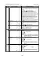
Item
Meter charge
SP No.
SP5-930-1
Counting method
SP5-045-1
A3/11" x 17"
double counting
PM warning
display 1
SP5-104-1
PM warning
display 2
SP5-930-4
to
SP5-930-5
SP5-812-2
Fax No. setting
SP5-930-3
Function
Specifies whether the meter charge
mode is enabled or disabled.
Meter charge mode enabled:
• The Counter menu appears
immediately after the Menu key is
pressed.
• The counter type selected by the
counting method (SP5-045-1) can be
displayed with the Counter menu.
• The counter values can also be
printed with the Counter menu.
• The selected counter starts from a
negative number.
Meter charge mode disabled:
• The Counter menu is not displayed.
• The total counter starts from 0.
Specifies whether the counting
method used in meter charge mode is
based on developments or prints.
Important:
This SP can only be done before the
negative counters are reset with SP7825-001
Specifies whether the counter is
doubled for A3/11" x 17" paper.
Specifies whether the PM warning for
PCUs and development units is
displayed when the replacement time
arrives.
Type 1: Displayed
Type 2: Not displayed
Specifies whether the PM warning for
the paper feed roller and transfer unit
is displayed.
Programs the service station fax
number.
The number is printed on the counter
list when the meter charge mode is
selected, so that the user can fax the
counter data to the service station.
1-5
Default
Off
Developments
No: Single
counting
Type 1
Off:
Installation
30 July, 2001
MACHINE INSTALLATION
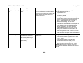
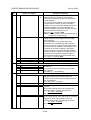
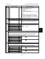
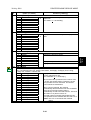
Item
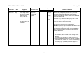
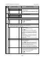
Counter reset
SP No.
SP7-825-1
30 July, 2001
Function
Resets the counters to 0.
Important: This must be done at
installation after all the above settings
have been finished. The negative
counters used in meter charge mode
will be reset to zero.
Default
NOTE: 1) The default setting for this machine is meter-charge mode off.
2) The meter-charge counter cannot be reset.
1-6
OPTIONAL UNIT INSTALLATION
1.5 OPTIONAL UNIT INSTALLATION
1.5.1 LIST OF OPTIONS
The available options are listed below. Except for the punch unit, installation is
explained in the Operating Instructions.
• Paper Feed Unit (500 sheets x 1)
• Paper Feed Unit (500 sheets x 2)
• Large Capacity Tray
• Two-tray Finisher
• Punch Unit
• Four-bin Mailbox
• DIMM Memory (64/128/256 MB)
• IEEE1394 Board
• HDD
• NVRAM
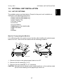
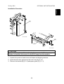
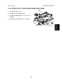
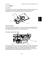
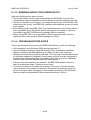
Note for Transporting the Machine
If it is difficult to slide the machine across the floor after installing the optional paper
feed unit or LCT, remove the two stands with the following procedure.
[A]
G571R112.WMF
G568I901.WMF
[B]
1. Remove all trays in the optional paper feed unit or LCT.
2. Remove the front stand [A] (! x 2).
3. Remove the rear stand [B] (! x 2, 2 brackets).
CAUTION: Reinstall the two stands in their original positions, or the machine might
tip over when drawing out the paper trays and so on.
1-7
Installation
30 July, 2001
OPTIONAL UNIT INSTALLATION
30 July, 2001
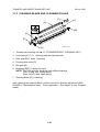
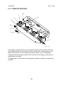
1.5.2 PUNCH UNIT INSTALLATION
Accessory Check
Check the quantity and condition of the accessories in the box against the following
list:
Description
Q’ty
1. Punch unit ..................................................................................1
2. Sensor arm ................................................................................1
3. Hopper .......................................................................................1
4. Step screw .................................................................................1
5. Spring.........................................................................................1
6. Spacer (2 mm) ...........................................................................1
7. Spacer (1 mm) ...........................................................................1
8. Tapping screw............................................................................1
9. Tapping screw............................................................................2
1-8
30 July, 2001
OPTIONAL UNIT INSTALLATION
Installation
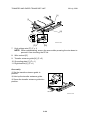
Installation Procedure
[A]
B377I102.WMF
[B]
[C]
B377I103.WMF
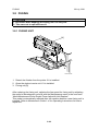
!CAUTION
Switch off the main machine and unplug its power cord. If the two-tray
finisher is installed, disconnect it and pull it away from the machine.
1. Unpack the punch unit and remove all tapes and shipping retainers.
2. Open the front door and remove the rear cover [A] (! x 4).
3. Remove the bracket [B] (! x 2) and paper guide [C] (! x 1).
1-9
OPTIONAL UNIT INSTALLATION
30 July, 2001
[B]
[A]
[C]
B377I101.WMF
[E]
B377I104.WMF
[D]
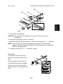
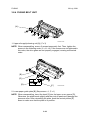
4. Remove the hopper cover [A] (! x 2).
5. Install the sensor bracket [B] (stepped ! x 1).
6. Install the spring [C].
7. Install the 2 mm spacer [D].
8. Install the punch unit [E] (! x 2, stepped ! x 1).
1-10
OPTIONAL UNIT INSTALLATION
Installation
30 July, 2001
[A]
B377I200.WMF
[C]
[B]
B377I106.WMF
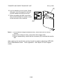
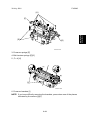
9. Connect the harnesses [A] and clamp them as shown.
10. Slide in the hopper [B].
11. Fasten the two 1 mm spacers [C] to the rear frame for future adjustment.
NOTE: The spacers are used to adjust the horizontal positioning of the punch
holes.
12. Reassemble the finisher and check the punch operation.
1-11
30 July, 2001
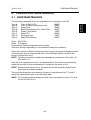
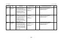
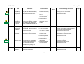
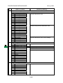
USER MAINTENANCE
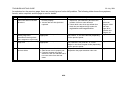
2. PREVENTIVE MAINTENANCE
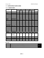
2.1 USER MAINTENANCE
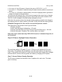
Type A
Type B
Type C
Type D
Type E
Type F
Type G
Type H
Color (C/M/Y) PCU
Color (C/M/Y) Development Unit
Fusing Unit
Black Development Unit / Dust Filter
Waste Toner Bottle
Black PCU
Oil Supply Unit
Paper Feed Rollers
100KP
100KP
100KP
100KP
50KP
100KP
20KP
150KP
Chart: A4(LT)/5%
Mode: 5 prints/job
Environment: Normal temperature and humidity
Yield may change depending on circumstances and print conditions.
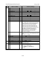
When the machine’s default settings are used, an error message is displayed when
a maintenance counter reaches the value in the PM table below, except for the
items in maintenance kit H.
NOTE: To have the machine display the message for maintenance kit H also, set
SP5-930-4 to 1.
After the user replaces the items in a maintenance kit, the machine automatically
resets the counter for this maintenance kit, except for the items in kit H.
NOTE: Except for the items in kit H, the machine can automatically detect when
new items have been installed.
The machine stops when the counters for parts in maintenance kits C, E and G
reach the replacement value in the following table.
NOTE: To have the machine display the alert only for maintenance kits C, E, and
G, set SP5-930-3 to 0.
2-1
Preventive
Maintenance
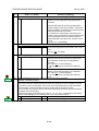
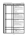
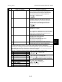
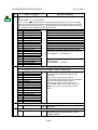
The following maintenance kits are available for the customer to do PM.
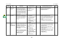
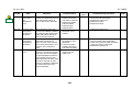
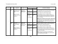
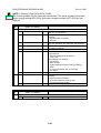
USER MAINTENANCE
Symbol key:
30 July, 2001
C: Clean, R: Replace, L: Lubricate, I: Inspect
Main Unit
Item
20K
50K
100K
Black PCU
150K
EM
Remarks
Included in maintenance
kit F
Included in maintenance
kit A
Included in maintenance
kit D
Included in maintenance
kit B
Included in maintenance
kit C
Included in maintenance
kit G
Included in maintenance
kit E
Included in maintenance
kit D
Included in maintenance
kit H
Included in maintenance
kit H
Included in maintenance
kit H
EM
Remarks
Discard chads.
R
Color (Y/M/C) PCU
R
Black Development Unit
R
Color (C/M/Y) Development Unit
R
Fusing Unit
R
Oil Supply Unit
R
Waste Toner Bottle
R
Dust Filter
R
Pick-up Roller
R
Feed Roller
R
Separation Roller
R
Punch Kit
Item
Chads
10K
I
2-2
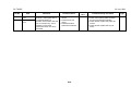
30 July, 2001
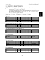
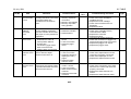
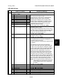
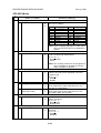
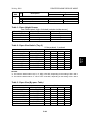
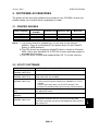
SERVICE MAINTENANCE
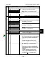
NOTE: After replacing the transfer unit, make sure to reset the maintenance
counter using SP7-804-16 and 7-804-27.
After replacing paper feed rollers, reset the maintenance counters for these
also: By-pass tray (7-804-10), Tray 1 (7-804-11), Tray 2 (7-804-12), Tray
3/LCT (7-804-13), Tray 4 (7-804-14)
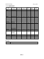
Symbol key:
C: Clean, R: Replace, L: Lubricate, I: Inspect
Main unit
Item
Transfer Unit
By-pass Feed Roller
By-pass Pick-up Roller
By-pass Separation Roller
20K
50K
100K
150K
1,000K
R
EM
Remarks
150K
1,000K
EM
C
C
Remarks
Damp cloth
Damp cloth
R
R
R
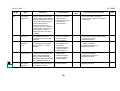
One-tray Paper Feed Unit (500 sheets x 1)
Item
Relay Roller
Bottom Plate Pad
20K
50K
100K
Two-tray Paper Feed Unit (500 sheets x 2)
Item
Relay Roller
Bottom Plate Pad
20K
50K
100K
150K
1,000K
EM
C
C
Remarks
Damp cloth
Damp cloth
20K
50K
100K
150K
1,000K
EM
C
C
Remarks
Damp cloth
Damp cloth
20K
50K
100K
150K
20K
50K
100K
150K
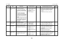
LCT (2000 sheets)
Item
Relay Roller
Bottom Plate Pad
Two-tray Finisher
Items
Rollers
Discharge Brush
Sensors
Jogger Fences
1,000K
EM
C
C
C
I
Remarks
Damp cloth
Dry cloth
Blower brush
Replace if required.
Four-bin Mailbox
Item
Rollers
Tray Paper Sensors
1,000K
EM
C
C
2-3
Remarks
Damp cloth
Blower blush or dry
cloth
Preventive
Maintenance
2.2 SERVICE MAINTENANCE
30 July, 2001
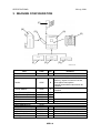
SPECIAL TOOLS
3. REPLACEMENT AND ADJUSTMENT
!CAUTION
Turn off the main switch and unplug the machine before beginning any of
the procedures in this section.
" : Connector
Replacement
Adjustment
NOTE: This manual uses the following symbols.
☛ : See or refer to
! : Screw
# : Clip ring
$ : E ring
3.1 SPECIAL TOOLS
Part Number
A2309352
G0219350
C4019503
Part Name
Flash Memory Card - 4MB
Loop-back connector - Parallel
20X Magnification Scope
3-1
Q’ty
1
1
1
IMAGE ADJUSTMENT
30 July, 2001
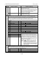
3.2 IMAGE ADJUSTMENT
3.2.1 REGISTRATION
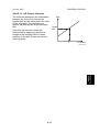
Image Area
The image area shown in the
illustration must be guaranteed. So
A
make sure that the registration is
adjusted within the adjustment standard
range as described below.
B
Feed direction
Image Area
C
A = B = C = 4.2mm (1.6")
G060R007.WMF
Leading Edge
Adjusts the leading edge registration for each paper type and process line speed.
Side to Side
Adjusts the side to side registration for each paper feed station.
NOTE: The side to side registration for the optional paper feed unit, LCT, and
duplex unit can be adjusted with SP mode or with the user tools
(Maintenance menu).
Adjustment Standard
• Leading edge (sub-scan direction):
• Side to side (main-scan direction):
3 ± 0 mm
2 ± 0 mm
Paper Registration Standard
The registration in both main and sub-scan direction may fluctuate within the
following tolerance.
1st side
• Sub-scan direction:
• Main-scan direction:
2nd side in duplex
• Sub-scan direction:
• Main-scan direction:
0 ± 1.5 mm
0 ± 2 mm
0 ± 3 mm
0 ± 4 mm
3-2
30 July, 2001
IMAGE ADJUSTMENT
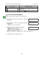
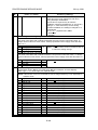
Adjustment Procedure
1. Enter SP mode and access SP5-997.
3. Perform the leading edge registration adjustment.
1) Check the leading edge registration and adjust it with SP1-001.
2) Select the adjustment conditions (paper type and process line speed).
3) Input the value then press the [Escape] key.
4) Check the leading edge adjustment by generating the trim pattern.
4. Perform the side to side registration adjustment.
1) Check the side to side registration and adjust it with SP1-002.
2) Select the adjustment conditions (paper feed station).
3) Input the value then press the [Escape] key.
4) Check the side to side adjustment by generating the trim pattern.
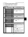
3.2.2 COLOR REGISTRATION
Line Position Adjustment
Normally, the automatic line position adjustment is executed under a specified
condition to optimize the color prints. If color registration shifts, execute “Auto
Adjust” with the user tools (Maintenance menu – Color registration) or SP5-993-2
to do the forced line position adjustment. In addition, it is recommended to perform
the line position adjustment under the following conditions:
•
After transporting or moving the printer (if printers are pre-installed at the
workshop and transported to the user location, forced line position adjustment
should be done after printer installation is completed at the user location.)
• When opening the drum positioning plate
• When removing or replacing the motors, clutches, and/or gears related to the
drum/development/transfer sections
• When removing or replacing the transfer belt or laser optical housing unit
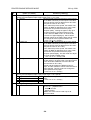
Adjustment for Line Speed of Fusing Unit
Optimize the line speed for the fusing unit when the color registration shifts more
on the trailing edge compared with that on the leading edge, even after line
position adjustment is executed. Adjust the speed of development motor-K with the
following user tool in the Maintenance menu.
“Menu/Maintenance/Color Regist./Fuser Adjust/Custom Adjust”
Refer to Maintenance Guide 1 of the Operating Instructions for how to adjust this.
3-3
Replacement
Adjustment
2. Print out the pattern (14: 1-dot trimming pattern) with SP5-997.
NOTE: Registration may change slightly print by print as shown above.
Therefore print a few pages of the trimming pattern for step 3 and 4,
and average the leading edge and side-to-side registration values and
adjust each SP mode.
IMAGE ADJUSTMENT
30 July, 2001
3.2.3 PRINTER GAMMA
NOTE: Normally, the printer gamma is enough to adjust the color balance to
archive the optimum print output. The gamma correction is only required
for fine-tuning to meet the user requirements.
Adjustment Overview
Make the gradation scales on the printout smooth from the highlight to the shadow
density. Adjust the CMY gradation scale at the top of the chart by balancing the
density of the C, M, and Y gradation scales – the CMY gray scale should change
smoothly from minimum to maximum, and there should be no coloration.
For each color, you can adjust 15 points between 0 (lowest density) and 255
(highest density).
The gradation scales marked ‘Default Value’ are printed according to the default
gamma settings. The gamma adjustment changes the densities at the adjustable
points in the gradation scale. The gradation scale marked “Current Value” shows
the current settings.
During the adjustment procedure, compare the “Current Value” gradation scale
with the ‘Default Value’. Select the density for each of the 15 adjustable points,
excluding points 0 and 255, from the ‘Default Value’ gradation scale.
The NVRAM holds three printer gamma settings, those saved this time (Current),
those saved in the preceding adjustment (Previous), and the factory settings
(Factory).
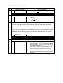
Adjustment Procedure
1. Enter SP mode.
2. Select “1.Service”.
3. Select “Data Recall” and load the settings that will serve as the base for the
adjustment.
4. Select “Mode Selection”, and select the print mode that you are going to adjust.
5. To review the image quality for these settings, choose “Test Page” to print out a
color calibration test sheet.
6. Select “Gamma Adj.”.
7. Adjust the color density at each of the 15 points for a color (CMY and K).
8. When the density setting is complete for all colors, print out a color calibration
test sheet again and make sure that the gradation scale for each printed color
is smooth and that the CMY gradation scale is gray. Repeat the adjustment if
there is an anomaly.
9. If the adjustment results prove satisfactory, execute “Data Save”.
3-4
30 July, 2001
EXTERIOR COVERS
3.3 EXTERIOR COVERS
3.3.1 REAR COVER AND UPPER REAR COVER
[B]
1. Rear cover [A] (! x 4, 2 hooks)
2. Remove the optional mailbox if it is
installed.
3. Upper exit cover [B] (1 hook), if the
optional mailbox is not installed.
[D]
4. Open the upper right cover [C].
5. Upper rear cover [D] (! x 4)
[A]
G060R201.WMF
3.3.2 PAPER EXIT TRAY
1. Paper exit tray [A] (! x 2)
[A]
G060R202.WMF
3.3.3 UPPER RIGHT COVER
[B]
1. Right cover [A] (! x 2)
NOTE: To loosen the screws, close
the upper right cover; to
remove the right cover, open
the upper right cover.
2. Upper right cover [B]
[A]
G060R204.WMF
3-5
Replacement
Adjustment
[C]
EXTERIOR COVERS
30 July, 2001
3.3.4 FRONT COVER
1. Front cover [A] (2 pins)
[A]
G060R410.WMF
3.3.5 LEFT COVER AND REAR LEFT COVER
1. Remove the optional finisher from the
printer if it is installed.
2. Remove the optional duplex inverter
unit if it is installed.
[A]
3. Connector cover [A], if the optional
duplex unit is not installed
4. Left cover [B] (! x 6)
[B]
G060R714.WMF
[D]
5. Open the left door [C].
[C]
6. Rear left cover [D] (! x 3)
G060R717.WMF
3-6
30 July, 2001
EXTERIOR COVERS
3.3.6 UPPER LEFT COVER AND OPERATION PANEL
[B]
1. Open the front cover.
2. Open the upper right cover
3. Operation panel [A] (! x 2, " x 2, 2
hooks)
4. Upper left cover [B] (! x 2, 1 hook)
G060R716.WMF
3-7
Replacement
Adjustment
[A]
LASER OPTICS
30 July, 2001
3.4 LASER OPTICS
!WARNING
Turn off the main switch and unplug the machine before beginning any of
the procedures in this section. Laser beams can cause serious eye injury.
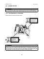
3.4.1 CAUTION DECAL LOCATIONS
Caution decals are placed as shown below.
LASER CAUTION 1.TIF
G060R203.WMF
LASER CAUTION 2.TIF
! WARNING
Be sure to turn off the main switch and disconnect the power plug from the
power outlet before beginning any disassembly or adjustment of the laser
unit. This printer uses a class IIIb laser beam with a wavelength of 655 nm
and an output of 7 mW. The laser can cause serious eye injury.
3-8
30 July, 2001
LASER OPTICS
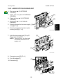
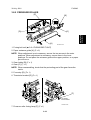
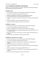
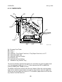
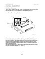
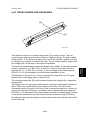
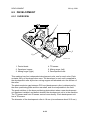
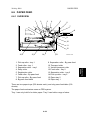
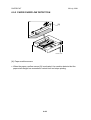
3.4.2 LASER OPTICS HOUSING UNIT
1. Rear cover (☛ 3.3 EXTERIOR
COVERS)
[A]
2. Upper rear cover (☛ 3.3 EXTERIOR
COVERS)
3. Paper exit tray (☛ 3.3 EXTERIOR
COVERS)
[B]
4. Right cover (☛ 3.3 EXTERIOR
COVERS)
Replacement
Adjustment
5. Securing screws for the toner supply [A]
unit [A] (! x 4)
6. Securing screws for the laser optics
housing unit [B] (! x 2)
G060R205.WMF
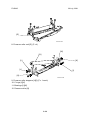
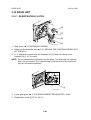
7. Hold the toner supply unit [C] up ➀.
Then, lower the unit ➁.
NOTE: The pin [D] for the front and
rear shafts holds the toner
supply unit.
[C]
[D]
G060R206.WMF
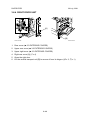
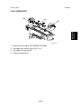
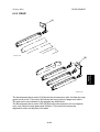
8. Connector cover [E] (! x 1)
9. Four flat cables [F]
[F]
10. Connector [G]
[E]
[G]
3-9
G060R207.WMF
LASER OPTICS
30 July, 2001
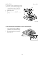
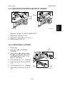
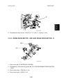
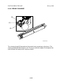
11. Flat cable bracket [G] (! x 1)
12. Cable (clamps [H])
[G]
[H]
G060R208.WMF
[I]
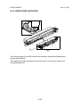
13. Duct [I]
14. Laser optics housing unit (! x 2)
NOTE: Hold the unit with both hands
and slowly lift up.
15. After reinstalling the laser optics
housing unit, do some adjustments (☛
the procedures on the following page).
NOTE: When pulling the laser optics
housing unit up, make sure that
the flat cables from the laser diode
board are not caught by the
G060R209.WMF
brackets. If you roughly remove
the unit without paying attention to this point, the cables will be caught by
bracket and the laser diode board may be damaged.
To ensure that the unit is removed carefully, remove the unit by placing a
sheet of paper between the laser optic housing unit and the machine rear
frame, in order to prevent the cables from being caught by the brackets.
After installing the laser optics housing unit, do forced line position adjustment
(SP5-993-002 or ‘Maintenance – Color Registration - Auto Adjust’ in User Program
mode).
3-10
30 July, 2001
LASER OPTICS
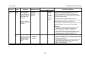
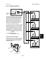
Adjustments after Replacing the Laser Optics Housing Unit
1. Enter SP mode.
Decal 1
Decal 2
Value on the left
SP2-109-3
SP2-994-4
Value on the right
SP2-109-2
SP2-994-3
Decal 3
SP2-994-2
SP2-994-1
Decal 3
Decal 2
Decal 1
Jp:xxxxx P:46,41
600dpi
Function
Laser beam pitch
Main-scan registration
correction for black and cyan
Main-scan registration
correction for magenta and
yellow
Jp:xxxxx KC:-2,-2
K
1200dpi
Jp:xxxxx MY:-2,-2
C
M
G060R004.WMF
G060R005.WMF
Y
G060R006.WMF
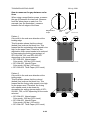
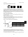
3. Print out the following test pattern (17: cross-stitch main-scan) with SP5-997.
4. Check these test patterns. If the laser beam pitch is not correct, vertical black
strips seem to appear.
• Cross-stitch pattern: The thin lines should be of uniform thickness (no striping
effect should appear on the printout).
5. Adjust the laser beam pitch values in SP2-109-2 and -3 until the printout is
correct, as shown below.
Feed direction
Adjustment not completed
Adjustment completed
G060R002.WMF
6. Execute SP5-993-2 or “Auto Adjust” with the Maintenance menu in the user
tools.
3-11
Replacement
Adjustment
2. Input the values printed on three decals on the new laser optics housing unit
into the following SPs. Each decal contains two values.
LASER OPTICS
30 July, 2001
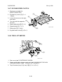
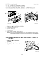
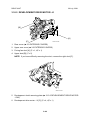
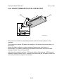
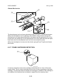
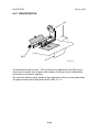
3.4.3 POLYGON MIRROR MOTOR
[A]
1. Laser optics housing unit (☛ 3.4.2
LASER OPTICS HOUSING UNIT)
[B]
2. Cover [A] (! x 4)
3. Polygon mirror motor [B] (! x 4 and
" x 1)
G060R210.WMF
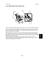
3.4.4 LASER SYNCHRONIZING DETECTOR BOARDS
1. Laser optics housing unit (☛ 3.4.2
LASER OPTICS HOUSING UNIT)
2. Synchronizing detector boards [A]
(! x 1, " x 2)
[A]
G060R211.WMF
3-12
30 July, 2001
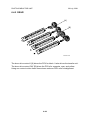
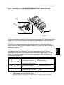
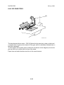
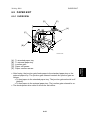
PCU AND DEVELOPMENT UNIT
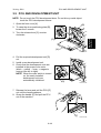
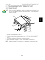
3.5 PCU AND DEVELOPMENT UNIT
NOTE: Do not touch the PCU development drum. Do not let any metal object
touch the PCU development sleeve.
1. Open the front cover [A].
[B]
2. To raise the drum positioning plate [B],
loosen the 2 screws.
3. Turn the release lever [C] counterclockwise.
Replacement
Adjustment
[C]
[A]
G060R301.WMF
4. Pull the required development unit [D]
out.
5. Install a new development unit.
6. Check that the development units are
installed in the proper color order
(black → yellow → cyan → magenta
moving from left to right).
NOTE: When the main switch is turned
on, the newly installed
development units are
automatically initialized.
7. Release the lever and pull the PCU [E]
out until the handle appears.
[D]
G060R302.WMF
[E]
8. Grasp the handle [F] and pull the PCU
out of the machine.
[F]
G060R303.WMF
3-13
PAPER FEED
30 July, 2001
3.6 PAPER FEED
3.6.1 PICK-UP, FEED, AND SEPARATION ROLLERS
Tray 1 and Tray 2
1. Tray 1 and Tray 2
2. Pick-up roller [A] (1 hook)
3. Feed roller [B] (# x 1)
[B]
4. Separation roller [C] (# x 1)
[A]
By-pass Tray
[C]
G060R101.WMF
[A]
1. Open the right door.
2. By-pass tray cover [A] (1 hook, ! x 1)
3. Raise the paper end sensor actuator.
4. Pick-up roller [B] (1 hook)
[B]
G060R102.WMF
5. Feed roller [C] (# x 1)
[C]
6. Separation roller [D] (# x 1)
[D]
G060R110.WMF
3-14
30 July, 2001
PAPER FEED
3.6.2 PAPER WIDTH DETECTION BOARD
[D]
[A]
Replacement
Adjustment
[B]
[C]
G060R103.WMF
1. Open the by-pass tray.
2. Center the side fences [A].
3. By-pass tray cover [B] (! x 2, 2 hooks)
4. There is a square hole [C] on each side of the tray. Insert a screwdriver into
each of the holes.
5. Paper width detection board [D] (! x 1, " x 1)
3.6.3 VERTICAL TRANSPORT SENSOR
[B]
[A]
G060R104.WMF
1. Open the right door.
2. Vertical transport cover [A] (! x 4)
3. Vertical transport sensor [B] (" x 1)
3-15
PAPER FEED
30 July, 2001
3.6.4 RIGHT DOOR UNIT
[A]
[B]
G060R105.WMF
G060R106.WMF
1. Rear cover (☛ 3.3 EXTERIOR COVERS)
2. Upper rear cover (☛ 3.3 EXTERIOR COVERS)
3. Upper right cover (☛ 3.3 EXTERIOR COVERS)
4. Right rear cover [A] (! x 4)
5. Open the right door.
6. Lift the vertical transport unit [B] to remove it from its hinges (" x 3, # x 1).
3-16
30 July, 2001
PAPER FEED
3.6.5 REGISTRATION SENSOR AND RELAY SENSOR
[C]
[A]
Replacement
Adjustment
[B]
G060R109.WMF
G060R108.WMF
1. Right door unit (☛ 3.6.4 RIGHT DOOR UNIT)
2. Registration guide [A] (! x 2)
3. Registration sensor [B] (! x 2, " x 1)
4. Relay sensor [C] (" x 1)
3.6.6 PAPER FEED CLUTCHES
1. Paper trays
[B]
2. Rear cover (☛3.3 EXTERIOR
COVERS)
3. Swing out the high voltage supply
unit (☛3.9.2 MOVING THE HIGH
VOLTAGE SUPPLY UNIT - C, B
OUT OF THE WAY).
[A]
4. Clutch holder [A] (! x 2, 1 bearing)
5. Paper feed clutch for tray 1 [B] ("
x 1)
6. Clutch holder [C] (! x 2, 1 bearing)
7. Paper feed clutch for tray 2 [D] ("
x 1)
[D]
[C]
G060R713.WMF
3-17
PAPER FEED
30 July, 2001
3.6.7 BY-PASS FEED CLUTCH
1. Right door unit (☛3.6.4
RIGHT DOOR UNIT)
2. By-pass tray cover [A] (! x 1,
1 hook)
3. Loosen the screw on the right
door latch.
[C]
4. Turn the latch the opposite
direction.
[A]
[E]
[B]
5. Upper guide plate [B] (! x 4)
6. Support plate [C] ($ x 2)
G060R107.WMF
[D]
7. Relay gear [D] (1 hook)
8. By-pass feed clutch [E] (" x 1)
3.6.8 TRAY LIFT MOTOR
[A]
[B]
G060R712.WMF
1. Rear cover (☛ 3.3 EXTERIOR COVERS)
2. Swing out the high voltage supply unit. (☛ 3.9.2 MOVING THE HIGH
VOLTAGE SUPPLY UNIT - C, B OUT OF THE WAY)
3. Tray lift motors (tray 1 [A], tray 2 [B]) (! x 2, " x 1)
3-18
30 July, 2001
TRANSFER AND PAPER TRANSPORT UNIT
3.7 TRANSFER AND PAPER TRANSPORT UNIT
3.7.1 TRANSFER UNIT
NOTE: When removing or installing the transfer unit, grasp the central areas of the
front and rear frame. Do not touch the transfer belt [A]. Do not damage the
entrance mylar [B].
Replacement
Adjustment
[A]
[B]
[D]
[C]
G060R811.WMF
1. Transfer unit lock bracket [C] (! x 1)
2. Turn the release lever counterclockwise. (☛ 3.5 PCU AND DEVELOPMENT
UNIT)
3. Pull out the transfer unit [D] until the entire unit is visible.
4. Grasp the transfer unit grips as shown above. Lift the unit to remove it.
NOTE: Grasp the front grip. Use caution not to damage the actuator on the rear.
3-19
TRANSFER AND PAPER TRANSPORT UNIT
[C]
30 July, 2001
[B]
[A]
[E]
[D]
[G]
[F]
G060R823.WMF
G060R824.WMF
NOTE: To minimize the amount of color shift, the position of the drive gears is
controlled at the factory, to stabilize the rotation of the gears. Before
installing the transfer unit, adjust the position of the gears according to the
procedure below.
1) Rotate the transfer unit cleaning drive gear [A] counterclockwise until
the mark [B] on the transfer unit drive gear aligns horizontally with the
gear shaft [C]. After adjusting the gear position, check the position of the
mark, keeping your eyes at the same height as the mark. Rotate the
cleaning drive gear [A] either clockwise or counterclockwise for fine
position adjustment.
2) Rotate the transfer belt drive gear [D] on the transfer unit clockwise until
the mark [E] on the gear and the centers of the shafts are on a line [F]
which is parallel to the lower edge of the left bracket [G].
After replacing the transfer unit:
• Perform forced line position adjustment (SP5-993-002 or ‘Maintenance menu –
Color Registration - Auto Adjust’ in User Program mode),
• Print the 1-dot grid pattern on A3/11"x17" paper and check the color shift level
(☛ 4.4.3 Color Shift After Transfer Unit Replacement).
3-20
30 July, 2001
TRANSFER AND PAPER TRANSPORT UNIT
3.7.2 TRANSFER BELT CLEANING UNIT
Replacement
Adjustment
[A]
G060R810.WMF
1. Turn the release lever counterclockwise (☛ 3.5 PCU AND DEVELOPMENT
UNIT).
2. Pull out the transfer unit until the entire unit is visible (☛ 3.7.1 TRANSFER
UNIT).
3. Transfer cleaning unit [A] (! x 1, 3 pins).
NOTE: When reassembling, check that the transfer unit lock bracket (☛ 3.7.1
TRANSFER UNIT) is installed and that the transfer unit release lever is put
back to the original position (☛ 3.5 PCU AND DEVELOPMENT UNIT).
After replacing the transfer belt cleaning unit, perform forced line position
adjustment (SP5-993-002 or ‘‘Maintenance menu – Color registration - Auto Adjust’
in User Program mode).
3-21
TRANSFER AND PAPER TRANSPORT UNIT
30 July, 2001
3.7.3 CLEANING BLADE AND CLEANING ROLLER
[F]
[C]
[G]
[B]
[A]
[E]
G060R403.WMF
[D]
1. Transfer belt cleaning unit (☛ 3.7.2 TRANSFER BELT CLEANING UNIT)
2. Front gear [A] ($ x1, 1 bearing with the bias terminal)
3. Rear gear [B] (1 hook, 1 bearing)
4. Cleaning bias roller [C]
5. Idle gear [D]
6. Bushings [E][F] (1 spring for each)
NOTE: The front and rear bushings have different springs.
Front: a long, thin, silvery spring
Rear: a short, thick, black spring
7. Cleaning blade [G] (1 bearing)
After replacing the cleaning blade, perform forced line position adjustment (SP5993-002 or ‘‘Maintenance menu – Color registration - Auto Adjust’ in User Program
mode).
3-22
30 July, 2001
TRANSFER AND PAPER TRANSPORT UNIT
3.7.4 TRANSFER BELT
NOTE: Do not touch the transfer belt during handling. When replacing the belt,
hold the belt at its end.
[E]
[A]
Replacement
Adjustment
[B]
[C]
[D]
G060R815.WMF
1. Transfer unit (☛ 3.7.1 TRANSFER UNIT)
2. Transfer cleaning unit (☛ 3.7.2 TRANSFER BELT CLEANING UNIT)
3. Release lever [A] (! x 1)
4. ! [B] x 1
5. Transfer exit guide [C] (! x 1, 1 step screw)
6. Left bracket [D] (! x 2, " x 1)
NOTE: Make sure that the grounding plate [E] is in the correct position when
reinstalling the left bracket.
3-23
TRANSFER AND PAPER TRANSPORT UNIT
30 July, 2001
[J]
[I]
[H]
G060R812.WMF
[F]
[G]
7. High voltage wire [F] (! x 1)
NOTE: When reassembling, secure the screw while pressing the wire down to
prevent it from touching the PCUs.
8. Wire contact [G]
9. Transfer entrance guide [H] (! x 2)
10. Grounding plate [I] (! x 1)
11. Right bracket [J] (! x 1)
Reassembly
➀ Set the transfer entrance guide in
position.
➁ Hold up the transfer entrance guide.
➂ Screw the transfer entrance guide into
position.
G060R813.WMF
3-24
30 July, 2001
TRANSFER AND PAPER TRANSPORT UNIT
[M]
[N]
[O]
[L]
Replacement
Adjustment
[P]
G060R801.WMF
[K]
12. Two tension springs [K][L]
CAUTION: Be careful that the springs do not jump out when removing or
reinstalling.
13. Unhook the gear [M] (1 spacer, 1 bushing)
14. Raise the actuator [N] and remove the roller-holder plate [O] ($ x 1, 1 bushing)
NOTE: The front and rear roller-holder plates are greased. Do not touch the
grease. If the grease has been wiped off, apply grease G-501 or Barrierta
S552R to the same place.
15. Transfer belt roller [P] ($ x 1, 1 bushing, 1 gear)
Reassembly
➀ Set the left end of the spring.
➁ Pull the transfer belt roller to the
right.
➂ Set the right end of the spring.
➃ Check that the spring is straight.
➄ Press the front end of the gear
shaft to properly set the gear on the
shaft.
OK
NG
G060R814.WMF
3-25
TRANSFER AND PAPER TRANSPORT UNIT
30 July, 2001
[Q]
16. Lay the transfer unit on its side. Grasp
the upper end of the transfer belt and
pull the transfer belt [Q] up and out.
17. When reinstalling the belt, check that
the end with the belt-lot number comes
to the rear side of the machine.
[R]
G060R816.WMF
NOTE: 1) If the transfer charge brushes are dirty, clean them with a vacuum
cleaner.
2) If the drive rollers are dirty, clean them with a damp cloth.
3) When reassembling, check that the connector [R] is outside the transfer
belt.
.
After replacing the transfer belt, perform forced line position adjustment (SP5-993002 or ‘Maintenance menu – Color registration - Auto Adjust’ in User Program
mode).
3-26
30 July, 2001
TRANSFER AND PAPER TRANSPORT UNIT
3.7.5 OTHERS
Front Plate
Normally, you do not have to remove the front plate [A]. If, however, the front plate
is removed, make sure that projections [B] fit in the screw holes [C] when
reassembling. If not, the transfer belt moves to the rear or front end.
[A]
Replacement
Adjustment
[B]
[C]
[D]
G060R817.WMF
Grounding Spring
When reassembling the transfer unit, make sure that the grounding spring [D] is in
the correct position. If the spring is out of position and not in contact with the front
plate, high voltage leak may occur, causing a malfunction.
Drive Gear and Left Drive Roller
[D]
[E]
[B]
[C]
[A]
G060R820.WMF
Normally, you do not have to remove the drive gear [A], the left drive roller [B], and
the timing belt [C]. If, however, any of these is removed, make sure that the drive
gear mark [D] and the left drive roller mark [E] are positioned at the top when
reassembling. If the gear and roller are not positioned as shown, this may cause
the transfer belt speed to fluctuate slightly, resulting in color shifts.
3-27
FUSING
30 July, 2001
3.8 FUSING
!CAUTION
1. Be careful when handling the fusing unit. It is very hot.
2. Take care not to spill silicone oil.
3.8.1 FUSING UNIT
[A]
G060R508.WMF
1. Detach the finisher from the printer if it is installed.
2. Open the duplex inverter unit if it is installed.
3. Fusing unit [A]
After replacing the fusing unit, optimize the line speed for fusing unit by adjusting
the speed of development motor-K with the Maintenance menu in the user tools
“Menu/Maintenance/Color Regist./Fuser Adjust/At Unit Replace”.
This mode is automatically required after the machine detects a new fusing unit is
installed. Refer to Maintenance Guide 1 of the Operating Instructions for how to
adjust this.
3-28
30 July, 2001
FUSING
3.8.2 OIL SUPPLY UNIT
Replacement
Adjustment
[A]
G060R509.WMF
1. Detach the finisher from the printer if it is installed.
2. Open the duplex inverter unit if it is installed.
3. Fusing unit (☛ 3.8.1 FUSING UNIT)
4. Oil supply unit [A]
3.8.3 UPPER COVER
[A]
[C]
[D]
[B]
G060R501.WMF
1. Oil supply unit [A]
2. Knob [B] (! x 1)
3. Oil unit separation lever [C] (! x 1)
4. Upper cover [D] (Step screw x 1, ! x 3)
3-29
FUSING
30 July, 2001
3.8.4 FUSING BELT UNIT
[A]
➁
➂
➀
G060R502.WMF
1. Upper oil supply/cleaning unit [A] (! x 3)
NOTE: When reassembling, secure 3 screws temporarily first. Then, tighten the
screws in the following order (➀→➁→➂). If the screws are not tightened in
this order, the drive gears are not properly engaged, causing mechanical
noise.
[B]
[E]
[D]
[C]
G060R802.WMF
2. Lower paper guide plate [B] (Step screw x 1, ! x 1)
NOTE: When reassembling, insert the hook [C] into the lower cover groove [D].
Otherwise, the plate bends slightly and the pick-off pawls may damage the
pressure roller. After reinstalling the plate, push the central portion [E]
down to make sure that the plate is in position.
3-30
30 July, 2001
FUSING
[H]
[E]
[G]
G060R506.WMF
3. Pressure springs [E]
4. Belt tension springs [F][G]
5. ! x 4 [H]
[J]
[K]
[I]
G060R507.WMF
6. Pressure brackets [I]
NOTE: If you have difficulty removing the brackets, press down one of the places
indicated by the arrows [J][K].
3-31
Replacement
Adjustment
[F]
FUSING
30 July, 2001
[L]
US: 770W
EU/AA: 700W
[M]
G060R803.WMF
7. Heating roller fusing lamp [L] (! x 2)
NOTE: 1) The voltage and wattage are etched on the lamp terminals.
2) The fusing unit provided as a maintenance kit has the detection board
[M]. The unit that comes with the machine does not have this.
[P]
[O]
[N]
G060R821.WMF
8. Fuse terminal [N] (! x 1)
9. Thermistor connector [O] (" x 1)
10. Pull the fusing belt unit [P] up and remove it.
3-32
30 July, 2001
FUSING
3.8.5 PRESSURE ROLLER
[E]
[B]
[C]
Replacement
Adjustment
[D]
[A]
G060R804.WMF
1. Fusing belt unit (☛ 3.8.4 FUSING BELT UNIT)
2. Paper entrance guide [A] (! x 2)
NOTE: When adjustment is not necessary, secure the two screws in the outer
positions. When adjustment is necessary, secure them in the inner
positions. Do not place the entrance guide at the upper position, or a paper
jam will occur.
3. Gear holder [B] (! x 1)
4. Gear [C] ($ x 1)
NOTE: When reassembling, check that the protruding part of the gear faces the
inside.
5. Fuse stay [D] (! x 1)
6. Thermistor bracket [E] (! x 1)
[F]
US: 350W
EU/AA 325W
G060R803.WMF
7. Pressure roller fusing lamp [F] (! x 1)
3-33
FUSING
30 July, 2001
[G]
G060R805.WMF
8. Pressure roller unit [G] (! x 4)
[M]
[N]
[K]
[L]
[J]
[I]
[H]
G060R806.WMF
9. Pressure roller stoppers [H][I] (! x 1 each)
10. C rings [J][K]
11. Bearings [L][M]
12. Pressure roller [N]
3-34
30 July, 2001
FUSING
3.8.6 PAPER EXIT
[B]
[A]
Replacement
Adjustment
[C]
G060R601.WMF
1. Paper exit cover (☛ 3.3 EXTERIOR COVERS)
2. Exit upper limit sensor cover [A] (! x 2)
3. Exit upper limit sensor [B]
4. Paper exit sensor [C]
3-35
ELECTRICAL COMPONENTS
30 July, 2001
3.9 ELECTRICAL COMPONENTS
3.9.1 MOVING THE CONTROLLER BOX OUT OF THE WAY
[D]
[B]
[A]
[C]
G060R704.WMF
G060R705.WMF
1. Rear cover (☛ 3.3 EXTERIOR COVERS)
2. Connector cover [A] (! x 1)
3. Four flat cables [B]
4. Connector [C]
5. Swing out the controller box [D] (! x 4).
NOTE: When the controller box is swung out, free-run tests can still be done.
However, because the LD cables are disconnected, no output appears.
3.9.2 MOVING THE HIGH VOLTAGE SUPPLY UNIT - C, B OUT OF
THE WAY
1. Rear cover (☛ 3.3 EXTERIOR
COVERS)
2. Swing out the high voltage supply unit
[A] (! x 2).
[A]
G060R711.WMF
3-36
30 July, 2001
ELECTRICAL COMPONENTS
3.9.3 CONTROLLER AND BCU
NOTE: After replacing the BCU or controller, remove the NVRAM on the old board
and install it on the new board.
[B]
1. Controller [A] (! x 2)
2. Option bracket [B] (! x 2)
Replacement
Adjustment
3. Rear cover [C] (☛3.3 EXTERIOR
COVERS)
[A]
[C]
G060R701.WMF
4. Cover bracket [D] (! x 3)
5. Inner bracket [E] (! x 2)
[D]
[E]
G060R702.WMF
[F]
6. Connector cover [F] (! x 1)
7. BCU [G] (! x 8, " x 23)
NOTE: After replacing the BCU or controller,
remove the NVRAM on the old board
and install it on the new board. If the
NVRAM on the old board is defective,
replace the NVRAM (☛ 3.9.4 NVRAM
REPLACEMENT PROCEDURE).
[G]
G060R703.WMF
3-37
ELECTRICAL COMPONENTS
30 July, 2001
3.9.4 NVRAM REPLACEMENT PROCEDURE
Make sure you have the SMC report (factory settings) that comes with the printer
before beginning the following procedure.
NVRAM for BCU
1. Enter SP mode and print out the SMC reports with SP5-990 if possible.
2. Turn off the main switch and unplug the power cord.
3. Replace the NVRAM on the BCU and reassemble the machine.
4. Execute the RAM clear for engine settings with SP5-801-2.
5. Contact your supervisor to enter the machine’s device number and destination
code.
6. Reset the settings for meter charge with SP5-930-1 to -5.
7. Enter the SP mode changes at the factory and the field.
NVRAM for Controller
1. Enter SP mode and print out the SMC reports with SP5-990 if possible.
2. Turn off the main switch and unplug the power cord.
3. Replace the NVRAM on the controller and reassemble the machine.
4. Execute the RAM clear for controller settings and counters with SP5-801-3, -8,
-11, and SP7-808-1.
5. Reset the total counter to 0 (SP7-825-1) if meter charge mode (SP5-930-1) is
enabled.
6. Enter the SP mode changes at the factory and the field.
NVRAMs for both BCU and Controller
1. Enter SP mode and print out the SMC reports with SP5-990 if possible.
2. Turn off the main switch and unplug the power cord.
3. Replace the NVRAM on the BCU and the controller, and reassemble the
machine.
4. Execute the RAM clear with SP5-801-1 and SP7-808-1.
5. Contact your supervisor to enter the machine’s device number and destination
code.
6. Reset the settings for meter charge with SP5-930-1 to -5.
7. Reset the total counter to 0 (SP7-825-1) if meter charge mode (SP5-930-1) is
enabled.
8. Enter the SP mode changes at the factory and the field.
3-38
30 July, 2001
ELECTRICAL COMPONENTS
[A]
G060R710.WMF
1. Rear cover (☛ 3.3 EXTERIOR COVERS)
2. High voltage supply board [A] (! x 6, " x 16)
3.9.6 PSU
[A]
G060R715.WMF
1. Left cover (☛3.3 EXTERIOR COVERS)
2. PSU [A] (! x 5, " x 12)
NOTE: Check that the interlock switches on the PSU work normally after
reinstalling the PSU (open/close the left and front doors).
3-39
Replacement
Adjustment
3.9.5 REMOVING THE HIGH VOLTAGE SUPPLY BOARD - C, B
DRIVE UNIT
30 July, 2001
3.10 DRIVE UNIT
3.10.1 REGISTRATION CLUTCH
[A]
[D]
[B]
[C]
G060R808.WMF
1. Rear cover (☛ 3.3 EXTERIOR COVERS)
2. Swing out the controller box (☛ 3.9.1 MOVING THE CONTROLLER BOX OUT
OF THE WAY).
3. K, C, and M drum gears with the flywheels [A]∼[C] and color drum motor
flywheel [D] (! x 1 for each)
NOTE: Do not separate the flywheels from the gears. The flywheels are secured
with nuts and screws. The nuts will drop in the rear side of the machine if
they are not secured properly.
[I]
G060R706.WMF
4. Lower gear guide (☛ 3.10.3 DEVELOPMENT DRIVE MOTOR - CMY)
5. Registration clutch [I] (" x1, # x 1)
3-40
30 July, 2001
DRIVE UNIT
[A]
G060R819.WMF
1. Rear cover (☛ 3.3 EXTERIOR COVERS)
2. Swing out the controller box (☛ 3.9.1 MOVING THE CONTROLLER BOX OUT
OF THE WAY).
3. K, C, and M drum gears, with the flywheels (☛ 3.10.1 REGISTRATION
CLUTCH)
4. Y drum gear (! x 1) (☛ 3.10.1 REGISTRATION CLUTCH)
5. Lower gear guide (☛ 3.10.3 DEVELOPMENT DRIVE MOTOR - CMY)
NOTE: To remove the B, Y, and C development clutches, you do not have to
remove the lower gear guide.
6. Development clutches [A] (! x 1 for each, # x 1 for each)
Case 1
Case 2
G060R825.WMF
NOTE: When reassembling the machine, please route the development clutch
cables as shown in the bottom half of the illustration, or problems will
occur. If the cables are routed as shown in Case 1, the black and yellow
development clutch cables are connected the other way around, causing
an abnormal image (no black or yellow). If the cables are routed as shown
in Case 2, the power lines for the clutches are connected incorrectly,
causing damage to the BCU board.
3-41
Replacement
Adjustment
3.10.2 DEVELOPMENT CLUTCHES
DRIVE UNIT
30 July, 2001
3.10.3 DEVELOPMENT DRIVE MOTOR - CMY
[A]
[C]
[D]
[F]
[B]
[E]
G060R809.WMF
1. Rear cover (☛ 3.3 EXTERIOR COVERS)
2. Upper gear guide [A] (! x 4)
3. Lower gear guide [B] (! x 5)
4. Development clutches (☛ 3.10.2 DEVELOPMENT CLUTCHES)
5. Three gears [C]∼[E]
6. Timing belt [F]
[G]
[H]
[I]
[J]
[K]
G060R818.WMF
7. Four gear drive holders [G]∼[J] (! x 1 for each)
8. Development clutch securing plate [K] (! x 8, " x 2)
3-42
30 July, 2001
DRIVE UNIT
Replacement
Adjustment
[L]
G060R709.WMF
9. Development drive motor - CMY [L] (! x 5, " x 3, 1 spring, 1 belt)
3.10.4 DRUM DRIVE MOTOR - CMY AND DRUM DRIVE MOTOR - K
[B]
[A]
G060R725.WMF
1. Rear cover (☛ 3.3 EXTERIOR COVERS)
2. Development clutch securing plate (☛ 3.10.3 DEVELOPMENT DRIVE MOTOR
- CMY)
3. Drum drive motor - CMY [A] (! x 2)
4. Drum drive motor - K [B] (! x 2)
3-43
DRIVE UNIT
30 July, 2001
3.10.5 DEVELOPMENT DRIVE MOTOR - K
[B]
[A]
[C]
G060R718.WMF
1. Rear cover (☛ 3.3 EXTERIOR COVERS)
2. Upper rear cover (☛ 3.3 EXTERIOR COVERS)
3. Fusing fan duct [A] (! x 1, " x 1)
4. Upper duct [B] (! x 2)
NOTE: If you have difficulty removing the duct, remove the right duct [C].
[C]
G060R721.WMF
5. Development clutch securing plate (☛ 3.10.3 DEVELOPMENT DRIVE MOTOR
- CMY)
6. Development drive motor – K [C] (! x 4, " x 1)
3-44
30 July, 2001
PROCESS CONTROL ERROR CONDITIONS
4. TROUBLESHOOTING
4.1 PROCESS CONTROL ERROR CONDITIONS
4.1.1 DEVELOPER INITIALIZATION RESULT
SP-3-005-006 (Developer Initialization Result)
Result
Not
performed
Description
Developer
initialization is not
performed.
Possible Causes
When initializing only
the black developer, the
initialization result
becomes “1000”.
When done at unit
replacement:
• Check if a new unit is
installed
• Check if the unit detection
system is working
• Check if SP2-223-001 (auto
initialization at unit
replacement) is enabled.
-
0
1
Successfully Developer
initialization is
completed
successfully
completed.
Forced
Developer
termination initialization was
forcibly terminated.
-
A cover was opened or
the main switch was
turned off during the
initialization.
2
Vt error
3
Vt is less than 0.5V
and “Reset
development unit”
is displayed.
1.
2.
3.
•
•
•
•
•
Action
When done in SP mode, do
the developer initialization
again. If the result is the
same, reinstall the engine
main firmware.
When done in SP mode, do
the developer initialization
again. If the result is the
same, reinstall the engine
main firmware.
When done at unit
replacement, turn the main
switch off and on.
Check if the drum stay is properly set and secured.
Check if the development unit is properly set.
If the problem is still the same, check the following:
Poor connection of connectors
TD sensor defective
Harness damage
BCU board failure
Firmware problem (engine main or MUSIC)
4-1
Troubleshooting
No.
PROCESS CONTROL ERROR CONDITIONS
No.
Result
Description
Toner supply During toner fill-up
error
mode, Vt does not
reach the target
value.
8
Failure
9
30 July, 2001
Possible Causes
Action
1. Check if the toner cartridge is properly set.
2. Check if the amount of toner left in the toner cartridge
is insufficient.
3. Check if toner is coagulated. (If yes, shake the toner
cartridge well.)
4. Check if the connectors of the following parts are
properly set, and/or replace the parts.
Toner attraction pump / Air Pump / Valves
5. Check if the toner supply tube is bent, caught, or
damaged.
Vt cannot be
1. Shielding tape is not 1. Remove the shielding tape
adjusted within 3.0
removed.
to supply developer to the
unit.
± 0.1V.
2. Development unit is 2. Reinstall the development
SC370 - 373 will
unit.
not firmly installed,
be displayed.
causing poor
Turning the main
connection of the TD
switch off and on
sensor connector.
clears this SC
code.
3. TD sensor defective. 3. Replace the development
unit.
NOTE: When the machine detects new development units, it automatically starts
developer initialization. If an error other than Error 8 occurs, developer
initialization is automatically resumed by opening and closing the front door
or turning the main switch off and on.
4-2
30 July, 2001
PROCESS CONTROL ERROR CONDITIONS
4.1.2 PROCESS CONTROL SELF-CHECK RESULT
SP3-975-001 (Process Control Self-check Result)
0
1
Result
Not
performed
Successfully
completed
ID sensor
adjustment
error
2
Vmin error
3
4
5
Sampling
data error
Gamma
error
Vk error
6
Vt error
7
8
9
Sampling
data error
during LD
power
correction
Forced
termination
Description
Process control selfcheck is not done.
Process control selfcheck successfully
completed.
Vsg cannot be
adjusted within 4.0 ±
0.5V.
Possible Causes
-
Action
Do the process control
self-check again.
-
1. Dirty ID sensor (toner,
1. Clean the ID sensor.
dust, or foreign material)
2. Dirty transfer belt
2. Check the belt
cleaning, and clean or
replace the transfer
belt.
3. Scratched or damaged 3. Replace the transfer
transfer belt
belt.
4. Defective ID sensor
4. Replace the ID
sensor.
Vmin is not within
Vmin is calculated during the self-check. Even when
the specified range. the calculated Vmin value is out of the specified range,
an optimum value is automatically used instead.
Therefore, this error code does not usually occur.
If no problem is observed with image density and/or
development gamma, nothing needs to be done.
If an image problem such as low image density is
observed, check the following points:
Transfer belt / Belt guide plate / ID sensor
Not enough data can 1. ID sensor pattern
1. Check the image
density is too high or
development process
be sampled.
and correct toner
low.
Gamma is out of
density if necessary.
2. Residual image on
range.
2.
Check
the transfer belt
transfer
belt
0.3 > Gamma, or
cleaning
unit.
3. Toner dropped from
6.0 < Gamma
3.
Clean
the
development
development
unit
Vk is out of range.
unit
and
correct
toner
4. Scratched or damaged
-150 > Vk or 150 <
density.
transfer
belt
Vk
4. Replace the transfer
belt.
1. Development unit not
1. Check.
Vt is out of range.
properly installed.
0.5 > Vt or 4.8 < Vt
2. Toner density is too low 2. Check and/or correct
or high.
toner density.
3. Replace development
3. TD sensor defective.
unit.
Not enough data can See the possible causes and action for error codes 4,
be sampled during
5, and 6.
the LD power
correction (if SP3125-002 is set to
“2”).
Process control self- A cover was opened or the Do the process control
main switch was turned off self-check again.
check was forcibly
during the self-check.
terminated.
4-3
Troubleshooting
No.
PROCESS CONTROL ERROR CONDITIONS
30 July, 2001
4.1.3 LINE POSITION ADJUSTMENT RESULT
SP5-993-007 (Line Position Adjustment Result)
No.
01
02
03
04
05
06
07
08
09
10
11
12
13
17
18
Result
Successfully
completed
Out of adjustment
range
(over ±2 mm)
Calculation Error
Sampling Error
Descending slope
error
Ascending slope
error
Pattern lines
mismatch
(less than 64 lines)
Sampling time-out
Sampling start
error
Pattern length
mismatch
Pattern lines
mismatch
(over 64 lines)
Magnification
mismatch
Toner condition
Not executed
Potential control
error
Description
Data sampling was correctly done and line position
adjustment was successfully completed.
The calculated result for line position correction is
greater than ±2 mm.
Note
Distance between the lines is greater than ±2 mm.
Data sampling cannot be done properly.
The ascending or descending slope of the ID sensor
signal wave is out of specification.
(See Note 1)
(See Note 1)
The detected number of pattern lines is less than 64.
(See Note 1)
Data sampling cannot be done within the allocated
time.
The start mark cannot be detected within the
allocated time.
The pattern length is shorter or longer than specified.
(See Note 1)
The detected number of pattern lines is over 64.
The calculated magnification value does not match
any data in the laser power frequency adjustment
data table.
The machine is in the toner near-end or toner end
condition.
The machine is not ready to do the line position
adjustment manually from the user menu.
Line position adjustment cannot be done due to
failed potential control.
Note 1: Concerning the error codes (05, 06, 07 or 10) which stop sampling data
when either the front or rear ID sensor detect an error, the machine may
display the error code for both ID sensors in some cases.
4-4
30 July, 2001
PROCESS CONTROL ERROR CONDITIONS
Possible causes of errors in the line position adjustment
Possible
Action
Error Code
The pattern does not reach the proper density.
04, 05, 06, 07, 1. Clean the ID sensors.
1. Dirty ID sensor (toner, dust, or
08, 09, 10
foreign material)
2. Incorrect toner density
2. Correct the toner density.
Low: ID sensor cannot detect the
pattern lines.
High: Lines may be partially blank
due to improper toner density
and/or paper transfer current.
3. Correct the transfer current.
3. Incorrect transfer current
The ID sensors are affected by electrical noise or dirt/damage on the transfer belt.
1. Scratched or damaged OPC drum 02, 03, 04, 05, 1. Replace PCU
2. Scratched or damaged transfer belt 06, 10, 11, 12 2. Replace transfer belt
3. Dirty transfer belt
3. Clean or replace transfer belt
4. High voltage leak in transfer unit
4. Fix the high voltage leak
5. Residual image on transfer belt
5. Check transfer belt cleaning and
clean the belt
6. Toner dropped from development
6. Clean the development unit and
unit
adjust the toner density
7. Clean the development unit and
7. Carrier dropped from development
adjust the toner density
unit
The transfer belt is covered with toner.
Development does not work properly. All error codes Check all units and high voltage
cable connectors.
None of the patterns are developed.
Development does not work properly. 09, 04
Check all units and high voltage
cable connectors.
Some of the patterns are not developed;
Check all units and high voltage
Development does not work properly. 07, 08
cable connectors.
The machine is not in the condition to execute the line position adjustment;
The machine is in the toner near end 13
Replenish toner.
or end condition.
17
Wait until machine becomes the
The machine is not ready to do the
ready condition from the energy
line position adjustment manually from
saver or auto off mode.
the user menu.
Line position adjustment cannot be
18
Fix the problem causing the potential
done due to failed potential control.
control error.
The MUSIC CPU is abnormal (1)
No error code is displayed. However, the machine keeps displaying
“execution” on the screen.
In addition, the green LED on the
BICU stays on or off under the
following condition.
1. The MUSIC CPU resets due to
1. Fix the bias leak and/or replace
electrical noise generated by a high
PCU
voltage leak on a damaged OPC
drum.
1
2
3
4
5
6
7
4-5
Troubleshooting
Possible Cause
PROCESS CONTROL ERROR CONDITIONS
Possible
Error Code
Possible Cause
8
The MUSIC CPU is abnormal (2)
No error code is displayed. However,
the machine keeps displaying
“execution” on the screen.
The green LED on the BICU keeps
blinking faintly (this is normal) even
under one of the following conditions.
1. Poor connection between the toner
cartridge detection board and the
memory chip on the toner cartridge
2. The memory chip on the toner
cartridge fails.
30 July, 2001
Action
-
1. Check the connection between
the detection board and memory
chip.
2. Replace the toner cartridge.
4-6
30 July, 2001
SERVICE CALL CONDITIONS
4.2 SERVICE CALL CONDITIONS
4.2.1 SUMMARY
There are 2 levels of service call conditions.
A
B
Definition
Fusing unit SCs displayed on the
operation panel. The machine is disabled.
The user cannot reset the SC.
Turning the operation switch or main
power switch off then on resets the SC.
Displayed on the operation panel. Redisplayed if they occurred after the main
power switch is turned on again.
Reset Procedure
Turn the main switch off then on
before entering SP mode. Reset
the SC (set SP5-810 to 1), then
turn the main switch off then on
again.
Turn the operation switch or
main power switch off and on.
All SCs are logged.
• The number of SC codes detected can be checked with SP7-902.
• Printing logging data (SP5-990-004) in SP mode can check the latest 10 SC
codes detected and total counters when the SC code is detected.
NOTE: 1) If the problem concerns electrical circuit boards, first disconnect then
reconnect the connectors before replacing the PCBs.
2) If the problem concerns a motor lock, first check the mechanical load
before replacing motors or sensors.
SC Classification
SC codes are classified by section as shown in the following table:
Class 1
1XX
Section
Scanning
Laser exposure
2XX
Image development 1
3XX
Image development 2
4XX
Paper feed / Fusing
5XX
SC Code
190 200 220 230 240 260 280 300 330 350 380 400 420 430 440 460 480 500 515 520 -
4-7
Detailed section
Unique for a specific model
Polygon motor
Synchronization control
FGATE signal related
LD control
Magnification
Unique for a specific model
Charge
Drum potential
Development
Unique for a specific model
Image transfer
Paper separation
Cleaning
Around drum
Unit
Others
Paper feed
Duplex
Paper transport
Troubleshooting
Level
SERVICE CALL CONDITIONS
Class 1
Section
Paper feed / Fusing
5XX
Communication
6XX
Peripherals
7XX
Controller
8XX
Others
9XX
30 July, 2001
SC Code
530 540 560 570 600 620 630 640 650 670 680 700 710 730 740 750 760 780 800 820 860 880 900 920 990 -
4-8
Detailed section
Fan motor
Fusing
Others
Unique for a specific model
Electrical counters
Mechanical counters
Account control
CSS
Network
Internal data processing
Unique for a specific model
Original handling
Mail box
Finisher
Stapler (1)
Stapler (2)
Unique for a specific model
Error after ready condition
Diagnostics error
Hard disk
Unique for a specific model
Counter
Memory
Others
30 July, 2001
SC TABLE
4.3 SC TABLE
SC No.
Item
Definition
Possible Cause
SC195
Serial Number
Mismatch
• Serial number stored in the
memory does not consist of
the correct code.
• EEPROM defective
• BCU replaced without
original EEPROM
SC201
Polygon motor
error
• Polygon mirror motor
error
• Abnormal GAVD
behavior
• Cable disconnection
SC220
Synch.
detection
signal error 1
220-001: Y
220-002: M
220-003: C
220-004: K0
220-005: K1
• The polygon mirror motor
does not reach the targeted
operating speed within 15
seconds after turning on.
• The lock signal does not
become low within 15
seconds after turning off the
polygon motor. .
The front (for K&Y) or rear (for
C&M) laser synchronizing
detector board, which is used
to determine the start timing of
laser writing, does not send a
signal while the polygon motor
is operating normally and the
LD is on.
• Disconnection of the
cable between front
(K&Y) or rear (C&M)
synchronizing
detector board and
the LD unit
• Incorrect installation
of front (K&Y) or rear
(C&M) synchronizing
detector board (the
beam does not target
the photo detector.)
• Defective LD unit
• Defective BCU
4-9
Related
SCs
Troubleshooting Procedure
Open the front cover and turn on the
main switch. Check the serial number
with SP5-811-002.
If the stored serial number is incorrect,
contact your product specialist for
details of how to solve the problem.
1. Turn the main switch off and on.
2. Check the cables.
3. Replace the polygon motor.
1. Turn the main switch off and on.
2. Check the cable connection between
front (for K&Y) or rear (for C&M)
synchronizing detector board and the
LD unit.
3. Check or reinstall the front (for K&Y)
or rear (for C&M) synchronizing
detector board.
4. Replace the front (for K&Y) or rear
(for C&M) synchronizing detector
board.
5. Replace the LD unit.
6. Replace the BCU.
Type
SC TABLE
SC No.
SC 221
30 July, 2001
Item
Synch.
detection
signal error 2
221-001: Y
221-002: M
221-003: C
221-004: K
Definition
Main scan length detection is
not properly completed ten
consecutive times.
The front (for C&M) or rear (for
K&Y) laser synchronizing
detector boards are used for
the main scan length
detection, which automatically
corrects the main-scan
magnification.
Possible Cause
• Damaged or
disconnected cable
between front (C&M)
or rear (K&Y) laser
synchronizing
detector board and
the LD unit
• Incorrect installation
of front (C&M) or rear
(K&Y) synchronizing
detector board (the
beam does not target
the photo detector.)
• Defective front (C&M)
or rear (K&Y)
synchronizing
detector board
• Defective LD unit
4-10
Related
SCs
Troubleshooting Procedure
After doing any of the following, print ten
jobs or more to see if the same SC code
is displayed:
1. Turn the main switch off and on.
2. Check or replace the cable
connecting front (for C&M) or rear (for
K&Y) synchronizing detector board
and the LD unit.
3. Check or reinstall the front (for C&M)
or rear (for K&Y) synchronizing
detector board.
4. Replace the front (for C&M) or rear
(for K&Y) synchronizing detector
board.
5. Replace the LD unit.
6. Replace the BCU.
If a synch. detector board cannot be
replaced, do the following as a
temporary measure:
• Disable main scan length detection
(SP 2-919-001)
Type
30 July, 2001
SC No.
SC 230
SC 231
SC TABLE
Item
FGATE error
230-001: Y
230-002: M
230-003: C
230-004: K
FGATE
timeout
231-001: Y
231-002: M
231-003: C
231-004: K
Related
SCs
Definition
Possible Cause
The BCU generates the
FGATE signal based on the
registration sensor ON timing.
Then, it sends the signal to the
LD units. The LD units send a
feedback signal to the BCU.
When the LD units start
emitting laser beams, the
feedback signal changes from
High to Low.
• Poor connection
between BCU and LD
units
• Defective BCU
• Defective LD unit
1. Turn the main switch off and on.
2. Check the cables between the LD
units and the BCU.
3. Replace the LD unit.
4. Replace the BCU.
• Poor connection
between BCU and LD
units
• Defective BCU
• Defective LD unit
1. Turn the main switch off and on.
2. Check the cables between the LD
units and the BCU.
3. Replace the LD unit.
4. Replace the BCU.
The SC code is generated
when the BCU receives no
feedback signal (stays High)
from the LD unit 1 second after
paper reaches the position
where the laser should start
writing.
When LD units emit laser
beams to print a job, the
feedback signal stays Low and
becomes High after laser
exposure for a page is
completed. The SC code is
detected in the following
cases:
• When the feedback signal
stays Low 7 seconds after
completing the laser
exposure, or
• When the feedback signal
stays Low until the laser
exposure timing for the next
page in multi-page print
mode.
4-11
Troubleshooting Procedure
Type
SC TABLE
SC No.
30 July, 2001
Item
Definition
SC 240
LD over
240-001: Y
240-002: M
240-003: C
240-004: K
The power supply for the LD
unit exceeds 67 mA.
SC 260
LD HP sensor
not switched
on (for K only)
During homing, it takes more
than five seconds to switch the
HP sensor on (the sensor
actuator does not cover the
sensor).
SC 261
LD HP sensor
not switched
off (for K only)
After the laser beam pitch was
changed, it takes more than
five seconds for the HP sensor
to switch off.
Possible Cause
• LD worn out
(current/light output
characteristics have
changed.)
• LD broken (short
circuit)
• Defective motor
• Defective sensor
• Mechanical problem
when switching the
actuator
• Brown fuse (FU81) on
the Power supply unit
• Defective motor
• Defective sensor
• Mechanical problem
when switching the
actuator
• Brown fuse (FU81) on
the Power supply unit
4-12
Related
SCs
Troubleshooting Procedure
1. Turn the main switch off and on.
2. Replace the LD unit.
1. Turn the main switch off and on.
2. Check the sensor actuator position of
the LD positioning motor.
3. Replace the LD positioning motor.
4. Replace the LD home position
sensor.
5. Check and/or replace the PSU.
1. Turn the main switch off and on.
2. Check the sensor actuator position of
the LD positioning motor.
3. Replace the LD positioning motor.
4. Replace the LD home position
sensor.
5. Check and/or replace the PSU.
Type
30 July, 2001
SC TABLE
SC No.
Item
SC 285
Line position
adjustment
(MUSIC) error
Line position adjustment fails
three consecutive times.
SC 370
TD sensor [K]:
Adjustment
error
TD sensor [Y]:
Adjustment
error
TD sensor [C]:
Adjustment
error
TD sensor [M]
: Adjustment
error
Vt error [K]
Vt error [Y]
Vt error [C]
Vt error [M]
During the developer
initialization, the output value
of the TD sensor is without the
adjustment range (3.0 ± 0.1V).
SC 371
SC 372
SC 373
SC 374
SC 375
SC 376
SC 377
Definition
During the image
development, Vt value is less
than 0.5V.
Possible Cause
Related
SCs
Troubleshooting Procedure
• Pattern sampling
error due to
insufficient image
density of patterns
used for the
adjustment
• Inconsistency in the
sampling line position
adjustment pattern
due to dust on the
pattern, damage to
the OPC drum,
damage or toner
dropped on the
transfer belt, or a dirty
or defective ID sensor
• Poor connection (TD
sensor outputs is less
than 0.5V.)
• Defective TD sensor
1. Turn the main switch off and on.
2. Check and fix the problem that
causes low image density. .
3. Clean or replace the transfer belt
and/or the ID sensor.
4. Replace the PCU or clean the
development unit that causes toner to
drop on the transfer belt.
• Poor connection (TD
sensor outputs is less
than 0.5V.)
• Defective TD sensor
1. Turn the main switch off and on.
2. Reset the related color development
unit.
3. Replace the related color
development unit.
4-13
1. Turn the main switch off and on.
2. Reset the related color development
unit.
3. Replace the related color
development unit.
Type
SC TABLE
SC No.
SC 380
SC 381
SC 385
SC 386
SC 387
SC 388
SC 389
30 July, 2001
Item
Black
development
motor error
Color
development
motor error
ID sensor VSG
adjustment
error
Development
gamma error K
Development
gamma error Y
Development
gamma error
C
Development
gamma error
M
Definition
When the motor speed is
within the target level, the
motor sends a lock signal
(High to Low at CN214-5) to
the BCU.
SC380 is detected under the
following conditions:
• The Lock signal stays High
2 seconds after the motor
turns on.
• The Lock signal stays Low 2
seconds after the motor
turns off.
• The Lock signal stays High
for more than 2 seconds
while the motor is on.
Vsg is the out of adjustment
range during a process control
self-check.
Adjustment range:
4.0 ± 0.5V
Any of the following conditions
happens three consecutive
times:
• When the development
gamma is out of the
following range:
0.3 ≤ γ ≥ 6.0
• When Vk is out of the
following range:
-150V ≤ Vk ≥ 150V
• Development gamma
calculation error
Possible Cause
Related
SCs
Troubleshooting Procedure
• Defective motor
• Defective BCU
1. Turn the main switch off and on.
2. Replace the motor.
3. Replace the BCU.
• Defective ID sensor
• Dirty ID sensor
• ID sensor
disconnected
• Dirty drum (cleaning
incomplete)
• Unsuitable toner
density
• Toner supply
mechanism problem
• Laser exposure
problem
• Image transfer
problem
1. Turn the main switch off and on.
2. Clean the ID sensor and adjacent
parts.
3. Check the drum cleaning condition.
4. Check the ID sensor connector.
5. Replace the ID sensor.
1. Turn the main switch off and on .
2. Check the process control self-check
result (SP3-975). If the result is not
“1”, fix the problem according to the
table in section 4.1.2.
3. Print a full color image by disabling
SC detection (SP5-809-001) and
check if the image quality is OK. If the
image quality is not OK, fix the
problem. Then, enable the SC
detection again.
4-14
Type
30 July, 2001
SC No.
SC 390
SC TABLE
Item
Development
Bias output
error
Definition
Possible Cause
The high voltage supply board
(C/B) monitors the circuit and
detects abnormal conditions
such as a voltage leak or no
output condition. If this
happens, the high voltage
supply board sends an error
signal (High to Low at CN204A18) to the BCU.
• Loose connection
• Defective power pack
C/B output
• Damaged cable
• Defective
development unit
• Defective BCU
The BCU monitors this signal
every 2 ms and generates this
SC code when the error
condition occurs 250
consecutive times.
SC 39101
Charge AC:
output error
391-01: K
391-02: Y
391-03: M
391-04: C
The high voltage supply board
sends the feedback signal
(CN228-2 to 5; MCYK). The
BCU monitors these feedback
signals every 8 ms. If the
average of the sampled data is
not within the control target 30
consecutive times, this SC
code is generated.
• Power pack
disconnected
• Charge receptacle or
terminal
• Defective PCU bias
input terminal
• Incorrect power pack
B/C output
• Damaged cable
• Defective BCU
4-15
Related
SCs
Troubleshooting Procedure
1. Turn the main switch off and on.
2. Check if the harness and cables are
properly connected.
3. Disconnect the high voltage supply
cables from the bias terminals on the
high voltage supply board C/B.
Measure the DC voltage using a
multi-meter.
• Replace the high voltage supply
board if no voltage is supplied.
4. If the result is OK at step 2, check if
the high voltage supply cable or
development unit is grounded.
• Replace the high voltage supply
cable if it damages.
• Replace the development unit if it
damages.
5. Check the PWM signals are sent to
the high voltage supplied board from
the BCU. Replace the BCU or
harness between the BCU and high
voltage supply board if the voltage is
0.
1. Turn the main switch off and on.
2. Check the connector.
3. Check the PCU charge voltage input
(the spring/conducting shaft) or
replace the PCU.
4. Replace the power pack B/C.
5. Replace the cable.
6. Replace the BCU.
Type
SC TABLE
SC No.
30 July, 2001
Item
SC 460001
Thermistor 1
error (open
circuit)
SC 460002
Thermistor 1
error (short
circuit)
SC 461001
Thermistor 2
error (open
circuit)
Definition
When the temperature
detected by thermistor 1,
which is at the left (fusing unit)
side of the laser optics unit, is
less than -30°C for 10 seconds
consecutively, the BCU
determines that the circuit is
opened and displays this SC
code.
When the temperature
detected by the thermistor 1,
which is at the left (fusing unit)
side of the laser optics unit, is
higher than 70°C for 10
seconds consecutively, the
BCU determines that the
circuit is shorted and displays
this SC code
When the temperature
detected by the thermistor 2,
which is at the right (paper
feed section) side of the laser
optics unit, is less than -30°C
for 10 seconds consecutively,
the BCU determines that the
circuit is opened and displays
this SC code.
Possible Cause
Related
SCs
Troubleshooting Procedure
• Thermistor 1
defective
• Cable connection
error
• BCU defect
1.
2.
3.
4.
Turn the main switch off and on.
Check the cable connections.
Replace the thermistor.
Replace the BCU.
• Thermistor 1
defective
• Cable connection
error
• BCU defect
1.
2.
3.
4.
Turn the main switch off and on.
Check the cable connections.
Replace the thermistor.
Replace the BCU.
• Thermistor 2
defective
• Cable connection
error
• BCU defect
1.
2.
3.
4.
Turn the main switch off and on.
Check the cable connections.
Replace the thermistor.
Replace the BCU.
4-16
Type
30 July, 2001
SC No.
SC TABLE
Item
SC 461002
Thermistor 2
error (short
circuit)
SC 471
Transfer belt
H.P. error
SC 490
Transfer bias /
paper
attraction roller
bias leak error
Definition
When the temperature
detected by the thermistor 2,
which is at the right (paper
feed section) side of the laser
optics unit, is higher than 70°C
for 10 seconds consecutively,
the BCU determines that the
circuit is shorted and displays
this SC code
The transfer belt HP sensor
signal does not change from
Low to High (home position) or
vice versa 1 second after the
transfer belt contact motor
turns on.
The high voltage supply board
(T/PA/CL) monitors the circuit
and detects current leaks. If
this happens, the high voltage
supply board sends a SC
signal (High to Low at CN2138) to the BCU.
The BCU monitors this signal
every 2 ms and generates this
SC code when the error
condition occurs 250
consecutive times.
Possible Cause
Related
SCs
Troubleshooting Procedure
• Thermistor 2
defective
• Cable connection
error
• BCU defect
1.
2.
3.
4.
• Transfer belt unit not
set properly
• Defective transfer belt
H.P. sensor and/or
transfer belt set
sensor
• Defective transfer belt
contact motor
• Transfer belt unit
problem
• Defective high
voltage supply board
(T/PA/CL)
• Damaged transfer
belt
• Transfer unit
• Damaged high
voltage supply cables
• Damaged cables
between the BCU and
high voltage supply
board
• Defective BCU
1. Turn the main switch off and on.
2. Reset the transfer belt unit.
3. Clean or replace the transfer belt H.P.
sensor and/or transfer belt set sensor.
4. Replace the transfer belt contact
motor.
5. Check the contact and release
mechanism of the transfer belt unit.
4-17
Turn the main switch off and on.
Check the cable connections.
Replace the thermistor.
Replace the BCU.
1. Turn the main switch off and on.
2. Check the transfer unit and replace
the belt and/or the transfer unit if any
damage is found.
3. Replace the high voltage supply
board (T/PA/CL).
4. Check and/or replace the high voltage
supply cables.
5. Check and/or replace the dc cables
between the BCT and high voltage
supply board.
6. Replace the BCU.
Type
SC TABLE
SC No.
SC 501
SC 502
30 July, 2001
Item
Paper Tray 1
error
Paper Tray 2
error
Definition
When the tray lift motor is
turned on, if the upper limit is
not detected within 10
seconds, the machine asks the
user to reset the tray. If this
condition occurs three
consecutive times, the SC is
generated.
Possible Cause
• Defective paper lift
sensor
• Defective tray lift
motor
• Defective bottom
plate lift mechanism
4-18
Related
SCs
Troubleshooting Procedure
1. Turn the main switch off and on.
2. Check if the bottom plate smoothly
moves up and down manually.
3. Check and/or replace the paper lift
sensor.
4. Check and/or replace the tray lift
motor.
Type
30 July, 2001
SC No.
SC 50301
SC TABLE
Item
Tray 3 error
(Paper Feed
Unit or LCT)
Definition
Possible Cause
For the paper feed unit:
When the tray lift motor is
turned on, if the upper limit is
not detected within 18
seconds, the machine asks the
user to reset the tray. If this
condition occurs three
consecutive times, the SC is
generated.
For the paper feed unit:
• Defective tray lift
motor or connector
disconnection
• Defective lift sensor
or connector
disconnection
For the LCT:
This SC is generated under
the following conditions:
• If the upper or lower limit is
not detected within 15
seconds when the tray lift
motor is turned on to lift up
or lower the tray
• If the paper stack is not
transported within a specific
number of pulses after the
tray motor and stack
transport clutch turn on to
transport the paper stack
• If the end fence home
position sensor stays ON for
a specific number of pulses
after the tray motor and
stack transport clutch turn
on to transport the paper
stack.
For the LCT:
• Defective stack
transport clutch or
connector
disconnection
• Defective tray motor
or connector
disconnection
• Defective end fence
home position sensor
or connector
disconnection
• Defective upper limit
sensor or connector
disconnection
• Defective tray lift
motor or connector
disconnection
4-19
Related
SCs
Troubleshooting Procedure
1. Turn the main switch off and on.
2. Check the cable connections.
3. Check and/or replace the defective
component.
Type
SC TABLE
SC No.
SC 50302
30 July, 2001
Item
Tray 3 error
(Paper Feed
Unit or LCT)
Definition
Possible Cause
• If the following condition
occurs 3 consecutive times,
this SC is generated.
For the paper feed unit:
• Defective tray lift
motor or connector
disconnection
• Defective lift sensor
or connector
disconnection
For the paper feed unit:
When the main switch is
turned or when the tray is set
and if the upper limit is already
detected, the lift motor turns on
to lower the bottom plate until
the lift sensor goes off.
If the motor turns on for 7
seconds or more, the machine
asks the user to reset the tray.
SC 50401
Tray 4 error (3
Tray Paper
Feed Unit)
For the LCT:
When the main switch is
turned on or when the LCT is
set, if the end fence is not in
the home position (home
position sensor ON), the tray
lift motor stops.
When the tray lift motor is
turned on, if the upper limit is
not detected within 18
seconds, the machine asks the
user to reset the tray. If this
condition occurs three
consecutive times, the SC is
generated.
Related
SCs
Troubleshooting Procedure
1. Turn the main switch off and on.
2. Check the cable connections.
3. Check and/or replace the defective
component.
For the LCT:
• Defective stack
transport clutch or
connector
disconnection
• Defective tray motor
or connector
disconnection
• Defective end fence
home position sensor
or connector
disconnection
• Defective tray lift
motor or connector
disconnection
• Defective lift sensor
or connector
disconnection
4-20
1. Turn the main switch off and on.
2. Check the cable connections.
3. Check and/or replace the defective
component.
Type
30 July, 2001
SC TABLE
SC No.
Item
Definition
SC 50402
Tray 4 error (3
Tray Paper
Feed Unit)
SC 530
Fusing fan
motor error
SC 541
Heating roller
thermistor
error
When the main switch is
turned or when the tray is set
and if the upper limit is already
detected, the lift motor turns on
to lower the bottom plate until
the lift sensor goes off.
If the motor turns on for 7
seconds or more, the machine
asks the user to reset the tray.
If this condition occurs 3
consecutive times, this SC is
generated.
The BCU does not receive the
lock signal (CN210-B5) 5
seconds after turning on the
fusing fan.
The temperature measured by
the heating roller thermistor
does not reach 7 °C for ten
seconds.
SC 542
Heating roller
warm-up error
SC 543
Heating roller
fusing lamp
overheat
After the main switch is turned
on or the cover is closed, the
heating roller temperature
does not reach the ready
temperature within 60 seconds
during fusing unit warm-up.
The detected fusing
temperature stays at 200°C or
more for five seconds.
Possible Cause
Related
SCs
Troubleshooting Procedure
Type
• Defective tray lift
motor or connector
disconnection
• Defective lift sensor
or connector
disconnection
1. Turn the main switch off and on.
2. Check the cable connections.
3. Check and/or replace the defective
component.
• Defective fusing fan
motor or connector
disconnection
• Defective BCU
• Loose connection of
the heating roller
thermistor
• Defective heating
roller thermistor
• Defective BCU
• Heating roller fusing
lamp broken
• Defective heating
roller thermistor
• Defective BCU
1. Turn the main switch off and on.
2. Check the connector and/or replace
the fusing fan motor.
3. Replace the BCU.
1. Check if the heating roller thermistor
is firmly connected.
2. Replace the fusing unit.
3. Replace the BCU.
1. Check if the heating roller thermistor
is firmly connected.
2. Replace the fusing unit.
3. Replace the BCU.
A
• Defective PSU
• Defective BCU
1. Replace the PSU.
2. Replace the BCU.
A
4-21
A
SC TABLE
SC No.
30 July, 2001
Item
Definition
SC 544
Heating roller
fusing lamp
low
temperature
error
During stand-by mode or a
print job, the detected heating
roller temperature stays at 50
°C or less for five seconds.
SC 545
Heating roller
fusing lamp
consecutive
full power
SC 546
Heating roller
fusing lamp
temperature
fluctuation
SC 551
Pressure roller
thermistor
error
When the fusing unit is not
running in the Ready condition,
the heating roller fusing lamp
keeps on with full power for 30
consecutive seconds.
The heating roller temperature
changes by ±20°C or more in
one second. This occurs three
times in one minute or two
consecutive times.
The measured pressure roller
temperature does not reach
7°C for 30 seconds.
SC 552
Pressure roller
warm-up error
SC 553
Pressure roller
fusing lamp
overheat
After the main switch is turned
on or the door is closed, the
pressure roller temperature
does not reach the ready
temperature within 150
seconds during fusing unit
warm-up.
The detected pressure roller
temperature stays at 200°C or
more for five seconds.
Possible Cause
Related
SCs
Troubleshooting Procedure
Type
• Loose connection
between the fusing
unit and the main
frame
• Defective heating
roller thermistor
• Defective PSU
• Defective BCU
• Heating roller
thermistor out of
position
1. Check the connection between the
fusing unit and main frame.
2. Replace the fusing unit.
3. Replace the PSU.
4. Replace the BCU.
A
1. Replace the fusing unit.
A
• Loose connection of
the thermistor
• Loose connection
between the fusing
unit and main frame
• Loose connection of
pressure roller
thermistor
• Defective pressure
roller thermistor
• Defective BCU
• Pressure roller fusing
lamp broken
• Defective pressure
roller thermistor
• Defective BCU
1. Check if the fusing unit is properly set
and connected to the main frame.
2. Check if the heating roller thermistor
connector is firmly connected.
3. Replace the fusing unit.
1. Check that the pressure roller
thermistor is firmly connected.
2. Replace the fusing unit.
3. Replace the BCU.
A
1. Check if the pressure roller thermistor
is firmly connected.
2. Replace the fusing unit.
3. Replace the BCU.
A
• Defective PSU
• Defective BCU
1. Replace the fusing unit.
2. Replace the PSU.
3. Replace the BCU.
A
4-22
A
30 July, 2001
SC TABLE
Related
SCs
SC No.
Item
Definition
Possible Cause
SC 554
Pressure roller
fusing lamp
low
temperature
error
During stand-by mode or
printing, the detected pressure
roller temperature stays at
50°C or less for five seconds.
1. Check the connection between the
fusing unit and main frame.
2. Replace the fusing unit.
3. Replace the PSU.
4. Replace the BCU.
A
SC 555
Pressure roller
fusing lamp
consecutive
full power
1. Replace the fusing unit.
A
SC 556
Pressure roller
fusing lamp
temperature
fluctuation
A
Zero cross
error
• Loose connection of
the pressure roller
thermistor
• Loose connection
between the fusing
unit and main frame
• Electrical noise in the
supply from the
power cord
1. Check if the fusing unit is properly set
and connected to the main frame.
2. Check if the pressure roller thermistor
connector is firmly connected.
3. Replace the fusing unit.
SC 560
When the fusing unit is not
running in the Ready condition,
the pressure roller fusing lamp
keeps ON with full power for
100 consecutive seconds.
The pressure roller
temperature changes by
±20°C or more in one second.
This occurs three times in one
minute or two consecutive
times.
When the main switch is
turned on, the machine checks
how many zero-cross signals
are generated during 500 ms.
If the number of zero-cross
signal generated is either more
than 66 or less than 45 and
when this condition is detected
10 consecutive times, this
code is displayed.
• Loose connection
between the fusing
unit and the machine
• Defective pressure
roller thermistor
• Defective PSU
• Defective BCU
• Pressure roller
thermistor out of
position
1. Replace the PSU.
A
4-23
Troubleshooting Procedure
Type
SC TABLE
30 July, 2001
Related
SCs
SC No.
Item
Definition
Possible Cause
SC 621
Finisher/mailb
ox
communicatio
n error
Bank
communicatio
n error
Duplex unit
communicatio
n error
While the BCU communicates
with an optional unit, an SC
code is displayed if one of
following conditions occurs.
1. The BCU receives a signal
which is generated by the
peripherals only just after
the main switch is turned
on.
2. When the BCU does not
receive an OK signal from a
peripheral 100ms after
sending a command to it.
The BCU resends the
command. The BCU does
not receive an OK signal
after sending the command
3 times.
The check sum of the interface
between the BCU and
controller is not the same.
• Cable problems
• BCU problems
• PSU problems in the
machine
• Main board problems
in the peripherals
• Defective controller
• Defective PCU
1. Turn the main switch off and on.
2. Replace the controller.
3. Replace the BCU.
CTL
The controller does not receive
any response from the BCU
three consecutive times when
sending a signal every 100ms.
• Loose connection
• Defective controller
• Defective BCU
CTL
When the main power is
turned on or the machine
starts warming up from
energy-saving mode, the
controller does not receive a
command signal from the
BCU.
• Loose connection
• Defective controller
• Defective BCU
1. Turn the main switch off and on.
2. Check the connection between the
BCU and controller.
3. Replace the controller.
4. Replace the BCU.
1. Turn the main switch off and on.
2. Check the connection between the
BCU and controller.
3. Replace the controller.
4. Replace the BCU.
SC 622
SC 623
SC 640
SC 641
SC 670
BCU Controller
communicatio
n error (check
sum error)
BCU –
Controller
communicatio
n error (no
response)
No response
from BCU at
power on
• Cable problems
• BCU problems
• PSU problems in the
machine
• Duplex control board
problem
4-24
Troubleshooting Procedure
Type
1. Turn the main switch off and on.
2. Check if the cables of peripherals are
properly connected.
3. Replace the PSU if no power is
supplied to peripherals.
4. Replace the BCU or main board of
peripherals.
1. Turn the main switch off and on.
2. Check if the cable of the duplex
inverter unit is properly connected.
3. Replace the PSU if no power is
supplied to the peripherals.
4. Replace the duplex control board in
the inverter unit.
CTL
30 July, 2001
SC TABLE
SC No.
Item
Definition
Possible Cause
SC 680
BCU/ MUSIC
communicatio
n error
After the engine CPU sends a
message, the Music CPU does
not respond within five
seconds three consecutive
times.
• Toner cartridge
memory chip loose
connection
• Memory chip problem
• Memory chip cable
wiring problem
SC 687
Memory
address
command
error
• Loose connection
• Defective controller
• Defective BCU
SC 722
Finisher jogger
motor error
SC 724
Finisher staple
hammer motor
error
The BCU does not receive a
memory address command
from the controller 60 seconds
after paper is in the position for
registration.
• The jogger fences of the
finisher donot return to
home position within a
specific time.
• The finisher jogger motor
does not leave home
position within a given time.
Stapling does not finish within
150 ms after the staple
hammer motor turns on.
SC 725
Finisher stack
feed-out motor
error
The stack feed-out belt H.P.
sensor does not activate within
a specified time after the stack
feed-out motor turns on.
• Defective jogger H.P.
sensor
• Loose connection
• Defective jogger
motor
• Staple jam
• Loose connection
• Overload caused by
stapling too many
pages
• Defective staple
hammer motor
• Defective stack feedout H.P. sensor
• Loose connection
• Stack feed-out motor
overload
• Defective stack feedout motor
4-25
Related
SCs
Troubleshooting Procedure
1. Turn the main switch off and on.
2. Check if the toner cartridge is
installed correctly.
3. Replace the toner cartridge.
4. Check if the harnesses are not
damaged.
5. Replace the BCU.
1. Turn the main switch off and on.
2. Check if the controller is firmly
connected to the BCU.
3. Replace the controller.
4. Replace the BCU.
1. Turn the main switch off and on.
2. Check the connection of jogger H.P.
sensor and jogger motor connectors
3. Replace the jogger H.P. sensor.
4. Replace the jogger motor.
1. Turn the main switch off and on.
2. Check if the staple hammer motor
connector is properly connected.
3. Check if the staple jam occurs.
4. Replace the staple hammer motor.
1. Turn the main switch off and on.
2. Check if the connectors of the stack
feed-out H.P. sensor and motor are
properly connected.
3. Replace the stack feed-out H.P.
sensor.
4. Replace the stack feed-out motor.
Type
SC TABLE
30 July, 2001
Related
SCs
SC No.
Item
Definition
Possible Cause
SC 726
Finisher shift
tray 1 lift motor
error
• Loose connection
• Defective upper stack
height 1 sensor
• Defective shift tray 1
lift motor
• Motor overload
1. Turn the main switch off and on.
2. Check if the connectors of the sensor
and motor are properly connected.
3. Replace the upper stack height 1
sensor.
4. Replace the shift tray 1 lift motor.
SC 727
Finisher
stapler rotation
motor error
SC 729
Finisher punch
motor error
• The upper stack height 1
sensor is activated
consecutively (detecting
paper) for 15 seconds after
the shift tray starts moving
up.
• The upper stack height
sensor 1 is deactivated
consecutively (not detecting
paper) for 15 seconds after
the shift tray starts moving
down.
• When the upper tray moves
from lower paper exit to the
upper paper exit, the upper
stack height 1 sensor is
activated.
The stapler cannot return to its
home position within a
specified time after the stapler
rotation motor starts rotating.
The punch home position is
not detected within 250 ms
after the punch clutch turns on.
SC 730
Finisher
stapler motor
error
• Loose connection
• Defective stapler
rotation motor
• Motor overload
• Loose connection
• Defective punch H.P.
sensor
• Defective punch
clutch
• Defective punch hole
motor
• Loose connection
• Defective stapler H.P.
sensor
• Defective stapler
motor
1. Turn the main switch off and on.
2. Check if the stapler rotation motor
connector is properly connected.
3. Replace the stapler rotation motor.
1. Turn the main switch off and on.
2. Check if the connectors of sensor,
clutch and/or motor are properly
connected.
3. Replace the punch H.P. sensor.
4. Replace the punch clutch.
5. Replace the punch hole motor.
1. Turn the main switch off and on.
2. Check if the connectors of the sensor
and motor are properly connected.
3. Replace the stapler H.P. sensor.
4. Replace the stapler motor.
The stapler home position is
not detected within a specified
time after the staple motor
turns on.
4-26
Troubleshooting Procedure
Type
30 July, 2001
SC No.
SC TABLE
Item
Definition
Possible Cause
SC 731
Finisher exit
guide plate
motor error
The exit guide plate open
sensor is not activated within a
specified time after the exit
guide plate motor turns on.
• Loose connection
• Defective exit guide
plate open sensor
• Defective exit guide
plate motor
SC 732
Finisher tray 1
shift motor
error
Tray 1 home position is not
detected within a specified
time after the tray 1 shift motor
turns on.
SC 733
Finisher tray 2
lift motor error
SC 734
Finisher tray 2
shift motor
error
• The lower stack height 1
sensor is activated
consecutively (detecting
paper) for 15 seconds after
the shift tray starts moving
up.
• The lower stack height
sensor 1 is deactivated
consecutively (not detecting
paper) for 15 seconds after
the shift tray starts moving
down.
Tray 2 home position is not
detected within a specified
time after the tray 2 shift motor
turns on.
• Loose connection
• Defective tray shift 1
sensor
• Defective tray 1 shift
motor
• Loose connection
• Defective lower stack
height 1 sensor
• Defective tray 2 lift
motor
• Motor overload
SC 818
Watch-dog
error
While the system program is
running, other processes do
not operate at all.
• Loose connection
• Defective tray shift 2
sensor
• Defective tray 2 shift
motor
• Defective controller
• Software error
4-27
Related
SCs
Troubleshooting Procedure
Type
1. Turn the main switch off and on.
2. Check if the connectors of the sensor
and motor are properly connected.
3. Replace the exit guide plate open
sensor.
4. Replace the exit guide plate motor.
1. Turn the main switch off and on.
2. Check if the connectors of the sensor
and motor are properly connected.
3. Replace the tray shift 1 sensor.
4. Replace the tray 1 shift motor.
1. Turn the main switch off and on.
2. Check if the connectors of the sensor
and motor are properly connected.
3. Replace the lower stack height 1
sensor.
4. Replace the tray 2 lift motor.
1. Turn the main switch off and on.
2. Check if the connectors of the sensor
and motor are properly connected.
3. Replace the tray shift 2 sensor.
4. Replace the tray 2 shift motor.
1. Turn the main switch off and on.
2. Replace the controller.
3. See NOTE 1 at the end of the SC
table
CTL
SC TABLE
SC No.
30 July, 2001
Item
Definition
Possible Cause
SC 819
[696E]
[766D]
Fatal error
Process error
Memory error
SC820
[0001]
to
[06FF]
Self-diagnostics error: CPU [XXXX]: Detailed error code
During the self-diagnostic, the
CPU error
• System firmware
controller CPU detects an
problem
error. There are 47 types of
• Defective controller
error code (0001 to 4005)
depending on the cause of the
error. The CPU detects an
error and displays the specific
error code with the program
address where the error
occurs).
[0702]
[0709]
[070A]
CPU/Memory
Error
[0801]
to
[4005]
CPU error
System completely down
Unexpected system memory
size
•
•
•
•
Defective RAM DIMM
Defective ROM DIMM
Defective controller
Software error
• System firmware
problem
• Defective RAM-DIMM
• Defective controller
Same as [0001]
Related
SCs
Troubleshooting Procedure
Type
1. Turn the main switch off and on.
2. Check and/or replace the RAM DIMM.
3. Check and/or replace the ROM
DIMM.
4. Replace the controller.
5. See NOTE at the end of the SC
table.
CTL
1. Turn the main switch off and on.
2. Reinstall the controller system
firmware.
3. Replace the controller.
CTL
When the problem cannot be fixed with
the above procedure, the following
information displayed on the screen
needs to be fed back to a technical
support center.
•
•
•
1.
2.
SC code
Detailed error code
Program address
Turn the main switch off and on.
Reinstall the controller system
software.
3. Replace the RAM-DIMM.
4. Replace the controller.
CTL
CTL
4-28
30 July, 2001
SC No.
SC 821
[0D05]
SC822
[3003]
[3004]
SC 823
[6101]
[6104]
[6105]
SC 824
[1401]
SC 827
[0201]
SC TABLE
Item
Definition
Possible Cause
The CPU checks if the ASIC
• System firmware
timer works properly compared
problem
with the CPU timer. If the ASIC • Defective RAM-DIMM
timer does not function in the
• Defective controller
specified range, this SC code
is displayed.
Self-diagnostic error: HDD (Hard Disk Drive)
[XXXX]: Detailed error code
When the main switch is
Timeout error
• Loose connection
turned on or starting the self• Defective HDD
Command
diagnostic, the HDD stays
error
• Defective controller
busy for the specified time or
more.
Self-diagnostic error: NIB
[XXXX]: Detailed error code
MAC address
The result of the MAC address • Defective controller
check sum
check sum does not match the
error
check sum stored in ROM.
PHY IC error
The PHY IC on the controller
cannot be properly recognized.
PHY IC loopAn error occurred during the
loop-back test for the PHY IC
back error
on the controller.
The controller cannot
Self-diagnosis
• Loose connection
recognize the standard
error:
• Defective standard
NVRAM installed or detects
Standard
NVRAM
that the NVRAM is defective.
NVRAM
• Defective controller
Self-diagnosis
error: ASIC
Self-diagnostic error: Standard SRAM DIMM
[XXXX]: Detailed error code
Verification
Error detected during a
• Loose connection
error
write/verify check for the
• Defective SRAM
standard RAM (SRAM DIMM).
DIMM
• Defective controller
4-29
Related
SCs
Troubleshooting Procedure
Type
1. Turn the main switch off and on.
2. Reinstall the controller system
firmware.
3. Replace the RAM-DIMM.
4. Replace the controller board.
CTL
1. Turn the main switch off and on.
2. Check that the HDD is properly
connected to the controller.
3. Replace the HDD.
4. Replace the controller.
CTL
1. Turn the main switch off and on.
2. Replace the controller.
CTL
1. Turn the main switch off and on.
2. Check the standard NVRAM is firmly
inserted into the socket.
3. Replace the NVRAM.
4. Replace the controller.
CTL
1. Turn the main switch off and on.
2. Replace the SRAM DIMM.
3. Replace the controller.
CTL
SC TABLE
SC No.
SC 828
[0101]
[0104]
[0105]
SC829
[0302]
[0401]
[0402]
SC 833
[0F21]
30 July, 2001
Item
Definition
Possible Cause
Self-diagnostic error : ROM
[XXXX]: Detailed error code
Check sum
The boot monitor and OS
• Defective ROM DIMM
error 1
program stored in the ROM
• Defective controller
DIMM is checked. If the check
sum of the program is
incorrect, this SC code is
displayed.
Check sum
All areas of the ROM DIMM
error 2
are checked. If the check sum
of all programs stored in the
ROM DIMM is incorrect, this
SC code is displayed.
The ROM DIMM is not of the
ROM error
recognized type.
Self-diagnosis error: optional RAM
[XXXX]: Detailed error code
Composition
The result of checking the
• Not specified RAM
composition data of the RAM
error (Slot 0)
DIMM installed
in Slot 0 (CN5) on the
• Defective RAM DIMM
controller is incorrect.
Verification
The data stored in the RAM in
error (Slot 1)
Slot 1 does not match the data
when reading.
Composition
The result of checking the
composition data of the RAM
error (Slot 1)
in Slot 1 (CN6) on the
controller is incorrect.
Self-diagnostic The controller detects that the
• Loose connection
error: I/F error
BCU is not properly
• Defective controller
connected.
• Defective BCU
4-30
Related
SCs
Troubleshooting Procedure
Type
1. Turn the main switch on and off.
2. Replace the ROM DIMM
3. Replace the controller.
CTL
1. Turn the main switch off and on.
2. Replace the RAM DIMM.
3. Replace the controller board.
CTL
1. Turn the main switch off and on.
2. Check the connection between the
BCU and controller.
3. Replace the controller.
4. Replace the BCU.
CTL
30 July, 2001
SC No.
SC 835
[1102]
[110C]
[1120]
SC 836
[1601]
SC 837
[1602]
SC 850
SC 851
SC 860
SC 861
SC TABLE
Item
Definition
Possible Cause
Self-diagnosis error: Centronics interface
[XXXX]: Detailed error code
Verification
The controller detects that the
• Loose connection
error
loop-back connector is not
• Defective loop-back
properly connected.
connector
A DMA data abnormality is
DMA
• Defective Centronics
detected even when the loopverification
connector
back connector is properly set. • Defective controller
error
The loop-back connector is not
Loop-back
set when starting the detailed
connector
self-diagnostics.
error
The data in the font ROM
Self-diagnosis
• Defective standard
(standard ROM-DIMM) is
error: Font
ROM-DIMM
damaged. .
ROM
(standard)
The data in the font ROM
Self-diagnosis
• Defective optional
(optional ROM-DIMM) is
error: Font
ROM-DIMM
damaged.
ROM (option)
Network
The network is unusable.
• Defective controller
interface error
IEEE1394
The 1394 interface is
• Defective IEEE1394
interface error
unusable.
• Defective controller.
HDD:
Initialization
error
HDD: Reboot
error
The controller detects that the
hard disk fails.
• HDD not initialized
• Defective HDD
The HDD does not become
ready within 30 seconds after
the power is supplied to the
HDD.
•
•
•
•
Loose connection
Defective cables
Defective HDD
Defective controller
4-31
Related
SCs
Troubleshooting Procedure
Type
1. Turn the main switch off and on.
2. Check the connection between the
Centronics connector and loop-back
connector.
3. Reconnect the loop-back connector.
4. Replace the controller.
CTL
1. Turn the main switch off and on.
2. Replace the standard ROM-DIMM.
CTL
1. Turn the main switch off and on.
2. Replace the optional ROM-DIMM.
CTL
1.
2.
1.
2.
CTL
3.
1.
2.
3.
1.
2.
3.
4.
5.
Turn the main switch off and on.
Replace the controller.
Turn the main switch off and on.
Replace the IEEE1394 interface
board.
Replace the controller.
Turn the main switch off and on.
Reformat the HDD.
Replace the HDD.
Turn the main switch off and on.
Check the connection between the
HDD and controller.
Check and replace the cables.
Replace the HDD.
Replace the controller.
CTL
CTL
CTL
SC TABLE
SC No.
30 July, 2001
Item
Definition
Possible Cause
SC 863
HDD: Read
error
The data stored in the HDD
cannot be read correctly.
• Defective HDD
• Defective controller
SC 864
HDD: CRC
error
• Defective HDD
SC 865
HDD: Access
error
Electric
counter error
While reading data from the
HDD or storing data in the
HDD, data transmission fails.
An error is detected while
operating the HDD.
Abnormal data is stored in the
counters.
SC 900
SC 990
Software
performance
error
The software makes an
unexpected operation.
• Defective HDD
• Defective NVRAM
• Defective controller
• Defective software
• Defective controller
• Software error
Related
SCs
Troubleshooting Procedure
1.
2.
3.
1.
2.
Turn the main switch off and on.
Replace the HDD.
Replace the controller.
Turn the main switch off and on.
Replace the HDD.
CTL
1.
2.
1.
2.
Turn the main switch off and on.
Replace the HDD.
Turn the main switch off and on.
Check the connection between the
NVRAM and controller.
Replace the NVRAM.
Replace the controller.
Turn the main switch off and on.
Reinstall the controller and/or engine
main firmware.
See NOTE 1 at the end of the SC
table.
Turn the main switch off and on.
Check if the RAM-DIMM and ROMDIMM are properly connected.
Reinstall the controller system
firmware.
Replace the controller.
CTL
3.
4.
1.
2.
3.
SC 998
Application
start error
No applications start within 60
seconds after the power is
turned on.
• Loose connection of
RAM-DIMM, ROMDIMM
• Defective controller
• Software problem
Type
1.
2.
3.
4.
CTL
CTL
CTL
CTL
NOTE 1: If a problem always occurs in a specific condition (for example. printer driver setting, image file), the problem may be caused by a software
error. In this case, the following data and information needs to be sent back to your product specialist.
• Symptom / Possible Causes / Action taken
• Summary sheet (SP mode ‘1 Service’, [Print Summary])
• SMC All (SP5-990-002)
• Logging (SP5-990-004)
• Printer driver settings used when the problem occurs
• All data displayed on the screen (SC code, error code, and program address where the problem is logged.)
• Image file which causes the problem, if possible
4-32
30 July, 2001
TROUBLESHOOTING GUIDE
4.4 TROUBLESHOOTING GUIDE
4.4.1 IMAGE QUALITY
The table below shows the troubleshooting procedure for the following image problems.
• Smeared image for 4C thin lines or White lines in solid image areas
• Dirty background
• Fireflies
• Crow marks
• Image density change
• Toner blasting
Subject
Smeared image for 4C
thin lines or white lines
in solid image areas
Symptom
4C thin lines become
smeared in the paper feed
direction or white lines
appear in solid image areas.
Cause
Spurs are located just before the fusing
section to prevent paper from touching
the fusing unit. When paper touches the
spurs and the spurs do not rotate, the
spurs scratch the mage.
Action
Clean the edges of the spurs and change the
position of the spurs as shown below.
If 4C thin lines become smeared:
G060T501.WMF
If white lines appear in solid image areas:
G060T502.WMF
4-33
TROUBLESHOOTING GUIDE
Subject
Dirty background
30 July, 2001
Symptom
Dirty background may
continuously appear on the
left side (relative to paper
feed) under very low
temperature and humidity
conditions.
Cause
Action
When the developer has deteriorated or
when prints are made in a very low
humidity condition, dirty background may
appear continuously.
Perform forced toner refresh mode (SP3-921-001
or 002).
The machine automatically does this in the
following sequence. (It takes about 20 minutes to
complete this mode.)
1. Consumes toner in the development unit
without toner supply until toner end is detected.
2. Starts toner recovery mode.
3. Starts process control self-check.
NOTE: It takes about 20 minutes to complete this
mode, to prevent carrier flowing out.
Fireflies
Dirty background may
intermittently appear with
originals that have a high
image area ratio after making
multiple prints of originals
with a low image area ratio.
While making prints with a low image
area ratio, the toner-carrier attraction
tends to increase. Then, when a large
amount of toner is supplied under this
condition, the supplied toner cannot be
properly charged, causing toner to flow
out from the development unit.
Fireflies may appear with
originals that have a high
image area ratio after making
multiple prints of originals
with a low image area ratio.
While making prints with a low image
area ratio, developer is agitated with less
toner supplied. This may cause some
toner to coagulate and harden. Then,
when switching over to originals with a
high image area ratio, this toner may
cause fireflies.
Change the settings of the following SP modes:
SP3-906-001 Job End Process Control Self-check
200 (Default) to 100
SP3-920-003 OPC Refresh – Prints
200 (Default) to 100
SP3-920-006 Toner Refresh Mode
0 (Default: Disable) to 1 (Enable)
During the above mode, toner refresh will
automatically be done after job end process
control self-check, and will consume the
coagulated or overcharged toner.
SP3-125-003 Auto TD Adjust
Default 0 (Disable) to 1 (Initial process control)
Making prints with a low image area ratio causes
the toner-carrier attraction to increase, resulting in
low image density. Activating the Auto TD
Adjustment corrects toner density within the target
range; however, it takes up to 6 minutes to
complete the self-check and Auto TD Adjustment.
4-34
30 July, 2001
Subject
Crow marks
Image density change
(1)
TROUBLESHOOTING GUIDE
Symptom
Cause
When making duplex prints in
low temperature and humidity
conditions, crow marks may
appear on black images,
especially in halftone areas
nd
on the 2 side.
A charge is applied to the paper at each
color station in order to attract each
toner onto the paper. Therefore, the
initial toner colors will receive multiple
charging as they pass each station,
which increases the attractive force
between the toner and paper. Since
black is the last toner to be applied, the
attractive force between it and the paper
is lowest. Black toner moves on the
paper during transport to the fusing
section, due to discharge from the toner
to the surrounding guide plates.
Using SP2-301 (Transfer Current), increase the
paper transfer current for black in the mode in
which the problem occurs.
When the machine is tuned
on in the morning (having
been unused for a while), the
ID of the initial outputs may
be relatively low or high, in
which case the machine
needs to compensate by
raising or lowering the ID
during machine operation.
When the machine is off, the
environmental conditions can begin to
affect the machine’s development
capability. When the main switch is
tuned on, the machine starts a process
control self-check and adjusts the
development parameters to achieve the
proper development potential gap
without adjusting the toner
concentration. Over the course of the
print operation, the ID will then get closer
and closer to the target level.
If this is often pointed out by users who are very
particular about image density, turn on Auto TD
Adjustment (SP3-125-003) as a solution.
4-35
Action
NOTE: White dotted lines may appear on outputs
if the transfer current is increased too much.
Therefore, after adjusting the transfer current, it is
necessary to check the results by making a solid
or halftone image in duplex mode.
NOTE: It takes about 5 minutes to complete the
self-check.
TROUBLESHOOTING GUIDE
Subject
Image density change
(2)
30 July, 2001
Symptom
Image density is too low or
high.
Cause
If the machine has never been turned off
and Energy Saver 2 (Auto Off mode) is
disabled, the machine has never
performed the initial process control selfcheck, causing the image density to
become low or high.
Action
Change the settings of the following SP modes:
SP3-906-003 Non-use Time 1
0 (Default) to 500
SP3-906-004 Non-use Time 2
30 (Default) to 480
• If Energy Saver 1 is activated (Default: Off), the
non-use time process control self-check will not
function. Therefore, make sure that Energy
Saver 1 is Off (SP5-101-3 or UP mode).
• With the above setting, the self-check
automatically starts after 500 prints and after no
prints have been made for 480 minutes (8
hours). Based on the average daily printing
volume of 500 prints, self-check would be
performed first thing every morning. These
settings are suitable for machines, which are
used during the day and then kept On in Ready
status throughout the night. Therefore, this SP
mode should be set based on the particular way
the customer uses the printer.
Toner blasting
Toner may blast, causing
smeared text characters
and/or lines in 2C or process
black mode (depending on
the PDL setting or type of
paper used.)
An excessive amount of toner is used for
development.
4-36
Change the toner limit setting in SP mode.
• If toner blasted images appear for text or lines
in 2C, decrease the setting for Text from 190%
to 150 - 170%.
• If toner blasted images for text and lines
recognized as pure image data (i.e. not
processed as text/line data), decrease the
setting for Photo from 260% to 170 - 190%.
NOTE: If the toner limit is lowered too much, it
may cause the density of shadow areas to be not
smooth.
30 July, 2001
TROUBLESHOOTING GUIDE
4.4.2 COLOR SHIFT
The following briefly explain the factors causing color shifts and what to do on the machine to correct it:
• Temperature change causes the optical components in the laser
optics housing unit to contract, causing the main scan
The black development motor drives
magnification to change. To correct the line position, the machine
the registration rollers and the motor
automatically does the line position adjustment when the
speed is adjustable in SP mode.
o
temperature changes by 5 C since the last position adjustment.
If the line position adjustment functions properly, no color shift
occurs. If the line position adjustment fails (result: SP5-993-007),
color lines may shift anywhere on the outputs.
• The process speed at each stage (registration roller, transfer belt,
and fusing belt/roller) affects the paper transport speed. If the
paper transport speed changes during image transfer of a color,
the color line being transferred shifts with respect to the color line
already transferred to the paper. The registration roller speed
The black drum motor drives
(adjusted by color development motor speed) and fusing belt/roller
the registration rollers and the
speed (adjusted by black development motor speed) are adjusted
motor speed is not adjustable.
by the manufacturer.
Paper speed may slightly change due to the type of paper used or
after replacing the parts related to the drive sections of the
The color development motor drives
registration section, transport unit, and fusing unit. (After replacing
the registration rollers and the motor
the fusing unit, the speed adjustment should be done in the User
speed is adjustable in SP mode.
Program mode.) Also, the position where color shift occurs
depends on which section starts moving at the incorrect speed.
G060T503.WMF
• Paper skew directly affects the color shift between the front and
rear sides. There are several factors. One of them is the position
of the side fences.
4-37
TROUBLESHOOTING GUIDE
30 July, 2001
As explained on the previous page, there are several types of color shift problem. The following table shows the symptoms,
factors, action required, and the page to see for details.
1
Symptom
Color shift on entire image in
main-scan and/or sub-scan
directions
Factors
• Line position adjustment does not
function properly.
• Transfer belt unit has just been
replaced.
Action Required
• Check the result of the line position
adjustment (SP5-993-007) and solve the
problem if an error was detected.
• Check which color lines are shifted from
black line and adjust the SP modes for
registration and magnification.
2
3
4
Color shifts only at the
leading edge area
(sometimes causing shock
jitter, magenta or cyan lines)
Color shifts only at the trailing
edge area
Registration roller speed is not
appropriate.
Adjust the color development motor speed
(SP1-004-4, 5, and SP1-005-003) depending
on the process speed.
Fusing belt/roller speed is not
appropriate.
Color shifts between the front
and rear sides
Paper skew on transfer belt
• Side fences are not properly set.
• Pressure between the paper
attraction roller and transfer belt is
not even at the front and rear
sides.
Adjust the black development motor speed
(SP1-004-001, 002, and 007, or “Fuser
Adjust” in the User Program mode) depending
on the process speed.
Reposition the side fences.
Reposition the paper attraction roller unit.
4-38
Refer to #
Page 4-4
Main-scan
Page 4-42/43
Sub-scan
Page 40/41
Transfer Unit
Page 4-46
Page 4-40
Page 4-40
Page 4-43
30 July, 2001
TROUBLESHOOTING GUIDE
Adjustment Standard:
Max. 200 µm
As a machine capability, maximum amount of color shift is 200µm. Adjusting the SP modes (motor speed, registration, and
magnification) can improve the color shifts level; however, there is a limit.
Preparation
When color shift is reported, the following procedure should be done before adjusting the machine and/or SP modes.
1. Print out the SMC sheets (SP5-990-002).
2. Do the forced line position adjustment (SP5-993-002 or ‘Auto Adjust’ in the User Program mode).
NOTE: Make sure that the result (SP5-993-007) is “0101”. If not, solve the problem by referring
to pages 4-2 and 4-3.
3. Print a 1-dot grid pattern using A3/11”x17” paper. Refer to the following table for the detailed SP mode settings.
Mode
Normal, color, 600 dpi
Normal, color, 1200 dpi
Thick paper
SP5-997 (Test Pattern) Setting
Tray
selection
2
2
0
Pattern
Color mode
Resolution
05
05
05
Full Color
Full Color
Full Color
600x600
1200x1200
1200x1200
Paper size
(By-pass)
—
—
A3 / 11x17
NOTE: When making prints on thick paper from the by-pass tray, the type of paper should be selected in the User Program
mode. Any adjustment needs to be done by using the type of paper which the customer normally uses.
4. Check the tendency of color shift in the grid pattern printed in step 3. Sometimes, a magnification scope must be used to
measure the amount of color shift between colors.
5. Take the required action explained in each section depending on the type of color shift.
6. Do the ‘Auto Adjust’ in the User Program mode after the adjustment is done in step 5, and check the result.
7. Repeat steps 3 to 6 until the color shift is acceptable.
4-39
TROUBLESHOOTING GUIDE
Direction
Sub-scan
Area
Leading
edge
Symptom
Color shift,
especially 100 mm
from the leading
edge.
30 July, 2001
Possible Cause
Action Required
Output Mode
SP Mode
Procedure / Remarks
Registration roller Normal Paper SP1-004speed is not
004
1200 dpi
suitable for the
paper used.
Normal Paper SP1-004005
600 dpi
Check the magenta line position against the black line.
If the registration roller is too fast or slow, the magenta
line appears above or below the black line.
SP1-005003
When adjusting the speed, change the setting in 0.1
steps, and check the result by printing the grid pattern.
Then, repeat this until the shift between magenta and
black is minimized.
(Refer to pattern 1
on page 4-44 for the
symptom.)
Thick Paper
1200 dpi
(by-pass feed)
Above: Speed is too fast: Decrease speed
Below: Speed is too slow: Increase Speed
NOTE: If the registration roller is too fast, magenta jitter
may appear at 67 mm and/or cyan jitter at 165 mm from
the trailing edge. This is caused by the mechanical
shock when the trailing edge of the paper passes the
registration rollers.
Trailing
edge
Color shift,
especially 100 mm
from the trailing
edge.
(Refer to pattern 2
on page 4-44 for the
symptom.)
Fusing roller
speed is not
suitable for the
paper used.
Normal Paper SP1-004001
1200 dpi
Check the magenta line position against the black line.
If the fusing roller is too fast or slow, the magenta line
appears above or below the black line.
Normal Paper SP1-004002
600 dpi
Above: Speed is too fast: Decrease speed
Thick Paper
When adjusting the speed, change the setting in 0.1
steps, and check the result by printing the grid pattern.
Then, repeat this step until the shift between magenta
and black is minimized.
1200 dpi
(by-pass feed)
SP1-004007
Below: Speed is too slow: Increase Speed
NOTE: Fusing roller speed can be adjusted with
‘’Custom Adjust’ in Fuser Adjust in the User Program
Mode, instead of with SP mode.
4-40
30 July, 2001
Direction
Sub-scan
TROUBLESHOOTING GUIDE
Area
Entire
image
Symptom
Color shift on the
entire image, and
the amount of shift
from leading to
trailing edge is
almost the same.
Possible Cause
Action Required
Output Mode
Procedure / Remarks
SP Mode
SP mode setting Normal Paper SP5-993is not suitable for
016 (Y)
600 dpi
the paper used.
SP5-993017 (M)
SP5-993018 (C)
Normal Paper SP5-993019 (Y)
1200 dpi
SP5-993020 (M)
SP5-993021 (C)
Measure the gap between the black line and other
colors (YMC) using a magnification scope.
Convert the measured value from [µm] to [dots] with the
following formula. Then, add or subtract the calculated
dot value in the SP mode.
Correction [dots] = Measured value [µm] / 21.2 or 42.4
600 dpi mode: 1 dot = 42.4 µm
1200 dpi mode: 1 dot = 21.2 µm
If color (YMC) has shifted up in relation to black, add the
above value to the current value.
If color (YMC) has shifted down in relation to black,
subtract the above value from the current value.
Examples
• If the magenta line has shifted up in relation to black
by 40µm in 600dpi mode, add 1 to the current setting
of SP5-993-017.
Correction [dots] = +(40/42.4) = Approx. +1
• If the magenta line has shifted down in relation to
black by 70µm in 600dpi mode, subtract 2 from the
current setting of SP5-993-17.
Correction [dots] = -(70/42.4) = Approx. –2
4-41
TROUBLESHOOTING GUIDE
Direction
Area
Main-scan Entire
image
Symptom
Color shifts on the
entire image, and
the amount of shift
differs at front,
center, and rear.
30 July, 2001
Possible Cause
Main-scan
magnification is
not correctly
adjusted.
Action Required
Output Mode
-
Procedure / Remarks
SP Mode
SP5-993013 (Y)
SP5-993014 (M)
SP5-993015 (C)
Measure the gap between the black line and other
colors (YMC) using a magnification scope.
Convert the measured value [mm] to [%] with the
following formula. Then, add or subtract the calculated
value in the SP mode
Correction [%] = Measured value [mm] / 287 x 10000
If the color line is enlarged in relation to black, add the
correction value to the current setting.
(Refer to pattern 3
on page 4-45 for the
symptom.)
If the color line is reduced in relation to black, subtract
the correction value from the current setting.
NOTE: Line position adjustment (SP5-993-002 or ‘Auto
Adjust’ in User Program mode) should be done to check
the result after changing the main-scan magnification
data. This is because the changes will affect the line
position adjustment.
Examples
• If the magenta line is enlarged by 0.1mm in relation to
the black line, add “4” to the current setting of SP5993-014.
Correction [%] = (0.1/287) x 10000 = Approx. +4
• If the magenta line is reduced by 0.05 mm in relation
to the black line, subtract “2” from the current setting
of SP5-993-014.
Correction [%] = -(0.05/287) x 10000 = Approx. -2
4-42
30 July, 2001
Direction
TROUBLESHOOTING GUIDE
Area
Main-scan Entire
image
Symptom
Color shifts on the
entire image and
amount of shifts is
almost the same at
front, center, and
rear sides.
Possible Cause
Action Required
Output Mode
Main-scan
registration is not
correctly
adjusted.
Procedure / Remarks
SP Mode
SP5-993010 (Y)
SP5-993011 (M)
SP5-993012 (C)
Measure the gap between the black line and other
colors (YMC) using a magnification scope.
Convert the measured value [µm] to [dots] with the
following formula. Then, add or subtract the calculated
dot value in the SP mode.
Correction [dots] = Measured value [µm] / 21.2
If color (YMC) has shifted to the left in relation to black,
add the above value to the current setting.
(Refer to pattern 4
on page 4-45 for the
symptom.)
If color (YMC) has shifted to the right in relation to black,
subtract the above value from the current setting.
Examples
Front or
rear
The amount of color
shift at the front and
rear sides becomes
gradually bigger
toward the trailing
edge.
• Side fence
position
• Transfer belt
position
-
-
4-43
• If the magenta line has shifted to the left by 40µm,
add 4 to the current setting of SP5-993-011
Correction [dots] = +(40/21.2) = Approx. +2
• If the magenta line has shifted to the right by 70µm,
subtract 3 from the current setting of SP5-993-011.
Correction [dots] = -(70/21.2) = Approx. -3
• Check if the side fences of the paper trays are
properly positioned. If there is clearance between the
paper and the side fences, this causes paper to skew
during paper transport.
• Check if the transfer belt is in correct position, if the
tension springs are properly set, or if the paper
attraction roller is properly installed..
(☛ 3.7.4 Transfer Belt)
TROUBLESHOOTING GUIDE
30 July, 2001
How to measure the gap between color
lines
A
A
When using a magnification scope, measure
the gap [A] between the two lines. Measure
from the same place on each line. For
example (see the illustration), measure
between the left edges of the lines.
Magnification
scope
Black
line
Color
line
G060T509.WMF
Pattern 1
Color shift in the sub-scan direction at the
leading edge
This illustration shows that the colored
(dotted) line is above the black line. This
means that the registration roller speed is too
high for the paper used. Therefore, the
registration roller speed needs to be reduced
by decreasing the setting (percentage) of
SP1-004-004, 005, and SP1-005-003
depending on the mode selected.
• SP1-004-004 Normal paper,
Color mode, 1200 dpi (62.5 mm/s)
• SP1-004-005 Normal Paper,
Color mode, 600 dpi (125 mm/s)
• SP1-005-003 Thick Paper (62.5 mm/s)
G060T504.WMF
Pattern 2
Color shift in the sub-scan direction at the
trailing edge
This illustration shows that the colored
(dotted) line is above the black line. This
means that the fusing roller speed is too high
for the paper used. Therefore, the fusing
roller speed needs to be slower by
decreasing the setting (percentage) of SP1004-001, 002, or 007 depending on the mode
selected.
• SP1-004-001 Normal paper,
Color mode, 1200 dpi (62.5 mm/s)
• SP1-004-002 Normal Paper,
Color mode, 600 dpi (125 mm/s)
• SP1-004-007 Thick Paper (62.5 mm/s)
4-44
G060T505.WMF
30 July, 2001
TROUBLESHOOTING GUIDE
Pattern 3
Color shift (magnification change) in the main-scan direction
Fig. 1 and 2 show that the colored (dotted line) has shifted away from the black line
and the amount of shift differs at the front, center, and rear. Both Fig. 1 and Fig. 2
show the color grid is larger than the black grid. Yellow becomes larger from left to
right in Fig. 1, but cyan and magenta become larger from right to left. This is
because the laser writing direction for B&Y is different from C&M.
Fig. 2 (Cyan & Magenta)
Troubleshooting
Fig. 1 (Yellow)
G060T506.WMF
G060T507.WMF
Pattern 4
Color shift (registration) in the mainscan direction
Colored line shifts in the main-scan
direction and the amount of shift is the
same at left, center, and right.
This is caused by incorrect color
registration.
G060T508.WMF
4-45
TROUBLESHOOTING GUIDE
30 July, 2001
4.4.3 COLOR SHIFT AFTER TRANSFER UNIT REPLACEMENT
If the color shift level is not within the target range (max 200µm) after replacing the
transfer unit and performing the forced line position adjustment (SP5-993-002 or
‘Auto Adjust’ in User Program Mode), follow the procedure explained below.
Check the color shift level
1. Make sure that OPC Refresh (SP3-920-005) has been done.
2. Print out the SMC sheets (SP5-990-002).
3. Print a 1-dot grid pattern using A3/11”x17” paper. Refer to the following table
for detailed SP mode settings.
SP5-997 (Test Pattern) Setting
Mode
Normal, color, 600 dpi
Normal, color, 1200 dpi
Tray
selection
2
2
Pattern
Color mode
Resolution
05
05
Full Color
Full Color
600x600
1200x1200
Paper size
(By-pass)
—
—
NOTE: Any adjustment needs to be done by using the paper type which the
customer normally uses.
4. Check the tendency of color shift in the grid pattern printed in step 3.
Sometimes, a magnification scope must be used to measure the amount of
color shift between colors.
5. If the result is not within the target, go to the next step.
Fusing/ Registration Roller Speed Adjustment
SP mode (sub-scan registration) reset
1. Make sure that the SMC sheets (SP5-990-002) have been printed out.
2. Reset the setting of SP5-993-016 to 021 to “0”.
Transfer belt aging
1. Remove all PCUs. Place them on clean sheets of paper and cover the drums
with a few sheets of paper to prevent the drums from light fatigue. Then, secure
the drum positioning plate (2 screws) and return the transfer unit release lever
to the original position.
2. Perform the transfer belt idling with SP5-804-074 (Drum M H CW) for about 3
minutes. (This is to stabilize the transfer belt side-to-side movement.)
3. Reinstall the PCUs.
4. Perform the line position adjustment (SP5-993-002 or ‘Auto Adjust’ in User
Program mode).
5. Print a 1-dot grid pattern using A3/11”x17” paper in 600 dpi mode.
6. If the color shift in the main-scan direction is not within the adjustment
standard, follow the troubleshooting guide.
4-46
30 July, 2001
TROUBLESHOOTING GUIDE
Fusing roller speed adjustment
1. Perform the line position adjustment (SP5-993-002 or ‘Auto Adjust’ in User
Program mode).
2. Print a 1-dot grid pattern for each of the following modes using A3/11"x17"
paper.
(1) Normal, 600 dpi
(2) Normal, 1200 dpi
(3) Thick, 1200 dpi
3. If the color has shifted within 100 mm from the trailing edge, follow the
troubleshooting procedure (Sub-scan/Trailing edge).
NOTE: Instead of steps 2 to 3, you can adjust the fusing roller speed in the User
Program mode (Maintenance/Fuser Adjust/Custom Adjust).
1. Perform the line position adjustment (SP5-993-002 or ‘Auto Adjust’ in User
Program mode).
2. Print a 1-dot grid pattern for each of the following modes using A3/11"x17"
paper.
(1) Normal, 600 dpi
(2) Normal, 1200 dpi
3. If the color has shifted within 100 mm from the leading edge, follow the
troubleshooting procedure (Sub-scan/Leading edge).
NOTE: The registration roller speed for by-pass paper feed is the same as for
normal 1200 dpi mode.
Line position fine adjustment for sub-scan
1. Print a 1-dot grid pattern each for each of the following modes using A3/11”x17”
paper.
Mode
Normal, color, 600 dpi
Normal, color, 1200 dpi
Thick paper
Tray
selection
2
2
0
SP5-997 (Test Pattern) Setting
Color
Paper size
Pattern
Resolution
mode
(By-pass)
05
Full Color
600x600
05
Full Color 1200x1200
05
Full Color 1200x1200 A3 / 11x17
2. Check if there is any color which has shifted from the black line by the same
amount all the way down the page from leading to trailing edge. If there is,
follow the troubleshooting procedure (Sub-scan/Whole image).
4-47
Troubleshooting
Registration roller speed adjustment (for color mode)
TROUBLESHOOTING GUIDE
30 July, 2001
Registration roller speed adjustment (For B&W mode)
1. Input the following values in the SP modes.
SP1-004-006 = (Value of SP1-004-005)
SP1-005-002 = (Value of SP1-004-005) – 0.2%
2. Print a 2-dot pattern (pattern 12) using A3/11"x17" paper.
Mode
Normal color 600 dpi
SP5-997 (Test Pattern) Setting
Tray
Single
Pattern
Color Mode Resolution
selection
Color
2
12
6 (Black)
Single Color 600x600
3. Depending on the paper used, a horizontal band may appear at 60 mm (2.76")
from the leading edge on A3 (11"x17") paper. If the horizontal band is observed
on the 2-dot pattern, decrease the setting of SP1-004-006 in 0.1% steps until
the problem is solved.
4-48
30 July, 2001
ELECTRICAL COMPONENT DEFECTS
4.5 ELECTRICAL COMPONENT DEFECTS
4.5.1 SENSORS
CN
LD H.P. sensor
220-B12
TD sensor
K:208-A3
Y:208-B10
M:207-A19
C:208-A9
Transfer belt set
sensor
Transfer belt H.P.
sensor
208-B2
212-2
ID sensor
Rear:213-11
Front:213-14
Paper end sensor
Tray1:202-A5
Tray2:202-B7
By-pass:207A15
Paper lift sensor
Tray1:202-A2
Tray2:202-B4
Condition
Open
Shorted
Open
Shorted
Open
Shorted
Open
Shorted
Open
Shorted
Open
Shorted
Open
Shorted
Open
Relay sensor
202-A8
Shorted
Open
Vertical transport
sensor
202-B10
Registration
sensor
207-B2
Fusing exit sensor
210-A11
Shorted
Open
Shorted
Open
Shorted
Open
Paper exit sensor
210-B2
Shorted
Exit upper limit
sensor
Open
210-A6
Shorted
Symptom
SC261
SC260
SC370/371/372/373
SC370/371/372/373 or
SC374/375/376/377
SC471
SC471
SC385
The Paper End indicator lights even if
paper is placed in the paper tray.
The Paper End indicator does not light
even if there is no paper in the paper
tray.
The bottom plate of the paper feed
unit is not lifted up.
SC501/502
Paper Jam is detected whenever a
print is made.
Paper Jam is detected even if there is
no paper.
Paper Jam is detected whenever a
print is made.
Paper Jam is detected even if there is
no paper.
Paper Jam is detected whenever a
print is made.
Paper Jam is detected even if there is
no paper.
Paper Jam is detected whenever a
print is made.
Paper Jam is detected even if there is
no paper.
Paper Jam is detected whenever a
print is made.
Paper Jam is detected even if there is
no paper.
The paper overflow message is not
displayed even when a paper overflow
condition exists, causing paper jam.
The paper overflow message is
displayed.
The CN numbers are the connector numbers on the BCU.
4-49
Troubleshooting
Component
BLOWN FUSE CONDITIONS
30 July, 2001
4.6 BLOWN FUSE CONDITIONS
Fuse
115 V
Rating
220 - 240 V
Power Supply Unit
FU1
15A/125V
CB1
—
—
8A/250V
FU2
10A/125V
5 A/250V
FU81
3.15 A/250 V
3.15A/250V
Symptom when turning on the main
switch
No response (No power is supplied to
the electrical components.)
No response (No DC power is supplied
to the electrical components.)
Only 12V DC power is not supplied.
SC260 or SC261 may occur.
(This fuse is directly soldered on the
PSU.)
4.7 LEDS (BCU)
LED
LED1 (RED)
LED (Green)
Status
Blinking
The Main CPU functions
correctly.
The MUSIC CPU functions
correctly.
4-50
Stays OFF or ON
The Main CPU does not function
properly.
The MUSIC CPU does not function
properly.
30 July, 2001
SERVICE PROGRAM MODE
5. SERVICE TABLES
5.1 SERVICE PROGRAM MODE
!CAUTION
Before accessing the service menu, do the following:
Confirm that there is no print data in the printer buffer (the Data In LED
must not be lit or blinking).
If there is some data in the buffer, wait until all data has been printed.
5.1.1 ENABLING AND DISABLING SERVICE PROGRAM MODE
Online
Escape
Menu
SYSTEM
Ver.
16Œ… ~‚QVer
s ‚k‚b‚c
1.Service
Form Feed
Enter (#)
Power
Error
Data In
G058D520.WMF
Entering the Service Mode
There are two ways to enter the service mode.
Method 1: Turn the machine on while pressing the “On Line” key and “Escape” key
together until the above message in the illustration appears on the display.
NOTE: If you switch the machine off, any jobs stored on the hard disk using the
sample print and protected print features will be deleted.
Check first with the user tools to see if there are any jobs stored with these
features
(Menu key - Sample Print, or Protected Print).
Method 2: Press the “Up/Down arrow” keys together for about 5 seconds, then
press the “Enter” key.
The above message shown in the illustration appears on the display.
NOTE: The machine automatically goes off line when you enter the service mode.
5-1
Service
Tables
Jon Reset
SERVICE PROGRAM MODE
30 July, 2001
Accessing the Required Program
Use the “Up/Down arrow” keys to scroll through the menu listing.
1. Service Menu: Controller service modes
2. Engine Mainte: Engine service modes
3: End: Exit service mode
To select an item, press the “Enter” key. Then the sub-menu will appear.
Scroll through the sub menu items using the “Up/Down arrow” keys.
To go back to a higher level, press the “Escape” key.
Inputting a Value or Setting for a Service Program
Enter the required program mode as explained above. The setting appearing on
the display is the current setting.
Select the required setting using the “Up/Down arrow” keys, then press the “Enter”
key. The previous value remains if the “Enter” key is not pressed.
Exiting Service Mode
Select “3. End” from the service mode main menu, then press the “Enter” key.
NOTE: To make the following settings effective, you must turn the main switch off
and on after exiting service mode.
SP Modes Related to the Engine
SP2-208-009
SP2-213-001
SP2-224-001 to 004
SP5-930-001 to 005
SP5-994-001 and 002
SP7-905-007 and 009
SP Modes Related to the Controller
SP5-009-001
SP5-961-001
NOTE: If the settings of SP modes 5-993-013 to 015 are changed, these changes
will affect the next line position adjustment.
5-2
30 July, 2001
PRINTER CONTROLLER SERVICE MODE
5.2 PRINTER CONTROLLER SERVICE MODE
5.2.1 REMARKS
Display on the Control Panel Screen
Since the maximum number of characters which can be displayed on the control
panel screen is limited (14 characters), the description of SP modes displayed on
the screen needs to be abbreviated. The following are the major abbreviations
used for the SP modes for which the full description is over 14 characters.
Paper Type
N: Normal paper
TH: Thick paper
Color Mode [Color]
[K]: Black in B&W mode
[Y], [M], or [C]: Yellow, Magenta, or Cyan in Full Color mode
[YMC]: Only for Yellow, Magenta, and Cyan
[FC]: Full Color mode
[FC, K], [FC, Y], [FC, M], or [FC, C]: Black, Yellow, Magenta, or Cyan in full
color mode
Service
Tables
Paper Feed Station
P: Paper tray
B: By-pass table
Fusing Section
H: Heating roller
P: Pressure roller
Print Mode
S: Simplex
D: Duplex
Process Speed
62.5, 125, 185
5-3
PRINTER CONTROLLER SERVICE MODE
30 July, 2001
As shown in the following table, the process speed (mm/s) depends on the print
mode (B&W or Color), resolution, and/or type of paper selected. Some SP mode
settings depend on the process speed.
Mode
B/W
Color
OHP/Thick
Resolution
(dpi)
600 x 600
1,200 x 600
1,200 x 1,200
600 x 600
1,200 x 600
1,200 x 1,200
600 x 600
1,200 x 600
1,200 x 1,200
Line speed
(mm/s)
Print speed
(ppm)
185
38
125
28
125
28
62.5
14
62.5
10
Others
The following symbols are used in the SP mode tables.
FA: Factory setting
(Data may be adjusted from the default setting at the factory. Refer to the factory
setting sheets enclosed, which is located underneath the jammed paper removal
decal.)
DFU: Design / Factory Use only
Do not touch the SP mode in the field.
CF: Copier Feature (CF) Expander Unit
SP modes with “CF” can be seen on the screen when the CF expander unit is
installed.
“P” in the right hand side of the mode number column means that this SP mode
relates to the Printer Controller. If “P” is not in the column, this SP mode relates to
the Printer Engine.
A sharp (#) to the right hand side of the mode number column means that the main
switch must be turned off and on to effect the setting change.
An asterisk (*) to the right hand side of the mode number column means that this
mode is stored in the EEPROM (Engine) or NVRAM (Printer Controller). If you do a
RAM clear, this SP mode will be reset to the default value.
The settings of each SP mode are explained in the right-hand column of the SP
table in the following manner.
[ Adjustable range / Default setting / Step ] Alphanumeric
NOTE: If “Alphanumeric” is written to the right of the bracket as shown above, the
setting of the SP mode is displayed on the screen using alphanumeric
characters instead of only numbers. However, the settings in the bracket in
the SP mode table are explained by using only the numbers.
5-4
30 July, 2001
PRINTER CONTROLLER SERVICE MODE
5.2.2 SERVICE MODE MENU (“1. SERVICE”)
Mode No.
(Class 1 and 2)
[Print Summary]
1 Print Summary
*P
Adjusts bit switch settings. DFU
NOTE: Currently the bit switches are not being used.
All data has to be set to “0”.
P
Initializes settings in the “System” menu of the user
mode.
P
Prints the service summary sheet (a summary of all
the controller settings).
P
Displays the version of the controller firmware.
*P
Recalls a set of gamma settings. This can be either
a) the factory setting, b) the previous setting, or c) the
current setting.
P
Selects the printing mode (resolution) for the printer
gamma adjustment. When selecting a print mode, an
asterisk (*) is displayed in the front of the mode.
[Disp. Version]
1 Disp. Version
[Data Recall]
1 Factory
2 Previous
3 Current
[Mode Selection]
1 *1200x1200Photo
2 600 x 600 Text
3 1200 x 600 Text
4 600x600 Photo
5 1200x600Photo
[Test Page]
1 Gradation
2 Color Pattern
[Gamma Adj.]
1 Black/Cyan/Magenta/Yellow 1
*P
2 Black/Cyan/Magenta/Yellow 2
3 Black/Cyan/Magenta/Yellow 3
4 Black/Cyan/Magenta/Yellow 4
5 Black/Cyan/Magenta/Yellow 5
6 Black/Cyan/Magenta/Yellow 6
7 Black/Cyan/Magenta/Yellow 7
8 Black/Cyan/Magenta/Yellow 8
9 Black/Cyan/Magenta/Yellow 9
10 Black/Cyan/Magenta/Yellow 10
11 Black/Cyan/Magenta/Yellow 11
12 Black/Cyan/Magenta/Yellow 12
13 Black/Cyan/Magenta/Yellow 13
14 Black/Cyan/Magenta/Yellow 14
15 Black/Cyan/Magenta/Yellow 15
[Data Save]
1 Data Save
Adjusts the printer gamma for the mode selected in
the “Mode Selection” menu.
[ 0 to 255 / 16 / 1/step ]
[ 0 to 255 / 32 / 1/step ]
[ 0 to 255 / 48 / 1/step ]
[ 0 to 255 / 64 / 1/step ]
[ 0 to 255 / 80 / 1/step ]
[ 0 to 255 / 96 / 1/step ]
[ 0 to 255 / 112 / 1/step ]
[ 0 to 255 / 128 / 1/step ]
[ 0 to 255 / 144 / 1/step ]
[ 0 to 255 / 160 / 1/step ]
[ 0 to 255 / 176 / 1/step ]
[ 0 to 255 / 192 / 1/step ]
[ 0 to 255 / 208 / 1/step ]
[ 0 to 255 / 224 / 1/step ]
[ 0 to 255 / 240 / 1/step ]
P
Stores the print gamma adjusted with the “Gamma
Adj.” menu item as the current setting. Before the
machine stores the new ‘current setting’, it moves the
data currently stored as the ‘current setting’ to the
‘previous setting’ memory storage location.
Prints the test page to check the color balance before
and after the gamma adjustment.
5-5
Service
Tables
[Bit Switch]
1 Bit Switch 1
2 Bit Switch 2
3 Bit Switch 3
4 Bit Switch 4
[Clear Setting]
1 Clear Setting
Function / [ Setting ]
PRINTER CONTROLLER SERVICE MODE
Mode No.
(Class 1 and 2)
[Toner Limit]
1 Photo
2
Text
30 July, 2001
Function / [ Setting ]
*P
Adjusts the maximum toner amount for image
development.
[ 100 to 400 / 260 / 1 %/step ]
[ 100 to 400 / 190 / 1 %/step ]
5.2.3 BIT SWITCH PROGRAMMING
NOTE: Currently, the bit switches are not being used.
1. Enter the SP mode, select “Service Menu”, then press
[Enter] twice.
<Service>
Bit Switch >>
2. Select #1, #2, #3, or #4 for the desired bit switch, then
press [Enter].
• [!] ["]: Move to the next switch.
Bit Switch
Bit switch 1
3. Adjust the bit switch using the following keys.
Sw#1 00000000
• [!] ["]: Move to the next bit.
bit0
_
• [Escape]: Exit without saving changes.
• [Enter]: Exit and save changes.
NOTE: The left digit on the display is bit 7 and the right digit is bit 0.
4. Press [Enter] to save changes and exit.
5-6
30 July, 2001
PRINTER ENGINE SERVICE MODE
5.3 PRINTER ENGINE SERVICE MODE
5.3.1 SERVICE MODE TABLE (“2. ENGINE”)
1
001
002
003
004
Mode No.
Function / [ Setting ]
(Class 1, 2, and 3)
[Lead Edge Reg.] Leading Edge Registration
(Paper Type, [Color ], Process Speed), Paper Type -> N: Normal, OHP, TH: Thick
Adjusts the leading edge registration by changing
1 N [K] 62.5
*
the registration clutch operation timing for each
2 N [K] 125
*
mode.
3 N [K] 185
*
[ -10.0 to 10.0 / 0.0 / 0.1 mm/step ] FA
4 N [FC] 62.5
*
5 N [FC] 125
*
6 TH [K]
*
7 TH [FC]
*
8 OHP [K]
*
9 OHP [FC]
*
[S-to-S Reg.] Side-to-Side Registration
1 By-pass Table
*
Adjusts the side-to-side registration by changing
the laser main scan start position for each mode.
2 Paper Tray 1
*
[ -10.0 to 10.0 / 0.0 / 0.1 mm/step ] FA
3 Paper Tray 2
*
4 Paper Tray 3
*
[ -10.0 to 10.0 / 0.0 / 0.1 mm/step ]
5 Paper Tray 4
*
6 Duplex
*
[Paper Buckle] Paper Buckle
(Paper Tray or By-pass, Paper Type, Process Speed), Paper Type: N: Normal, TH: Thick
1 P 62.5
*
Adjusts the amount of paper buckle at the
registration roller by changing the paper feed
2 P 125
*
timing.
3 P 185
*
[ -10 to 10 / 0.0 / 1 mm/step ]
4 B N 62.5
*
5 B N 125
*
6 B N 185
*
7 B TH
*
8 B OHP
*
[Dev. Mt Speed1] Development Drive Motor Speed 1
([Color], Process Speed, Paper Type), Paper Type -> N: Normal, TH: Thick
1 [K] 62.5 N
*
Adjusts the development drive motor speed for
correcting color shifts at the leading edge or
2 [K] 125
*
trailing edge area.
3 [K] 185
*
Black Motor [K]:
4 [YMC] 62.5
*
Adjusts fusing roller speed for the trailing edge
5 [YMC] 125
*
area.
6 [YMC] 185
*
Color Motor [YMC]:
7 [K] 62.5 TH
*
Adjusts registration roller speed for the leading
edge area.
[ 96.0 to 104.0 / 100.0 / 0.1 %/step ]
NOTE:
• SP1-004-002 and 005 is for color mode. Fine
adjustment for B&W mode can be done with
SP1-005-001 and 002.
• SP1-004-004 is for normal paper. Fine
adjustment for thick paper can be done with
SP1-005-003.
5-7
Service
Tables
SP1-XXX (Feed)
PRINTER ENGINE SERVICE MODE
1
005
006
104
30 July, 2001
Mode No.
Function / [ Setting ]
(Class 1, 2, and 3)
[Dev. Mt Speed2] Development Drive Motor Speed 2
([Color], Process Speed, Paper Type), Paper Type -> TH: Thick
1 [K] 125
*
Adjusts the black development drive motor speed
for the B&W 125mm/s process speed. The value
stored in this SP mode is different from SP1-004002 (see the note for SP 1-004).
At the 125mm/s process speed, the transfer unit
position for B&W is different than for color mode.
The transfer unit position affects the paper
transport quality, causing the paper to flip up at
the fusing section if the same speed as color
mode is used for B&W mode. To minimize the
occurrence of paper flipping up, which causes
smeared images in the trailing area, this SP mode
can change the motor speed in B&W mode.
[ -0.2 to 1.0 / 2 / 0.1 %/step ]
2 [YMC] 125
*
Adjusts the color development drive motor speed
for the B&W 125mm/s process speed. The value
stored in this SP mode is different from SP1-004005 (see the note for SP 1-004).
At the 125mm/s process speed, the transfer unit
position for B&W is different than for color mode.
The transfer unit position affects the paper
transport speed slightly. This SP mode can adjust
the motor speed for B&W mode.
[ -1.0 to 1.0 / 0 / 0.1 %/step ] FA
3 [YMC] 62.5 TH
*
Adjust the color development drive motor speed
for thick paper in by-pass mode. The value stored
in this SP mode is different from SP1-004-004
(see the note for SP 1-004).
Normal and thick paper are different types of
paper, and this sometime causes color shift due to
paper slippage. This SP mode can change the
motor speed for thick paper.
[ -0.3 to 0.3 / 0 / 0.1 %/step ]
[Dev. Mt Speed3] Development Drive Motor Speed 3
([Color], Process Speed, Paper Type), Paper Type -> SP: Special
Adjusts the development motor speed for special
1
[K] 62.5 SP
*
paper.
2
[K] 125 SP
*
[ -4.0 to 4.0 / 0 / 0.1 %/step ]
3
[YMC] 62.5 SP
*
4
[YMC] 125 SP
*
[Fusing Cont.] Fusing Control
1 Control Method
*
Selects the fusing control method.
[ 0 or 1 / 0 / - ] Alphanumeric
0: ON/OFF Control
1: Phase Control
NOTE: This mode can be used only for N.
America models.
5-8
30 July, 2001
1
104
25
Mode No.
(Class 1, 2, and 3)
Process Speed
PRINTER ENGINE SERVICE MODE
Function / [ Setting ]
*
Selects the power-on default target fusing
operation temperature.
The target operating fusing temperature depends
on the process speed. When the machine is
switched on, it starts warming up for the process
speed specified in this SP mode.
[0 to 4 / 4 / 1/step] Alphanumeric
0: Color 62.5 mm/s (temperature specified by SP
1-105-8 and 19)
1: Color 125 mm/s (temperature specified by SP
1-105-9 and 20)
2: Thick / OHP (temperature specified by SP 1105-13 and 28)
3: K 125 mm/s (temperature specified by SP 1105-4 and 15)
4: K 185 mm/s (temperature specified by SP 1105-5 and 16)
[Fusing Temp.] Fusing Temperature
(Heating or Pressure roller: Paper Type, [Color], Simplex/Duplex, Process Speed)
Paper Type -> N: Normal, OHP. TH: Thick, SP: Special
Some settings of fusing temperature depend on the destination (US or Europe/Asia).
US: Setting for US, EU: Setting for Europe/Asia
1 H: Ready
*
Sets the heating roller temperature for the printing
ready condition.
After the main switch has been turned on, the
machine enters the print ready condition when the
heating roller temperature reaches the
temperature specified in this SP mode.
When the machine is in the recovery mode from
the energy saver or auto off mode, the machine
becomes ready when both heating and pressure
roller temperatures reach the specified
temperature.
Ready temperature = (Target temperature
specified in SP1-104-25 or 105-3 to 28) –
Temperature specified in this SP mode.
o
[ 10 to 100 / 10 / 1 C/step ]
2 P: Ready
*
Sets the pressure roller temperature for the
printing ready condition.
Ready temperature = (Target temperature
specified in SP1-104-25 or 105-3 to 28) –
Temperature specified in this SP mode
o
NA: [ 10 to 100 / 10 / 1 C/step ]
o
EU: [ 10 to 100 / 20 / 1 C/step ]
The following SPs set the target operating temperatures of the heating and pressure
rollers in various modes. (The default settings are different for N. America and Eur./Asia)
4 H:N [K] S 125
*
[ 100 to 190 / 175 / 5°C/step]
5 H:N [K] S 185
*
[ 100 to 190 / NA: 185 EU: 180 / 5°C/step]
6 H:N [K] D 125
*
[ 100 to 190 / 165 / 5°C/step]
7 H:N [K] D 185
*
[ 100 to 190 / 175 / 5°C/step]
8 H:N[FC] S 62.5
*
[ 100 to 190 / 150 / 5°C/step]
9 H:N[FC] S 125
*
[ 100 to 190 / NA: 175 EU: 180 / 5°C/step]
10 H:N[FC] D 62.5
*
[ 100 to 190 / 145 / 5°C/step]
5-9
Service
Tables
105
PRINTER ENGINE SERVICE MODE
1
105
106
902
11
13
15
16
17
18
19
20
21
22
24
26
28
29
30
31
Mode No.
(Class 1, 2, and 3)
H:N[FC] D 125
H:OHP [FC]
P:N [K] S 125
P:N [K] S 185
P:N [K] D 125
P:N [K] D 185
P:N[FC] S 62.5
P:N[FC] S 125
P:N[FC] D 62.5
P:N[FC] D 125
P:OHP [FC]
H:TH [FC]
P:TH [FC]
H:Envelop
P:Envelop
H: Slow Down
30 July, 2001
Function / [ Setting ]
*
*
*
*
*
*
*
*
*
*
*
*
*
*
*
*
[ 100 to 190 / NA: 165 EU: 170 / 5°C/step]
[ 100 to 190 / 180 / 5°C/step]
[ 0 to 190 / NA: 145 EU: 155 / 5°C/step]
[ 0 to 190 / NA: 155 EU: 160 / 5°C/step]
[ 0 to 190 / NA: 135 EU: 145 / 5°C/step]
[ 0 to 190 / NA: 145 EU: 155 / 5°C/step]
[ 0 to 190 / NA: 125 EU: 130 / 5°C/step]
[ 0 to 190 / NA: 145 EU: 160 / 5°C/step]
[ 0 to 190 / NA: 120 EU:125 / 5°C/step]
[ 0 to 190 / NA: 135 EU:150 / 5°C/step]
[ 0 to 190 / 160 / 5°C/step]
[ 0 to 190 / 175 / 5°C/step]
[ 0 to 190 / 155 / 5°C/step]
[ 0 to 190 / 175 / 5°C/step]
[ 0 to 190 / 155 / 5°C/step]
Sets the heating roller temperature for the printing
start condition when changing the process speed.
Fusing temperature must be decreased when the
machine changes to a process speed that is
slower than the current process speed (for
example, when the speed changes from 185
mm/s to 62.5 mm/s). The machine idles while
reducing the fusing temperature. When the fusing
temperature becomes lower than the ready
temperature, the machine starts printing.
Ready Temperature = Target temperature +
Temperature specified in this SP mode.
[ 1 to 20 / 5 / 1°C/step]
32 P: Slow Down
*
Sets the pressure roller temperature for the
printing start condition when changing the process
speed.
[ 1 to 20 / 10 / 1°C/step]
33 H:SP 62.5
*
[ -20 to 30 / 0 / 1°C/step]
34 H:SP 125
*
[ -20 to 30 / 0 / 1°C/step]
35 H:SP 185
*
[ -20 to 30 / 0 / 1°C/step]
36 P:SP 62.5
*
[ -20 to 30 / 0 / 1°C/step]
37 P:SP 125
*
[ -20 to 30 / 0 / 1°C/step]
38 P:SP 185
*
[ -20 to 30 / 0 / 1°C/step]
[Temp. Display] Fusing Temperature Display (Heating or Pressure)
Displays the current temperature of the heating
1 H Roller
and pressure rollers.
2 P Roller
[Paper Size] Tray Paper Size
1 Tray 1 A4/LT
*
Specifies the paper size for tray 1.
[ 0 or 1 / 0 / - ] Alphanumeric
0: A4 sideways, 1: LT sideways
Tray 1 can only use these two sizes.
US: 1 FA
5-10
30 July, 2001
2
Mode No.
(Class 1, 2, and 3)
Tray 2 B4/LG
*
3
Tray 2 A4/LT
*
4
Tray 2 B5/LT
*
1
902
910
PRINTER ENGINE SERVICE MODE
Function / [ Setting ]
[Idling Time] (Fusing Idling Time)
1 Idling Time
*
Specifies the paper size for tray 2.
[ 0 or 1 / 0 / - ] Alphanumeric
0: B4 lengthwise, 1: LG lengthwise
This specifies which size is detected for a sensor
output of 1101 (see section 6 for details).
US: 1 FA
Specifies the paper size for tray 2.
[ 0 or 1 / 0 / - ] Alphanumeric
0: A4 lengthwise, 1: LT lengthwise
This specifies which size is detected for a sensor
output of 0110 (see section 6 for details).
US: 1 FA
Specifies the paper size for tray 2.
[ 0 or 1 / 0 / - ] Alphanumeric
0: LT, 1: B5 lengthwise
This specifies which size is detected for a sensor
output of 1011 (see section 6 for details).
Specifies the timer for deciding whether to do
fusing idling when receiving a print command.
[ 0 to 180 / 1 / 1 minute/step ] DFU
912
[Machine Temp.] Machine Temperature Correction
Th: Threshold, Heating or Pressure roller
Corrects the fusing temperature depending on the temperature inside the machine.
If the temperature inside the machine is too high or low, this may cause hot or cold offset
image at the fusing section. To avoid the offset image, the fusing temperature is corrected
depending on the temperature inside machine, which is monitored by the thermistor
located on the right side of the laser optics housing unit.
If the temperature inside the machine is detected as high or low (based on the settings of
SP1-912-001 or 002), the fusing temperature is decreased or increased by the
temperature specified in SP1-912-003 to 006.
1
Th:High Temp
*
Sets the threshold for entering the high
temperature condition.
[ 0 to 50 / 30 / 1°C/step]
2
Th:Low Temp
*
Sets the threshold for entering the low
temperature condition.
[ 0 to 50 / 17 / 1°C/step]
3
H:High Temp
*
Sets the fusing temperature decrease for the high
temperature condition.
[ 0 to 15 / 0 / 1°C/step]
4
P:High Temp
*
[ 0 to 15 / 0 / 1°C/step]
5
H:Low Temp
*
Sets the fusing temperature increase for the low
temperature condition.
[ 0 to 15 / 5 / 1°C/step]
6
P:Low Temp
*
[ 0 to 15 / 5 / 1°C/step]
5-11
Service
Tables
When receiving a new job within the time specified
in this SP mode after the last job is completed,
fusing idling is not done because the fusing
section was already warmed up during the last
job.
PRINTER ENGINE SERVICE MODE
1
913
914
915
996
30 July, 2001
Mode No.
Function / [ Setting ]
(Class 1, 2, and 3)
[Temp. Cor. 1] Fusing Temperature Correction (Correction Timing)
1 Sheet Setting
*
Specifies the number of sheets to determine
whether or not to apply the fusing temperature
correction.
During a multi print job, the fusing temperature
tends to slightly overshoot around the 10th sheet
and then stabilize. Temperature overshooting may
cause the glossiness to increase.
To minimize the overshooting, both fusing and
pressure roller temperatures are decreased by the
amount specified in SP1-914 at the number of
sheets specified in this SP mode, until the end of
the job.
[ 1 to 60 / 10 / 1 sheet/step ]
[Temp. Cor. 2] Fusing Temperature Correction (Temperature Setting)
Specifies the temperature to be subtracted from
1 Heating
*
the targeted temperatures specified in SP1-105-3
2 Pressure
*
to-24.
[ 0 to 30 / 10 / 5°C /step ]
[Stand-by Time]
1 Job Receiving
*
Specifies the time to shift the machine into the
stand-by mode when not receiving a print start
command after receiving a print preparation
command.
[ 0 to 180 / 60 / 10 seconds/step ]
0: The machine does not shift to the stand-by
mode.
2 Job End
*
Specifies the time to shift the machine into the
stand-by mode after the last job is completed.
[ 0 to 180 / 60 / 10 seconds/step ]
0: The machine does not shift to the stand-by
mode.
[OHP/TH Fusing] OHP/Thick Paper Fusing Temperature Correction
(Heating or Pressure Roller)
Specifies the temperature for starting a print job.
The fusing section is already warmed up when the last print job was completed. If prints
are made on OHP or thick paper at this time, the fusing temperature tends to be higher
than the target, causing exit roller marks or a paper jam in the fusing section.
To prevent this, the print job will not start if the heating and pressure roller temperatures
are higher than the following:
(Target temperature specified by SP1-105-12, -13, -23, -24) - (Temperature specified by
this SP mode (default: 5°C for heating roller, 10°C for pressure roller))
4 H:Print Temp
*
[ 0 to 20 / 5 / 1°C /step ]
5 P:Print Temp
*
[ 0 to 20 / 10 / 1°C /step ]
5-12
30 July, 2001
PRINTER ENGINE SERVICE MODE
2
001
Mode No.
Function / [ Setting ]
(Class 1, 2, and 3)
[Charge Bias] Charge Roller Bias (DC or AC component: [Color], Process Speed)
U: Upper, L: Lower
Adjusts the DC component of the charge roller
1
DC:[K] 62.5
*
bias in the various print modes.
2
DC:[K] 125
*
Charge bias (DC component) is automatically
3
DC:[K] 185
*
adjusted during process control; therefore,
4
DC:[Y] 62.5
*
adjusting these settings does not effect while
5
DC:[Y] 125
*
process control mode (SP3-125 Default: ON) is
6
DC:[M] 62.5
*
activated. When deactivating process control
7
DC:[M] 125
*
mode with SP3-125, the values in these SP
8
DC:[C] 62.5
*
modes are used for printing.
9
DC:[C] 125
*
[ 300 to 1000 / 700 / 10 volts/step ] DFU
10 AC U Limit [K]
*
Sets the upper limit of the AC component
adjustable range for black.
During machine initialization and process control
self-check, the AC component of the charge roller
bias is automatically adjusted within the range
specified by SP2-001-010 and 011.
[0 to 255 / 103 / 1/step ] DFU
11 AC L Limit [K]
*
Sets the lower limit of the AC component
adjustable range for black.
[0 to 255 / 97 / 1/step ] DFU
12 AC:[K] 62.5
• Displays the AC component of the charge roller
bias adjusted during machine initialization or
process control self-check.
• Sets AC bias in the various print modes for test
purposes.
13
14
15
16
17
18
19
20
AC:[K] 125
AC:[K] 185
AC:[Y] 62.5
AC:[Y] 125
AC:[M] 62.5
AC:[M] 125
AC:[C] 62.5
AC:[C] 125
If the optimum AC bias cannot be selected
because of the upper and lower limits (SP2-00110 and 11 for K, SP 2-001-21 and 22 for YMC),
this may cause white spots on images and black
spots on background. (In particular, spots may
appear if the room temperature is very low.)
Check the printouts after changing the AC bias
with these SP modes (SP2-001-12 to 20) and
exiting SP mode. If increasing or decreasing the
AC bias for relevant color solves the spot problem,
shift the AC upper and lower limits (SP2-001-10
and 11 for K, SP 2-001-21 and 22 for YMC) by the
value increased or decreased during the test.
NOTE: The AC upper and lower limits have been
optimized by the manufacturer; therefore,
these settings should not be adjusted in
the field.
[0 to 255 / 71 / 1/step ] DFU
[0 to 255 / 71 / 1/step ] DFU
[0 to 255 / 148 / 1/step ] DFU
[0 to 255 / 71 / 1/step ] DFU
[0 to 255 / 71 / 1/step ] DFU
[0 to 255 / 71 / 1/step ] DFU
[0 to 255 / 71 / 1/step ] DFU
[0 to 255 / 71 / 1/step ] DFU
[0 to 255 / 71 / 1/step ] DFU
5-13
Service
Tables
SP2-XXX (Drum)
PRINTER ENGINE SERVICE MODE
21
Mode No.
(Class 1, 2, and 3)
AC U Limit[FC]
*
22
AC L Limit[FC]
*
2
001
103
109
30 July, 2001
Function / [ Setting ]
Sets the upper limit of the AC component
adjustable range for color.
During machine initialization and process control
self-check, the AC component of the charge roller
bias is automatically adjusted within the range
specified in the SP2-001-021 and 022.
[0 to 255 / 90 / 1/step ] DFU
Sets the lower limit of the AC component
adjustable range for color.
[0 to 255 / 84 / 1/step ] DFU
[LD Control] LD Power Control
([Color Mode, Color], Process Speed, K or Color mode) P: Power, M: Magnification
Adjusts the laser power by changing the current applied to LD.
Laser power is automatically adjusted during process control; therefore, adjusting these
data has no effect while Process Control (SP3-125 Default : ON) is activated.
After deactivating Process Control with SP3-125, the values in these SP modes are used
for printing.
[ 0 to 1023 / 672 / 1/step ] DFU
1
P0:[FC,K] 62.5
*
[ 0 to 1023 / 640 / 1/step ] DFU
2
P0:[FC,K] 125
*
[ 0 to 1023 / 672 / 1/step ] DFU
4
P0:[FC,Y] 62.5
*
[ 0 to 1023 / 640 / 1/step ] DFU
5
P0:[FC,Y] 125
*
[ 0 to 1023 / 672 / 1/step ] DFU
7
P0:[FC,M] 62.5
*
[ 0 to 1023 / 640 / 1/step ] DFU
8
P0:[FC,M] 125
*
[ 0 to 1023 / 672 / 1/step ] DFU
10 P0:[FC,C] 62.5
*
[ 0 to 1023 / 640 / 1/step ] DFU
11 P0:[FC,C] 125
*
[ 0 to 1023 / 672 / 1/step ] DFU
13 P0:[K,K] 62.5
*
[ 0 to 1023 / 672 / 1/step ] DFU
14 P0:[K,K] 125
*
[ 0 to 1023 / 601 / 1/step ] DFU
15 P0:[K,K] 185
*
[ 0 to 1023 / 672 / 1/step ] DFU
25 P1:[K,K] 62.5
*
[ 0 to 1023 / 672 / 1/step ] DFU
26 P1:[K,K] 125
*
[ 0 to 1023 / 601 / 1/step ] DFU
27 P1:[K,K] 185
*
Main Scan Magnification ([Color], Laser Exposure Frequency)
Displays the result of the latest line position
55 M:[K] 64.3MHz
*
adjustment. Changing this affects the main scan
56 M:[Y] 64.3MHz
*
magnification; however, this will be automatically
57 M:[M] 64.3MHz
*
corrected at the next line position adjustment. If a
58 M:[C] 64.3MHz
*
fine adjustment is required, it can be done with
59 M:[K] 47.6MHz
*
SP5-993-013 to 015 (this affects the way that the
adjustment is done, and will be effective from the
next line position adjustment).
[ 0 to 280 / 140 / 1 dot/step ] 1 dot = 20µ DFU
NOTE: If the line position adjustment does not
work properly, the line position can be
adjusted manually with this SP mode as a
temporary measure. In this case, the line
position adjustment needs to be disabled
with SP5-993-001.
[LD Beam Pitch] LD Beam Pitch
Sets the beam pitch for black in 1200 dpi or 600 dpi mode.
NOTE: After replacing the laser optics housing unit, the data printed on the decal attached
to the new unit must be input with this SP mode.
[ 0 to 255 / 50 / 50 pulse/step ] FA
2
Pitch 1200
*
[ 0 to 255 / 42 / 50 pulse/step ] FA
3
Pitch 600
*
5
Display 1200
[ 0 to 255 / - / 1 pulse/step ]
6
Display 600
[ 0 to 255 / - / 1 pulse/step ]
5-14
2
112
113
201
207
208
PRINTER ENGINE SERVICE MODE
Mode No.
Function / [ Setting ]
(Class 1, 2, and 3)
[Polygon OFF 1] Polygon Mirror Motor OFF Timing
1
Warming-up
*
The polygon mirror motor turns off if the machine
receives no print start command for the time
specified in this SP mode after receiving the print
preparation command.
[ 0 to 60 / 10 / 1 second/step ]
0: Not turned off except for Energy Saver mode
2
Job End
*
The polygon mirror motor turns off if the machine
receives no print job for the time specified in this
SP mode after the previous job was completed.
[ 0 to 60 / 1 / 1 second/step ]
0: Not turned off except for Energy Saver mode
[Polygon OFF 2] Polygon Mirror Motor OFF
1
Polygon OFF 2
The polygon mirror motor does not turn on until
the printer enters the ready condition even after
receiving the print start command.
[ 0 or 1 / 1 / 1 /step ]
0: Enable, 1: Disable
NOTE: When a user complains about high
frequency noise, enabling this mode can
minimize the noise.
[Dev. Bias] Development Bias ([Color], Process Speed)
Adjusts the development bias.
1
[K] 62.5
*
Development bias is automatically adjusted during
2
[K] 125
*
process control; therefore, adjusting these settings
3
[K] 185
*
has no effect while Process Control (SP3-125
4
[Y] 62.5
*
Default: ON) is activated.
5
[Y] 125
*
After deactivating Process Control with SP3-125,
6
[M] 62.5
*
the values in these SP modes are used for
7
[M] 125
*
printing.
8
[C] 62.5
*
[ 200 to 800 / 500 / 10 V/step ] DFU
9
[C] 125
*
[Forced Toner] Forced Toner Supply ([Color])
Forces toner to be supplied to the development
1
[K]
*
unit for the number of times specified by this SP
2
[Y]
*
mode.
3
[M]
*
1 time: The toner supply clutch turns on for 0.7 s
4
[C]
*
and off for 1.3 s.
[ 0 to 3 / 2 / 1/step ]
[Toner Mode] Toner Supply Method ([Color])
Selects the toner supply method.
1
[K]
*
[ 0 to 2 / 1 / 1/step ] Alphanumeric
2
[Y]
*
0: Fixed supply (with the supply rates stored with
3
[M]
*
SP2-208-5 to 8)
4
[C]
*
1: Fuzzy control supply
2: Proportional control supply (using the Vref
values stored with SP2-224-5 to 8)
Sets the toner supply rate used when the toner
5
Fixed Rate [K]
*
supply method (SP2-208-1 to 4) is set to ‘0’ (fixed
6
Fixed Rate [Y]
*
supply mode).
7
Fixed Rate [M]
*
[ 0 to 100 / 5 / 1%/step ]
8
Fixed Rate [C]
*
5-15
Service
Tables
30 July, 2001
PRINTER ENGINE SERVICE MODE
2
208
210
212
9
Mode No.
(Class 1, 2, and 3)
Upper Limit
30 July, 2001
Function / [ Setting ]
*
#
Specifies the maximum possible toner supply,
expressed as a percentage of the maximum
amount of toner that can possibly be supplied for
a sheet of paper.
If too much toner is supplied to the development
unit especially for black or in the low humidity
condition, this may cause dirty background due to
insufficient agitation. This SP mode limits the
maximum possible toner supply for black and only
in the low humidity condition for color.
[ 20 to 70 / 42 / 1 %/step ] DFU
NOTE: The main switch must be turned off and on
to effect the setting change.
10
LowCoverage[K]
Adjusts the toner supply amount (fixed rate) when
making multiple prints of pages with low image
ratio (coverage).
When printing with a low image ratio, toner
concentration is controlled only with Vt outputs
since pixel count is not done for low image ratios.
This may cause the attraction force between toner
and carrier to increase, resulting in low image
density on outputs. To prevent this, the machine
counts the number of pixels and supplies a fixed
amount of toner if the accumulated number of
pixels becomes greater than the specified level.
[ 0 to 100 / 9 / 1 %/step ] DFU
[ 0 to 100 / 9 / 1 %/step ] DFU
11
LowCoverage[Y]
[ 0 to 100 / 5 / 1 %/step ] DFU
12
LowCoverage[M]
[ 0 to 100 / 9 / 1 %/step ] DFU
13
LowCoverage[C]
[Toner Counter] Toner Supply Counter ([Color])
Displays the total time that the toner supply clutch
5
[K]
*
has been on.
6
[Y]
*
This data is stored in the memory chip on each
7
[M]
*
toner cartridge.
8
[C]
*
[ 0 to 5000 / - / 1 second/step ]
[Toner Near/End] Toner Near End / End Detection Threshold ([Color])
1
Start [K]
*
When the amount of toner amount left in the
cartridge becomes less than this value, the
machine starts monitoring the Vt values for toner
near end detection.
[ 0 to 1000 / 600 / 10 g/step ]
2
Start [YMC]
*
[ 0 to 1000 / 300 / 10 g/step ]
5
Near [K]
*
Specifies the threshold for toner near-end
detection.
6
Near [YMC]
*
The machine detects toner near-end when the
following happens 10 times consecutively.
Vt > Vref + Threshold
[ 0 to 5.0 / 0.4 / 0.1 V/step ]
Specifies the threshold for toner end detection.
7
End [K]
*
The machine detects toner end when the following
8
End [YMC]
*
happens 10 times consecutively. Then, the
machine stops printing, even during a print job.
Vt > Vref + Threshold
[ 0 to 5.0 / 0.8 / 0.1 V/step ]
5-16
30 July, 2001
9
10
Mode No.
(Class 1, 2, and 3)
Pixel [K]
Pixel [YMC]
*
*
11
Min. Print
*
213
223
Function / [ Setting ]
Specifies the number of sheets with full image
coverage that can be printed after toner near-end
has been detected.
When near-end is detected, the pixels in the
images are counted. The machine detects toner
end when the following happens, and the machine
stops printing even during a print job.
Pixel count = 5 A4/LT sheets with full
image coverage
[ 0 to 255 / 5 / 1 sheet/step ]
NOTE: The setting of SP2-212-11 has priority for
deciding when to stop printing.
Specifies the minimum number of sheets that can
be printed after toner near-end has been detected.
However, when the following happens 10
consecutive times, the machine stops printing
even during a print job or if this guaranteed
minimum has not been met.
Vt > Current Vref value + 1.2V or Vt > 4.8V
[ 0 to 50 / 10 / 1 sheet/step ]
[T End ON/OFF] Toner End Detection ON/OFF
*
1
T END ON/OFF
Enables or disables toner near-end and end
#
detection (if disabled, the toner supply clutch on
time is still counted).
[ 0 or 1 / 1 / - ] Alphanumeric, DFU
0: Disabled, 1 Enabled
NOTE: The main switch must be turned off and on
to effect the setting change.
[TD Vcnt] TD Sensor Vcnt Control
1
Initialization
*
Enables or disables the Vcnt Auto Adjustment
when detecting a new development unit.
When the machine detects a new development
unit, developer initialization automatically starts.
During the developer initialization, Vcnt is
automatically adjusted so that Vt is within 3.0 ±
0.1V.
[ 0 or 1 / 1 / - ] Alphanumeric, DFU
0: Disabled
1: Enabled
2
Humidity
*
Enables or disables the Humidity Auto Correction.
This corrects the Vcnt value for the current
humidity. This correction is applied to both the
Vcnt values automatically adjusted during
developer initialization and manually adjusted with
SP2-224-1 to 4.
If this correction does not work well under certain
environmental conditions or due to a defective
humidity sensor, deactivate the Humidity Auto
Correction and adjust the Vcnt value in SP2-224-1
to 4 (by trial and error).
[ 0 or 1 / 1 / - ] Alphanumeric
0: Disabled
1: Enabled
5-17
Service
Tables
2
212
PRINTER ENGINE SERVICE MODE
PRINTER ENGINE SERVICE MODE
2
223
224
301
3
Mode No.
(Class 1, 2, and 3)
Toner Fill Up
30 July, 2001
Function / [ Setting ]
*
Activates or deactivates the Toner Fill Up mode,
which fills up the toner supply tube with toner
during developer initialization.
This function is required only at machine
installation. Although the default is “0”, the factory
setting is “1”. After toner fill-up occurs during
machine installation, the setting is changed to “0”
automatically.
[ 0 or 1 / 0 / - ] Alphanumeric, DFU
0: Deactivate
1: Activate
[Vcnt / Vref] Vcnt / Vref ([Color])
Adjusts the Vcnt value manually.
The value in this SP mode is effective until after the next process control self-check. To
always use this value for some reason, select proportional control supply mode with SP2208-1 to 4.
*
[ 0 to 220 / 100 / 0.1 V/step ]
1
Vcnt [K]
NOTE: The main switch must be turned off and on
#
2
Vcnt [Y]
to effect the setting change.
3
Vcnt [M]
4
Vcnt [C]
Adjusts the Vref value manually.
The value in this SP mode is effective until the next process control self-check. To always
use this value for some reason, select proportional control supply mode with SP2-208-1 to
4.
[ 0 to 50 / 28 / 0.1 V/step ]
5
Vref [K]
*
6
Vref [Y]
*
7
Vref [M]
*
8
Vref [C]
*
[Transfer Cur.] Transfer Current
([Color Mode, Color], Paper Tray or By-pass, Simplex or Duplex, Process Speed)
Paper Type -> TH: Thick Paper, SP: Special Paper
Adjusts the transfer current for each color and each print mode.
NOTE: If the transfer current is increased too much, image offset may occur especially in
halftone areas.
1
[K]P S 125
*
[ 0 to 50 / 16 / 1 µA/step ]
2
[K]P S 185
*
[ 0 to 50 / 24 / 1 µA/step ]
3
[K]P D 125
*
[ 0 to 50 / 16 / 1 µA/step ]
4
[K]P D 185
*
[ 0 to 50 / 24 / 1 µA/step ]
5
[K]B S 62.5
*
[ 0 to 50 / 8 / 1 µA/step ]
6
[K]B S 125
*
[ 0 to 50 / 16 / 1 µA/step ]
7
[K]B S 185
*
[ 0 to 50 / 24 / 1 µA/step ]
8
[FC,K]P S 62.5
*
[ 0 to 50 / 6 / 1 µA/step ]
9
[FC,K]P S 125
*
[ 0 to 50 / 13 / 1 µA/step ]
10 [FC,Y]P S 62.5
*
[ 0 to 50 / 6 / 1 µA/step ]
11 [FC,Y]P S 125
*
[ 0 to 50 / 11 / 1 µA/step ]
12 [FC,M]P S 62.5
*
[ 0 to 50 / 5 / 1 µA/step ]
13 [FC,M]P S 125
*
[ 0 to 50 / 10 / 1 µA/step ]
14 [FC,C]P S 62.5
*
[ 0 to 50 / 6 / 1 µA/step ]
15 [FC,C]P S 125
*
[ 0 to 50 / 11 / 1 µA/step ]
16 [FC,K]P D 62.5
*
[ 0 to 50 / 8 / 1 µA/step ]
17 [FC,K]P D 125
*
[ 0 to 50 / 16 / 1 µA/step ]
18 [FC,Y]P D 62.5
*
[ 0 to 50 / 6 / 1 µA/step ]
19 [FC,Y]P D 125
*
[ 0 to 50 / 11 / 1 µA/step ]
5-18
30 July, 2001
301
20
21
22
23
24
25
26
27
28
29
30
31
32
33
34
35
36
37
38
39
40
41
42
43
44
45
46
47
48
49
50
51
52
57
58
59
60
61
62
63
64
65
66
67
68
69
70
71
72
Mode No.
(Class 1, 2, and 3)
[FC,M]P D 62.5
[FC,M]P D 125
[FC,C]P D 62.5
[FC,C]P D 125
[FC,K]B S 62.5
[FC,K]B S 125
[FC,Y]B S 62.5
[FC,Y]B S 125
[FC,M]B S 62.5
[FC,M]B S 125
[FC,C]B S 625
[FC,C]B S 125
[K]OHP 62.5
[FC,K]OHP 62.5
[FC,Y]OHP 62.5
[FC,M]OHP 62.5
[FC,C]OHP 62.5
[K]TH D62.5
[FC,K]TH D62.5
[FC,Y]TH D62.5
[FC,M]TH D62.5
[FC,C]TH D62.5
[K]SP S62.5
[K]SP S125
[K]SP S185
[FC,K]SP S62.5
[FC,Y]SP S62.5
[FC,M]SP S62.5
[FC,C]SP S62.5
[FC,K]SP S125
[FC,Y]SP S125
[FC,M]SP S125
[FC,C]SP S125
[K]TH S62.5
[FC,K]TH S62.5
[FC,Y]TH S62.5
[FC,M]TH S62.5
[FC,C]TH S62.5
[K]SP D62.5
[K]SP D125
[K]SP D185
[FC,K]SP D62.5
[FC,Y]SP D62.5
[FC,M]SP D62.5
[FC,C]SP D62.5
[FC,K]SP D125
[FC,Y]SP D125
[FC,M]SP D125
[FC,C]SP D125
Function / [ Setting ]
*
*
*
*
*
*
*
*
*
*
*
*
*
*
*
*
*
*
*
*
*
*
*
*
*
*
*
*
*
*
*
*
*
*
*
*
*
*
*
*
*
*
*
*
*
*
*
*
*
[ 0 to 50 / 5 / 1 µA/step ]
[ 0 to 50 / 9 / 1 µA/step ]
[ 0 to 50 / 6 / 1 µA/step ]
[ 0 to 50 / 10 / 1 µA/step ]
[ 0 to 50 / 6 / 1 µA/step ]
[ 0 to 50 / 12 / 1 µA/step ]
[ 0 to 50 / 6 / 1 µA/step ]
[ 0 to 50 / 11 / 1 µA/step ]
[ 0 to 50 / 5 / 1 µA/step ]
[ 0 to 50 / 10 / 1 µA/step ]
[ 0 to 50 / 6 / 1 µA/step ]
[ 0 to 50 / 11 / 1 µA/step ]
[ 0 to 50 / 6 / 1 µA/step ]
[ 0 to 50 / 15 / 1 µA/step ]
[ 0 to 50 / 12 / 1 µA/step ]
[ 0 to 50 / 6 / 1 µA/step ]
[ 0 to 50 / 9 / 1 µA/step ]
[ 0 to 50 / 6 / 1 µA/step ]
[ 0 to 50 / 5 / 1 µA/step ]
[ 0 to 50 / 5 / 1 µA/step ]
[ 0 to 50 / 5 / 1 µA/step ]
[ 0 to 50 / 5 / 1 µA/step ]
[ 0 to 50 / 9 / 1 µA/step ]
[ 0 to 50 / 18 / 1 µA/step ]
[ 0 to 50 / 27 / 1 µA/step ]
[ 0 to 50 / 8 / 1 µA/step ]
[ 0 to 50 / 7 / 1 µA/step ]
[ 0 to 50 / 6 / 1 µA/step ]
[ 0 to 50 / 7 / 1 µA/step ]
[ 0 to 50 / 15 / 1 µA/step ]
[ 0 to 50 / 14 / 1 µA/step ]
[ 0 to 50 / 12 / 1 µA/step ]
[ 0 to 50 / 13 / 1 µA/step ]
[ 0 to 50 / 6 / 1 µA/step ]
[ 0 to 50 / 6 / 1 µA/step ]
[ 0 to 50 / 6 / 1 µA/step ]
[ 0 to 50 / 6 / 1 µA/step ]
[ 0 to 50 / 6 / 1 µA/step ]
[ 0 to 50 / 9 / 1 µA/step ]
[ 0 to 50 / 18 / 1 µA/step ]
[ 0 to 50 / 27 / 1 µA/step ]
[ 0 to 50 / 10 / 1 µA/step ]
[ 0 to 50 / 7 / 1 µA/step ]
[ 0 to 50 / 6 / 1 µA/step ]
[ 0 to 50 / 7 / 1 µA/step ]
[ 0 to 50 / 18 / 1 µA/step ]
[ 0 to 50 / 13 / 1 µA/step ]
[ 0 to 50 / 11 / 1 µA/step ]
[ 0 to 50 / 12 / 1 µA/step ]
5-19
Service
Tables
2
PRINTER ENGINE SERVICE MODE
PRINTER ENGINE SERVICE MODE
2
309
801
30 July, 2001
Mode No.
Function / [ Setting ]
(Class 1, 2, and 3)
[Cur.Paper Size] Transfer Current - Paper Size Correction
Paper Type -> N: Normal, TH: Thick, OHP
Corrects the transfer current for paper size.
When small paper is used for printing, the transfer current flows to the drum at the non
image areas where the transfer belt touches the OPC drum. This may cause an abnormal
image due to insufficient current at the image areas.
To increase the current by 1.5 times, set the SP mode to “15”.
NOTE: Increase only when an abnormal image (insufficient image transfer) occurs on a
small paper size. However, increasing the current too much may cause image
offset.
5
N LT SEF
[ 10 to 40 / 16 / 0.1/step ]
6
N Post Card
[ 10 to 40 / 22 / 0.1/step ]
7
TH LT SEF
[ 10 to 40 / 12 / 0.1/step ]
8
TH Post Card
[ 10 to 40 / 30 / 0.1/step ]
9
OHP LT SEF
[ 10 to 40 / 22 / 0.1/step ]
10 OHP Post Card
*
[ 10 to 40 / 40 / 0.1/step ]
[PA Roller Cur.] Paper Attraction Roller Current
([Color], Simplex or Duplex, Process Speed): Current Adjustment
(Paper or By-pass): Paper Size Correction
Adjusts the paper attraction roller current for color printing.
If paper misfeeds occur at the transfer unit in color mode, check and/or adjust the paper
attraction roller current.
NOTE: The magenta development section is close to the paper attraction roller.
Decreasing the current may not cause paper misfeed.
If the current is increased too much, the following image problems may occur depending
on the humidity.
High humidity:
Insufficient image transfer in magenta due to current flow to the magenta OPC drum
Low humidity:
Offset image in magenta halftone areas due to paper charged positive too much
When adjusting the current with this SP mode, the value should be lower than transfer
current.
6
[FC] S 62.5
*
[ 0 to 50 / 5 / 1 µA/step ]
7
[FC] S 125
*
[ 0 to 50 / 10 / 1 µA/step ]
8
[FC] D 62.5
*
[ 0 to 50 / 2 / 1 µA/step ]
9
[FC] D 125
*
[ 0 to 50 / 5 / 1 µA/step ]
14 [K] B TH S
*
[ 10 to 30 / 5 / 0.1/step ]
15 [FC] B TH S
*
[ 10 to 30 / 0 / 0.1/step ]
16 [K] B OHP
*
[ 10 to 30 / 10 / 0.1/step ]
17 [FC] B OHP
*
[ 10 to 30 / 16 / 0.1/step ]
18 [K] B TH D
*
[ 10 to 30 / 5 / 0.1/step ]
19 [FC] B TH D
*
[ 10 to 30 / 0 / 0.1/step ]
20 [K] SP S
*
[ 10 to 30 / 5 / 0.1/step ]
21 [K] SP D
*
[ 10 to 30 / 5 / 0.1/step ]
22 [FC] SP S 62.5
*
[ 10 to 30 / 5 / 0.1/step ]
23 [FC] SP S 125
*
[ 10 to 30 / 10 / 0.1/step ]
24 [FC] SP D 62.5
*
[ 10 to 30 / 2 / 0.1/step ]
25 [FC] SP D 125
*
[ 10 to 30 / 5 / 0.1/step ]
5-20
2
802
908
909
916
PRINTER ENGINE SERVICE MODE
Mode No.
Function / [ Setting ]
(Class 1, 2, and 3)
[PA Cur. Size] Paper Attraction Roller Current - Paper Size Correction
Paper Type -> N: Normal, TH: Thick, OHP
Adjusts the correction, depending on the paper size.
When small-width paper is used for printing, the paper attraction roller current flows to the
non-image areas of OPC drum where the transfer belt touches the drum. This may cause
paper misfeed due to insufficient current.
To increase the current by 1.5 times, set the SP mode to “15”.
NOTE: Adjust only when a paper misfeed occurs with a small paper size. Increasing the
current too much may cause image offset in magenta halftone areas.
1
N LT SEF
*
[ 10 to 40 / 15 / 0.1/step ]
2
N Post Card
*
[ 10 to 40 / 20 / 0.1/step ]
3
TH LT SEF
*
[ 10 to 40 / 15 / 0.1/step ]
4
TH Post Card
*
[ 10 to 40 / 20 / 0.1/step ]
5
OHP LT SEF
*
[ 10 to 40 / 24 / 0.1/step ]
6
OHP Post Card
*
[ 10 to 40 / 40 / 0.1/step ]
[Mirror Motor] Mirror Positioning Motor ([Color])
Displays the result of the latest line position adjustment. Changing this affects the mirror
position, which corrects the optically skewed image; however, this will be automatically
corrected at the next line position adjustment.
NOTE: If the line position adjustment does not work properly, the line position can be
adjusted manually with this SP mode as a temporary measure. In this case, the
line position adjustment needs to be disabled with SP5-993-001.
[ -128 to 127 / 0 / 1 pulse/step ] DFU
2
[C]
*
3
[M]
*
4
[Y]
*
[Main-scan Reg.] Main-scan Registration ([Color])
Displays the result of the latest line position adjustment. Changing this affects the main
scan registration; however, this will be automatically corrected at the next line position
adjustment. If a fine adjustment is required, it can be done with SP5-993-010 to 012 (this
affects the way that the adjustment is done, and will be effective from the next line position
adjustment.
NOTE: If the line position adjustment does not work properly, the line position can be
adjusted manually with this SP mode as a temporary measure. In this case, the
line position adjustment needs to be disabled with SP5-993-001.
1 dot = 20µ
[ -255 to 255 / 0 / 1 dot/step ] DFU
1
[Y]
*
2
[M]
*
3
[C]
*
4
[K]
*
[Sub-scan Reg.] Sub-scan Registration ([Color Mode, Color], Resolution)
Displays the result of the latest line position adjustment. Changing this affects the sub
scan registration; however, this will be automatically corrected at the next line position
adjustment. If a fine adjustment is required, it can be done with SP5-993-016 to 021 (this
affects the way that the adjustment is done, and will be effective from the next line position
adjustment.
NOTE: If the line position adjustment does not work properly, the line position can be
adjusted manually with this SP mode as a temporary measure. In this case, the
line position adjustment needs to be disabled with SP5-993-001.
600 dpi: 1 dot = 40µ, 1200dpi: 1 dot = 20µ
[ 0 to 20000 / 7510 / 1 dot ] DFU
1
[K] 1200
*
[ 0 to 20000 / 15038 / 1 dot ] DFU
2
[FC,K] 1200
*
[ 0 to 20000 / 10402 / 1 dot ] DFU
3
[FC,Y] 1200
*
[ 0 to 20000 / 1136 / 1 dot ] DFU
4
[FC,M] 1200
*
[ 0 to 20000 / 5762 / 1 dot ] DFU
5
[FC,C] 1200
*
[ 0 to 20000 / 3755 / 1 dot ] DFU
6
[K] 600
*
5-21
Service
Tables
30 July, 2001
PRINTER ENGINE SERVICE MODE
2
916
919
994
995
30 July, 2001
Mode No.
Function / [ Setting ]
(Class 1, 2, and 3)
[ 0 to 20000 / 7519 / 1 dot ] DFU
7
[FC,K] 600
*
[ 0 to 20000 / 5201 / 1 dot ] DFU
8
[FC,Y] 600
*
[ 0 to 20000 / 568 / 1 dot ] DFU
9
[FC,M] 600
*
[ 0 to 20000 / 2881 / 1 dot ] DFU
10 [FC,C] 600
*
[MScan Lgth Det] Main-scan Length Detection
1
MScan Lgth Det
Enables or disables the main-scan length
detection.
[ 0 or 1 / 1 / - ] Alphanumeric
0: Disable
1: Enable
[MScan Reg Cor] Main-scan Registration Correction ([Color])
Specifies the correction to the main-scan length.
Main-scan length differs for each machine due to variations in parts used in the laser
optics housing unit. Fine adjustment of main-scan length is done at the factory on each
unit.
This SP mode is DFU except for when replacing the laser optics housing unit. When
replacing the unit, the data printed on the label attached to the new unit must be input with
this SP mode.
NOTE: When fine adjustment is required, the adjustment should be done with SP5-993010 to 012.
1 dot = 20µ
[ -128 to 127 / 0 / 1 dot/step ] FA DFU
1
[Y]
[ -128 to 127 / 1 / 1 dot/step ] FA DFU
2
[M]
[ -128 to 127 / 1 / 1 dot/step ] FA DFU
3
[C]
[ -128 to 127 / 0 / 1 dot/step ] FA DFU
4
[K]
[Motor Reset] Mirror Positioning Motor Reset
1
Motor Reset
Rotates the mirror position motors (CMY) by 250
pulses clockwise; then by 125 pulses
counterclockwise. This moves the mirrors back to
the initial position. Then, the settings of SP2-908002 to 004 are reset to 0.
When the line position adjustment fails, it is one of
possible causes when the mirror position motor
locks. Performing this SP mode can move the
mirrors back to the original position if it locks.
Then, do the forced line position adjustment (SP5993-002).
5-22
30 July, 2001
PRINTER ENGINE SERVICE MODE
SP3-XXX (Process)
005
006
007
008
107
Mode No.
Function / [ Setting ]
(Class 1, 2, and 3)
[TD Initial] TD Sensor Initialization ([Color])
Initializes the developer. DFU
1 [K]
2 [Y]
Press the Enter key to execute the initialization
3 [M]
after the machine asks “Execute?”.
4 [C]
5 [All Color]
6 Result
Displays the developer initialization result.
[ 1 to 9 / - / - ]
1: Success
2 to 9: Failure
All colors are displayed. Values is displayed in the
order K Y C M.
e.g., 1 1 2 1: Initialization of Cyan failed but the
others succeeded
See the troubleshooting section for details.
[Vcnt Initial] Vcnt Initial Setting Display ([Color])
Displays the initial Vcnt value.
1 [K]
[ 0 to 240 / 100 / 0.1/step ]
2 [Y]
3 [M]
4 [C]
[Vcnt Current] Vcnt Current Value Display ([Color])
Displays the current Vcnt value.
1 [K]
[ 0 to 240 / - / 0.1/step ]
2 [Y]
3 [M]
4 [C]
[Humidity]
1 Humidity
Displays the humidity measured by the
humidity/temperature sensor.
[ 0 to 100 / - / 1/step ]
[Vsg Display] Vsg Display (Front or Rear)
1 Vsg F
*
Displays the Vsg value of the front ID sensor.
[ 0.00 to 5.00 / - / 0.01V/step ]
2
LED Current F
*
3
Vsg R
*
4
LED Current R
*
Vsg is normally 4.0 ± 0.5 V.
If Vsg is out of the adjustment range and this is
detected 3 times consecutively, it leads to SC385.
Displays the ID sensor LED current adjusted
during Vsg adjustment.
[ 0 to 1023 / - / 1 ]
Displays the Vsg value of the rear ID sensor.
[ 0.00 to 5.00 / - / 0.01V/step ]
Vsg is normally 4.0 ± 0.5 V.
If Vsg is out of the adjustment range and this is
detected 3 times consecutively, it leads to SC385.
Displays the ID sensor LED current adjusted
during Vsg adjustment.
[ 0 to 1023 / - / 1 ]
5-23
Service
Tables
3
PRINTER ENGINE SERVICE MODE
3
120
121
122
123
125
30 July, 2001
Mode No.
Function / [ Setting ]
(Class 1, 2, and 3)
[Dev. g Target] Development Gamma Target ([Color])
Adjusts the development gamma by changing the Vref value used for toner density
control.
Vref is automatically corrected so that the gamma measured during the process control
self-check becomes “the value set with this SP mode ± 0.15”
2
[ 100 to 300 / 155 / 1 mg/cm /KV / step ] DFU
1 [K]
*
2
[ 100 to 300 / 125 / 1 mg/cm /KV / step ] DFU
2 [Y]
*
3 [M]
*
4 [C]
*
[Dev. g Display] Development Gamma Display ([Color])
Displays the development gamma measured during the process control self-check.
[ 0 to 10000 / - / 1 mg/cm2/KV /step ]
1 [K]
Normal Range: 1.00 to 2.00
2 [Y]
3 [M]
4 [C]
[Vk Display] Vk Display ([Color])
Displays the current Vk value.
1 [K]
[ -255 to 255 / - / 1/step ]
2 [Y]
Normal Range: -50 to 50
3 [M]
4 [C]
[Vref Display] Current Vref Display ([Color])
Displays the current Vref value.
1 [K]
[ 0.0 to 5.0 / - / 0.1V/step ]
2 [Y]
3 [M]
4 [C]
[Process Contr.] Process Control
1 ON/OFF
*
Enables or disables process control.
[ 0 or 1 / 1 / 1/step ] Alphanumeric
0: OFF (Use the fixed values for VD, VL and VB
set with SP2-001, SP2-103, and SP2-201.)
1: ON
2 LD Control
*
Selects the LD control mode.
[ 0 to 2 / 1 / 1/step ] Alphanumeric
0: Fixed (at the value in SP2-103)
1: Controlled by process control
2: Controlled by LD power selection
3 Auto TD Adj.
*
Specifies when to perform the Auto Toner Density
Adjustment. When performing the Auto Toner
Density Adjustment, the machine supplies or
consumes toner so that the development gamma
is within ± 0.15 of the gamma target.
[ 0 to 3 / 0 / 1/step ] Alphanumeric
0: Disable
1: Initial & Non-use self-check
2: Job end & Non-use self-check
3: Initial & Job end & Non-use self-check
Do not adjust unless advised by senior technical
staff.
5-24
30 July, 2001
3
125
4
Mode No.
(Class 1, 2, and 3)
ACC
PRINTER ENGINE SERVICE MODE
Function / [ Setting ]
*
CF
Enables or disables the process control self-check
before printing the ACC pattern.
[ 0 to 2 / 2 / 1/step ]
0: Disable
1: Process Control Self-check
2: Auto TD Adjustment & Process Control Selfcheck
126
[Forced SelfChk] Forced Self-check
1 Forced SelfChk
Performs a forced process control self-check.
2 Forced TD Adj.
Performs a forced auto toner density adjustment.
Do not use unless advised by senior technical
staff.
902
[Pntr. Display] Pointer Table Display ([Color])
1 Printer [K]
*
Displays the number in the pointer table that was
selected during the latest process control self2 Printer [Y]
*
check.
3 Printer [M]
*
[ 1 to 30 / - / 1/step ]
4
Printer [C]
*
5 CF [K]
*CF
6 CF [Y]
*CF
7 CF [M]
*CF
8 CF [C]
*CF
[M/A Target] M/A Target ([Color])
2
Adjusts the M/A (Mass per Area, mg/cm ) value used during the process control selfcheck.
Adjusting this changes the development bias. This causes the solid ID to increase or
decrease. If developer capability causes an ID problem, toner density needs to be
adjusted with SP3-120-1 to 4, depending on the color.
2
[ 0 to 1.50 / 0.50 / 0.05 mg/cm /step ] DFU
1 Printer [K]
*
2 Printer [Y]
*
3 Printer [M]
*
4 Printer [C]
*
2
5 CF [K]
*CF [ 0 to 1.50 / 0.60 / 0.01 mg/cm /step ] DFU
6 CF [Y]
*CF
7 CF [M]
*CF
8 CF [C]
*CF
[M/A for LD] M/A Target for LD Correction ([Color])
Adjusts the M/A value used during the LD correction mode. This value is effective when
SP3-125-2 “LD Control Selection” is set to “2”.
Adjusting this data effects the image reproduction especially in highlight areas.
[ 0 to 1.00 / 0.10 / 0.01 mg/cm2 /step] DFU
1 Printer [K]
*
[ 0 to 1.00 / 0.12 / 0.01 mg/cm2 /step] DFU
2 Printer [Y]
*
3 Printer [M]
*
4 Printer [C]
*
5 CF [K]
*CF [ 0 to 1.00 / 0.13 / 0.01 mg/cm2 /step] DFU
6 CF [Y]
*CF [ 0 to 1.00 / 0.14 / 0.01 mg/cm2 /step] DFU
7 CF [M]
*CF
8 CF [C]
*CF
903
904
5-25
Service
Tables
NOTE:
If color balance changes during multi-copy runs
after ACC is performed, select 1 or 2. Setting 2
can precisely adjust the image density; however, it
takes about 6 minutes. Select 1 or 2 depending on
the customer’s requirement.
PRINTER ENGINE SERVICE MODE
3
906
30 July, 2001
Mode No.
Function / [ Setting ]
(Class 1, 2, and 3)
[PC SelfChk] Process Control Self-checks
1 Job End
*
Specifies the execution timing of the job end
process control self-check.
[ 0 to 999 / 200 / 1 print/step ]
The job end process control self-check is
automatically done after a job is completed when
200 prints have been made since the last selfcheck.
The counter for the job end process control selfcheck resets when one of the following process
control self-checks is done.
• Initial
• Interval: Interrupt
• Non-use Time
• During Toner End
When K prints are made, the number of prints is
calculated with the K coefficient in SP3-906-5.
2 Interrupt
*
Specifies the execution timing of the interrupt
process control self-check.
[ 0 to 999 / 0 / 1 print/step ]
The interrupt process control self-check is
automatically done if the number of prints in the
job exceeds the number set in this SP mode.
When the print job is completed, the counter is
reset, even if the interrupt self check did not occur.
When K prints are made, the number of prints is
calculated with the K coefficient in SP3-906-5.
3
Non-use Time 1
*
Specifies the executing timing of the non-use time
process control self-check.
[ 0 to 999 / 0 / 1 print/step ]
0: Disable
The non-use time process control self-check is
automatically done after the number of prints set
with this SP mode have been made and no prints
have been made for the time set with SP mode 3906-4 since the last print job.
If the conditions are met, the self-check will be
done after the print job is completed.
The counter is reset when the initial process
control self-checks is done or when a print is
made.
4
Non-use Time 2
*
5
K Coefficient
*
Specifies the executing timing of the non-use time
process control self-check.
[ 0 to 2550 / 30 / 10 minutes/step ]
0: Disable
Sets the coefficient to calculate the counter value
for black-and-white prints.
[ 0 to 1.00 / 1.00 / 0.01/step ] DFU
With the default setting (100), counters used for
process control count up by 1 when 1 black-andwhite print has been made.
5-26
3
910
911
912
913
920
PRINTER ENGINE SERVICE MODE
Mode No.
Function / [ Setting ]
(Class 1, 2, and 3)
[Vmin Display] Vmin Display ([Color])
1 [K]
*
Displays the current Vmin value for K
2 [Color]
*
Displays the lowest current Vmin value for the
colors (CMY).
[Vt Display Cur] Vt Current Display ([Color])
Displays the current Vt value.
1 [K]
*
[ 0.0 to 5.0 / - / 0.1V/step ]
2 [Y]
*
3 [M]
*
4 [C]
*
[Vt Display Ave] Vt Average Display ([Color])
Displays the average Vt value.
1 [K]
*
[ 0.0 to 5.0 / - / 0.1V/step ]
2 [Y]
*
3 [M]
*
4 [C]
*
[T. Supply Time] Toner Supply Time Display ([Color])
Displays the toner supply clutch on time for the
1 [K]
*
most recent page.
2 [Y]
*
[ 0 to 5000 / - / 10 ms/step ]
3 [M]
*
4 [C]
*
[OPC Refresh]
1 Temperature
*
This SP determines the temperature threshold for
determining whether refresh mode is done just
after the machine is switched on.
The charge roller generates NOx (nitrogen
oxides), and these contaminate the OPC drum
surface and may cause a smeared image.
Just after the main switch is turned on, if the
temperature measured by both the thermistor
located at the right side on the laser optics
housing unit and the temperature/humidity sensor
is greater than the temperature specified in this
SP mode, refresh mode is done before initial
process control.
During refresh mode, toner is developed on the
OPC with 50V development potential and cleaned
to remove NOx. This cycle is repeated a few
times.
[ 10 to 30 / 25 / 1°C /step ]
2 Humidity
*
This SP determines the humidity threshold for
determining whether refresh mode is done just
after the machine is switched on.
Just after the main switch is turned on, if the
humidity measured by the temperature/humidity
sensor is greater than the humidity specified in
this SP mode, refresh mode is done before the
initial process control self-check.
[ 10 to 90 / 75 / 1%/step ]
3 Prints
*
Specifies how often refresh mode is done.
When the total number of prints since the last
refresh mode exceeds the number specified in this
SP mode, refresh mode is done before the job
end process control self-check.
[ 10 to 2550 / 200 / 10 prints/step ]
5-27
Service
Tables
30 July, 2001
PRINTER ENGINE SERVICE MODE
4
Mode No.
(Class 1, 2, and 3)
Mode Set
5
Forced
6
Auto Tnr Ref
(Auto Toner Refresh)
3
920
30 July, 2001
Function / [ Setting ]
*
Enables/disables refresh mode.
[ 0 to 2 / 2 / 1/step ] Alphanumeric
0: Disabled
1: Done at power on and toner end recovery
2: Done at power on, toner end recovery, and
after the specified number of prints.
NOTE: Refresh mode is done during the toner
end recovery self-check after a new toner
cartridge is installed.
Executes a forced refresh mode.
Use this mode when the image is smeared. It
takes about 1 minute.
Also use after replacing the components of the
transfer unit (see section 3).
Performs a toner refresh during the OPC refresh
mode by changing the development bias from 50V
to 400V.
[ 0 or 1 / 0 / - ]
0: Disabled
1: Enabled
Enable this SP mode when dirty background
and/or firefly spots appear intermittently on prints
with a low image area ratio.
While making prints with a low image area ratio,
developer is agitated with less toner supplied. This
may cause the toner-carrier attraction force to
increase or toner to coagulate.
This sometimes causes firefly spots or dirty
background when a large amount of toner is
supplied.
921
NOTE: When enabling this SP mode, the following
SP modes should be changed.
SP3-906-001 Job End Process Control Self-check
200 (Default) -> 100
SP3-920-003 OPC Refresh Mode / Prints
200 (Default) -> 100
[Forced Tnr Ref] Forced Toner Refresh
Perform forced toner refresh mode.
When the developer has deteriorated or when prints are made in a very low humidity
condition, dirty background may appear continuously.
When this kind of dirty background appears, check whether or not the development
gamma is within the target (SP3-120 and 121). If the development gamma is not within the
target, do this SP mode.
The machine automatically does the toner refresh mode in the following sequence.
1. Consumes toner in the development unit without toner supply until toner end is
detected
2. Starts toner recovery mode.
3. Starts process control self-check.
NOTE: If toner is drastically consumed for a short time, this may cause carrier to flow out.
To prevent this, toner is consumed over a long period of time. (It takes about 20 minutes to
complete this toner refresh mode).
1
2
[K]
All Color
5-28
30 July, 2001
975
Mode No.
Function / [ Setting ]
(Class 1, 2, and 3)
[P Ctrl Result] Process Control Self-check Result
1 P Ctrl Result
Displays the result of the latest process control
self-check.
[ 0 to 9999 / - / 1/step ]
All colors are displayed. The results are displayed
in the order “K Y C M”
e.g., 1 1 9 1: The self-check for Cyan failed but
the others were successful
See the troubleshooting section for details.
Service
Tables
3
PRINTER ENGINE SERVICE MODE
5-29
PRINTER ENGINE SERVICE MODE
30 July, 2001
SP5-XXX (Mode)
5
009
Mode No.
(Class 1, 2, and 3)
[Language]
1 Language
Function / [ Setting ]
*
#
P
Selects the language for the control panel.
[ 0 to 16 / 2 / 1/step ]
Data
0
1
2
3
4
5
6
7
8
Language
No language
Japanese
English
American
French
German
Italian
Spanish
Dutch
Data
9
10
11
12
13
14
15
16
language
Norwegian
Danish
Swedish
Polish
Portuguese
Hungarian
Czech
Finnish
NOTE: When changing language, the main switch
has to be turned off and on to initialize the
system.
045
[Counter Method]
1 Counter Method
*
P
Selects the counting method if the meter charge
mode is enabled with SP5-930-001.
[ 0 or 1 / 0 / - ]
0: Developments
1: Prints
NOTE: The counting method can be changed only
once, regardless of whether the counter
value is negative or positive.
049
101
[ROM Update] ROM Update Display
1
ROM Update
*
P
[Energy Saver]
3 Energy Saver 1
4
104
305
Energy Saver 2
(Auto OFF mode)
[Double Count]
1 Double Count
[ES Level 2 Set]
1 ES Level 2 Set
*
P
*
P
Enables or disables the ROM Update utility. When
enabled, this utility will be displayed in the user
program mode.
[ 0 or 1 / 1 /- ]
0: Enable
1: Disable
After the end of a job, the machine enters Energy
Saver mode (level 1) when this timer runs out.
[ 0 to 60 / 0 / 10 sec/step ]
After the end of a job, the machine enters Energy
Saver mode (level 2) when this timer runs out.
[ 0 to 3600 / 3600 / 60 sec/step ]
*
P
Specifies whether the counter is double clicked for
A3/DLT size prints.
[ 0 or 1 / 0 / - ]
0: Normal count
1: Double count
*
P
Enables or disables Energy Saver Level 2 (Auto
Off mode).
[ 0 or 1 / 0 / - ]
0: Enabled
1: Disabled
5-30
30 July, 2001
801
Mode No.
(Class 1, 2, and 3)
[Memory Clear 1]
1 All
2
802
803
804
808
809
810
811
812
832
Function / [ Setting ]
P
ENG All
3 SCS
4 IMH
5 MCS
8 PRT
11 NCS
EngineFreeRun
1
EngineFreeRun
P
P
P
P
P
P
Resets all the controller and engine settings to
their defaults and the counters to 0.
To clear the memory, enter this SP mode, press
the Enter key, then turn the main switch off and
on.
NOTE: All settings are reset to the defaults. SMC
sheets should be printed out before doing
a memory clear.
See NOTE 1 at the end of the SP table for a list of
settings cleared.
Clears all the engine settings and counters.
Engine settings and engine counters can be
cleared independently with SP5-998-001 and 002.
Clears the system settings.
Not used.
Clears the user mode system settings.
Clears the network settings.
Performs a free run on the printer engine.
NOTE:
• The machine starts free run in the same
condition as the sequence of A4/LT printing
from the 1st tray. Therefore, paper should be
loaded in the 1st tray, but paper is not fed.
• The main switch has to be turned off and on
after using the free run mode for a test.
See section 5-3-2.
See section 5-3-3.
[Input Check]
[Output Check]
[Destination] Destination Code Display
1 Destination
*
Displays the destination code.
[SC ON/OFF] SC Detection ON/OFF
1 SC ON/OFF
*
Enable or disables the service call detection (SC
codes will be ignored if disabling this SP mode).
[ 0 or 1 / 0 / - ] Alphanumeric
0: Enable
1: Disable
[SC Reset]
1 SC Reset
*
Resets a type A service call condition.
NOTE: Turn the main switch off and on after
resetting the SC code.
[SN Display] Serial Number Display
2 SN Display
*
Displays the machine serial number.
[FAX TEL No.]
2 FAX TEL No.
*
Sets the fax or telephone number for a service
P
representative. This number is printed on the
Counter List, which can be printed with the user’s
“Counter” menu if the Meter Charge mode is
selected with SP5-930-1.
This can be up to 13 characters (both numbers
and alphabetic characters can be input).
[HDD Init.] HDD Initialization
1 HDD Init.
P
Initializes the hard disk. Use this SP mode only in
there is a hard disk error.
5-31
Service
Tables
5
PRINTER ENGINE SERVICE MODE
PRINTER ENGINE SERVICE MODE
5
833
907
Mode No.
(Class 1, 2, and 3)
[JobLog ON/OFF]
7 JobLog ON/OFF
30 July, 2001
Function / [ Setting ]
*
P
Saves the result of the jobs in the job log. If this
mode is enabled, the result is written on the HDD.
If no HDD is installed, this feature is disabled even
if this SP is set to ‘enabled’.
[ 0 or 1 / 0 / - ]
0: Disabled
1: Enabled
[Plug/Play] Plug & Play Name Selection
1 Plug/Play
*
Specifies the manufacturer and model name.
[ 0 to 7 / 0 / 1/step ] FA
P
0
1
2
3
4
5
6
7
930
[Meter Charge] Meter Charge Mode
1 ON/OFF
#
MF
Ricoh
Ricoh
Savin
Gestetner
NRG
Infotec
Lanier
Lanier
Model Name
Aficio AP3800C
ColorLaser AP828
SLP38c
DSc38
DSc38
IC 280
2138 AG
2138 AH
NetBeui
AficioAP3800
ColorAP828
SLP38c
DSc38
DSc38
IC280
2138AG
2138AH
Enables or disables the Meter Charge mode.
When enabling the Meter Charge mode, the
“Counter” menu is added to the user menu.
[ 0 or 1 / 0 / - ] Alphanumeric
0: OFF
1: ON
5-32
30 July, 2001
930
3
Mode No.
(Class 1, 2, and 3)
Menu
Function / [ Setting ]
#
Selects the method for displaying the alert when
the life of the parts in a maintenance kit has
almost ended.
[ 0 or 1 / 1 / - ] Alphanumeric
0: Click 2
1: Click 1
The following table shows the machine condition
when the near end or end condition of each
maintenance unit is detected.
In this table, ‘-‘ means ‘normal operation’
A
B
C
D
E
F
G
H
Setting: 1 (Click 1)
Near End
Printing
Alert
Alert
Alert Alert
Stop
Alert
Alert Alert
Stop
Alert
Alert Alert
Stop
Note
-
Setting: 0 (Click 2)
Near End
Printing
Alert Alert
Stop
Alert Alert
Stop
Alert Alert
Stop
-
A: Color PCU
B: Color Development Unit
C: Fusing Unit
D: Black Development Unit
E: Waste Toner Bottle
F: Black PCU
G: Oil Supply Unit
H: Paper Feed Rollers
NOTE: SP5-930-004 allows the alert for the paper feed
roller to be displayed.
4
961
Paper Feed
#
Determines whether to display the alert when the
life of the paper feed rollers is nearly ended.
[ 0 or 1 / 0 / - ] Alphanumeric
0: No Alert
1: Alert
5 Paper Trans.
#
Determines whether to display the alert when the
life of the transfer unit is nearly ended.
[ 0 or 1 / 0 / - ] Alphanumeric
0: No Alert
1: Alert
DFU
6 Factory Use
[Finisher Stack] Finisher Maximum Stack
Enables or disables maximum stack mode for the
1 Finisher Stack
*
lower shift tray only in staple mode.
#
If this is enabled, the upper tray can be used for
P
stacking 500 sheets but it stays at the upper exit
(will not be used for stapling mode), and the lower
tray is used for stacking up to 2,000 sheets.
If this is disabled, the upper tray can be used for
stacking 500 sheets and the lower tray for 1,500
sheets.
[ 0 or 1 / 1 / - ]
0: Disabled
1: Enabled
NOTE: The main switch must be turned off and on
to effect the setting change.
5-33
Service
Tables
5
PRINTER ENGINE SERVICE MODE
PRINTER ENGINE SERVICE MODE
5
989
990
991
993
30 July, 2001
Mode No.
(Class 1, 2, and 3)
[Loop Back Test]
1 Duplex
3 Finisher
4 PFU
[SMC Print]
2 All
4 Logging
6 Non-Default
7 NIB Summary
[Jam OFF/ON]
Jam ON/OFF
1 Jam ON/OFF
Function / [ Setting ]
Executes a communication test with peripherals
by using a special tool (connector) which is unique
for each peripheral.
The machine checks if the communication with the
peripherals is OK or NG; then displays the result.
DFU
P
P
P
P
Prints out the SMC sheets.
Enables or disables jam detection.
[ 0 or 1 / 0 / - ] Alphanumeric
0: Enable
1: Disable
[Line Adj.]
Line Positioning Adjustment ([Color])
M: Main-scan, S: Sub-scan, Reg.: Registration, Mag.: Magnification
For example: M Reg = Main scan registration
1 Mode Selection
*
Specifies when the automatic line position
adjustment is done.
[ 0 to 2 / 1 / 1/step ] Alphanumeric
0: Never done
1: Done at a) all process control self checks
except after toner end recovery and developer
initialization, b) new PCU detected, and c) the
temperature has changed by 5°C since the last
adjustment
2: As for setting ‘1’, except it is not done during
self-checks. However, it is done at the initial
process control self check.
The size of the 5°C difference can be changed
with SP5-993-3
2
Execute
*
Use to make a line position adjustment.
3
Temperature
*
Specifies the temperature for starting the line
positioning adjustment.
o
[ 3 to 15 / 5 / 1/ C]
The line position adjustment automatically starts
when the temperature differs by the amount
specified in this SP mode from the temperature
when the last adjustment was done.
There are two thermistors on the laser opticshousing unit. The thermistor close to the fusing
unit monitors the temperature for this adjustment.
4 Intrpt ON/OFF
*
Enables or disables the line position adjustment
during a print job when the temperature differs by
the amount specified in SP5-993-003 from the
temperature at the last adjustment.
[ 0 or 1 / 1 / - ] Alphanumeric
0: Disabled
1: Enabled
5-34
30 July, 2001
993
6
Job Start
7
Result
Function / [ Setting ]
*
*
Enables or disables the line position adjustment
during stand-by mode when the temperature
differs by the amount specified in SP5-993-003
from the temperature at the last adjustment.
[ 0 or 1 / 0 / - ] Alphanumeric
0: Disabled
1: Enabled
Enables or disables the line position adjustment
just before starting a color print job when the
temperature differs by the amount specified in
SP5-993-003 from the temperature when the
machine woke up from energy saver mode.
[ 0 or 1 / 1 / - ]
0: Disabled
1: Enabled
Displays the result of the latest line position
adjustment in 4 digits.
First 2 digits: Error detected on the front ID sensor
Last 2 digits: Error detected on the rear ID sensor
Refer to the Troubleshooting section for more
details about the two-digit codes.
8 Exe. Counter
*
Displays how many times the line position
adjustment has been executed.
Counts up by +1 normally.
After a forced adjustment and a PCU
replacement, it counts up +3
Also includes adjustments done at the factory.
9 Error Counter
*
Displays how many times errors have been
detected during the line position adjustment.
The way that the auto line position adjustment is done can be adjusted using the following
SP modes (SP5-993-010 to 021). These are coefficients used for the adjustment.
Normally, do not change except if the automatic adjustment gives poor results immediately
after installing a new optics housing unit. Change the value then do a forced line position
adjustment (SP 5-993-2) to check the effects of the changes.
Example: If magenta is always shifted one dot to the left, reduce 5-993-11 by 1.
10 M Reg. [Y]
*
A fine adjustment to the main-scan registration.
[ -128 to 127 / 0 / 1 dot/step ] FA
11 M Reg. [M]
*
1 dot = 20µ
12 M Reg. [C]
*
13 M Mag. [Y]
*
A fine adjustment to the main-scan magnification.
[ -100 to 100 / 0 / 0.01 %/step ] FA
14 M Mag. [M]
*
NOTE: The setting changes in this SP mode will
15 M Mag. [C]
*
be affect the next line position adjustment.
16 S Reg. 600[Y]
*
A fine adjustment to the sub-scan registration for
each color (color registration).
17 S Reg. 600[M]
*
[ -128 to 127 / 0 / 1 dot/step ] FA
18 S Reg. 600[C]
*
600dpi:
1 dot = 40µ
19 S Reg. 1200[Y]
*
1200
dpi:
1 dot = 20µ
20 S Reg. 1200[M]
*
21 S Reg. 1200[C]
*
5-35
Service
Tables
5
Mode No.
(Class 1, 2, and 3)
Stand-by
5
PRINTER ENGINE SERVICE MODE
PRINTER ENGINE SERVICE MODE
5
993
994
997
22
Mode No.
(Class 1, 2, and 3)
Interrupt 1
30 July, 2001
Function / [ Setting ]
*
Specifies the number of sheets to be printed
before a line position adjustment is done during a
print job.
[ 10 to 250 / 100 / 10 sheets/step ]
SP 5-993-4 must be set to ‘enabled’.
When the temperature difference meets the
conditions specified in SP5-993-3, the machine
starts counting the number of prints in the job. The
machine interrupts the print job and does the line
position adjustment if the number of prints
exceeds the number specified in this SP mode.
If the counted number of prints does not exceed
the number specified, the machine resets the
counter, then continues to monitor the
temperature and does the line position adjustment
next time.
23 Interrupt 2
*
Performs the line position adjustment when the
number of prints reaches the number specified in
this SP mode regardless of the temperature
change.
[ 0 to 350 / 200 / 50 prints/step ]
0: Disable
24 Mscan Lgth Det
*
Performs the main scan length detection when the
polygon motor has operated consecutively for the
time specified in this SP mode.
[ 100 to 990 / 200 / 50 s/step ]
[Unit Set] Maintenance Unit Detection ON/OFF
1 Dev/PCU
*
Enables or disables PCU and development unit
#
detection.
[ 0 or 1 / 0 / - ] Alphanumeric
0: Enable
1: Disable
NOTE: If this mode is disabled, new unit detection
also does not function. Use this mode as a
temporary measure, only when the microswitches are defective.
2 Oil Unit
*
This is for the oil supply unit only, and not the
#
fusing unit
[ 0 or 1 / 0 / - ] Alphanumeric
0: Enable
1: Disable
NOTE: Use this mode as a temporary measure,
only when the unit detection mechanism is
defective.
[Test Pattern]
1 Tray Selection
Selects the tray for making a test print.
[ 0 to 4 / 1 / 1/step ]
0: By-pass Table
1: Tray 1
2: Tray 2
3: Tray 3
4: Tray 4
NOTE: The machine makes a test pattern on the
paper size loaded in the selected paper
tray.
5-36
30 July, 2001
997
3
Single Color
4
Color Mode
5
Resolution
6
By-pass P-size
7
Print
998
[Memory Clear 2]
1 ENG Setting
2 ENG Counter
Function / [ Setting ]
Selects a test pattern.
[ 0 to 23 / 0 / 1/step ]
0: None
1: 1-dot sub-scan line
2: 2-dot sub-scan line
3: 1-dot main-scan line
4: 2-dot main-scan line
5: 1-dot grid pattern (fine)
6: 2-dot grid pattern (fine)
7. 1-dot grid pattern (rough)
8. 2-dot grid pattern (rough)
9. 1-dot slant grid pattern
10. 2-dot slant grid pattern
11. 1-dot pattern
12. 2-dot pattern
13. 4-dot pattern
14. 1-dot trimming pattern
15. 2-dot trimming pattern
16. Cross stitch: sub-scan
17. Cross stitch: main-scan
18. Belt pattern
19. Belt pattern (vertical)
20. Checkered Flag
21. Grey scale (vertical)
22. Grey scale (Horizontal)
23. Solid
Selects the color for making a test pattern.
[0 to 6 / 6 / 1/step] Alphanumeric
0: Red
1: Green
2: Blue
3: Yellow
4: Magenta
5: Cyan
6: Black
Selects the color mode for making a test print.
[0 or 1 / 0 / 1/step] Alphanumeric
0: Full Color
1: Single Color
Selects the resolution for making a test print.
[0 to 2 / 1 / 1/step] Alphanumeric
0: 600x600
1: 1200x600
2: 1200x1200
Selects the paper size for making a test pattern
from the by-pass table.
[0 to 3 / 0 / 1/step ] Alphanumeric
0: A4 LEF
1: LT LEF
2: A3
3: DLT
Prints the test pattern with the settings specified
with SP5-997-001 to 006.
NOTE: When exiting the SP mode, the test print
mode is automatically canceled.
Clears the engine settings except for counters.
Clears all counters.
5-37
Service
Tables
2
Mode No.
(Class 1, 2, and 3)
Pattern
5
PRINTER ENGINE SERVICE MODE
PRINTER ENGINE SERVICE MODE
30 July, 2001
SP6-XXX (Peripherals)
6
110
Mode No.
(Class 1, 2, and 3)
[Punch] Punch Positioning
1 Punch 1
2 Punch 2
Function / [ Setting ]
*
*
Adjusts the punching position.
Punch 1
US: 2 punch holes
Europe: 2 punch holes
North Europe: 4 punch holes
Punch 2
US: 3 punch holes
Europe: 4 punch holes
Increment: Holes move toward the paper center.
Decrement: Holes move toward the paper edge.
[ -7.5 to 7.5 / 0 / 0.5 mm/step ]
111
[Staple] Staple Position
1 Staple
*
Adjusts the stapling position.
Increment: Staple position moves toward the edge
of paper.
Decrement: Staple position moves toward the
center of paper.
[ -3.5 to 3.5 / 0 / 0.5 mm/step ]
NOTE: Although the adjustable range is ±3.5 mm,
the stapling position can be changed only by 1.0
mm when stapling one position at the front or rear
side even when the input value is more than 1.0.
5-38
30 July, 2001
PRINTER ENGINE SERVICE MODE
SP7-XXX (Data Log)
003
007
101
204
209
401
Mode No.
(Class 1, 2, and 3)
[M/C Counter] Meter Charge Counter
(Print, Development)
1
P: Total
*
P
7
P: B&W
8
P: Full Color
10 D: Color
11 D: B&W
14 P: B&W: Contact
Function / [ Setting ]
Displays the values of the color counters.
[ -9999 to 9999999 / 0 / 1/step ]
These SP modes are development counters for
the meter charge mode.
Displays the number of B&W prints made while
the transfer belt contacted color PCUs in ACS
mode.
These SP modes are used for Japanese market
only.
20 P: Full Color
21 P: B&W/Single
22 P: Single
23 P: B&W
25 P: Full Color
These SP modes are print counters for the meter
28 P: Color
charge mode.
29 P: B&W
30 P: Color Total
[Other Counter]
1
Duplex
*
Displays counter values.
P
[ 0 to 9999999 / 0 / 1 sheet/step ]
2
A3/DLT/Over420
3
Staple
[Size Counter] Paper Size Counter
*
Displays the counter values for each paper size.
4
A3
P
[ 0 to 9999999 / 0 / 1 sheet/step ]
5
A4
6
A5
13 B4
14 B5
32 11 x 17
36 8 1/2 x 14
38 8 1/2 x 11
44 5 1/2 x 8 1/2
128 Others
[Feed Counter] Paper Feed Section Counter
*
Displays the number of sheets fed from each
1
Tray 1
P
paper feed station.
2
Tray 2
[ 0 to 9999999 / 0 / 1 sheet/step ]
3
Tray 3/LCT
NOTE: The LCT is counted as the 3rd feed
4
Tray 4
station.
5
By-pass
6
Duplex
[Punch Counter]
1
Punch
*
Displays the number of times hole punching has
P
been done.
[ 0 to 9999999 / 0 / 1/step ]
[SC Counter]
1
SC Counter
*
Displays the number of SC codes detected.
P
[ 0 to 9999 / 0 / 1/step ]
5-39
Service
Tables
7
PRINTER ENGINE SERVICE MODE
7
403
502
504
Mode No.
(Class 1, 2, and 3)
[Latest10Sclog]
1
Latest
2
Latest -1
3
Latest -2
4
Latest -3
5
Latest -4
6
Latest -5
7
Latest -6
8
Latest -7
9
Latest -8
[Total Jam]
1
Total Jam
30 July, 2001
Function / [ Setting ]
*
Logs the SC codes detected.
The 10 most recently detected SC Codes are not
displayed on the screen, but can be seen on the
SMC (logging) outputs.
*
P
Displays the total number of jams detected.
[ 0 to 9999 / 0 / 1 sheet/step ]
[Jam Location]
D: Duplex, MB: Mail Box, F; Finisher, E: External, I: Internal
ON: On check, OFF: Off Check
3
Tray 1:ON
*
Displays the number of jams according to the
location where jams were detected.
4
Tray 2:ON
NOTE: The LCT is counted as the 3rd feed
5
Tray 3/LCT:ON
station.
6
Tray 4:ON
8
Regist.:ON
9
E Tray:ON
10
I Tray:ON
11
D:ON
12
D Exit 1:ON
13
D Exit 2:ON
14
D Exit 3:ON
15
D Feed: ON
20
MB Upper:ON
21
MB Lower:ON
51
Tray 1:OFF
52
Tray 2:OFF
53
Tray 3:OFF
54
Tray 4:OFF
61
Regist: OFF
63
E Tray:OFF
64
I Tray:OFF
65
D:OFF
66
D Exit 1:OFF
67
D Exit 2:OFF
68
D Exit 3:OFF
69
D Feed:OFF
100 F Entrance
101 F Shift Tray 1
102 F Shift Tray 2
103 F Staple
104 F Exit
105 F Drive
106 F Tray Up/Down
107 F Jogger
108 F Staple
109 F Exit
110 F Punch
111 F Jam Clear
5-40
7
506
507
801
803
PRINTER ENGINE SERVICE MODE
Mode No.
Function / [ Setting ]
(Class 1, 2, and 3)
[Jam Paper Size]
*
Displays the number of jams according to the
4
A3
P
paper size.
5
A4
[ 0 to 9999 / 0 / 1 sheet/step ]
13
B4
14
B5
32
11 x 17
36
8 1/2 x 14
38
8 1/2 x 11
44
5 1/2 x 8 1/2
128 Others
[Jam History]
*
Displays the 10 most recently detected paper
1
Latest
P
jams.
2
Latest-1
3
Latest-2
4
Latest-3
5
Latest-4
6
Latest-5
7
Latest-6
8
Latest-7
9
Latest-8
10
Latest-9
[Firmware Ver.] Engine Firmware Version
1
Engine P/N
Displays the part number of the firmware.
*
Displays the firmware version.
2
Duplex
3
Finisher
4
PSU/LCT
5
Mail Box
6
MUSIC P/N
Displays the part number of the firmware.
11
MUSIC
Displays the firmware version.
12
Engine
[PM Counter]
(Sheets or Rotations, Unit, [Color])
Dev.: Development Unit, PF: Paper Feed Rollers, Oil Supply: Oil Supply Unit, Fusing:
Fusing Unit, Transfer: Transfer Unit
1
S:PCU [K]
*
Displays the number of sheets printed for each
current maintenance unit.
2
S:PCU [Y]
[ 0 to 9999999 / 0 / 1 sheet/step ]
3
S:PCU [M]
4
S:PCU [C]
PM counters click up based on the number of A4
5
S:Dev. [K]
(LT) LEF size sheets printed. Therefore, the A3
6
S:Dev. [Y]
(DLT) Double Count is activated. The Double
7
S:Dev. [M]
Count cannot be deactivated.
8
S:Dev. [C]
When a unit is replaced, the machine
9
S:Oil Supply
automatically detects that the new unit is installed.
10
PF By-pass
Then, the current PM counter value is
11
PF Tray 1
automatically moved to the PM Counter - Previous
12
PF Tray 2
(SP7-906-1 to 9) and is reset to “0”.
13
PF Tray 3/LCT
The total number of sheets printed with the last
14
PF Tray 4
unit replaced can be checked with SP7-906-1 to 9.
15
S:Fusing
NOTE: The LCT is counted as the 3rd feed
16
S:Transfer
station.
5-41
Service
Tables
30 July, 2001
PRINTER ENGINE SERVICE MODE
7
803
804
807
808
30 July, 2001
Mode No.
Function / [ Setting ]
(Class 1, 2, and 3)
Displays the number of revolutions of motors or clutches for each current maintenance
unit.
[ 0 to 9999999 / 0 / 1 revolution/step ]
When a unit is replaced, the machine automatically detects that the new unit is installed.
Then, the current PM counter value is automatically moved to the PM Counter - Previous
(SP7-906-10 to 20) and is reset to “0”. The total number of revolutions made with the last
unit replaced can be checked with SP7-906-10 to 20.
17
R:PCU [K]
Target Revolution: 550675
*
18
R:PCU [Y]
Target Revolution: 591813
19
R:PCU [M]
Target Revolution: 591813
20
R:PCU [C]
Target Revolution: 591813
21
R:Dev. [K]
Target Revolution: 1076103
22
R:Dev. [Y]
Target Revolution: 1173387
23
R:Dev. [M]
Target Revolution: 1173387
24
R:Dev. [C]
Target Revolution: 1173387
25
R:Oil Supply
Target Revolution: 1861000
26
R:Fusing
Target Revolution: 9303000
27
R:Transfer
Target Revolution: 5163000
Displays the number of sheets printed until the
28
S:Waste Toner
waste toner bottle becomes full or toner runs out.
29
S:Toner [K]
[ 0 to 9999999 / - / 1 sheet/step ]
30
S:Toner [Y]
31
S:Toner [M]
32
S:Toner [C]
33
TonerSupply[K]
Displays the total operating time for the toner
attraction pump.
34
TonerSupply[Y]
[ 0 to 9999999 / - / 1 s/step ]
35
TonerSupply[M]
36
TonerSupply[C]
[PM Clear] PM Counter Clear
(Unit, [Color])
Dev.: Development Unit, PF: Paper Feed Rollers, Transfer: Transfer Unit
1
PCU [K]
*
Clears the PM counter.
Press the Enter key after the machine asks
2
PCU [Y]
“Execute?”.
3
PCU [M]
When a unit is replaced, the machine
4
PCU [C]
automatically detects that the new unit is installed.
5
Dev. [K]
Then, the current PM counter value is
6
Dev. [Y]
automatically moved to the b PM Counter 7
Dev. [M]
Previous (SP7-906-1 to 25) and is reset to “0”.
8
Dev. [C]
NOTE: The LCT is counted as the 3rd feed
9
Oil Supply
station.
10
PF By-pass
11
PF Tray 1
12
PF Tray 2
13
PF Tray 3/LCT
14
PF Tray 4
15
Fusing
16
Transfer
50
All
[SC/Jam Clear] SC/Jam Counter Clear
1
SC/Jam Clear
*
Clears the counters related to SC codes and
P
paper jams.
[Counter Clear]
1
Counter Clear
*
Clears all counters.
See NOTE 1 after the SP table for a list of
P
settings cleared.
5-42
30 July, 2001
816
825
832
833
901
905
Mode No.
(Class 1, 2, and 3)
[Tray Clear] Paper Tray Counter Clear
*
1
Tray 1
P
2
Tray 2
3
Tray 3/LCT
4
Tray 4
6
Duplex
[Counter Reset]
1
Counter Reset
P
Function / [ Setting ]
Clears the counters (SP7-204) for the number of
sheets fed from the paper feed stations.
NOTE: The LCT is counted as the 3rd feed
station.
Rests the total counter values to “0”.
NOTE: This SP mode can be done only once,
while the counter values are less than 0.
[Diag. Result] Diagnostic Result
1
Diag. Result
*
Displays the result of the diagnostics.
P
[Coverage] Image Coverage Ratio & No. of Toner Cartridges
Displays the image coverage ratio for each color
*
1
Last [K]
of the last output.
2
Last [C]
[ 0 to 100.00 / - / 0.01 %/step ]
3
Last [M]
4
Last [Y]
Displays accumulated average value of image
5
Average [K]
coverage ratio for each color.
6
Average [C]
[ 0 to 100.00 / - / 0.01 %/step ]
7
Average [M]
8
Average [Y]
11
Toner [K]
Displays the total number of toner cartridges
replaced.
12
Toner [C]
[ 0 to 65535 / - / 1 cartridge/step ]
13
Toner [M]
14
Toner [Y]
[Asset Info]
1
File Name
P
Records the location where a problem is detected
in the program. The data stored in this SP is used
2
# of Lines
for problem analysis. DFU
3
Location
[Alert Display]
7
Fusing: Alert
*
Specifies the timing for displaying the near-end
condition.
With the default setting, near-end is detected and
the alert lights on the panel 2.5K prints before
detecting the end condition. The unit life is 9303K
revolutions.
Increment: Delays the alert display timing.
Decrement: Hastens the alert display timing.
1.0K prints = approximately 93K revolutions
9
Oil: Alert
*
[ 0 to 20000 / 9070 / 1 K revolutions/step ]
Specifies the timing for displaying the near-end
condition.
With the default setting, near-end is detected and
the alert lights on the panel 2.5K prints before
detecting the end condition. The unit life is 1860
revolutions.
Increment: Delays the alert display timing.
Decrement: Hastens the alert display timing.
1.0K prints = 93
[ 0 to 10000 / 1628 / 1 K revolutions/step ]
5-43
Service
Tables
7
PRINTER ENGINE SERVICE MODE
PRINTER ENGINE SERVICE MODE
7
906
907
910
911
30 July, 2001
Mode No.
Function / [ Setting ]
(Class 1, 2, and 3)
[PMCounter-PREV] PM Counter - Previous
(Sheets or Rotations, Unit, [Color]), Dev.: Development Unit
Displays the number of sheets printed with the
1
S:PCU [K]
*
previous maintenance units.
2
S:PCU [Y]
3
S:PCU [M]
4
S:PCU [C]
5
S:Dev. [K]
6
S:Dev. [Y]
7
S:Dev. [M]
8
S:Dev. [C]
9
S:Oil Supply
10
S:Fusing
11
R:PCU [K]
Displays the number of revolutions for motors or
clutches in the previous maintenance units.
12
R:PCU [Y]
13
R:PCU [M]
14
R:PCU [C]
15
R:Dev. [K]
16
R:Dev. [Y]
17
R:Dev. [M]
18
R:Dev. [C]
19
R:Oil Supply
20
R:Fusing
21
S:Waste Toner
Displays the number of sheets printed with the
previous maintenance unit or toner cartridge.
22
S:Toner [K]
23
S:Toner [Y]
24
S:Toner [M]
25
S:Toner [C]
[Check Sum]
*
Displays the check sum of the firmware.
1
Engine Main
2
Engine MUSIC
[Firmware PN] Firmware Part Number
1
Controller
Displays the part number of the firmware.
*
P
2
Engine
Displays the part number of the firmware.
5
ADF
7
Finisher
9
PFU
11
Mail Box
13
Duplex
14
MUSIC
18
NIB
200 Factory
204 Printer
209 Test
210 MIB
[Firmware Ver.]
*
Displays the firmware version.
1
Controller
P
2
Engine
5
ADF
7
Finisher
9
PFU
11
Mail Box
13
Duplex
14
MUSIC
18
NIB
5-44
30 July, 2001
911
200
204
209
210
Mode No.
(Class 1, 2, and 3)
Factory
Printer
Test
MIB
Function / [ Setting ]
*
P
Displays the firmware version.
Service
Tables
7
PRINTER ENGINE SERVICE MODE
5-45
PRINTER ENGINE SERVICE MODE
30 July, 2001
NOTE 1: Memory Clear (SP5-801 & 7-808)
The following tables list the items that are cleared. The serial number information,
meter charge setting (SP5-930), and meter charge counters (SP7-003) are not
cleared.
5
801
998
7
808
Mode No.
(Class 1, 2, and 3)
[Memory Clear]
1
All
SP Modes or User Setting to be cleared
P
2
ENG All
3
SCS
P
4
IMH
P
5
8
MCS
PRT
P
P
11
1
NCS
ENG Setting
P
2
ENG Counter
Mode No.
(Class 1, 2, and 3)
[Counter Clear]
1
Counter Clear
All items cleared by SP5-801-002, 003, 004, 005,
008, 011, 015, and 016.
All engine related SP modes except for the
following:
• Serial number information
• SP5-930
SP5-009, 101, 104, 305, 812, 833, 961, and 970
SP7-101, 204, 209, 401, 502, 504, 506, and 507
No SP modes are cleared. But, all files stored in
the HDD are cleared.
No SP modes are cleared.
The following service settings:
• Bit switches
• Gamma settings (User & Service)
• Toner Limit
The following user settings:
• Tray Priority
• Menu Protect
• System Setting except for setting of Energy
Saver
• I/F Setup (I/O Buffer and I/O Timeout)
• PCL Menu
All setting of Network Setup (User Menu)
All engine related SP modes except for the
following:
• Serial number information
• SP modes related to meter charge
• Counters and logging data
All counters and logging data related to engine
SP Modes or User Setting to be cleared
P
SP7-101, 204, 209, 502, 504, 506, and 507
5-46
30 July, 2001
PRINTER ENGINE SERVICE MODE
5.3.2 INPUT CHECK TABLE
When entering the Input Check mode, 8 digits display the result for a section. Each
digit corresponds to a different device as shown in the table.
7
0 or 1
SP5-803
Bit
-XXX
6
0 or 1
5
0 or 1
4
0 or 1
2 Paper Height Sensor 1
3 Paper Height Sensor 2
4 Tray Set
Paper Tray 2
0 Paper End Sensor
1 Paper Lift Sensor
4
5
2
3
1
0 or 1
0
0 or 1
0
1
Paper end
Paper detected
Activated
(Actuator not inside
sensor)
Deactivated
1
3
2
0 or 1
Reading
Description
Paper Tray 1
0 Paper End Sensor
1 Paper Lift Sensor
2
3
0 or 1
See Table 1.
Not set
Set
Paper end
Paper detected
Activated
Deactivated
(Actuator not inside
sensor)
See Table 1.
1: Activated
(Actuator inside sensor)
Paper Height Sensor 1
Paper Height Sensor 2
4 Paper Size Switch 1
5 Paper Size Switch 2
6 Paper Size Switch 3
7 Paper Size Switch 4
By-pass Table
0 Paper End Sensor
1 Paper Size 1
2 Paper Size 2
3 Paper Size 3
4 Paper Size 4
Doors
0 Front Door Switch
1 Left Door Switch
2 Right Door Switch
3 Vertical Transport Switch
4 Duplex Inverter Unit Switch
5 Right Door Switch (LCT/PFU)
Paper Feed
0 Relay Sensor
1 Vertical Transport Sensor
2 Upper Relay Sensor (PFU)
3 Lower Relay Sensor (PFU)
4 Registration Sensor
5 Duplex Inverter Sensor
6 Duplex Feed Sensor
See Table 2.
1: Pushed
Paper end
Paper detected
See Table 3.
5-47
Opened
Opened
Opened
Opened
Opened
Opened
Closed
Closed
Closed
Closed
Closed
Closed
Paper not detected
Paper not detected
Paper not detected
Paper not detected
Paper not detected
Paper not detected
Paper not detected
Paper detected
Paper detected
Paper detected
Paper detected
Paper detected
Paper detected
Paper detected
Service
Tables
Bit No.
Result
PRINTER ENGINE SERVICE MODE
SP5-803
Bit
-XXX
6
7
8
9
13
15
30 July, 2001
Reading
Description
Paper Exit
0 Fusing Exit Sensor
1 Paper Exit Sensor
2 Duplex Exit Sensor 1
3 Duplex Exit Sensor 2
4 Duplex Exit Sensor 3
5 Exit Upper Limit Sensor
Fusing Unit
0 Fusing Unit (Set)
1 Fusing Unit (New)
2 Oil Supply Unit (Set)
3 Oil Supply Unit (New)
4 European Version
Motor Lock
0 Development Drive Motor - CMY
1 Development Drive Motor - K
2 3 4 5 Fusing Fan Motor
6 7 Dev. Unit/ PCU
0 Development Unit - K
1 Development Unit - C
2 Development Unit - M
3 Development Unit - Y
4 PCU - K
5 PCU - C
6 PCU - M
7 PCU - Y
Others
0 LD H.P. Sensor
1 Transfer Belt Set Sensor
2 Transfer Belt H.P. Sensor
3 Used Toner Sensor
4 Used Toner Bottle Set Sensor
5 6 PSU Thermistor
Mail Box 1
0 Tray 1 Paper Overflow Sensor
1 Tray 1 Paper Sensor
2 Tray 2 Paper Overflow Sensor
3 Tray 2 Paper Sensor
4 Tray 3 Paper Overflow Sensor
5 Tray 3 Paper Sensor
6 Tray 4 Paper Overflow Sensor
7 Tray 4 Paper Sensor
5-48
0
1
Paper not detected
Paper not detected
Paper not detected
Paper not detected
Paper not detected
Not full
Paper detected
Paper detected
Paper detected
Paper detected
Paper detected
Full
Not set
Set
0 to 1 : New unit installed
Set
Not set
1 to 0 : New unit installed
US
Europe
Not locked
Not locked
Locked (normal
speed)
-
Locked
Locked
Low speed or not
working
-
Not set
Not set
Not set
Not set
Not set
Not set
Not set
Not set
Set
Set
Set
Set
Set
Set
Set
Set
Not H.P.
Not contact
Not. H.P.
Not full
Not set
Not high
H.P.
Contact
H.P.
Full
Set
High
Not full
Paper not detected
Not full
Paper not detected
Not full
Paper not detected
Not full
Paper not detected
Full
Paper detected
Full
Paper detected
Full
Paper detected
Full
Paper detected
30 July, 2001
SP5-803
Bit
-XXX
16
PRINTER ENGINE SERVICE MODE
Reading
Description
Mail Box 2
0 Vertical Transport Sensor 1
1 Vertical Transport Sensor 2
2 Door Safety Switch
0
1
Paper not detected
Paper not detected
Opened
Paper detected
Paper detected
Closed
Table 1: Paper Height Sensor
Low: Deactivated, High: Activated (actuator inside sensor)
Remaining paper
Full
Nearly full
Near end
Almost empty
Paper height sensor 1
Low
Low
High
High
Paper height sensor 2
Low
High
High
Low
Table 2: Paper Size Switch (Tray 2)
Models
North America
Europe/Asia
11” x 17” SEF
11” x 17” SEF
A3 SEF
A3 SEF
81/2” x 14” SEF *1
B4 SEF *1
81/2” x 11” SEF *2
A4 SEF *2
11” x 81/2” LEF *3
11” x 81/2” LEF *3
A4 LEF
A4 LEF
B5 LEF
B5 LEF
A5 LEF
A5 LEF
1: Pushed
1
0
1
1
0
1
0
0
0
Switch Location
2
3
1
0
0
1
1
0
1
1
0
1
1
0
0
1
0
0
4
0
0
1
0
1
1
0
1
NOTES:
*1: The machine detects either 81/2” x 14” SEF or B4 SEF, depending on the setting of SP 1-902-2
*2: The machine detects either 81/2” x 11” SEF or A4 SEF, depending on the setting of SP 1-902-3
*3: The machine detects either 11” x 81/2” LEF or B5 SEF, depending on the setting of SP 1-902-4
Table 3: Paper Size (By-pass Table)
Models
North America
Europe/Asia
11” x 17” SEF
11” x 17” SEF
A3 SEF
A3 SEF
B4 SEF
81/2” x 11” SEF
A4 SEF
8” x 13” SEF
F SEF
A5 SEF
51/2” x 181/2” SEF
B6 SEF
Post Card
Post Card
Bit No.
4
0
0
0
0
0
1
1
0
5-49
3
0
0
0
1
1
1
0
0
2
1
0
1
1
0
0
0
0
1
1
1
0
0
0
0
0
0
Service
Tables
0: Not pushed, 1: pushed
PRINTER ENGINE SERVICE MODE
30 July, 2001
5.3.3 OUTPUT CHECK TABLE
CH: Charge
PF: Paper Feed
TS: Toner Supply
CW: Clockwise
CCW: Counterclockwise
MB: 4-bin Mailbox
DI: Duplex Inverter
SP5804-XXX
7
8
9
10
11
12
13
14
15
17
19
20
21
22
23
24
29
30
31
32
34
35
36
44
45
46
47
48
49
50
51
52
53
54
55
56
57
58
59
Description
Regist CL
By-pass CL
Tray 1 PF CL
Pick-up SOL
Tray 2 PF CL
Lift M UP (1)
Lift M DOWN(1)
Lift M UP(2)
Lift M DOWN(2)
PSU Fan M
Fusing Fan M H
Fusing Fan M L
Laser Fan H
Laser Fan L
Junction SOL
Oil Supply SOL
K Dev CL
C Dev CL
M Dev CL
Y Dev CL
Fusing Relay
Heat Lamp
Pressure Lamp
CH DC [Y] 125
CH DC [M] 125
CH DC [C] 125
CH DC [K] 125
CH AC [YMC]125
CH AC [K] 125
DevDC [Y]
DevDC [M]
DevDC [C]
DevDC [K]
DevAC [YMC]
DevAC [K]
Transfer [Y]
Transfer [M]
Transfer [C]
Transfer [K]
Registration Clutch
By-pass Feed Clutch
Tray 1 Paper Feed Clutch
By-pass Pick-Up Solenoid
Tray 2 Paper Feed Clutch
Tray 1 Lift Motor / UP
Tray 1 Lift Motor / DOWN
Tray 2 Lift Motor / UP
Tray 2 Lift Motor / DOWN
PSU Cooling Fan Motor
Fusing Fan Motor / High Speed
Fusing Fan Motor / Low Speed
Laser Optics Housing Cooling Fan Motor / High Speed
Laser Optics Housing Cooling Fan Motor / Low Speed
Exit Junction Gate Solenoid
Oil Supply Unit Solenoid
Development Unit Clutch - K
Development Unit Clutch - C
Development Unit Clutch - M
Development Unit Clutch - Y
Fusing Relay
Heating Roller Fusing Lamp
Pressure Roller Fusing Lamp
Charge DC Bias for Yellow / 125 mm/s
Charge DC Bias for Magenta / 125 mm/s
Charge DC Bias for Cyan / 125 mm/s
Charge DC Bias for Black / 125 mm/s
Charge AC Bias for Color / 125 mm/s
Charge AC Bias for Black / 125 mm/s
Development DC Bias for Yellow
Development DC Bias for Magenta
Development DC Bias for Cyan
Development DC Bias for Black
Development AC Bias for Color
Development AC Bias for Black
Transfer Current for Yellow
Transfer Current for Magenta
Transfer Current for Cyan
Transfer Current for Black
5-50
30 July, 2001
73
74
75
76
77
78
79
80
81
82
83
84
85
86
87
91
92
97
98
99
120
121
122
125
128
129
130
131
132
135
136
137
138
139
Description
Cleaning Bias
PA Roller Bias
TS CL [Y]
TS CL [M]
TS CL [C]
TS CL [K]
Air Supply [Y]
Air Supply [M]
Air Supply [C]
Air Supply [K]
ID Sensor LED
Drum M L CW
Drum M M CW
Drum M H CW
PF M L CW
PF M M CW
PF M H CW
PF M Feed
TD Vcnt
CH AC[YMC]62.5
CH AC [K]62.5
CH AC [YMC]185
CH AC [K]185
Dev AC[YMC]62.5
Dev AC[K]62.5
Dev AC[YMC]185
Dev AC[K]185
PA Roller Bias
Memory Chip
Belt M CW
Belt M CCW
Belt M Break
PF CL PFU(3)
PF CL PFU(4)
Pick-upSOL LCT
PFU M
Valve SOL [K]
Valve SOL [C]
Valve SOL [M]
Valve SOL [Y]
Air Pump M
DevAC TRG[YMC]
DevAC TRG[K]
DevPWM TRG[K]
DevPWM TRG[C]
DevPWM TRG[M]
Transfer Belt Cleaning Roller Bias
Paper Attraction Roller Bias
Toner Supply Clutch for Yellow
Toner Supply Clutch for Magenta
Toner Supply Clutch for Cyan
Toner Supply Clutch for Black
Air Pump Motor and Valve for Yellow
Air Pump Motor and Valve for Magenta
Air Pump Motor and Valve for Cyan
Air Pump Motor and Valve for Black
ID Sensor LED
Drum Drive Motors (K & CMY) / Low Speed / Clockwise
Drum Drive Motors (K & CMY) / Middle Speed /
Clockwise
Drum Drive Motors (K & CMY) / High Speed / Clockwise
Paper Feed Motor / Low Speed / Clockwise
Paper Feed Motor / Middle Speed / Clockwise
Paper Feed Motor / High Speed / Clockwise
Paper Feed Motor / Feed Speed / Clockwise
TD Sensor / Vcnt
Charge AC Bias for Color - 62.5
Charge AC Bias for Black - 62.5
Charge AC Bias for Color - 185
Charge AC Bias for Black - 185
Development AC Bias for Color - 62.5
Development AC Bias for Black - 62.5
Development AC Bias for Color - 185
Development AC Bias for Black - 185
Paper Attraction Roller Bias
Memory Chip / Power (5V) Supply
Transfer Belt Contact Motor / Clockwise
Transfer Belt Contact Motor / Counterclockwise
Transfer Belt Contact Motor / Break
Paper Feed Clutch / Paper Feed Unit / Tray 3
Paper Feed Clutch / Paper Feed Unit / Tray 4
Pick-up Solenoid / Large Capacity Tray
Paper Feed Unit / Motor
Air Flow Valve solenoid for Black
Air Flow Valve solenoid for Cyan
Air Flow Valve solenoid for Magenta
Air Flow Valve solenoid for Yellow
Air Pump Motor
Development AC Trigger for Color
Development AC Trigger for Black
Development PWM Trigger for Black
Development PWM Trigger for Cyan
Development PWM Trigger for Magenta
5-51
Service
Tables
SP5804-XXX
60
61
62
63
64
65
67
68
69
70
71
72
PRINTER ENGINE SERVICE MODE
PRINTER ENGINE SERVICE MODE
SP5804-XXX
140
141
142
143
144
145
146
147
148
149
150
151
152
153
154
155
160
161
162
163
164
165
166
168
169
170
171
172
173
174
175
176
178
179
180
181
182
183
184
185
186
188
189
190
193
197
198
30 July, 2001
Description
DevPWM TRG[Y]
CHdcPWM TRG[K]
CHdcPWM TRG[C]
CHdcPWM TRG[M]
CHdcPWM TRG[Y]
CHac1 TRG[YMC]
Chac2 TRG[YMC]
Chac3 TRG[YMC]
CHac1 TRG[K]
Chac2 TRG[K]
Chac3 TRG[K]
MB M
MB SOL1
MB SOL2
MB SOL3
MB SOL4
Duplex SOL
DI M1 62.5CCW
DI M1 65CCW
DI M1 125CCW
DI M1 130CCW
DI M1 185CCW
DI M1 193CCW
DI M1 370CCW
DI M1 370CW
DI M1 450CW
DI M2 62.5CCW
DI M2 65CCW
DI M2 125CCW
DI M2 130CCW
DI M2 185CCW
DI M2 193CCW
DI M2 370CCW
DI M2 370CW
DI M2 450CW
DI M12 62.5CCW
DI M12 65CCW
DI M12 125CCW
DI M12 130CCW
DI M12 185CCW
DI M12 193CCW
DI M12 370CCW
DI M12 370CW
DI M12 450CW
Duplex M125CCW
Duplex M230CCW
Duplex M370CCW
Development PWM Trigger for Yellow
Charge DC PWM Trigger for Black
Charge DC PWM Trigger for Cyan
Charge DC PWM Trigger for Magenta
Charge DC PWM Trigger for Yellow
Charge AC1 Trigger for Color
Charge AC2 Trigger for Color
Charge AC3 Trigger for Color
Charge AC1 Trigger for Black
Charge AC2 Trigger for Black
Charge AC3 Trigger for Black
4-bin Mailbox Main Motor
4-bin Mailbox Junction Gate Solenoid 1
4-bin Mailbox Junction Gate Solenoid 2
4-bin Mailbox Junction Gate Solenoid 3
4-bin Mailbox Junction Gate Solenoid 4
Duplex Junction Gate Solenoid
Duplex Inverter Motor 1 / 62.5 / Counterclockwise
Duplex Inverter Motor 1 / 65 / Counterclockwise
Duplex Inverter Motor 1 / 125 / Counterclockwise
Duplex Inverter Motor 1 / 130 / Counterclockwise
Duplex Inverter Motor 1 / 185 / Counterclockwise
Duplex Inverter Motor 1 / 193 / Counterclockwise
Duplex Inverter Motor 1 / 370 / Counterclockwise
Duplex Inverter Motor 1 / 370 / Clockwise
Duplex Inverter Motor 1 / 450 / Clockwise
Duplex Inverter Motor 2 / 62.5 / Counterclockwise
Duplex Inverter Motor 2 / 65 / Counterclockwise
Duplex Inverter Motor 2 / 125 / Counterclockwise
Duplex Inverter Motor 2 / 130 / Counterclockwise
Duplex Inverter Motor 2 / 185 / Counterclockwise
Duplex Inverter Motor 2 / 193 / Counterclockwise
Duplex Inverter Motor 2 / 370 / Counterclockwise
Duplex Inverter Motor 2 / 370 / Clockwise
Duplex Inverter Motor 2 / 450 / Clockwise
Duplex Inverter Motor 1&2 / 62.5 / Counterclockwise
Duplex Inverter Motor 1&2 / 65 / Counterclockwise
Duplex Inverter Motor 1&2 / 125 / Counterclockwise
Duplex Inverter Motor 1&2 / 130 / Counterclockwise
Duplex Inverter Motor 1&2 / 180 / Counterclockwise
Duplex Inverter Motor 1&2 / 193 / Counterclockwise
Duplex Inverter Motor 1&2 / 370 / Counterclockwise
Duplex Inverter Motor 1&2 / 370 / Clockwise
Duplex Inverter Motor 1&2 / 450 / Clockwise
Duplex Feed Motor / 125 / Counterclockwise
Duplex Feed Motor / 230 / Counterclockwise
Duplex Feed Motor / 370 / Counterclockwise
5-52
30 July, 2001
Description
DI M2 OFF
K Dev M H
K Dev M M
K Dev M L
Color Dev M H
Color Dev M M
Color Dev M L
Polygon M 29
Polygon M 21
LD FC[K]62.5
LD FC[K]125
LD FC[Y]62.5
LD FC[Y]125
LD FC[M]62.5
LD FC[M]125
LD FC[C]62.5
LD FC[C]125
LD1 [K] 62.5
LD1 [K] 125
LD1 [K] 185
LD2 [K] 62.5
LD2 [K] 125
LD2 [K] 185
LD [K]62.5
LD [K]125
LD [K]185
Duplex Inverter Motor 2 / OFF
Development Motor - K / High Speed
Development Motor - K / Middle Speed
Development Motor - K / Low Speed
Development Motor - YMC / High Speed
Development Motor - YMC / Middle Speed
Development Motor - YMC / Low Speed
Polygon Motor / 29.528
Polygon Motor / 21.850
LD Power for Black in Color Mode / 62.5
LD Power for Black in Color Mode / 125
LD Power for Yellow in Color Mode / 62.5
LD Power for Yellow in Color Mode / 125
LD Power for Magenta in Color Mode / 62.5
LD Power for Magenta in Color Mode / 125
LD Power for Cyan in Color Mode / 62.5
LD Power for Cyan in Color Mode / 125
LD1 Power for Black / 62.5
LD1 Power for Black / 125
LD1 Power for Black / 185
LD2 Power for Black / 62.5
LD2 Power for Black / 125
LD2 Power for Black / 185
LD Power for Black / 62.5
LD Power for Black / 125
LD Power for Black / 185
5-53
Service
Tables
SP5804-XXX
202
204
205
206
207
208
209
210
211
212
213
214
215
216
217
218
219
220
221
222
223
224
225
226
227
228
PRINTER ENGINE SERVICE MODE
PRINTER ENGINE SERVICE MODE
30 July, 2001
5.3.4 TEST PATTERN (SP5-997)
Test Pattern Selection (SP5-997-002)
0: None
1: 1-dot sub-scan line
2: 2-dot sub-scan line
3: 1-dot main-scan line
4: 2-dot main-scan line
5: 1-dot grid pattern (fine)
6: 2-dot grid pattern (fine)
7. 1-dot grid pattern (rough)
8. 2-dot grid pattern (rough)
9. 1-dot slant grid pattern
10. 2-dot slant grid pattern
11. 1-dot pattern
12. 2-dot pattern
13. 4-dot pattern
14. 1-dot trimming pattern
15. 2-dot trimming pattern
16. Cross stitch: sub-scan
17. Cross stitch: main-scan
18. Belt pattern
19. Belt pattern (vertical)
20. Checkered Flag
21. Grey scale (vertical)
22. Grey scale (Horizontal)
23. Solid
24. Blank
Test Pattern Printting
SP5-997-001
Selects the tray in which
desired paper size is
loaded.
Selects a patter.
SP5-997-002
SP5-997-003
SP5-997-004
Selects a color if printing
the test pattern in the
Single Color mode.
Selects Single Color or
Full Color mode.
Selects the resolution.
SP5-997-005
Tray or By-pass
By-pass
Tray
SP5-997-007
Prints the test pattern.
5-54
Selects the desired
paper size.
SP5-997-006
30 July, 2001
FIRMWARE UPDATE PROCEDURE
5.4 FIRMWARE UPDATE PROCEDURE
5.4.1 TYPE OF FIRMWARE
There are four types of firmware as shown below.
Type of firmware
Printer Engine
Printer Controller
1. Main
2. MUSIC
3. System
4. NIB
Function
Printer engine control
Line position adjustment
Printer system firmware
NIB firmware
Number of IC cards
required
1 card
1 card
2 cards
1 card
Refer to “5.4.3 Controller/Engine Firmware Upgrade for the procedure.
NOTE: When upgrading all four types of firmware at the same time, you can
upgrade them in any order.
Two IC cards are needed to upgrade the controller system firmware. One
IC card is for the operating system, and the other is for the printer
application. Always upgrade the operating system first, then the printer
application.
5.4.2 ERROR RECOVERY
Engine Firmware/Controller NIB Firmware
If a download attempt failed, try downloading the new firmware again using the
procedure described in section 5.4.3.
NOTE: When a download fails, the error is logged in the NVRAM on the controller
and the machine asks you to insert the appropriate IC card.
Even after replacing the BCU board to fix the problem, the same message
will continue to be displayed. Turning off and on the main switch while
holding down the Menu and Enter keys clears the error condition logged in
the NVRAM on the controller.
Controller System Firmware:
If a download attempt failed, you must boot up the machine from the IC card. To do
this, DIP SW 1 on the controller board needs to be ON. The machine automatically
starts upgrading the firmware.
5-55
Service
Tables
However, when upgrading the controller system firmware, use the cards in
the correct order (see below).
FIRMWARE UPDATE PROCEDURE
30 July, 2001
5.4.3 CONTROLLER/ENGINE FIRMWARE UPGRADE
!CAUTION
1. Turn off the main switch whenever inserting or removing IC card.
2. Open the front cover whenever updating the firmware.
3. Do not turn off the machine while downloading the firmware.
Engine Firmware
Controller System Firmware
NIB Firmware
Prepare IC Card(s)
Prepare IC Cards
Prepare IC Card
Turn Main SW off
Turn Main SW off
Turn Main SW off
Remove cover [A]
Remove cover [A]
Remove cover [A]
Insert IC card [B]
Insert IC card [B], which
contains "Cardpf.swab"
Insert IC card [B]
Open the front cover
Open the front cover
Open the front cover
Turn Main SW on
Turn Main SW on
Turn Main SW on
Displays "Main" or "MUSIC"
Displays "Network Support"
Display "On board SYS 1/2"
NOTE1
Press One Line key
Engine: Displays "*"
Controller/NIB: Display "-"
Engine:
Controller
Asterisk disappears one by
one
Controller/NIB:
Asterisk appears one by
one
Displays "Updated 1/2 task
done" , then "Power off on"
Turn Main SW off
NOTE1:
If another IC card is inserted first,
machine displays “No Valid Data
Press # to Exit”. Then, exit the
firmware update mode by the Enter
key and replace the correct IC card
with correct one after turning off the
main switch.
Replace IC card with
another one
Engine, Controller, NIB
Turn Main SW on
Engine, NIB
Displays "Updated Power
off on" after completing
update
Turn Main SW off
Remove the IC card
Firmware update
automatically starts.
[A]
Displays 16 "-" and asterisk
appears one by one
Displays "Updated Power
off on" after completing
update
Turn Main SW off
Remove the IC card
Attach the cover
Close the front door
5-56
[B]
G058R713.WMF
30 July, 2001
CONTROLLER SELF-DIAGNOSTICS
5.5 CONTROLLER SELF-DIAGNOSTICS
5.5.1 OVERVIEW
There are three types of self-diagnostics for the controller.
• Power-on self-diagnostics: The machine automatically starts the self-diagnostics
just after the power has been turned on.
• Detailed self-diagnostics: The machine does the detailed self-diagnostics by
using a loop-back connector (P/N G0219350)
• SC detection: The machine automatically detects SC conditions at power-on or
during operation.
The following shows the workflow of the power-on and detailed self-diagnostics.
A
Diagnostic RAM Check
NG
Not initialized
Power-on or
Detailed
CPU Check
NG
SC820
Detailed
ASIC Check
NG
SC821
Standard RAM
Conection Check
NG
SC827
Optional RAM
Connection Check
NG
SC829
Clock Generator Check
NG
SC838
ROM Sum Check
NG
SC828
Standard RAM Detailed
Check
NG
SC829
Optional RAM Detailed
Check
NG
Not use optional RAM
Error Logged
Standard NVRAM
Detailed Check
NG
Error Logged
Power-on
Optional NVRAM
Detailed Check
Standard NVRAM
Check
NG
Error Logged
Optinoal HDD Check
Optional NVRAM Check
SC824
NG
Font Header Check
IEEE1284 Loop-back
Check
NG
SC826
NG
Real Time Clock
Detailed Check
Font ROM Sum Check
Network Check
NG
END
NG
Error Logged
Interrupt Check
NG
Error Logged
Memory Chip Check
SC826
NG
NG
Error Logged
Error Logged
Engine I/F Check
NG
Error Logged
Error Logged
Real Time Clock Check
NG
Error Logged
NG
Error Logged
A
5-57
Service
Tables
Power ON
CONTROLLER SELF-DIAGNOSTICS
30 July, 2001
5.5.2 DETAILED SELF-DIAGNOSTICS
This detailed self-diagnostic test requires a loop-back connector (P/N: G0219350).
1. Turn off the machine and attach the loop-back connector to the parallel
interface.
2. Turn on the machine while pressing the “On Line” key and “# Enter” key
together.
3. The machine automatically starts the self-diagnostics and prints the diagnostic
report after completing the test.
• Refer to the diagnostics report for the detected errors. The errors detected
during self-diagnostics can be checked with SP7-832-001 (Diag. Result).
• Refer to section 4.2 for details about the error codes.
5-58
30 July, 2001
USER PROGRAM MODE
5.6 USER PROGRAM MODE
Press the “Menu” button and use the “Up/Down arrow” keys to scroll through the
menu listing. To go back to a higher level, press the “Escape” key. After changing
the settings, press the “On Line” key. The user menu list can be printed using
“Menu List” in the “List/Test Print” user mode.
User Mode Tree
Counter (Meter charge mode must be ON in SP mode.)
Host Interface
I/O Buffer
Sample Print (optional HDD required)
I/O Timeout
Locked Print (optional HDD required)
Network Setup
Paper Input
By-pass Size
PCL Menu
Orientation
Tray Paper Size
Form Lines
Paper Type
Font Source
Tray Locking
Font Number
Tray Priority
Font Size
List/Test Print
Font Pitch
Maintenance
Color Regist.
Symbol Set
Image Density
Language
Registration
HDD Format (optinal HDD required)
Service
Tables
User Mode
4C Graphic Mode
Key Repeat
Menu Protect
System
Misfeed Recovery
Prt. Err Report
Auto Continue
Memory Overflow
Sub Paper Size
Paper Size
Duplex
Output Tray
Job Separation
Energy Saver 1
Energy Saver 2
B&W Page Detect
Unit of Measure
Resolution
USER PROGRAM MODE.WMF
5-59
DIP SWITCHES
30 July, 2001
5.7 DIP SWITCHES
Controller Board
DIP SW No.
1
2 to 4
OFF
ON
Boot-up from flash ROM Boot-up from IC card
Factory Use Only: Keep these switches OFF.
NOTE: If a download attempt failed, you must boot up the machine from the IC
card. To do this, DIP SW 1 on the controller board needs to be ON.
5-60
30 July, 2001
OVERVIEW
6. DETAILED SECTION DESCRIPTIONS
6.1 OVERVIEW
6.1.1 COMPONENT LAYOUT
1
2
3
4
5
6
15
14
13
7
12
11
10
Detailed
Descriptions
9
8
G060D153.WMF
1.
2.
3.
4.
5.
6.
7.
8.
Fusing Unit
PCU (one for each color)
Development Unit
Laser Optics Housing Unit
Polygon Mirror Motor
Toner Cartridge
By-pass Feed Table
Tray 2
9. Tray 1
10. Waste Toner Bottle
11. Duplex Feed Unit
12. Transfer Unit
13. Transfer Belt Cleaning Unit
14. ID Sensor
15. Duplex Inverter Unit
6-1
OVERVIEW
30 July, 2001
6.1.2 PAPER PATH
[G]
[H]
[I]
[F]
[A]
[E]
[B]
[C]
[D]
G060D152.WMF
[A]:
[B]:
[C]:
[D]:
[E]:
[F]:
[G]:
[H]:
[I]:
By-pass Feed Table
Tray 1
Tray 2
Optional 1 Tray Paper Feed Unit, 2 Tray Paper Feed Unit, or LCT
Optional Duplex Unit
Optional Two-tray Finisher
External Tray
Optional Four-bin Mailbox
Standard Tray (Internal Tray)
The two-tray finisher requires the duplex unit, and either the one-tray paper feed
unit, two-tray paper feed unit, or LCT. It also requires the HDD or additional
memory DIMM (total 128MB or more).
The duplex unit has two exits for the two-tray finisher. When the one-tray paper
feed unit is installed, paper feeds out to the two-tray finisher from the upper exit.
When the two-tray paper feed unit or LCT is installed, paper feeds out to the twotray finisher from the lower exit.
6-2
30 July, 2001
OVERVIEW
6.1.3 DRIVE LAYOUT
1
3
2
4
6
5
1. Development drive motor-K
This drives the development unit for black, the fusing unit, and the paper exit
section.
2. Development drive motor-CMY
This drives the development units for magenta, cyan, and yellow, and the
registration roller and by-pass feed mechanism, and the waste toner collection
coils from the PCUs.
3. Drum drive motor-K
This drives the PCU for black, the collection coil in the waste toner bottle, and
the transfer unit.
4. Drum drive motor-CMY
This drives the PCUs for magenta, cyan, and yellow.
5. Paper feed motor
This drives the paper feed mechanisms for tray 1 and 2.
6. Transfer belt contact motor
This moves the transfer belt into contact and away from the color PCUs.
A flywheel on the drum drive gears (K, M, and C) stabilizes the gear rotation.
6-3
Detailed
Descriptions
G060V901.WMF
OVERVIEW
30 July, 2001
6.1.4 BOARD STRUCTURE
Overview
IEEE1284
Interface
Standard
components
IEEE1394
Interface
Optional
components
Controller
Memory
DIMMs
High Voltage Supply
Board - T, PA, CL
Motors
Polygon
Motor
LD Boards
Synch.
Detectors
HDD
PCI bus
Operation
Panel
BCU
Thermistors
High Voltage Supply
Board - C, B
Memory Chip
(Toner Cartridge)
Clutches
Sensors
Paper Tray
Unit
LCT
Fusing
Lamps
PSU
Duplex
Unit
4-bin
Mailbox
Finisher
G060D551.WMF
The BCU controls all the mechanical components. The IEEE1394 interface board,
memory DIMM, and the HDD can be installed on the controller.
The controller connects to the BCU through a PCI bus.
6-4
30 July, 2001
OVERVIEW
Descriptions
1. BCU (Base Engine Control Unit)
The BCU has two CPUs (Main and MUSIC). The CPUs control the following
functions:
• Main CPU
• Engine sequence
• Machine and printer engine operation
• Timing for peripherals
• High voltage supply, laser, and fusing
• Sensors, motors, and solenoids
• MUSIC (Mirror Unit for Skew and Interval Correction) CPU
• TD sensor
• Line position adjustment
• Memory chip on the toner cartridge
2. Controller
The controller handles the following functions:
• Printer-to-host interface
• Operation panel interface
• Network interface
• Interfacing and control of the optional IEEE1394, HDD and DRAM DIMM
3. LD Drive Board
This is the laser diode drive circuit board.
5. HDD Unit (Option)
The HDD unit stores the data for the following.
• Additional soft fonts
• Collation
• Locked print
• Sample print
• Downloading forms for form overlay
6. Memory DIMM (Standard: 32MB DRAM, Option: 64/128/256MB DRAM)
This is for additional printer processing memory, used for collation and for soft
fonts.
7. Operation Panel Board
Controls the display panel, the LED, and the keypad.
8. IEEE1284 Interface
This is a parallel printer port.
6-5
Detailed
Descriptions
4. IEEE1394 Interface (Option)
This allows computers to connect to this printer using an IEEE1394 interface.
OVERVIEW
30 July, 2001
6.1.5 PRINTING PROCESS
2, 6
1
3
5
8
10
4
9
7
G060D151.WMF
This machine uses four PCUs, four development units, and four laser beams for
color printing. Each PCU consists of a drum, charge roller, cleaning brush, and
blade. From the left, the PCU stations are black, yellow, cyan, and magenta.
A transfer belt feeds paper past the PCUs, and the toner image on each drum is
transferred to the paper.
The paper path is inclined about 38 degrees to make the machine as compact as
possible.
6-6
OVERVIEW
1)
Drum charge:
The charge roller gives the drum a negative charge
2)
Laser exposure:
The laser beam from the laser diode (LD) goes through the lens and
mirrors and reaches the drum. Turning the laser beam on and off, and
creates a latent image on the drum.
3)
Development:
The development roller carries negatively charged toner to the latent image
on the drum surface. This machine uses four independent development
units (one for each color).
4)
Image transfer:
The charge applied to the transfer brush attracts the toner from the drum to
the paper. Four toner images are super-imposed onto the paper.
5)
Cleaning for OPC drum:
The cleaning brush and blade remove any toner remaining on the drum
surface after image transfer to the paper.
6)
Quenching for OPC drum:
Quenching is done by illuminating the whole area of the drum with the laser
at the end of every job.
7)
Paper attraction:
Paper is attracted to the transfer belt by the charge applied to the paper
attraction roller.
8)
Separation:
Paper separates from the transfer belt when the belt curves away from it.
9)
Cleaning and quenching for transfer belt:
The cleaning roller cleans the belt surface. The grounding roller inside the
transfer belt unit removes the remaining charge on the belt.
10) ID sensor:
The ID sensor board contains two ID sensors (one at the front, and one at
the rear). The ID sensor detects the density of the ID sensor pattern on the
transfer belt. The ID sensor output is used for process control and for
automatic line position, skew, and color registration adjustments for the
latent image.
6-7
Detailed
Descriptions
30 July, 2001
PROCESS CONTROL
30 July, 2001
6.2 PROCESS CONTROL
6.2.1 OVERVIEW
This machine provides the following two forms of process control:
• Potential control
• Toner supply control
The process control facilities of this machine have the following features:
• Two ID (image density) sensors (front and rear). Only the front ID sensor is
used for process control. The front and rear ID sensors are used for line
positioning and other adjustments.
• TD (toner density) sensor.
6.2.2 POTENTIAL CONTROL
Overview
Potential control controls development to maintain the density of the toner image
on the drum. It does this by compensating for variations in drum chargeability and
toner density.
The machine uses the ID sensor to measure the reflectivity of the transfer belt and
the density of a standard sensor pattern. This is done during the process control
self check.
The machine determines the following depending on the ID sensor output and a
reference table in memory.
• VD: Drum potential without exposure – to adjust this, the machine adjusts the
charge roller voltage.
• VB: Development bias
• VL: Drum potential at the strongest exposure – to adjust this, the machine
adjusts the laser power
(In addition, VREF is corrected. This is used for toner supply control.)
This process controls the development potential so that the maximum amount of
toner applied to the drum is constant. However, to control the development
potential to improve reproduction of highlight parts of the image, the laser power
control method can be changed. This depends on the setting of SP3-125-2. The
default setting is 1 (normal control method). To change to the highlight range
control method, set this SP to 2.
If SP3-125-1 is set to 0 (Off), the machine does not do the potential control, but
uses the development bias adjusted with SP2-201-1 to -9, the charge roller voltage
adjusted with SP2-001-1 to -9, and the laser power selected with SP2-103-1 to -27.
However, these SPs should normally not be adjusted in the field.
6-8
30 July, 2001
PROCESS CONTROL
Process Control Self Check
This machine carries out potential control using a procedure called the process
control self check. There are seven types of process control self check, categorized
according to their execution times.
1. Forced
This is done when SP3-126-1 is used.
2. Initial
This starts automatically when the power is turned on, but only if the fusing unit
pressure roller temperature is less than 60°C.
3. Interval: Job End
This starts automatically at the end of a print job when the total print counter for
this feature exceeds 200 (this can be changed with SP3-906-1). After any
process control is done (except for forced process control), the counters are
reset to 0.
4. Interval: Interrupt (default: not done)
This interrupts printing and then starts automatically when the machine makes
a certain number (A) of continuous color prints in the same job. After it is
completed, the machine continues to make prints.
The value A can be adjusted with SP3-906-2 (default: off).
5. Non-use Time (default: not done)
This starts before the next print job if the machine has no job for a certain time
(M) after it makes more than a certain number (N) of prints.
M is adjusted with SP3-906-4 and N is adjusted with SP3-906-3.
6. After Toner End Recovery
This starts after recovery from a toner end condition.
7. After Developer Initialization
This starts after a developer initialization is done. Developer initialization occurs
automatically after a new development unit has been installed.
6-9
Detailed
Descriptions
At this time, only VREF is corrected. Potential control (VD, VB, VL correction) is
not done.
PROCESS CONTROL
30 July, 2001
6.2.3 PROCESS CONTROL SELF CHECK PROCEDURE
Start
VSG adjustment
Step 1
ID sensor solid pattern generation
Step 2
Sensor pattern density detection
Step 3
Toner amount calculation
Step 4
VD, VB, VL selection and VREF adjustment
Step 5
ID sensor highlight pattern generation
Step 6
Sensor pattern density detection
Step 7
VL (LD power) selection
Step 8
Default: off
End
G060D052.WMF
Step 1: VSG Adjustment
This machine uses two ID sensors (direct reflection type). They are located at the
front and rear of the transfer unit. Only the front ID sensor is used for process
control. The ID sensor checks the bare transfer belt’s reflectivity and the machine
calibrates the ID sensor until its output (known as VSG) is as follows.
• VSG = 4.0 ± 0.5 Volts
This calibration compensates for the transfer belt’s condition and the ID sensor
condition, such as dirt on the surface of the belt or ID sensor.
6-10
30 July, 2001
PROCESS CONTROL
Step 2: ID Sensor Solid Pattern Generation
12 mm
15 mm
G060D154.WMF
The machine agitates the developer for between 15 and 60 seconds until the
fluctuation in TD sensor output becomes less than 0.3V, and then makes a 10grade pattern (12 mm x 15 mm) on the transfer belt for each toner color. Each
grade of the pattern is a solid color, and is made by changing the development bias
and charge roller voltage. The difference between development bias and charge
roller voltage is always the same.
Step 3: Sensor Pattern Detection
The ID sensor detects the densities of the 10 solid patterns for each color. This
data goes to memory.
Step 4: Toner Amount Calculation
The amount of toner on the transfer belt (M/A, mass per unit area, mg/cm2) is
calculated for each of the 10 grades of the sensor pattern from the ID sensor
output value from each grade of the pattern.
Step 5: VD, VB, VL Selection and VREF Adjustment
Development Bias
B0
B1
—
B
—
Bn-1
Bn
Target
M/A
B
Charge Bias
C0
C1
—
C
—
Cn-1
Cn
LD Power
L0
L1
—
L
—
Ln-1
Ln
Development Bias
G060D002.WMF
The machine determines the relationship between the amount of toner on the
transfer belt and the development bias for each of the 10 grades. The machine
now selects the development bias and charge roller voltages for the target M/A for
each color by referring to a table in memory.
The way that the laser power (VL) is selected depends on the setting of SP3-125-2.
6-11
Detailed
Descriptions
M/A
PROCESS CONTROL
30 July, 2001
• If it is set to 0, the LD power is fixed at the value of SP2-103-1, to -27.
• If it is set to 1, LD power is selected using the same memory table as mentioned
above.
• If it is set to 2, LD power is determined by ID sensor highlight pattern generation
(steps 6 to 8 later in this procedure).
The machine also adjusts VREF (toner density target) at the same time so that the
development gamma detected by process control will be the value stored in SP3120-1 to -4 (do not adjust in the field unless advised to do so).
After that, the machine cleans the transfer belt by applying a positive dc charge to
the cleaning roller for three rotations of the belt. It does not use the cleaning blade.
Allowable changes to VD, VB, and VL as a result of process control:
This depends on the process control type as follows.
• Forced : No limit
• Initial, After Developer Initialization: ± 80 volts
• Interval (Job End/ Non-use Time/ During Toner End Recovery): ± 40 volts
• Interval (Interrupt): Constant (The memory table is not used.)
Steps 6 to 8 are carried out only if SP3-125-2 is set to 2. (Default: Steps 6 to 8
are not used)
Step 6: ID Sensor Highlight Pattern Generation
12 mm
15 mm
G060D154.WMF
The machine makes a 10-grade (12 mm x 15 mm) on the transfer belt for each
toner color. The patterns are dot patterns, not solid colors like for the process in
step 2. Each grade of the pattern is made using the bias and charge roller voltages
selected above, and the various grades are made by changing the LD power.
Step 7: Sensor Pattern Density Detection
The ID sensor detects the densities of the 10 patterns for each color. This data
goes to memory.
6-12
30 July, 2001
PROCESS CONTROL
Step 8: VL (LD Power) Selection
The machine determines the relationship
between the amount of toner on the
transfer belt and the laser power for each
of the 10 grades. The machine now
selects the laser power to get the target
M/A.
After that, the machine cleans the
transfer belt by applying a positive dc
charge to the cleaning roller for three
rotations of the belt. It does not use the
cleaning blade.
M/A
Target
M/A
L
LD Power
Detailed
Descriptions
G060D003.WMF
6-13
PROCESS CONTROL
30 July, 2001
6.2.4 TONER SUPPLY CONTROL
Overview
Toner supply control uses the following to determine the amount of toner to be
supplied. This is done before every development for each color.
• Density of the toner in the developer (as detected by the TD sensor) - VREF, VT
• Pixel count
The image density is kept constant by adjusting the density of toner in the
development unit, while accommodating to changes in the development conditions
through the potential control mechanism. Environmental changes and the number
of prints made are also used in the calculation.
The amount of toner supplied is determined by the ‘on’ time of the toner supply
clutch. The total ‘on’ time for each toner supply clutch is stored in the memory chip
for the relevant toner cartridge. The amount of toner supplied also depends on the
process line speed for the current job. The machine supplies the calculated amount
of toner for each color.
Toner Supply Control Modes
This machine has three toner supply control modes. They are selected with SP2208-1 to -4.
1. Fuzzy control mode
This is the default toner supply control mode. The TD sensor, ID sensor, and
pixel count are used in this mode.
2. Proportional control mode
This mode is used when the ID sensor at the front becomes faulty. Only the TD
sensor is used to control toner supply. The machine uses the VREF that is
stored in SP2-224-5 to -8.
3. Fixed supply mode
This mode is used when the TD sensor becomes faulty. The amount of toner
supply can be adjusted with SP2-208-5 to -8 if the image density is incorrect
(the default setting is 5%).
6-14
30 July, 2001
PROCESS CONTROL
6.2.5 TONER NEAR END/TONER END DETECTION
Introduction
The machine is always checking for a toner near end condition.
Toner Near End Detection
When the following condition is detected for a toner color during a print job, the
machine automatically stops the print job and performs toner end recovery. If the
result of toner end recovery does not meet the condition described in Toner End
Recovery below, the machine flags a “toner near end condition”.
• VREF + 0.4 V < VT (ten times consecutively)
The machine flags a “toner end condition” when one of the following conditions are
detected for a toner color.
• VREF + 0.8 V < VT (ten times consecutively)
• The pixel counter counts up the equivalent of 5 A4 sheets of pixels (100%
coverage) since near-end was detected.
However, if fewer pages have been made since near-end than the number
guaranteed with SP2-212-11 (default: 10 pages), printing will continue.
NOTE: If one of the following conditions are detected 10 consecutive times, the
machine flags a “toner end condition” regardless of the number of pages
printed since near-end.
• VREF + 1.2 V < VT
• VT > 4.8 V
After the machine detects toner end for black, it cannot print until the toner
cartridge is replaced. If toner end is detected for cyan, magenta or yellow, the
machine can print with black and white only; color printing is disabled.
Toner End Recovery
The machine detects that the toner cartridge has been replaced if the upper right
cover is opened and closed when a near-end or end condition exists. The machine
then starts to supply toner to the development unit. After supplying toner, the
machine clears the toner end condition if the following conditions are detected.
• Vt [0] – Vt [3] > 0.5V
• Vt – Vref > 0.3V
6-15
Detailed
Descriptions
Toner End Detection
PROCESS CONTROL
30 July, 2001
6.2.6 DEVELOPER INITIALIZATION
When the machine detects that a new development unit has been installed, it
initializes the developer.
To do this, the machine agitates the developer for about 90 seconds, and adjusts
VCNT (control voltage for TD sensor) so that VT (TD sensor output) becomes 3.0 ±
0.1 volts. The machine stores this VT as VREF.
VCNT is corrected for the current humidity every print job. VCNT is also corrected for
the total number of prints, to prevent the developer Q/M from varying.
If the humidity correction is giving poor results (for example, if the humidity sensor
is broken), it can be disabled with SP2-223-2. Then a value for VCNT must be input
manually using SP2-224-1 to -4 (adjust by trial and error).
During developer initialization, the machine forcibly supplies toner because there is
no toner inside the toner transport tube at installation. Then the machine does the
process control self check.
6-16
30 July, 2001
LASER EXPOSURE
6.3 LASER EXPOSURE
6.3.1 OVERVIEW
17
1
18
2
3
16
4
5
15
6
7
8
14
13
12
11
9
10
Synchronizing detector board-Y, K-E
LD unit-Y
LD unit-K
LD Mirror-M
LD unit-M
LD unit-C
F-theta lens-M, C
Synchronizing detector board-M, C-S
Synchronizing detector board-M, C-E
10. OPC drum-M
11. WTL
12. OPC drum-C
13. OPC drum-Y
14. OPC drum- K
15. Synchronizing detector board-Y, K-S
16. F-theta lens-Y, K
17. Polygon mirror motor
18. LD Mirror-K
This machine uses four LD units and one polygon mirror motor to produce a latent
image on four OPC drums (one drum for each color toner).
There are two hexagonal mirrors. Each mirror reflects beams from two LD units.
The LD unit for black has two laser diodes to do dual beam writing (this is only
done for black-and-white printing; for full color printing, only one of the beams is
used).
Laser exposure for magenta and cyan starts from the rear side of the drum, but for
yellow and black it starts from the front side of the drum. This is because the units
for magenta and cyan are on the other side of the polygon mirror from the units for
yellow and black.
6-17
Detailed
Descriptions
1.
2.
3.
4.
5.
6.
7.
8.
9.
G060D252.WMF
LASER EXPOSURE
30 July, 2001
6.3.2 OPTICAL PATH
[E]
[B]
[F]
[C]
[A]
[D]
G060D201.WMF
The laser beams for cyan [A] and yellow [B] are directed to the upper part of the
polygon mirror [C], and those for magenta [D] and black [E] are directed to the
lower part of the polygon motor. The LD mirrors (see the previous page) deflect the
laser beams for magenta and black towards the lower polygon mirror.
The WTL [F] corrects the main scan line; without this component, the line bends
out towards the middle of the main scan. The central bend of the WTL is adjusted
in the factory.
The speed of the polygon mirror depends on the selected mode (see below).
Mode
B/W
(except
OHP/Thick
paper)
Color
(except
OHP/Thick
paper)
OHP/Thick
Resolution
(dpi)
600 x 600
1,200 x 600
Polygon motor
speed (rpm)
Process line
speed (mm/s)
Print speed
(ppm)
21,850
185
38
1,200 x 1,200
29,528
125
28
600 x 600
1,200 x 600
29,528
125
28
1,200 x 1,200
29,528
62.5
14
600 x 600
1,200 x 600
1,200 x 1,200
29,528
62.5
10
6-18
Remarks
Dual beam
writing
30 July, 2001
LASER EXPOSURE
6.3.3 LASER SYNCHRONIZING DETECTOR
[B]
[B]
[A]
[A]
G060D202.WMF
Overview
Each pair of boards detects two colors. The machine recognizes each color from
the time that they are detected. The two LSDs [A] at the right are used for magenta
and cyan, and the two [B] at the left are used for yellow and black.
Main Scan Start Detection
For magenta and cyan, the LSD at the rear detects the start of the main scan. For
yellow and black, the LSD at the front detects the start of the main scan.
Clock Frequency Adjustment
Each pair ensures that the number of laser clock pulses in the main scan is
constant. If the count for one particular beam varies from normal, the LD clock
frequency for that beam is adjusted.
If the board at the end position is defective, this cannot be detected. Switch the
detection feature off with SP2-919-1.
6-19
Detailed
Descriptions
The machine has four laser synchronizing detector boards (LSD), one at each
corner of the laser optics housing unit.
LASER EXPOSURE
30 July, 2001
6.3.4 DUAL BEAM WRITING
Dual Beam Mechanism
The LD unit for black has two laser diodes. Each face of the polygon mirror writes
two main scan lines. This only happens for black and white printing.
Laser Beam Pitch Change Mechanism
[A]
[B]
G060D253.WMF
The machine changes the main scan resolution between 600 and 1,200 dpi for
black and white by rotating the LD unit [A], except for OHPs and thick paper.
Both LD unit positions are fixed distances from the LD home position sensor [B].
When the number of times that the resolution has changed reaches a certain
number, the LD positioning motor moves the LD unit to the home position, and
then to the proper position.
After the laser optics housing unit has been replaced, the beam pitch for 600 dpi
and 1200 dpi must be adjusted (SP2-109-2, -3).
6-20
30 July, 2001
LASER EXPOSURE
6.3.5 LD SAFETY SWITCH
+24V
+5V
PSU
Front Door and
Left Door SW
Right Door SW
CN350-6
LD5V CN101-10 CN221-3
CN401-48 (C)
CN221-2
CN401-49 (C)
RELAY
CN361-1
LDB (C)
CN361-2
Two safety switches are used to turn the
relay off. One switch is used for the front
cover and upper left cover. This safety
switch is off when either the front cover
or upper left cover is opened. Another
safety switch is used for the right cover.
• E-MAC: Enhanced Modulation ASIC
on CMOS
• LDB: LD Drive Board
(included in the LD Unit)
E-MAC
CN222-3
CN401-48 (M)
CN222-2
CN401-49 (M)
LDB (M)
E-MAC
CN223-3
CN401-48 (Y)
CN223-2
CN401-49 (Y)
Front and Left Door Switch
LDB (Y)
Detailed
Descriptions
A relay on the PSU ensures technician
and user safety and prevents the laser
beam from inadvertently switching on
during servicing. This relay turns off
when the front cover, upper left cover, or
right cover is opened, and cuts the
power (+5V) supplied to the LD board
for each color through the BCU.
E-MAC
Micro switch [A] on the PSU is activated
or deactivated by the actuator [B] when
closing or opening the front and left
doors as shown.
CN224-3
CN401-48 (K)
CN224-2
CN401-49 (K)
LDB (K)
BCU
E-MAC
[A]
G060D204.WMF
[B]
G060D802.WMF
6-21
LASER EXPOSURE
30 July, 2001
6.3.6 AUTOMATIC LINE POSITION ADJUSTMENTS
Overview
Rear
Front
K
K11
KY11
K12
KY12
Y
Y11
KC11
Y12
KC12
C
C11
KM11
C12
KM12
M
M11
M12
K
Y
C
M
G060D205.WMF
The machine automatically adjusts the following items by drawing lines (1 mm x 20
mm) on the transfer belt and measuring them using the two ID sensors (one at the
front and one at the rear). The machine generates eight sets of these lines for each
color on both sides (front and rear) of the transfer belt, and averages the results
from measuring these sets.
1. Sub scan line position for YCM based on the line position for K (color
registration)
2. Main scan line position for KYCM
3. Magnification ratio for KYCM
4. Skew for YCM based on the line position for K
6-22
30 July, 2001
LASER EXPOSURE
The machine automatically executes the adjustment when it detects one of the
following:
1. Depends on setting of SP5-993-1. The default is as follows:
• If a process control self check is done (except after toner end recovery and
developer initialization)
• New PCU installed
• If the temperature measured by the sensor on the laser optics housing unit
differs by 5°C from the temperature at the previous adjustment when a color
printing job starts, or during a printing job, or at any time during standby
mode.
2. When the user or technician starts the adjustment with a user tool or SP5-9932.
NOTE: The skew adjustment is done only if a PCU is replaced with a new one
or a forced image position adjustment is executed with SP5-993-2 or a
UP mode.
After measuring the patterns, the machine cleans the transfer belt by applying a
positive dc charge to the cleaning roller and turns the belt three full rotations.
If an error is detected three times consecutively, SC285 is generated.
Sub Scan Line Position for YCM
Main Scan Line Position for KYCM
If the machine detects that the image is out of position in the main scan direction, it
changes the laser write start timing for each scan line.
Magnification Adjustment
If the machine detects that magnification adjustment is necessary, it changes the
LD clock frequency for the required color.
6-23
Detailed
Descriptions
The machine measures the gaps between lines of each color on the pattern on the
transfer belt. If the gaps are not correct, the machine moves the image for the
required color up or down the sub scan axis. To do this, it changes the laser write
timing for that color.
LASER EXPOSURE
30 July, 2001
Main Scan Skew Adjustment
[B]
[A]
G060D254.WMF
The 3rd mirror positioning motors [A] for magenta, cyan, and yellow each adjust the
angle of the 3rd mirror [B], based on the 3rd mirror position for black. This corrects
main scan skew.
6-24
30 July, 2001
PHOTOCONDUCTOR UNIT
6.4 PHOTOCONDUCTOR UNIT
6.4.1 OVERVIEW
1
2
6
5
4
3
G060D301.WMF
4. Cleaning brush
5. Waste toner collection auger
6. Cleaning blade
This machine has four independent PCUs, one for each color. Each PCU consists
of an OPC drum, non-contact charge roller, cleaning brush, and cleaning blade.
The diameter of the drum is 30 mm (circumference: about 94.25 mm).
The photoconductor gap between PCU and development roller is determined by
the drum positioning plate and the rear shaft, and is not adjustable in the field.
The push switches in the drum positioning plate detect when a new PCU has been
installed.
6-25
Detailed
Descriptions
1. Cleaning brush roller
2. Charge roller (non-contact)
3. OPC drum
PHOTOCONDUCTOR UNIT
30 July, 2001
6.4.2 DRIVE
[A]
[B]
G060D302.WMF
The drum drive motor-K [A] drives the PCU for black. It also drives the transfer unit.
The drum drive motor-CMY [B] drives the PCUs for magenta, cyan, and yellow.
Using one motor to drive these three drums reduces CMY color misalignment.
6-26
30 July, 2001
PHOTOCONDUCTOR UNIT
6.4.3 DRUM CHARGE AND QUENCHING
[B]
[A]
G060D303.WMF
The machine automatically controls the charge roller voltage, if automatic process
control is enabled (i.e., if SP3-125-1 is set to 0). However, if process control is
switched off, (i.e., if SP3-125-1 is set to 1), the dc voltage is the value stored in
SP2-001-1 to -9 (do not adjust in the field unless advised to do so).
The diameter of the roller is 11.14 mm (circumference about 35 mm). The gap
between drum and charge roller is about 50 µm.
The cleaning brush roller [B], which always contacts the charge roller, cleans the
charge roller.
The charge roller can generate small amounts of nitrogen oxide gases (known as
NOx), which may be absorbed by the surface of the drum. This can cause
unfocused copies. As a result, the film of NOx is removed at power on, at the end
of a job (if more than 200 prints), and when a toner cartridge has been replaced.
SP3-920-1 to -4 determine when this procedure (known as ‘refresh mode’) is done.
It can also be executed at any time if the prints are smeared (using SP3-920-5).
Quenching is done by illuminating the whole area of the drum with the laser at the
end of every job.
6-27
Detailed
Descriptions
This machine uses a non-contact charge roller [A] to reduce ozone. The noncontact charge roller gives the drum surface a negative charge. The high voltage
supply board – C, B, which is located at the rear of the machine, applies a dc and
ac voltage (at a constant current) to the roller. The ac voltage helps to ensure that
the charge given to the drum is as uniform as possible.
PHOTOCONDUCTOR UNIT
30 July, 2001
6.4.4 DRUM CLEANING
[B]
[C]
[A]
G060D305.WMF
The cleaning brush [A] spreads out the waste toner remaining on the drum. The
cleaning blade [B] then scrapes it off. The toner collection auger [C] transports the
toner towards the waste toner collection bottle.
6-28
30 July, 2001
PHOTOCONDUCTOR UNIT
6.4.5 WASTE TONER COLLECTION
[H]
[I]
[G]
[A]
[D]
[F]
[C]
[E]
[J]
[K]
[B]
G060D306.WMF
The waste toner from the collection augers in the four PCUs drops into the waste
toner collection duct [A] at the rear of the PCU. The toner collection coils [B, C, D]
in the duct transport this waste toner towards the waste toner bottle (M [E], C [F], Y
[G], K [H]). The coils are driven by the development drive motor-CMY.
The toner [I] from the transfer unit drops directly into the waste toner bottle [J].
There are two holes in the waste toner collection duct. If the toner is unable to drop
through the hole [K] at the centre of the bottle, it is transported to the end of the
duct and drops into the bottle through the hole [L] at the end.
6-29
Detailed
Descriptions
[L]
PHOTOCONDUCTOR UNIT
30 July, 2001
6.4.6 WASTE TONER BOTTLE FULL DETECTION
[B]
[A]
G060D315.WMF
The waste toner bottle set switch [A] detects when the bottle is placed in the
machine.
The waste toner sensor [B] detects the weight of the bottle and informs when it is
almost full.
When the bottle contains a certain amount of waste toner, the sensor is
deactivated. The machine detects that the waste toner bottle is almost full and
displays ”Waste Toner is Almost Full”.
After that, the machine can print 1,000 more sheets. After printing 1,000 sheets, it
displays ”Replace Waste Toner”, and after the end of the job, the printer cannot be
used until the bottle is replaced or emptied.
6-30
30 July, 2001
PHOTOCONDUCTOR UNIT
6.4.7 PCU DETECTION (DEVELOPMENT UNIT DETECTION)
[C]
[B]
[A]
G060D307.WMF
Each PCU and each development unit includes a pin [C], which activates the
switch when the drum positioning plate is closed. On a new unit, this pin does not
activate the switch. When the unit is driven for the first time, the pin comes out and
activates the switch.
After the machine is turned on or the front cover is closed, the machine checks
each switch (result 1 in the table). Then the machine drives the PCUs and
development units for 5 seconds and checks each switch again (result 2 in the
table). The condition detected by the machine depends on the combination of
results, as shown below.
Result 1
Result 2
OFF
OFF
OFF
ON
ON
ON
Detection
The PCU or development unit is
not placed in the machine, or the
drum positioning plate is not
secured by the two screws.
A new PCU or development unit
has just been installed.
The current PCU or
development unit is present.
Action
The machine displays an
error message.
The machine resets the
counter for the PCU or
development unit.
The machine goes to standby
mode.
NOTE: If some PCUs or development units are not installed, the machine displays
error messages in the following order.
(M dev→M PCU→C dev→C PCU→Y dev→Y PCU→K dev→K PCU)
6-31
Detailed
Descriptions
The drum positioning plate [A] contains eight push switches [B]. These detect when
a new PCU or a new development unit has just been installed. They also detect if
the PCUs and development units are in the machine.
DEVELOPMENT
30 July, 2001
6.5 DEVELOPMENT
6.5.1 OVERVIEW
1
2
3
6
5
G060D301.WMF
4
1. Doctor blade
2. Developer hopper
3. Mixing auger (right)
4. TD sensor
5. Mixing auger (left)
6. Development roller
This machine has four independent development units, one for each color. Each
contains 280 g of developer when new. The developer in each unit is supplied to
the development roller by the two mixing augers and attracted onto the surface of
the roller.
The photoconductor gap between PCU and development roller is determined by
the drum positioning plate and the rear shaft, and is not adjustable in the field.
The push switches in the drum positioning plate detect when a new development
unit has been installed, and detect whether the development unit is in the machine.
The TD sensor and front ID sensor control toner density. Each development unit
has a TD sensor.
The diameter of the development roller is 18 mm (circumference about 56.5 mm).
6-32
30 July, 2001
DEVELOPMENT
6.5.2 DRIVE
[A]
G060D311.WMF
Detailed
Descriptions
[B]
G060D310.WMF
The development drive motor-K [A] drives the development roller for black through
gears and a clutch. This motor also drives the fusing unit and paper exit rollers.
The gear trains are indicated in the diagram by dotted lines.
The development drive motor-CMY [B] drives the development unit for magenta,
cyan, and yellow through gears and clutches. This motor also drives the
registration roller and by-pass feed table.
6-33
DEVELOPMENT
30 July, 2001
6.5.3 DEVELOPER AGITATION
[A]
[B]
G060D308.WMF
Two mixing augers [A and B] circulate the developer forward and backward to
agitate the developer.
This happens during the process control self check, during toner supply, and
during development.
6-34
30 July, 2001
DEVELOPMENT
6.5.4 DEVELOPMENT BIAS
[B]
[A]
The high voltage supply board – C, B [A] supplies development bias to the
development roller via a receptacle [B] at the rear of each development unit.
There are both ac and dc bias voltages. The ac bias improves toner transfer to the
drum.
The machine automatically controls the dc bias, if automatic process control is
enabled (i.e., if SP3-125-1 is set to 0). However, if process control is switched off,
(i.e., if SP3-125-1 is set to 1), the dc bias is the value stored in SP2-201-1 to -9 (do
not adjust in the field unless advised to do so).
The ac bias cannot be adjusted.
6.5.5 DEVELOPMENT UNIT DETECTION
This is the same as PCU detection. See “Photoconductor Unit – PCU Detection’.
6-35
Detailed
Descriptions
G060D309.WMF
DEVELOPMENT
30 July, 2001
6.5.6 TONER SUPPLY MECHANISM
[D]
[E]
[A]
[C]
[F]
[B]
G060D313.WMF
Overview
An air transport system agitates the toner in the toner cartridges [A]. Toner is
transported from the toner cartridge to the development unit [B] by the toner
attraction pump [C] (each cartridge has a separate pump). This provides a more
stable way to transport a fine powder than previous methods.
Toner Agitation
The air pump supplies air to the toner cartridge and air mixes with the toner and
agitates all the toner in the cartridge. One air pump [D] and four valves [E] control
the air flow.
The air pump turns on to supply air to the toner cartridge for one second at the
following times:
• During normal operation, when the ‘on’ time for a toner supply clutch reaches
a certain value
• When forced toner supply (SP2-207) is done
• When forced toner density adjustment (SP3-126-2) is done
• At toner end recovery
• Developer initialization
The filter [F] in the inner package of the toner cartridge ensures that the internal
pressure does not become too high.
The toner mixed with air becomes a fluid, and passes part of the way along the
transport tube towards the toner attraction pump. This pump draws the toner the
rest of the way (see the next page).
6-36
30 July, 2001
DEVELOPMENT
Toner Transport
[B]
[C]
[D]
[E]
[A]
G060D314.WMF
Each toner attraction pump has the following mechanism.
The toner supply clutch drives the rotor, which draws the toner in from the cartridge
and passes it to the development unit. Each time the clutch comes on to supply
toner, it turns on for 0.7 s and off for 1.3 s. The number of times that the clutch
turns on depends on the amount of toner to be supplied, which depends on the
results of toner supply control.
Motor drive comes from the development drive motors.
6-37
Detailed
Descriptions
The pump (toner attraction pump) [A], which consists of the toner supply clutch [B],
rubber tube [C], and a rotor [D], attracts the toner in the toner transport tube [E]
toward the development unit.
DEVELOPMENT
30 July, 2001
Shutter Mechanism
[C]
[D]
[F]
[E]
[B]
[A]
G060D312.WMF
The development unit and toner attraction pump each have a shutter mechanism.
When the development unit is placed in the machine, the protrusion [A] on the
development unit opens the shutter [B] in the pump, and the protrusion [C] on the
pump opens the shutter [D] in the development unit. When both shutters are open,
toner can enter the development unit from the toner attraction pump.
When the development is removed, the shutter spring [E and F] pulls and closes
the shutter.
6.5.7 TONER CARTRIDGE DETECTION
[A]
G060D316.WMF
A memory chip [A] on each toner cartridge stores the total ‘on’ time of the toner
supply clutch. This is used to calculate the amount of toner remaining in the toner
cartridge. The chip also detects whether the cartridge is installed (if the cartridge is
not installed, the machine does not detect a signal from the memory chip).
6-38
30 July, 2001
PAPER FEED
6.6 PAPER FEED
6.6.1 OVERVIEW
1
2
3
4
5
6
7
8
9
10
11
12
1.
2.
3.
4.
5.
6.
7.
8.
15
14
Pick-up roller - tray 1
Feed roller - tray 1
Separation roller - tray 1
Relay roller
Registration roller
Feed roller - By-pass feed
Pick-up roller - By-pass feed
By-pass feed table
13
G060D101.WMF
9. Separation roller - By-pass feed
10. Transport roller
11. Vertical transport roller
12. Feed roller - tray 2
13. Separation roller - tray 2
14. Pick-up roller - tray 2
15. Paper tray 2
16. Paper tray 1
There are two paper trays (500 sheets each), and a by-pass feed table (100
sheets).
The paper feed mechanism uses an FRR system.
Tray 1 can only hold A4 or letter paper. Tray 2 can hold a range of sizes.
6-39
Detailed
Descriptions
16
PAPER FEED
30 July, 2001
6.6.2 DRIVE – TRAYS 1 AND 2
[F]
[B]
[E]
[D]
[A]
[E]
[G]
[C]
[D]
[F]
[G]
G060D105.WMF
The paper feed motor [A] drives the pick-up and feed mechanisms in both tray 1 [B]
and 2 [C] using clutches and complex trains of gears (the locations of the gear
trains are indicated by dotted lines in the above diagram).
When the paper tray is inside the machine, the pick-up roller [D] is always in
contact with the top sheet of the paper stack. When the paper feed clutch [E] turns
on, the pick-up, feed [F], and separation [G] rollers start rotating to feed the paper.
The paper feed clutch stays on until shortly after the registration sensor activates.
6-40
30 July, 2001
PAPER FEED
6.6.3 PAPER LIFT – TRAYS 1 & 2
[F]
[E]
[I]
[B]
[A]
[G]
[D]
[H]
[D]
[C]
[B]
[C]
The tray 1 set switch [A] and tray 2 paper size switches [B] detect when the paper
trays [C] are placed in the machine. When the machine detects that a tray has
been placed in the machine, the tray lift motor [D] rotates and the coupling gear [E]
on the tray lift motor engages the pin [F] on the lift arm shaft [G]. Then the tray lift
arm [H] lifts the tray bottom plate [I] until the paper lift sensor for the tray detects
that the top of the stack is at the paper feed position.
6-41
Detailed
Descriptions
G060D102.WMF
PAPER FEED
30 July, 2001
6.6.4 PAPER SIZE DETECTION – TRAYS 1 & 2
[E]
[A]
[D]
[F]
[G]
[C]
[B]
G060D104.WMF
For tray 1, there is no size switch. The paper size is fixed at either A4 or LT; this
can be changed with SP1-902-1.
For tray 2, four paper size switches, working in combination, detect the paper size
as shown in the table below. The actuators are on the side plate [A]. The side plate
is moved by the end plate [B] through a cam [C].
Models
North America
Europe/Asia
11" x 17" SEF
11" x 17" SEF
A3 SEF
A3 SEF
81/2" x 14" SEF *1
B4 SEF *1
81/2" x 11" SEF *2
A4 SEF *2
11" x 81/2" LEF *3
11" x 81/2" LEF *3
A4 LEF
A4 LEF
B5 LEF
B5 LEF
A5 LEF
A5 LEF
Switch Location
1 [D]
2 [E]
3 [F]
4 [G]
0
1
0
0
1
0
1
0
1
1
0
1
0
1
1
0
1
0
1
1
0
1
0
1
0
0
1
0
0
0
0
1
1: Pushed
Notes:
*1: The machine detects either 8½” x 14” SEF or B4 SEF, depending on the setting of SP 1-902-2
*2: The machine detects either 8½” x 11” SEF or A4 SEF, depending on the setting of SP 1-902-3
*3: The machine detects either 11” x 8½” LEF or B5 SEF, depending on the setting of SP 1-902-4
The machine disables paper feed from a tray if the paper size cannot be detected
(if the paper size actuator is broken or no tray is installed).
6-42
30 July, 2001
PAPER FEED
6.6.5 PAPER HEIGHT DETECTION – TRAYS 1 & 2
[A]
[C]
[B]
G060D103.WMF
Two paper height sensors, working in combination, detect the amount of paper in
the tray.
Remaining paper
Full
Nearly full
Near end
Almost empty
Paper height sensor 2 [B]
OFF
ON
ON
OFF
Paper height sensor 1 [C]
OFF
OFF
ON
ON
OFF: No actuator
6.6.6 PAPER END DETECTION – TRAYS 1 & 2
If there is some paper in the paper tray, the paper stack raises the paper end feeler
and the paper end sensor deactivates.
When the paper tray runs out of paper, the paper end feeler drops into the cutout in
the tray bottom plate, and this activates the paper end sensor.
6-43
Detailed
Descriptions
When the amount of paper decreases, the bottom plate pressure lever moves up
and the actuator [A] (on the pressure lever drive shaft) rotates.
PAPER FEED
30 July, 2001
6.6.7 REGISTRATION
[A]
[B]
G060D106.WMF
The development drive motor - CMY [A] drives the registration roller [B] using a
clutch and a complex train of gears (the location of the gear train is indicated by
dotted lines in the above diagram).
The machine makes a paper buckle at the registration roller to correct paper skew.
The paper buckle can be adjusted with SP1-003-1 to - 8.
6-44
30 July, 2001
PAPER FEED
6.6.8 PAPER FEED LINE SPEED
This machine has three process line speeds (for feed from registration roller to
fusing unit) depending on the selected resolution
Mode
B/W
Color
OHP/Thick
Resolution
(dpi)
600 x 600
1,200 x 600
1,200 x 1,200
600 x 600
1,200 x 600
1,200 x 1,200
600 x 600
1,200 x 600
1,200 x 1,200
Line speed
(mm/s)
Print speed
(ppm)
185
38
125
28
125
28
62.5
14
62.5
10
During a monochrome print job, the machine changes the line speed if there is a
page with color in the middle of the job. However, it will not change the line speed if
there is a monochrome page in the middle of a color print job.
Detailed
Descriptions
Paper feed from tray to registration roller
Fusing, paper exit to standard tray, and mailbox
Duplex invert and feed
Finisher
Line speed (mm/s)
230
A bit slower than “Process line speed”
370
450
6-45
PAPER FEED
30 July, 2001
6.6.9 BY-PASS TRAY
[A]
G060D106.WMF
The development drive motor - CMY [A] drives the by-pass tray using a clutch and
a complex train of gears (the location of the gear train is indicated by dotted lines in
the above diagram).
To feed paper, the by-pass pick-up solenoid (not shown in the diagram) moves the
pick-up roller into contact with the top of the stack.
Paper size and end detection are done in the usual manner.
6-46
30 July, 2001
IMAGE TRANSFER AND PAPER SEPARATION
6.7 IMAGE TRANSFER AND PAPER SEPARATION
6.7.1 OVERVIEW
9
8
1
7
6
2
5
4
3
1.
2.
3.
4.
5.
Transfer belt
Paper attraction roller
Back-up roller
Transfer charge brush
Toner collection auger
6.
7.
8.
9.
Cleaning roller
Cleaning blade
ID sensor
Transfer belt drive roller
Paper is fed to the transfer belt before image transfer begins. The paper attraction
roller charges the paper to ensure that the paper is attracted to the belt.
The magenta, cyan, yellow, and black color images transfer to the paper while the
transfer belt feeds the paper past the drums towards the fusing unit. A positive
charge is applied to the paper under the transfer belt, opposite each drum, to
transfer the toner from the drums onto the paper. The back-up roller ensures that
the contact area between the drum and belt is sufficient.
The cleaning unit in the transfer unit cleans the belt surface by applying a charge to
a cleaning roller. The waste toner collected from the belt is transported to the waste
toner bottle.
There are two ID sensors. Only the front one detects the image density of the
patterns generated on the transfer belt for process control. The other function of
the ID sensors is for automatic line position adjustment. Both sensors are used for
this.
6-47
Detailed
Descriptions
G060D401.WMF
IMAGE TRANSFER AND PAPER SEPARATION
30 July, 2001
6.7.2 TRANSFER BELT DRIVE
[A]
[B]
G060D402.WMF
The drum drive motor-K [A] drives the transfer belt [B] and the cleaning unit via
some gears. The speed of transfer belt drive depends on the process line speed.
6-48
30 July, 2001
IMAGE TRANSFER AND PAPER SEPARATION
6.7.3 TRANSFER AND CLEANING CURRENT
[G]
[A]
[F]
[E]
[D]
[B]
[C]
G060D404.WMF
The transfer charge brush [A] applies a current to transfer the toner to the paper
[B].
These currents, except for cleaning, are automatically corrected for paper size,
temperature (measured by the thermistor on the right side of the laser optics
housing unit), and humidity (measured by the humidity sensor).
Available adjustments are summarized below.
• The transfer brush current for each printing mode (color or B/W, resolution, paper
type) can be adjusted with SP2-301-1 to -56. The by-pass tray settings are used
when the duplex unit has not been installed and the user is making duplex prints
manually from the by-pass tray. There is a correction for narrow-width paper with
SP2-309-1 to -4.
• The current for paper attraction can be adjusted with SP2-801-1 to -9. There is a
correction for narrow-width paper with SP2-801-10 to -13.
• The current for cleaning cannot be adjusted.
The back-up rollers [F] before the transfer charge brushes for each color make a
wider contact area between the drum [G] and the belt. The other rollers are
grounded to neutralize the belt surface.
6-49
Detailed
Descriptions
The high voltage supply board – T, PA, CL [C] applies a current to the brush, paper
attraction roller [D], and cleaning roller [E].
IMAGE TRANSFER AND PAPER SEPARATION
30 July, 2001
6.7.4 TRANSFER BELT CLEANING
[A]
[B]
[C]
[D]
[E]
G060D405.WMF
The transfer belt cleaning unit [A] removes toner on the belt after printing, the ID
sensor patterns for process control, and the ID sensor patterns for automatic line
position adjustment.
The cleaning roller [B] always contacts the transfer belt [C], and attracts waste
toner from the belt (the cleaning roller is electrically charged). The blade [D] in the
cleaning unit scrapes the toner off the cleaning roller. The toner collection auger [E]
transports the toner towards the waste toner collection bottle.
6-50
30 July, 2001
IMAGE TRANSFER AND PAPER SEPARATION
6.7.5 TRANSFER BELT CONTACT
Mechanism
[D]
[C]
[A]
[B]
G060D403.WMF
The transfer belt contact and release mechanism improves the lifetime of the
transfer belt and drums.
In standby mode, the transfer belt contacts only the black drum. When the machine
prints a color page, the machine waits until the previous page has gone through
the transfer unit. Then the transfer belt contact motor [A] turns on and a cam [B]
moves the lower end of the transfer belt upwards so that it contacts the other three
drums.
The transfer belt home position [C] and contact [D] sensors detect the transfer belt
positions, as follows:
B/W printing
(default position)
HP sensor [C]
On
Contact sensor [D]
Off
Off: Actuator not inside sensor
Moving to
color
printing
position
→
On
Off
On
On
Color
printing
Off
Off
Moving
back to the
default
position
→
Off
On
On
On
Default
position
On
Off
The machine does not release the transfer belt from the color drums during the job,
even if a monochrome page comes again. This is because the total printing speed
reduces if the transfer belt changes position often.
To pull out the transfer belt, the user moves the release lever and the belt moves
down and away from all four drums. Then the unit can be pulled out.
6-51
Detailed
Descriptions
The drum for black always contacts the belt, but the transfer belt moves away from
the other drums during monochrome printing.
IMAGE TRANSFER AND PAPER SEPARATION
30 July, 2001
ACS (Auto Color Sensing) Mode
ACS: On
K
K
Color
K developing
K
Color
K
Color
Color Developing
ACS: Off
K
K
Color
Color
K
K
Color
Color Developing
G060D406.WMF
The machine can print in color or monochrome mode (selected with the printer
driver). In color mode, ACS can be switched on or off with a user tool (default: on).
If ACS is on, the transfer belt stays in the default position (against the K drum only)
until a page with color data on it appears. The transfer belt then moves against all
four drums and stays there until the end of the job, even if some K only pages
appear.
If ACS is off and color mode is selected, all data is printed with the transfer belt
positioned against all four drums. The belt does not move even if a K only page
appears, even if it is at the start of the job.
6-52
30 July, 2001
FUSING
6.8 FUSING
6.8.1 OVERVIEW
1
2
3
15
4
14
5
13
6
7
12
1.
2.
3.
4.
5.
6.
7.
8.
10
9
Oil supply roller
Oil supply pad
Fusing belt
Heating roller thermistor
Heating roller thermostat
Heating roller
Heating roller fusing lamp
Pressure roller thermofuse
8
G060D501.WMF
9. Pressure roller thermistor
10. Pressure roller fusing lamp
11. Pressure roller
12. Hot roller
13. Junction gate
14. Cleaning roller
15. Oil supply sub-roller
• A belt fusing system is used. This has a faster warm-up time than a conventional
hot and pressure roller system.
• The heating roller is made of aluminum to increase the temperature of the fusing
belt quickly.
• The hot roller is made of sponge, which flattens slightly, also increasing the
fusing nip. This roller does not contain a fusing lamp.
• The heating and pressure rollers each have a fusing lamp.
• NA: 770W for the heating roller, 350W for the pressure roller
• EU: 700W for the heating roller, 325W for the pressure roller
• The heating roller thermistor and pressure roller thermistor control the
temperature of these lamps.
• Temperature is normally controlled by turning the fusing lamps on and off. To
change between on/off control and phase control: SP1-104-1.
• The oil supply pad supplies oil to the fusing belt through the oil supply roller. The
oil supply sub-roller spreads the oil on the oil supply roller evenly.
6-53
Detailed
Descriptions
11
FUSING
30 July, 2001
6.8.2 FUSING UNIT DRIVE
[B]
[C]
[D]
[E]
[G]
[F]
[A]
G060D801.WMF
• The development drive motor-K drives the pressure roller [A], hot roller [B], oil
supply roller [C], oil supply sub-roller [D] and belt cleaning roller [E] through a
gear train.
• The heating roller [F] is driven by the pressure with the fusing belt [G].
6-54
30 July, 2001
FUSING
6.8.3 FUSING TEMPERATURE CONTROL
Fusing Temperatures
When the main switch turns on, the CPU turns on the fusing lamp. The lamp stays
on until the thermistor detects the standby temperature. Then the CPU raises the
temperature to the printing temperature.
The fusing temperature for each mode is as follows.
Resolution
(dpi)
Energy saver
level 1
Standby mode
Color
Black and white
OHP
Thick
Color
(duplex)
Black and white
(duplex)
Temperature of
Heating Roller
Temperature of
Pressure Roller
100°C
130°C
170°C
140°C
1200 x 1200
150°C
1200 x 600
600 x 600
NA: 175°C
EU: 180°C
1200 x 1200
175°C
1200 x 600
600 x 600
All
All
NA: 185°C
EU: 180°C
180°C
175°C
1200 x 1200
145°C
1200 x 600
600 x 600
NA: 165°C
EU: 170°C
1200 x 1200
165°C
1200 x 600
600 x 600
175°C
Note
If SP1-104025 is set to 4
NA: 125°C
EU: 130°C
NA: 145°C
EU: 160°C
NA: 145°C
EU: 155°C
NA: 155°C
EU: 160°C
160°C
155°C
NA: 120°C
EU: 125°C
NA: 135°C
EU: 150°C
NA: 135°C
EU: 145°C
NA: 145°C
EU: 155°C
The heating and pressure roller temperatures for fusing are stored in SP1-105-3 to
-28.
When the machine is switched on, the fusing lamp temperatures increase to the
those specified by SP1-104-25.
The print ready temperature is slightly less than the fusing temperature. The
difference is specified by SP1-105-1 and -2.
6-55
Detailed
Descriptions
Mode
FUSING
30 July, 2001
Temperature Corrections
To prevent excessive glossiness caused by fusing temperature overshoot, there
are the following SP modes:
• 1-913: Fusing temperature is reduced after this number of pages during the job.
• 1-914: This shows how much the temperature is reduced
If a job using OHP or thick paper starts while the fusing unit is still warm, the fusing
temperature could be higher than the target for this type of paper, causing marks
on the output. To prevent this problem, we have the following SP modes:
• 1-996-4, 5: These SPs specify a limit, above which printing will not start.
Overheat Protection
• If the heating or pressure roller temperature becomes greater than 200°C, the
CPU cuts off the power to the fusing lamp. SC543 for the heating roller or SC553
for the pressure roller is generated.
• If thermistor overheat protection fails, there is a thermostat for the heating roller
and a themofuse for the pressure roller in series with the common ground line of
the fusing lamp.
• If the thermostat temperature becomes greater than 210°C, the thermostat
opens, removing power from the fusing lamp.
• If the thermofuse temperature becomes greater than 169°C, the thermofuse
opens, removing power from the fusing lamp.
• At this time, the machine stops operation.
6-56
30 July, 2001
FUSING
6.8.4 OIL SUPPLY AND CLEANING
[B]
[C]
[A]
G060D505.WMF
• The oil supply mechanism makes it easier for paper to separate from the fusing
belt and roller after fusing.
• The oil [A] from the oil supply pad [B] is supplied to the oil supply roller [C]. The
oil supply roller rotates and supplies a bit of oil to the fusing belt.
Detailed
Descriptions
[A]
G060D508.WMF
• The oil supply solenoid [A] moves the oil supply unit up and down. When a print
job starts, the solenoid repeatedly turns on and off for the first few pages to apply
the correct amount of oil to the oil supply roller. Then, for the remaining pages of
the job, it stays in contact with the roller.
At other times, the unit stays away to reduce oil consumption.
6-57
FUSING
30 July, 2001
6.8.5 NEW FUSING OIL SUPPLY UNIT DETECTION
[A]
[B]
G060D507.WMF
The fusing oil supply unit [A] contains a fuse [B] in a circuit between the fusing unit
and the BCU board. The fuse opens shortly after a new unit has been installed in
the machine, and the power switched on. When the power is turned on or the left
cover is closed, the BCU checks whether a new fusing oil supply unit is installed by
checking the fuse condition. If the fusing oil supply unit has been replaced, the
machine detects the new unit and automatically resets the counter for the unit.
Oil near-end is detected by counting the number of prints made. The machine
indicates oil near-end 2,500 sheets before the life of the oil supply unit runs out.
This timing can be changed with SP7-905-9.
6-58
30 July, 2001
FUSING
6.8.6 NEW FUSING UNIT DETECTION
[B]
[A]
G060D506.WMF
The new fusing unit contains a spring [A] as part of a circuit connected to the BCU.
When the power is turned on or the left cover is closed, the BCU checks whether
the looped wire circuit is open or closed. If the fusing unit has just been replaced,
the circuit is still closed, and the machine detects the new unit. It then automatically
resets the counter for the unit.
The fusing unit’s life is detected by counting the number of prints made. The
machine indicates near-end 2,500 sheets before the life of the unit runs out. This
timing can be changed with SP7-905-7.
6-59
Detailed
Descriptions
After a new unit has been installed in the machine and the fusing pressure roller is
driven for the first time, a pin [B] on the fusing pressure roller picks off the spring
and the looped wire circuit opens.
FUSING
30 July, 2001
6.8.7 ENERGY SAVER MODE
When the machine is not being used, the energy saver feature reduces power
consumption by switching off the fusing lamp. This machine has two energy saver
modes.
Level 1 Energy Saver Mode
The default for level 1 energy saver mode is disabled. If the user enables it, energy
saver level 1 mode starts 30 seconds after the machine has completed a print. In
this mode, the fusing lamps are intermittently turned on and off to keep the heating
roller at 100°C and pressure roller at 130°C.
The machine leaves this mode when one of the following happens.
• Print command received from the PC
• Any cover opened and closed
• Any operation panel keys pressed
Level 2 Energy Saver Mode
Level 2 energy saver mode starts after the machine has been idle for a certain
time. This time is specified by a user tool. During level 2 energy saver mode, both
lamps switch off.
• Off (energy saver mode never activates)
• 5 minutes
• 15 minutes
• 30 minutes
• 45 minutes
• 60 minutes (default)
When the machine is in this mode, the machine turns off +24V, +12V, and +5V
lines. However, only +5VE lines, for the controller and GAPCI (voltage monitoring
ASIC) on the BCU, are still active.
The machine leaves energy saver mode when one of the following happens.
• Print command received from the PC
• Any operation panel keys pressed
NOTE: The machine does not leave level 2 energy saver mode when covers are
opened and closed, because the CPU on the BCU is not active.
6-60
30 July, 2001
PAPER EXIT
6.9 PAPER EXIT
6.9.1 OVERVIEW
[D]
[E]
[A]
[C]
[B]
[A]:
[B]:
[C]:
[D]:
[E]:
To standard paper tray
To external paper tray
Junction gate
Paper exit sensor
Paper overflow sensor
• After fusing, the junction gate feeds paper to the standard paper tray or the
external paper tray. The junction gate solenoid controls the junction gate as
follows.
• To feed paper to the standard paper tray: The junction gate solenoid is off
(default).
• To feed paper to the external paper tray: The junction gate solenoid is on.
• The development drive roller-K drives the exit rollers.
6-61
Detailed
Descriptions
G060D504.WMF
PAPER EXIT
30 July, 2001
6.9.2 PAPER OVERFLOW DETECTION
[A]
G060D601.WMF
[A]: Paper overflow sensor
• When the paper overflow sensor [A] is activated, the machine detects that the
paper stack height has exceeded a certain limit and stops printing.
6-62
30 July, 2001
CONTROLLER
6.10 CONTROLLER
6.10.1 OVERVIEW
NVRAM
Board 64kB
NVRAM I/F
Flash ROM
2MB
Network
I/F
IC Card
Flash ROM
DIMM 8MB
IC Card I/F
ROM DIMM I/F
NVRAM
8kB
PHY
COMIC
IDE
I/F
HDD
PCI
I/F
IEEE1394
I/F
IEEE1284
I/F
CPU
Controller
SDRAM DIMM I/F
RAPI
SDRAM
DIMM x 2
BCU
The controller uses GW (Grand Work) architecture.
1. CPU: QED RM7000 (250 MHz)
2. COMIC (Color Model IC): GW architecture ASIC. It uses a 100 MHz bus (64
bit) for interfacing with CPU and memory. It controls the interface with the CPU
and also controls the following functions: memory, local bus, interrupts, PCI
bus, video data, HDD, network, operation panel, IEEE1284, and image
processing.
3. SDRAM DIMM (2 slots): 32 MB SDRAM (resident), expandable up to 384 MB
with a 64 MB, 128 MB, or 256 MB SDRAM.
4. Flash ROM: 2 MB flash ROM programmed for network applications
5. ROM DIMM (3 slots): The DIMM installed in the machine includes 8 MB flash
ROM programmed for system, printer, PCL5c, PS3, and RPCS applications.
This DIMM also includes 8 kB of Mask ROM for storing internal printer fonts.
Currently the remaining two DIMM slots are not being used.
6. NVRAM: 8 kB NVRAM for storing the printer parameters and logged data
7. IEEE1284 Interface: Supports compatible, nibble, and ECP modes
6-63
Detailed
Descriptions
G060D553.WMF
CONTROLLER
30 July, 2001
8. Network Interface: 100BASE-TX/10BASE-T
9. NVRAM board (option): 64 kB NVRAM used for storing a record of the
number of pages printed under each “User Code”.
10. IEEE1394 Interface (option): See the IEEE1394 Interface section.
11. HDD (option): A 3.5" HDD (20.5 GB) can be connected using the IDE
interface. The hard disk is partitioned as shown below. The sizes cannot be
adjusted.
Partition
File System 1
Size
500 MB
Image TMP
9800 MB
Job Log
10 MB
Function
Downloaded fonts, forms.
Collation, sample print,
locked print.
Job log.
Comment
Remain stored even after
cycling power off/on.
Commonly used area for
applications, erased after
power off.
Remains stored even after
cycling power off/on.
The system and application software for the following boards can be downloaded
from the Controller IC Card.
• Controller (Flash ROM and flash ROM DIMM)
• BCU (Main CPU and MUSIC CPU)
• NIB
For details about downloading software from an IC card, see Service Tables –
Firmware Update Procedure.
6-64
30 July, 2001
CONTROLLER
6.10.2 BOARD LAYOUT
SRAM DIMM I/F x 2
IEEE1284
I/F
Option
Board I/F
PCI Option I/F
(IEEE1394)
CPU
ASIC
(COMIC)
LED
Engine
I/F
Flash ROM
Network
I/F
NVRAM
I/F
ROM DIMM I/F x 3
IC
CARD
I/F
HDD
Power
Supply I/F
IDE I/F (HDD)
NVRAM
G060D552.WMF
6-65
Detailed
Descriptions
DIP
SW
CONTROLLER
30 July, 2001
6.10.3 PRINT DATA PROCESSING
RPCS Driver
Host
Printer
Engine
Controller
ICM Engine/
ICM profile
8 bit K
RGB
RPCS Driver
RGB
Gray
Correction
UCR/BG
Matching
RCM profile
Corrected
RGB
8 bit
CMYK
γ Correction
CMYK
Toner Limitation
CMYK
8 bit
CMYK
1 bit
Dithering & ROP
G060D562.WMF
PCL5c Driver
Host
Printer
Engine
Controller
(Matching by Host)
RGB
RGB 8 bit
PCL Driver
RGB
Decode
&
Scale
8 bit
RGB
8bit
ICM Engine/
ICM profile
Color
Matching
CMY
8bit
RGB ➔ CMY
Correction
CMY
8bit
Dithering
&
ROP
CMY
1bit
• BG/UCR,
• Gray Correction
• Toner Limitation
CMYK
1 bit
G060D563.WMF
6-66
30 July, 2001
CONTROLLER
PS3 Driver
XYZ
Color
Matching
CMYK
8 bit
XYZ
Fine
Fine Super
RGB
Vivid
Super Vivid
None
Gamma
PS Driver
RGB
to
XYZ
BG/UCR
(RGB
Correction)
CMYK
CMYK
8 bit
CMYK
CMYK
Dither and RIP
CRD
Toner Limitation
CIE
to
XYZ
Gray Correction
CIE ABC
CMYK
1 bit
CMM/
ICC/ICM
Profile
G060D564.WMF
CMS (Color Management System)
CMS optimizes the color print quality using a color profile that is based on the
characteristics of the printer. With RPCS, the color profile is applied by the driver.
With PS3 and PCL5c, the color profile is applied in the matching/CRD module on
the controller except when using CMM/ICC/ICM profiles.
CMS is not used when the color profile setting in the printer driver is set to “Off.”
Gray correction processes gray with K or CMYK toner depending on the driver
settings.
BG/UCR (Black Generation/Under Color Removal)
The RGB data is converted to CMYK data with BG/UCR. During CMYK conversion,
some CMY data is replaced with K data by the BG/UCR algorithm.
Gamma Correction
The printer gamma can be adjusted with controller SP mode (Gamma Adj.). For
CMYK, there are15 points between 0 and 100%. The corrected gamma data is
stored in NVRAM.
6-67
Detailed
Descriptions
Gray Correction
CONTROLLER
30 July, 2001
Toner Limitation
Toner limitation prevents toner from being scattered around text or printed lines.
Maximum values have been prepared independently for text and photo. They can
be adjusted with controller SP mode (Toner Limit).
• Default: 190% for text, 260% for photo
• Adjustable range: 100% to 400%
Dither Processing and ROP/RIP
Dither patterns have been prepared for photo and text independently. Dithering
converts the 8-bit data to 1-bit data. However, these dither patterns create the
illusion of 256 gradations for high quality prints. The optimum dither pattern is
selected depending on the selected resolution.
RIP: Raster Image Processing
ROP: Raster Operation
6-68
30 July, 2001
CONTROLLER
6.10.4 CONTROLLER FUNCTIONS
Sample Print
This feature was formerly known as “Proof Print”. It requires installing an optional
HDD. This function gives users a chance to check the print results before starting a
multiple-set print run.
• The size of the hard disk partition for the sample print feature is 5.8 GB. This
partition is also used by the collation and locked print features.
• The partition can hold up to 30 files, including files stored using locked print.
• The partition can hold a log containing up to 20 errors, excluding jobs stored
using locked print.
• The maximum number of pages is 2,000, including jobs using locked print and
collation.
This feature requires installing an optional HDD. Using this feature, the print job is
stored in the machine but will not be printed until the user inputs an ID at the
machine’s operation panel. This ID must match the ID that was input with the
printer driver.
• Stored data is automatically deleted after it is printed.
• Stored data can be manually deleted at the operation panel.
• The partition can hold up to 30 files, including files stored using sample print.
• The partition can hold a log containing up to 20 errors, excluding logs stored
using locked print.
• The maximum number of pages is 2,000, including jobs using sample print and
collation.
• Locked print uses the same hard disk partition as sample print and collation,
which is 5.8 GB.
6-69
Detailed
Descriptions
Locked Print
CONTROLLER
30 July, 2001
Paper Source Selection
Tray Priority (Auto Tray Select)
The “Tray Priority” setting determines
the start of the tray search when the
user selects “Auto Tray Select” with
the driver. The machine searches for
a paper tray with the specified paper
size and type.
Priority Tray
Tray 1
When no tray contains paper that
matches the paper size and type
specified by the driver, the controller
stops printing until the user loads the
correct paper.
The “Tray Priority” setting can be
specified in the “Paper Input” menu.
(Menu/ Paper Input/ Tray Priority)
NOTE: The by-pass feed table is not
part of the tray search.
Start of Tray Search
Tray 2
LCT (Optional)
Tray 3 (Optional)
Tray 4 (Optional)
G060D555.WMF
Tray Lock
If “Tray Lock” is enabled for a tray, the controller skips the “locked” tray in the tray
search process.
The “Tray Lock” setting can be specified in the “Paper Input” menu.
(Menu/ Paper Input/ Tray Lock)
NOTE: The by-pass feed table cannot be unlocked (Tray Lock is always enabled).
Manual Tray Select
If the selected tray does not have the paper size and type specified by the driver,
the controller stops printing until the user loads the correct paper.
6-70
30 July, 2001
CONTROLLER
Auto Continue
Overview
When this function is enabled, the machine waits for a specified period (0, 1, 5, 10,
15 minutes) for the correct paper size and type to be set in the tray. If the timer
runs out, the machine starts printing, even if there is no paper tray which matches
the paper size and paper type specified by the driver.
The machine searches for a paper tray in the following way.
• The interval can be set with the “System” menu in the User Tools.
(Menu/ System/ Auto Continue)
NOTE: The default setting for this feature is ‘disabled’.
Auto Tray Select
When there is no paper tray that
matches the paper size and type
specified by the driver, the machine
searches for any tray that has paper,
and prints from the first tray it finds.
The start of the tray search is the
tray selected as the “Priority Tray.”
Priority Tray
Start of Tray Search
Tray 1
Tray 2
LCT (Optional)
Detailed
Descriptions
Tray 3 (Optional)
Tray 4 (Optional)
G060D555.WMF
Manual Tray Select
The machine prints from the selected tray even if the paper size and type do not
match the setting specified from the driver.
If “Auto Continue” is disabled, the machine waits until the user loads the correct
paper in the tray.
6-71
CONTROLLER
30 July, 2001
Paper Output Tray
The output tray can be selected with the “Output Tray” setting in the “System”
menu (Menu/ System/ Output Tray).
If a print job does not specify an output tray or if the driver specifies the default tray,
the output tray selected with this user tool will be used.
Output Tray Selected
• If the machine cannot print to the selected output tray, it prints to the default
paper output tray.
• If paper overflow is detected at the selected output tray, the controller stops
printing until the overflow detector goes off.
Sequential Stacking
When the 4-bin mailbox is installed, “Auto
Tray SW” is selected as the output tray in
the “System” menu, and “Printer Default” is
specified as the output tray in the driver,
the machine automatically sends the output
to the lowest tray. When that tray fills up,
the machine sends the output to the next
lowest tray. When that tray also fills up, the
machine sends the output to the next
lowest tray sequentially.
This feature is called “Sequential Stacking.”
• If a tray becomes full and paper is
detected in the next tray, the machine
displays an error and stops printing.
When paper in the next tray is removed,
the machine automatically resumes
printing to the next tray.
• If all
trays become full (overflow detected in all
trays), the machine displays an error and
stops printing. This time, all paper in all
trays must be removed.
6-72
Tray 4
Tray 3
Tray 2
Tray 1
Internal Tray
G060D556.WMF
30 July, 2001
CONTROLLER
Stapling
Stapling is available when the two-tray finisher is installed.
The finisher has the following stapling positions.
2 Tray Finisher
Stapled 2 places
Paper Feed Direction
(Printed side)
G060D557.WMF
• Depending on the paper orientation, the image may have to be rotated. The
driver rotates the image. If the paper cannot be physically stapled as specified by
the driver, it will not be stapled.
• There is a limit for the number of sheets which can be stapled. If a job has more
than this number, it will not be stapled.
For A3, 11" x 17", 8½" x 14" paper: 30 sheets
For 8½" x 11", A4, B5 paper: 50 sheets
Punching is available only when the punch kit is installed with the two-tray finisher.
The number of holes (2, 3, or 4 holes) depends on the type of punch kit.
• There is only one punch position available, so the relationship between the
punching position and the printed image depends on the paper feed orientation
and image rotation.
2 Tray Finisher
Punching Position
Paper Feed Direction
(Printed side)
G060D558.WMF
6-73
Detailed
Descriptions
Punching
IEEE1394 INTERFACE
30 July, 2001
6.11 IEEE1394 INTERFACE
6.11.1 SPECIFICATIONS
Hardware Specification
Interface: IEEE1394 (6 pins)
(no power supply, cable power repeated, IEEE1394a-2000 compliant)
Ports: 2 ports
Data rates: 400Mbps/200Mbps/100Mbps
System Requirements
PC: Windows PC with IEEE1394 port
OS: Microsoft Windows 2000 upgraded with service pack 1
Cable length: 4.5m (15ft)
6.11.2 IEEE1394
IEEE1394, also known as FireWire (a name patented by Apple), is an easy-to-use
peer-to-peer networking technology allowing speeds of up to 400 Mbps.
The current standard contains the following features, which are supported in most
devices:
• Hot swapping (cables can be connected and disconnected while the
computer and other devices are switched on)
• Peer-to-peer networking (no hub required)
• No terminator or device ID is required, unlike SCSI
• Automatic configuration of devices upon start-up, or “plug and play.”
• Real-time data transfer at 100, 200, and 400 Mbps
• Common connectors for different devices
IEEE1394 I/F
IEEE1394 Board
IEEE1394 I/F
G060D559.WMF
The cable length is limited to 4.5 m (15ft). However, up to 16 cables and 63
devices can be connected to an IEEE1394 network.
IEEE1394 cables can be either 4-pin (data only) or 6-pin (data and power).
IEEE1394 allows either 6-pin or 4-pin connectors. However, this machine only uses
the 6-pin connectors. The machine has two 6-pin ports.
6-74
30 July, 2001
IEEE1394 INTERFACE
6.11.3 BLOCK DIAGRAM
Clock
Oscillator
EEPROM
PHY
TSB41AB2
Link
TSB12LV23A
1394 I/F
PC
1394 I/F
Option I/F (CN4)
IEEE1394 Board
Controller
G060D560.WMF
• PHY: Physical layer control device
• Link: Link layer control device
• EEPROM: 256-byte ROM
6.11.4 PIN ASSIGNMENT
Pin assignment
Pin 1
Pin 1
Pin 2
Pin 5
Detailed
Descriptions
Pin 6
G060D561.WMF
Pin
No.
1
2
3
4
5
6
Pin 4
Pin 3
Pin 6
Signal Description
Cable Power
GND
Receive strobe
Transmit data
Receive data
Transmit strobe
6-75
IEEE1394 INTERFACE
30 July, 2001
6.11.5 REMARKS ABOUT THIS INTERFACE KIT
Note the following points about this unit.
• The machine does not print reports specifically for IEEE1394. Just print the
Configuration Page at installation to check that the machine recognizes the card.
• There is no spooler or print queue. If a computer tries to print over the IEEE1394
while the printer is busy, the IEEE1394 interface card inside the printer will return
a busy signal.
• After starting a job using IEEE1394, do not switch the printer off until the job has
been completed. Even though the printer may appear to be dead, it may be in
the middle of an IEEE1394 protocol exchange with the computer.
• When using IEEE1394, it is not possible to check the printer status from the
computer with a utility such as Printer Manager for Client.
6.11.6 TROUBLESHOOTING NOTES
If there are problems printing using the IEEE1394 interface, check the following.
• Is the computer using Windows 2000 with service pack 1?
• Has the interface card been replaced recently? Each card has an individual
address, similar to the MAC address in an Ethernet card. If the card was
changed, the driver cannot find the old card. The new card is another device and
a new printer appears in Windows Control panel, and this must be configured in
the same way as the printer that was replaced (the old printer icon in Windows
Control Panel should be deleted) has to be reconfigured.
• Is there a loop somewhere in the network? An IEEE1394 network must be a
chain or a branched chain. There can be no loops.
• Try to find out where in the chain the problem is occurring. Test the machine
one-to-one with the computer to determine if the printer is defective (when the
printer’s interface cable is plugged in, the computer should see ‘Printer Ready’;
when the cable is disconnected, the computer should see ‘Offline’).
6-76
30 July, 2001
SPECIFICATIONS
SPECIFICATIONS
1. GENERAL SPECIFICATIONS
Configuration:
Desktop
Print Process:
Dry electrostatic transfer system
Printer Languages:
PCL5c
Adobe PostScript 3
RPCS (Refined Printing Command Stream)
Resolution:
PCL5c:
600 x 600 dpi, 300 x 300 dpi
Adobe PostScript 3:
1200 x 1200 dpi, 1200 x 600 dpi, 600 x 600 dpi
RPCS:
1200 x 1200 dpi, 1200 x 600 dpi, 600 x 600 dpi
Gradation
1 bit/pixel
Printing speed:
Color
Resolution
600 x 600 dpi
1200 x 600 dpi
1200 x 1200 dpi
600 x 600 dpi
1200 x 600 dpi
1200 x 1200 dpi
Plain paper
38 ppm
38 ppm
28 ppm
28 ppm
28 ppm
14 ppm
Thick/OHP
10 ppm
10 ppm
10 ppm
10 ppm
10 ppm
10 ppm
Resident Fonts:
PCL5c:
35 Intelli fonts
10 TrueType fonts
1 bitmap font
Adobe PostScript 3:
136 fonts (24 Type 2 fonts, 112 Type 14 fonts)
Host Interfaces:
Bi-directional IEEE1284 parallel x 1: Standard
Ethernet (100 Base-TX/10 Base-T): Standard
IEEE1394: Optional
Network Protocols:
TCP/IP, IPX/SPX, NetBEUI, AppleTalk
First Print Speed:
Color: 9 seconds or less (from tray 1)
Monochrome: 7 seconds or less (from tray 1)
Warm-up Time
Less than 120 seconds (at 23°C/50%)
Print Paper Capacity:
(80 g/m2, 20 lb)
Standard tray: 500 sheets x 2
By-pass tray: 100 sheets
Optional paper feed tray: 500 sheets x 1, 500 sheets x 2,
Optional LCT: 2000 sheets
SPEC-1
Spec.
Monochrome
SPECIFICATIONS
Print Paper Size:
30 July, 2001
(Refer to “Supported Paper Sizes”.)
Minimum
Maximum
A4/81/2" x 11" (LEF)
A5 (LEF)/81/2" x 11"
A3/11" x 17"
90 x 148 mm
305 x 458 mm/12" x 18"
A5 (LEF)/81/2" x 11"
A3/11" x 17"
A4/81/2" x 11" (LEF)
Tray 1
Tray 2
By-pass
Optional Tray
LCT
60 to 105 g/m2 (16 to 28 lb.)
60 to 105 g/m2 (16 to 28 lb.)
60 to 163 g/m2 (16 to 43 lb.)
Printing Paper
Weight:
Standard tray:
Optional paper tray:
By-pass tray:
Output Paper
Capacity:
Standard exit tray: 500 sheets (face down)
External exit tray: 100 sheets (face up)
Memory:
Standard 64 MB, up to 384 MB with optional DIMM
Power Source:
120 V, 60 Hz: More than 10 A (for North America)
220 V – 240 V, 50/60 Hz: More than 6.0 A (for Europe)
Power Consumption:
120V
Maximum
Energy Saver
1200 W or less
45 W or less
230V
1300 W or less
45 W or less
Mainframe Only
Full System
68 dB or less
42 dB or less
40 dB or less
72 dB or less
Noise Emission:
(Sound Power Level)
Printing
Stand-by
Low power mode
NOTE: The above measurements were made in accordance with Ricoh
standard methodology.
Dimensions (W x D x H): 575 x 678 x 715 mm (22.6" x 26.7" x 28.2")
Weight:
Less than 82 kg (181 lb.)
SPEC-2
30 July, 2001
SPECIFICATIONS
1.1 SUPPORTED PAPER SIZES
1.1.1 PAPER FEED
Paper
Size (W x L)
A3 W
A3 SEF
A4 SEF
A4 LEF
A5 SEF
A5 LEF
A6 SEF
B4 SEF
B5 SEF
B5 LEF
B6 SEF
Ledger
Letter SEF
Letter LEF
Legal SEF
Half Letter SEF
Executive SEF
Executive LEF
F SEF
Foolscap SEF
Folio SEF
12" x 18"
297 x 420 mm
210 x 297 mm
297 x 210 mm
148 x 210 mm
210 x 148 mm
105 x 148 mm
257 x 364 mm
182 x 257 mm
257 x 182 mm
128 x 182 mm
11" x 17"
8.5" x 11"
11" x 8.5"
8.5" x 14"
5.5" x 8.5"
7.25" x 10.5"
10.5" x 7.25"
8" x 13"
8.5" x 13"
8.25" x 13"
267 x 390 mm
195 x 267 mm
267 x 195 mm
Minimum:
90 x 148 mm
Maximum:
305 x 458 mm
4.125" x 9.5"
3.875" x 7.5"
114 x 162 mm
162 x 229 mm
110 x 220 mm
8K
16K SEF
16K LEF
Custom
Com10 Env.
Monarch Env.
C6 Env.
C5 Env.
DL Env.
North America
Tray
Tray 1
LCT
2/3/4
Europe/Asia
Tray
Tray 1
LCT
2/3/4
By-pass
Tray
#
N
N
N
Y*
N
N
N
N
N
N
N
N
N
Y
N
N
N
N
N
N
N
N
N
N
N
Y
#
Y /Y*
Y
N
Y
N
#
Y /Y*
#
Y /Y*
Y
N
Y
Y
Y
Y
N
#
Y
N
#
Y
#
Y
#
Y
#
Y
#
Y
#
Y
N
N
N
Y*
N
N
N
N
N
N
N
N
N
Y
N
N
N
N
N
N
N
N
N
N
N
N
N
Y
N
N
N
N
N
N
N
N
N
Y*
N
N
N
N
N
N
N
N
N
N
N
Y
Y
Y
N
Y
N
Y
#
Y /Y*
Y
N
Y
#
Y /Y*
Y
#
Y /Y*
N
#
Y
N
#
Y
#
Y
#
Y
#
Y
#
Y
#
Y
N
N
N
Y
N
N
N
N
N
N
N
N
N
Y*
N
N
N
N
N
N
N
N
N
N
Y
#
Y
#
Y
#
Y
#
Y
#
Y
#
Y
#
Y
#
Y
#
Y
#
Y
#
Y
#
Y
#
Y
#
Y
#
Y
#
Y
#
Y
#
Y
#
Y
#
Y
#
Y
#
Y
#
Y
N
N
N
N
N
N
Y
N
N
N
N
N
N
N
N
N
N
N
N
N
N
N
N
N
N
N
N
N
N
N
N
N
N
N
N
N
N
Y
#
Y
#
Y
#
Y
#
Y
#
#
Y
Y#
Y*
N
Supported: the sensor detects the paper size.
Supported: the user specifies the paper size.
Supported: depends on a technician adjustment
Not supported
SPEC-3
Spec.
Remarks:
SPECIFICATIONS
30 July, 2001
1.1.2 PAPER EXIT
Paper
Size (W x L)
A3 W
A3 SEF
A4 SEF
A4 LEF
A5 SEF
A5 LEF
A6 SEF
B4 SEF
B5 SEF
B5 LEF
B6 SEF
Ledger
Letter SEF
Letter LEF
Legal SEF
Half Letter SEF
Executive SEF
Executive LEF
F SEF
Foolscap SEF
Folio SEF
12" x 18"
297 x 420 mm
210 x 297 mm
297 x 210 mm
148 x 210 mm
210 x 148 mm
105 x 148 mm
257 x 364 mm
182 x 257 mm
257 x 182 mm
128 x 182 mm
11" x 17"
8.5" x 11"
11" x 8.5"
8.5" x 14"
5.5" x 8.5"
7.25" x 10.5"
10.5" x 7.25"
8" x 13"
8.5" x 13"
8.25" x 13"
267 x 390 mm
195 x 267 mm
267 x 195 mm
Minimum:
90 x 148 mm
Maximum:
305 x 458 mm
4.125" x 9.5"
3.875" x 7.5"
114 x 162 mm
162 x 229 mm
110 x 220 mm
8K
16K SEF
16K LEF
Custom
Com10 Env.
Monarch Env.
C6 Env.
C5 Env.
DL Env.
Internal Tray
(Face Down)
External Tray
(Face Up)
Finisher
4-bin
Mailbox
Duplex
N
Y
Y
Y
Y
Y
Y
Y
Y
Y
Y
Y
Y
Y
Y
Y
Y
Y
Y
Y
Y
Y
Y
Y
Y
Y
Y
Y
Y
Y
Y
Y
Y
Y
Y
Y
Y
Y
Y
Y
Y
Y
Y
Y
Y
Y
Y
Y
N
Y
Y
Y
N
Y
N
Y
Y
Y
N
Y
Y
Y
Y
N
Y
N
Y
Y
Y
Y
Y
Y
N
Y
Y
Y
Y
Y
N
Y
Y
Y
N
Y
Y
Y
Y
Y
Y
N
Y
N
N
N
Y
Y
N
Y
Y
Y
N
Y
N
Y
Y
Y
N
Y
Y
Y
Y
N
Y
N
Y
Y
Y
Y
Y
Y
Y
Y
N
Y
N
N
N
N
N
N
Y
Y
Y
Y
Y
N
N
N
N
N
N
N
N
N
N
N
N
N
N
N
Remarks:
Y
N
Supported
Not supported
SPEC-4
30 July, 2001
SPECIFICATIONS
2. SOFTWARE ACCESSORIES
The printer drivers and utility software are provided on one CD-ROM. An auto-run
installer allows you to select which components to install.
2.1 PRINTER DRIVERS
Printer Language
PCL 5c
PS3
RPCS
Windows
95/98/ME
Yes
Yes
Yes
Windows NT4.0 Windows 2000
Yes
Yes
Yes
Yes
Yes
Yes
Macintosh
No
Yes
No
NOTE: 1) The printer drivers for Windows NT 4.0 are only for the Intel x86
platform. There is no Windows NT 4.0 printer driver for the PowerPC,
Alpha, or MIPS platforms.
2) The PS3 drivers are all genuine AdobePS drivers, except for Windows
2000, which uses Microsoft PS. A PPD file for each operating system is
provided with the driver.
3) The PS3 driver for Macintosh supports Mac OS 7.6 or later versions.
2.2 UTILITY SOFTWARE
Printer Utility for Mac
(Mac)
IEEE1394 Utility
(Win2000)
DeskTopBinder V2 Lite
(Win95/98, 2000, NT4)
Description
A font management utility with screen fonts for the printer.
A printer management utility for network administrators. NIB
setup utilities are also available.
• A printer management utility for client users.
• A utility for peer-to-peer printing over a NetBEUI or TCP/IP
network.
• A peer to peer print utility over a TCP/IP network. This
provides the parallel printing and recovery printing features.
This software provides several convenient functions for printing
from Macintosh clients.
This utility solves problems with Windows 2000.
DeskTopBinder V2 Lite itself can be used as personal document
management software and can manage both image data
converted from paper documents and application files saved in
each client’s PC.
SPEC-5
Spec.
Software
Agfa Font Manager 2000
(Win95/98, 2000, NT4)
SmartNetMonitor for Admin
(Win95/98, 2000, NT4)
SmartNetMonitor for Client
(Win95/98, 2000, NT4)
SPECIFICATIONS
30 July, 2001
3. MACHINE CONFIGURATION
[C]
[B]
[A]
[G]
[G]
[F]
[E]
[D]
G060V112.JPG
Item
Main Unit
Options
Machine
Code
G060
No.
Remarks
A
Finisher
G565
B
Four-bin Mailbox
G566
C
Paper Feed Unit (500 x 1)
Paper Feed Unit (500 x 2)
LCT
Duplex Unit
Punch Unit
Internal Options
64MB DIMM Memory
128MB DIMM Memory
256MB DIMM Memory
NVRAM Memory
IEEE1394 I/F Board
HDD Type 1
G567
G568
G569
G571
B377
D
E
F
G
Requires the HDD or 128MB DIMM
memory, duplex unit and one of the
three paper feed options.
Finisher and mailbox cannot both be
installed.
Finisher and mailbox cannot both be
installed.
Install any one of these three units.
Requires the finisher
G579
G580
G581
G311
G590
G308
At least 64 MB of DIMM is required
SPEC-6
30 July, 2001
Item
Others
Maintenance Kit A
Maintenance Kit B
Maintenance Kit C
Maintenance Kit D
Maintenance Kit E
Maintenance Kit F
Maintenance Kit G
Maintenance Kit H
SPECIFICATIONS
Machine
Code
No.
G763
G764
G765
Remarks
Includes CMY PCUs.
Includes CMY development units.
Includes the fusing unit.
Includes K development unit and dust
filter.
Includes the used toner bottle.
Includes the K PCU.
Includes the fusing oil supply unit.
Includes the feed roller, pick-up roller,
and separation roller.
G766
G767
G773
G774
G776
Spec.
NOTE: All the above items are user installable except for the punch unit.
SPEC-7
SPECIFICATIONS
30 July, 2001
4. OPTIONAL EQUIPMENT
4.1 500-SHEET TRAY
Paper Size:
Paper Weight:
Tray Capacity:
Paper Feed System:
Paper Height Detection:
Power Source:
Power Consumption:
Dimensions (W x D x H):
Weight
Maximum: A3/11" x 17" (SEF)
Minimum: A5 (LEF)/81/2" x 11"
60 to 105 g/m2 (16 to 28 lb.)
500 sheets (80 g/m2, 20 lb.)
FRR system
3 steps (100%, 50%, Near End)
DC 24V, 5V (from the main unit)
50 W
540 x 600 x 172 mm (21.3" x 23.7" x 6.8")
18 kg (39.7 lb.)
4.2 1000-SHEET TRAY
Paper Size:
Paper Weight:
Tray Capacity:
Paper Feed System:
Paper Height Detection:
Power Source:
Power Consumption:
Dimensions (W x D x H):
Weight
Maximum: A3/11" x 17" (SEF)
Minimum: A5 (LEF)/81/2" x 11"
60 to 105 g/m2 (16 to 28 lb.)
500 sheets x 2 (80 g/m2, 20 lb.)
FRR system
3 steps (100%, 50%, Near End)
DC 24V, 5V (from the main unit)
50 W
540 x 600 x 270 mm (21.3" x 23.7" x 10.7")
25 kg (55.2 lb.)
4.3 2000-SHEET LARGE CAPACITY TRAY
Paper Size:
Paper Weight:
Tray Capacity:
Paper Feed System:
Paper Height Detection:
Power Source:
Power Consumption:
Dimensions (W x D x H):
Weight
A4/81/2" x 11" (LEF)
60 to 105 g/m2 (16 to 28 lb.)
2000 sheets (80 g/m2, 20 lb.)
FRR system
5 steps (100%, 75%, 50%, 25%, Near End)
DC 24V, 5V (from the main unit)
30 W
540 x 600 x 270 mm (21.3" x 23.7" x 10.7")
25 kg (55.2 lb.)
SPEC-8
30 July, 2001
SPECIFICATIONS
Print Paper Size:
No punch mode:
A3/11" x 17" to A5 (LEF)/81/2" x 11"
Punch mode:
2 holes: A3/11" x 17" to A4/81/2" x 11" (SEF)
A4/81/2" x 11" to A5 (LEF)
3 holes: A3, B4, 11" x 17" (SEF)
A4, B5, 81/2" x 11" (LEF)
4 holes (Europe): A3, B4, 11" x 17" (SEF)
A4, B5, 81/2" x 11" (LEF)
4 holes (North Europe): A3, B4, 11" x 17" (SEF)
A4, B5, 81/2" x 11" (LEF)
Staple mode:
A3/11" x 17" to B5/81/2" x 11"
Paper Weight:
No punch mode:
60 to 105 g/m2 (16 to 28 lb.)
Punch mode:
60 to 105 g/m2 (16 to 28 lb.)
Staple mode:
64 to 90 g/m2 (17 to 23 lb.)
Label/Thick paper/OHP cannot be stapled
Tray Capacity:
Upper tray:
500 sheets: A4, 81/2" x 11" , B5, A5 (LEF)
250 sheets: 11" x 17", A3, 81/2" x 14", B4
Lower tray (default mode – stapled output only goes to
tray 2):
2000 sheets: A4, 81/2" x 11" (LEF)
750 sheets: A3, B4, A4, B5, 81/2" x 14", 11" x 17",
81/2" x 11" (SEF)
500 sheets: A5 (LEF)
Lower tray (multi-tray staple mode – stapled output can
go to either tray):
1500 sheets: A4, 81/2" x 11" (LEF)
750 sheets: A3, B4, A4, B5, 81/2" x 14", 11" x 17",
81/2" x 11" (SEF)
500 sheets: A5 (LEF)
Staple capacity:
Single size:
50 sheets: A4, 81/2" x 11" , B5
30 sheets: A3, B4, 81/2" x 14", 11" x 17"
Mixed size:
30 sheets: A4 (LEF) & A3, B5 (LEF) & B4,
81/2" x 11" (LEF) & 11" x 17"
Staple position:
7 positions
1-staple: 4 positions (Top Left, Top Right,
Top Left-Oblique, Top Right-Oblique)
2-staples: 3 positions (Left, Top, Right)
SPEC-9
Spec.
4.4 TWO-TRAY FINISHER & PUNCH UNIT
SPECIFICATIONS
30 July, 2001
Staple replenishment:
Cartridge (5000 staples)
Power consumption:
48 W
Dimensions (W x D x H):
680 x 620 x 1030 mm (26.8" x 24.4" x 40.6")
Weight
Without punch unit:
53 kg (116.9 lb.)
With punch unit:
55 Kg (121.3 lb.)
4.5 FOUR-BIN MAILBOX
Number of bins
4 bins
Stack Capacity:
125 sheets x 4 (80 g/m2, 20 lb.)
Paper Size for Trays:
Maximum:
Minimum:
Print Paper Weight:
60 to 105 g/m2 (16 to 28 lb.)
Power Source:
DC 24V, 5V (from the main unit)
Power Consumption:
17 W
Dimensions (W x D x H):
540 x 600 x 400 mm (21.3" x 23.6" x 15.8")
(when installed in the machine)
Weight
7 kg (15.5 lb.)
A3/11" x 17" (SEF)
A5 (LEF)/81/2" x 11"
SPEC-10
A
B
C
D
120V Machine
[120] L
[120] N
CN351
-1
-2
-3
-4
-5
-6
-7
-8
-9
-10
-8
-9
-10
-11
-12
-13
+5V
[!24] +24VS2_T
[0] GND
[24] +24V
[24] +24V
[0] PGND
[0] PGND
[12] +12V
[0] GND
[0] GND
[5] +5V
CN515
-1
-2
-3
-4
-5
-6
-7
-8
-9
CN517
-1
-2
-3
3
2
1
3
2
1
3
2
1
4
3
2
1
CN516
-1
-2
S4
S3
S5
S1
Exit Sensor 2
Duplex Inverter Sensor
Exit Sensor 3
Exit Sensor 1
SW2
SW1
Junction Gate Solenoid
Duplex Door Switch
Duplex Inverter Unit Switch
1
2
3
4
5
6
7
8
9
10
11
12
13
14
15
16
17
18
19
20
21
22
23
24
25
26
27
28
29
30
31
32
33
34
35
36
37
38
39
40
41
42
43
44
45
46
47
48
49
50
+12V
GND
+12V
GND
+12V
GND
XIPU4DT1
XIPU4DT3
XIPU4DT5
XIPU4DT7
GND
XIPU4LGT
XIPU4LSYC
XWR4SYNC
GND
GND
XIPU3DT1
XIPU3DT3
XIPU3DT5
XIPU3DT7
GND
XIPU3LGT
XIPU3LSYC
XWR3SYNC
GND
XIPU2DT1
XIPU2DT3
XIPU2DT5
XIPU2DT7
GND
XIPU2LGT
XIPU2LSYC
XWR2SYNC
GND
XIPU1DT1
XIPU1DT3
XIPU1DT5
XIPU1DT7
GND
XIPU1LGT
XIPU1LSYC
XWR1SYNC
RXD_IPU_1
GND
OPSW1
OPSW3
OPSW5
OPSW7
RESERVE
N.C.
Laser
Synchronizing
Detector
Board-MC-E
(PCB7)
51
52
53
54
55
56
57
58
59
60
61
62
63
64
65
66
67
68
69
70
71
72
73
74
75
76
77
78
79
80
81
82
83
84
85
86
87
88
89
90
91
92
93
94
95
96
97
98
99
100
+5V
GND
+24V
GND
+24V
GND
XIPU4DT0
XIPU4DT2
XIPU4DT4
XIPU4DT6
GND
IPUCLK
GND
XIPU4FGT
XF4SYNC
GND
XIPU3DT0
XIPU3DT2
XIPU3DT4
XIPU3DT6
GND
GND
XIPU3FGT
XF3SYNC
GND
XIPU2DT0
XIPU2DT2
XIPU2DT4
XIPU2DT6
GND
GND
XIPU2FGT
XF2SYNC
GND
XIPU1DT0
XIPU1DT2
XIPU1DT4
XIPU1DT6
GND
GND
XIPU1FGT
XF1SYNC
TXD_IPU_0
GND
OPSW0
OPSW2
OPSW4
OPSW6
RESERVE
N.C.
101
102
103
104
105
106
107
108
109
110
111
112
113
114
115
116
117
118
119
120
121
122
123
124
125
126
127
128
129
130
131
132
133
134
135
136
137
138
139
140
141
142
143
144
145
146
147
148
149
150
GND
PWCTRP
OPPLED1
OPPLED3
OPPRS
N.C.
OPPD1
OPPD3
GND
GND
AD1
AD3
AD5
AD7
GND
CBE0
AD9
AD11
AD13
AD15
GND
CBE1
XSERR
XSTOP
XTRDY
XFRAME
GND
CBE2
AD17
AD19
AD21
AD23
GND
CBE3
AD25
AD27
AD29
AD31
N.C.
N.C.
XRST
GND
PCICLK
GND
+5VE
GND
+5VE
GND
+5VE
+5VE
151
152
153
154
155
156
157
158
159
160
161
162
163
164
165
166
167
168
169
170
171
172
173
174
175
176
177
178
179
180
181
182
183
184
185
186
187
188
189
190
191
192
193
194
195
196
197
198
199
200
N.C.
XENGRDY
OPPLED0
OPPLED2
OPPRW
OPPE
OPPD0
OPPD2
GND
GND
AD0
AD2
AD4
AD6
GND
GND
AD8
AD10
AD12
AD14
GND
GND
PAR
XPERR
XDEVSEL
XIRDY
GND
GND
AD16
AD18
AD20
AD22
GND
GND
AD24
AD26
AD28
AD30
N.C.
XREQ
XGNT
XINT
GND
GND
+5VE
GND
+5VE
GND
+5VE
+5VE
2
3
Laser
Synchronizing
Detector
Board-KY-E
(PCB8)
Laser
Synchronizing
Detector
Board-KY-S
(PCB9)
Transfer-M
+5V
GND
+5V
GND
+5V
GND
+5V
GND
CN884
1
CN225 (BCU-P)
GND
+5VLD
+5VLD
GND
+5V
+5V
+5V
+5V
GND
+3.3V_LDB
XLD3SYNC
XDP3SYNC
XP3FGATE
GND
PCLK
GND
XP3LGATE
GND
XP3DT0
GND
XP3DT1
GND
XP3DT2
GND
XP3DT3
GND
XP3DT4
GND
XP3DT5
GND
XP3DT6
GND
XP3DT7
GND
GAVD RST2
GND
SCL0
GND
SDA0
GND
XPFGATE Y
GND
REFCLK
IICAD2 Y
N.C.
IICAD1 Y
XSCRDY
N.C.
GND
GND
Laser
Synchronizing
Detector
Board-MC-S
(PCB6)
H1
CN433
-3
-2
-1
CN437
-3
-2
-1
CN435
-3
-2
-1
4
CN411-1
-2
-3
-4
CN412-1
-2
-3
CN410-1
-2
-3
CN409-1
-2
-3
-4
KY: STAR
KY: START: +5V
Y: GND
KY: START: GND
KY: START
Y: GND
KY: END
KY: END
K: GND
KY: START
KY: END
KY: END: +5V
K: GND
KY: END: GND
LD Unit-Y
(PCB2)
1
50
1
1
50
50
5
CN404
CN501
CN403
CN873
CN402
CN877
LD Unit-K
(PCB3)
1
CN876
S1
442 441 CN879
LD Unit-M
(PCB4)
50
CN875
442 441
CM: END
CM: END: +5V
M: GND
CM: END: GND
CN878
LD Unit-C
(PCB5)
CN407-1
-2
-3
-4
M2
CM: END
M: GND
CM: START
M3
CN408-1
-2
-3
Polygon Mirror Motor
M4
CM: START
C: GND
CM: END
3rd Mirror Position Motor-M
M5
CN406-1
-2
-3
3rd Mirror Position Motor-C
M1
CM: START
CM: START: +5V
C: GND
CM: START: GND
3rd Mirror Position Motor-Y
CN405-1
-2
-3
-4
LD Positioning Motor
THI1
CN904
LD H.P Sensor
Thermistor 1
Thermistor 2
CN905
THI2
CN904
5
4
3
2
1
5
4
3
2
1
5
4
3
2
1
5
4
3
2
1
5
4
3
2
1
3
2
1
2
1
2
1
FFC
FFC
FFC
FFC
CN224
1
1
50
CN223
1
50
CN222
1
50
CN221
50
CN220
-A1
-A2
-A3
-A4
-A5
-A6
-A7
-A8
-A9
-A10
-A11
-A12
-A13
-A14
-A15
-A16
-A17
-B1
-B2
-B3
-B4
-B5
-B6
-B7
-B8
-B9
-B10
-B11
-B12
-B13
-B14
-B15
-B16
-B17
CN213
-1
-2
-3
-4
-5
-6
-7
-8
-9
-10
-11
-12
-13
-14
-15
-16
-17
-18
N.C.
N.C.
[24] +24V
[0] PGND
[$5] Start
[$5] Lock
CLOCK
[12 → 0/12] -A
[12 → 0/12] -B
[12] +12V
[12 → 0/12] B
[12 → 0/12] A
[12 → 0/12] -A
[12 → 0/12] -B
[12] +12V
[12 → 0/12] B
[12 → 0/12] A
[12 → 0/12] -A
[12 → 0/12] -B
[12] +12V
[12 → 0/12] B
[12 → 0/12] A
[12 → 0/12] -A
[12 → 0/12] -B
[12] +12V
[12 → 0/12] B
[12 → 0/12] A
[0] GND
[!5]
[5] +5V
Temperature: 1
[0] GND
Temperature: 2
[0] GND
PWM: K
PWM: Y
PWM: C
PWM: M
PWM: Paper
[$5] TRG: Cleaning
[$5] TRG: Paper
[$5] SC
[0] GND
PD Control: 2
OUT: 2
PD Control: 1
[5] +5V
OUT: 1
[0] GND
[12] +12V
[0] PGND2
[24]+24VS2-T
6
5
4
3
2
1
3
2
1
2
1
2
1
6
5
4
3
2
1
3
2
1
CN914
CN822
825 802 CN913
CN817
CN914
CN822
825 802 CN913
CN817
1
2
3
4
5
6
1
2
3
Tray 1 Paper Feed Clutch
3
2
1
3
2
1
3
2
1
CL
Tray 2 Paper Feed Clutch
CN500 CN821 CN819
S12
Relay Sensor
Tray 1 Paper Lift Sensor
Tray 2 Paper Lift Sensor
Tray 1 Paper End Sensor
Tray 2 Paper End Sensor
S10
S13
Vertical Transport Sensor
S15
S11
Tray 1 Tray Set Switch
999
S16
Tray 2 Tray Paper Size Switch 1
CL
3
2
1
3
2
1
3
2
1
Tray 2 Tray Paper Size Switch 2
1
2
3
4
5
6
1
2
3
SW8
Tray 2 Tray Paper Size Switch 3
1
2
3
4
5
6
7
8
9
10
11
12
13
SW7
CN805 CN821 CN819
Operation Panel
(PCB1)
999
F
G
H
I
6
CN202
-A1
-A2
-A3
-A4
-A5
-A6
-A7
-A8
-A9
-A10
-A11
-B1
-B2
-B3
-B4
-B5
-B6
-B7
-B8
-B9
-B10
-B11
CN915
CN970
-13
-12
-11
-10
-9
-8
-7
-6
-5
-4
-3
-2
-1
CN971
-12
-11
-10
-9
-8
-7
-6
-5
-4
-3
-2
-1
SW5
Tray 2 Tray Paper Size Switch 4
1
2
3
4
5
6
7
8
9
10
11
12
SW6
Tray 1 Paper Height sensor 1
SW4
Tray 1 Lift Motor
Tray 2 Lift Motor
Air Pump Motor
Transfer Belt Contact Motor
Air Flow Valve Solenoid-M
Optics Housing Cooling Fan Motor
Air Flow Valve solenoid-C
Air Flow Valve Solenoid-Y
Air Flow Valve Solenoid-K
Registration Clutch
Tray 1 Paper Height Sesnor 2
M13 M12
S20
M14 M6
Tray 2 Paper Heigth Sensor 2
SOL
1
S18
M15
S21
SOL
2
CN916
Paper Feed Unit/LCT
(Option)
GND [0]
[$5]
+5V [5]
GND [0]
[$5]
+5V [5]
GND [0]
[$5]
+5V [5]
+24V [24]
[$24]
+24V [24]
[$24]
GND [0]
[$5]
+5V [5]
GND [0]
[$5]
+5V [5]
GND [0]
[$5]
+5V [5]
CN923
8
7
6
5
4
3
2
1
7
6
5
4
3
2
1
CN923
CN924
CN203
-1
-2
-3
-4
-5
-6
-7
-8
-9
-10
-11
-12
-13
-14
13
12
11
10
9
8
7
6
5
4
3
2
1
CN924
816 815
RxD
TxD
GND [0]
GND [0]
+5V [5]
+5V [5]
PGND [0]
PGND [0]
PGND [0]
PGND [0]
+24V [24]
+24V [24]
+24V [24]
+24V [24]
CN201
-A1
-A2
-A3
-A4
-A5
-A6
-A7
-A8
-A9
-A10
-A11
-A12
12
11
10
9
8
7
6
5
4
3
2
1
816 815 CN824 CN23 CN803 CN818 814 813 812 811 810
850 910
Tray 2 Paper Height Sensor 2
SOL
3
OPSW7
OPSW6
OPSW5
GND [0]
+5VE [5]
OPPRS
OPPRW
OPPE
OPPD0
OPPD1
OPPD2
OPPD3
-B1
-B2
-B3
-B4
-B5
-B6
-B7
-B8
-B9
-B10
-B11
-B12
850 910
S19
SOL
4
+5VE [5]
GND [0]
OPSW4
OPPLED0
OPPLED1
OPPLED2
OPPLED3
OPSW2
GND [0]
OPSW0
OPSW3
OPSW1
2
1
2
1
2
1
2
1
2
1
3
2
1
3
2
1
3
2
1
3
2
1
2
1
2
1
CN864
CN205
-A1
-A2
-A3
-A4
-A5
-A6
-A7
-A8
-A9
-A10
-A11
-A12
-A13
-B1
-B2
-B3
-B4
-B5
-B6
-B7
-B8
-B9
-B10
-B11
-B12
-B13
CN206
-A1
-A2
-A3
-A4
-A5
-A6
-A7
-A8
-A9
-A10
-A11
-A12
-A13
-A14
-B1
-B2
859
GND [0]
[$5]
GND [0]
[$5]
GND [0]
[$5]
GND [0]
[$5]
GND [0]
[$5]
GND [0]
[!5]
+5 [5]
GND [0]
[!5]
+5 [5]
GND [0]
[!5]
+5 [5]
GND [0]
[!5]
+5 [5]
Lift [!24]
Down [!24]
LIft [!24]
Down [!24]
[!24]
GND [0]
CW [!24]
CCW [!24]
[$24]
N.C.
N.C.
+24V [24]
+24V [24]
[$24]
[$24]
N.C.
N.C.
+24V [24]
[$24]
N.C.
MC
10
Paper Width Detection Board
E
CN858
859
Right Door Switch
Humidity Sensor
PCB
15
By-pass Pick-up Solenoid
By-pass Paper End Sensor
By-pass Feed Clutch
S17
Registration Sensor
PCU/Development
Unit Set Switch
S14
SW2
Memory Chip-K
SOL
5
CN857
SW1
S2
CN931
CN931
MC1
GND
FB: Charge: I: M
FB: Charge: I: C
FB: Charge: I: Y
FB: Charge: I: K
V: Charge: AC: M
V: Charge: AC: C
V: Charge: AC: Y
V: Charge: AC: K
2
1
2
1
4
3
2
1
2
1
4
3
2
1
4
3
2
1
4
3
2
1
2
1
2
1
3
2
1
5
4
3
2
1
4
3
2
1
2
1
3
2
1
CN927
932
CN856
828
TD Sensor-M
3
2
1
Toner Supply Clutch-M
PCB
10
Dvelopment Clutch-M
CN909-9
-8
-7
-6
-5
-4
-3
-2
-1
7
6
5
4
3
2
1
TD Sensor-K
TD Sensor-C
Toner Supply Clutch-K
3
2
S8
Transfer Belt H.P. Sensor
1
TD Sensor-Y
Toner Supply Clutch-Y
S5
Toner Supply Clutch-C
Waste Toner Bottle Set Switch
Transfer Belt Contact Sensor
CN926 932
CN228
-1
-2
-3
-4
-5
-6
-7
-8
-9
-B3
-B4
-B5
-B6
-B7
-B8
-B9
-B10
-B11
-B12
-B13
-B14
CN933 828 804
1
2
3
4
5
6
7
8
9
10
11
12
S4
S3
1
2
3
1
2
3
4
5
6
7
8
9
1
2
3
4
1
2
3
1
2
3
4
SW9
S7
Waste Toner Sensor
CN894
BCU
(PCB18)
+24V [24]
[$24]
N.C.
N.C.
+24V [24]
GND [0]
Close [$5]
+24V [24]
[$24]
+5V [5]
12
11
10
9
8
7
6
5
4
3
2
1
6
5
4
3
2
1
3
2
1
2
1
2
1
9
8
7
6
5
4
3
2
1
4
CN207
-A1
-A2
-A3
-A4
-A5
-A6
-A7
-A8
-A9
-A10
-A17
-A18
-A19
-A20
-B1
-B2
-B3
-B4
-B5
-B6
-B7
-B8
-B9
-B10
-B11
-B12
-B13
-B14
-B15
-B16
-B17
3
-A11
-A12
-A13
-A14
-A15
-A16
-B18
2
1
-B19
-B20
CN826
GND [0]
N.C.
N.C.
N.C.
N.C.
Size 4 [0 or 5]
Size 3 [0 or 5]
Size 2 [0 or 5]
Size 1 [0 or 5]
GND [0]
[$24]
+24V [24]
+24 [24]
[$24]
GND [0]
[!5]
+5V [5]
CONTROL [0 ~ 22]
+12V [12]
OUT
GND [0]
GND [0]
[$5]
+5V [5]
+24V [24]
[$24]
+24V [24]
[$24]
Development Unit-Y [$5]
Development Unit-C [$5]
Development Unit-M [$5]
PCU-M [$5]
PCU-C [$5]
PCU-Y [$5]
PCU-K [$5]
Development Unit-K [$5]
GND [0]
GND [0]
DATA
+5V [5]
CLOCK
6
5
4
3
2
1
6
5
4
3
2
1
2
1
3
2
1
2
1
2
1
4
3
2
1
CN826
CN844
MC8 MC9
GND
PWM: Bias: M
PWM: Bias: C
PWM: Bias: Y
PWM: Bias: K
[0 or 5] AC: Charge: ON2
[0 or 5] AC: Charge: ON1
PWM: Charge: M
PWM: Charge: C
PWM: Charge: Y
PWM: Charge: K
[$5] ON: Charge: K
[$5] ON: Charge: CMY
[$5] ON: Bias: K
[$5] ON: Bias: CMY
N.C.
N.C.
[$5] SC
[0] GND
N.C.
[5] +5VID
N.C.
DATA
MC
CLOCK
[0] GND
N.C.
[5] +5V
N.C.
DATA
N.C.
CLOCK
[0] GND
[5] +5V
DATA
CLOCK
[0] GND
Temperature
[24] +24V
[$24]
[0] GND
[$5]
[5] +5
[$5]
GND Close
GND
[$5]
+5V
[$5] Set Oil
[!5] New Oil Development
CN208
-A1
-A2
-A3
-A4
-A5
-A6
-A7
-A8
-A9
-A10
-A11
-A12
-B1
-B2
-B3
-B4
-B5
-B6
-B7
-B8
-B9
-B10
-B11
-B12
CN844
848 863 CN868
MC3
CN204
-A1
-A2
-A3
-A4
-A5
-A6
-A7
-A8
-A9
-A10
-A11
-A12
-A13
-A14
-A15
-A16
-A17
-A18
-B1
-B2
-B3
-B4
-B5
-B6
-B7
-B8
-B9
-B10
-B11
-B12
-B13
-B14
-B15
-B16
CN210
-A1
-A2
-A3
-A4
-A5
-A6
-A7
-A8
-A9
-A10
-A11
-A12
-A13
-B17
-A14
-B18
2
1
2
1
3
2
1
2
1
3
2
1
3
7
6
5
4
3
2
1
7
6
5
4
3
2
1
7
6
5
4
3
2
1
2
CONTROL [0 ~ 22]
+12V [12]
OUT
GND [0]
N.C.
N.C.
CONTROL [0 ~ 22]
+12V [12]
OUT
GND [0]
+24V [24]
[$24]
GND [0]
[!5]
+5V [5]
+24V [24]
[$24]
+24V [24]
[$24]
CONTROL [0 ~ 22]
+12V [12]
OUT
GND [0]
N.C.
848 863 CN868
D
CN905
9
8
7
6
5
4
3
2
1
10
9
8
7
6
5
4
3
2
1
CN937
CN908
CN945
Laser Optics
Housing Unit
CN384
-1
-2
-3
-4
-5
-6
-7
-8
-9
9
8
7
6
5
4
3
2
1
10
9
8
7
6
5
4
3
2
1
CN936
CN379
-9
-8
-7
-6
-5
-4
-3
-2
-1
PCB13
CN935
CN381
-7
-6
-5
-4
-3
-2
-1
CN382
-11
-10
-9
-8
-7
-6
-5
-4
-3
-2
-1
PCB12
CN830 801 CN800 939 940
PCB11
CN941
Memory Chip-M
Memory Chip-C
Memory Chip-Y
CN833 CN832
CN431
-3
-2
-1
Anti-condensation Heater
Main Switch
CN885
GND [0]
[$5]
+5V [5]
GND [0]
[$5]
+5V [5]
GND [0]
[$5]
+5V [5]
[$24]
GND [0]
[$5]
+5V [5]
+24INT [24]
4
3
2
1
-1
-2
SW11
Vertical Transport Switch
S24
SW10
S25
939 940
CN908
C
Transfer-K
Transfer-Y
Paper
Cleaning
T50
T52
T54
T56
T60
T62
T64
T66
NC380
-1
-2
T51
T53
T55
T57
T61
T63
T65
T67
NC356
-1
-2
-1
-2
NC362
(CN363)
-1
-2
NC364
-1
-2
-3
-4
T30
T31
T32
T33
SW3
PSU Cooling Fan Motor
Left Door Switch
Paper Overflow Sensor
Fusing Exit Sensor
S23
CN941
CN934
B
1
2
3
4
5
6
7
8
9
10
11
12
13
14
15
16
17
18
19
20
21
22
23
24
25
26
27
28
29
30
31
32
33
34
35
36
37
38
39
40
41
42
43
44
45
46
47
48
49
50
GND
+5VLD
+5VLD
GND
+5V
+5V
+5V
+5V
GND
+3.3V_LDB
XLD4SYNC
XDP4SYNC
XP4FGATE
GND
PCLK
GND
XP4LGATE
GND
XP4DT0
GND
XP4DT1
GND
XP4DT2
GND
XP4DT3
GND
XP4DT4
GND
XP4DT5
GND
XP4DT6
GND
XP4DT7
GND
GAVD RST3
GND
SCL0
GND
SDA0
GND
XPFGATE K
GND
REFCLK
IICAD2 K
N.C.
IICAD1 K
XSCRDY
N.C.
GND
GND
Charge-K
Charge-Y
Charge-C
Charge-M
Bias-K
Bias-Y
Bias-C
Bias-M
+24VS2 [24]
PGND [0]
L*
N*
ACL-ON *
AC-N-ON *
AC-L *
AC-N *
-1
-2
555
Paper Exit Sensor
CN833
CN934
7
A
M17
CN836
3
2
1
2
1
Signal Level
M16
CN836
Development Clutch-K
]
T21
T23
T28
T29
S9
CN843
S22
[
T20
T21
CN840
CN843
CN925
Duplex Inverter Unit
(Option)
CN224 (BCU-P)
1
2
3
4
5
6
7
8
9
10
11
12
13
14
15
16
17
18
19
20
21
22
23
24
25
26
27
28
29
30
31
32
33
34
35
36
37
38
39
40
41
42
43
44
45
46
47
48
49
50
GND
+5VLD
+5VLD
GND
+5V
+5V
+5V
+5V
GND
+3.3V_LDB
XLD1SYNC
XDP1SYNC
XP1FGATE
GND
PCLK
GND
XP1LGATE
GND
XP1DT0
GND
XP1DT1
GND
XP1DT2
GND
XP1DT3
GND
XP1DT4
GND
XP1DT5
GND
XP1DT6
GND
XP1DT7
GND
GAVD RST0
GND
SCL1
GND
SDA1
GND
XPFGATE M
GND
REFCLK
IICAD2 M
N.C.
IICAD1 M
XSCRDY
N.C.
GND
GND
ID Sensor
862 855 CN849 854
Development Clutch-Y
Active Low
SOL
1
High Voltage Supply
Board-C, B
(PCB17)
862 855 CN849 854
Development Clutch-C
!
CN903 CN902 CN900
CN223 (BCU-P)
1
2
3
4
5
6
7
8
9
10
11
12
13
14
15
16
17
18
19
20
21
22
23
24
25
26
27
28
29
30
31
32
33
34
35
36
37
38
39
40
41
42
43
44
45
46
47
48
49
50
GND
+5VLD
+5VLD
GND
+5V
+5V
+5V
+5V
GND
+3.3V_LDB
XLD2SYNC
XDP2SYNC
XP2FGATE
GND
PCLK
GND
XP2LGATE
GND
XP2DT0
GND
XP2DT1
GND
XP2DT2
GND
XP2DT3
GND
XP2DT4
GND
XP2DT5
GND
XP2DT6
GND
XP2DT7
GND
GAVD RST1
GND
SCL1
GND
SDA1
GND
XPFGATE C
GND
REFCLK
IICAD2 C
N.C.
IICAD1 C
XSCRDY
N.C.
GND
GND
Transfer Unit
CN837
MC7 MC9
CN901
High Voltage Supply
Board-T, PA, CL
(PCB14)
CN837
947 CN938
CN906
CN222 (BCU-P)
1
2
3
4
5
6
7
8
9
10
11
12
13
14
15
16
17
18
19
20
21
22
23
24
25
26
27
28
29
30
31
32
33
34
35
36
37
38
39
40
41
42
43
44
45
46
47
48
49
20
Transfer-C
847 842 841 CN866 922 CN807
MC6 MC4 MC2
Active High
CN834
892 890
CN949
847 842 841 CN866 922 CN807
Signal Direction
"
SOL
6
1
3
2
1
3
2
1
4
3
2
1
4
3
2
1
[24] +24VS1
[24 → 0/24] A
[24 → 0/24] -A
[24] +24VS1
[24 → 0/24] B
[24 → 0/24] -B
N.C.
1
2
3
1
2
Pulse Signal
SOL
7
CN921
3
2
1
2
1
3
2
1
2
1
2
1
2
1
DC Line
CN949
M1
7
6
5
4
3
2
1
[24] +24VS3
[24 → 0/24] A
[24 → 0/24] -A
[24] +24VS3
[24 → 0/24] B
[24 → 0/24] -B
N.C.
N.C.
CN212
-1
-2
-3
-4
-5
-6
-7
-8
-9
-10
-11
-12
-13
-14
Symbol Table
555
7
6
5
4
3
2
1
CN946
[0] GND
[0] GND
[$5]
[5] +5V
[24] +24V
[!5] Lock
[$24] TRG
[$24]
N.C.
N.C.
[24] +24V
SOL
N.C.
N.C.
SOL +24V
N.C.
CN218
-1
-2
-3
-4
-5
-6
-7
Pressure Roller Thermistor
S23
GND [0]
[!5]
+5V [5]
GND [0]
[$5]
GND [0]
[!5]
+5V [5]
+24V [24]
[$24]
+24V [24]
[$24]
+24 [24]
[$24]
6
M10
CN217
-1
-2
-3
-4
-5
-6
-7
-8
928
Heating Roller Thermistor
CN946
[24 → 0/24] -B
[24] +24VS2
[24 → 0/24] B
[24 → 0/24] A
[24] +24VS2
[24 → 0/24] -A
Duplex Feed Sensor
S2
CN221 (BCU-P)
230V machine
-A15
-B1
-B2
-B3
-B4
-B5
-B6
-B7
-B8
-B9
-B10
-B11
-B12
-B13
-B14
-B15
Drum Drive Motor-CMY
M7
551 552
Drum Drive Motor-K
120V machine
3
1
THI3
1
2
1
2
Fusing Fan Motor
5
CN216
-1
-2
-3
-4
-5
-6
907
(Maintenance Kit)
Unit Detection
2
1
907
THI4
Exit Junction Gate Solenoid
M11
2
[0] GND
[5] +5V
[0/5] CLOCK
N.C.
[$5] LOCK
[$5] ON
[0] PGND
[0] PGND
[24] +24VS2
[24] +24VS2
N.C.
Oil Supply Unit Solenoid
Paper Feed Motor
4
3
2
1
5
4
3
2
1
551 552
M9
6
5
4
3
2
1
5
4
3
2
1
CN553
Development Drive
Motor-CMY
10
9
8
7
6
5
4
3
2
1
CN215
-1
-2
-3
-4
-5
-6
-7
-8
-9
-10
-11
Unit Set (230V) [$5]
Unit Set (120V) [$5]
CN209
-1
-2
-3
-4
-5
-6
-7
-8
-9
CN829
4
[!5]
CN554
M8
[0] GND
[5] +5V
[0/5] CLOCK
N.C.
[$5] LOCK
[$5] ON
[0] PGND
[0] PGND
[24] +24VS1
[24] +24VS1
-1
-2
Fusing Unit
Heating Roller Thermostat
1
L2
Heating Roller Fusing Lamp
2
3
L1
Pressure Roller Fusing Lamp
4
Thermofuse
Pressure Roller Thermofuse
6
New Unit Sensor
5
1
1
2
3
4
(Duplex Unit: G571)
CN363
(CN362)
-1
-2
-3
* Pressure Roller Fusing Lamp N
* Pressure Roller Fusing Lamp L
* Heating Roller Fusing Lamp N
* Heating Roller Fusing Lamp L
+5V
TxD
GND
RxD
N.C.
CN911
Development Drive
Motor-K
CN214
-1
-2
-3
-4
-5
-6
-7
-8
-9
-10
*: 120V machine: [!120]
230V machine: [!230]
M2
CN512
-1
-2
-3
-4
[$5] Enagy Save
Zero Cross
[!24] Fusing Relay
[$24] Heating Roller Fusing Lamp ON
[$24] Pressure Roller Fusing Lamp ON
[$5] Front Door Close
[$5] Vertical Transport Cover Close
Thermostat
10
9
8
7
6
5
4
3
2
1
RxD
+24V
+24V
+24V
+24V
GND
GND
GND
GND
FG
Duplex Inverter Motor 1
PSU
(PCB16)
NC361
-1
-2
CN226
-1
-2
-3
-4
-5
CN354
-1
-2
-3
-4
-5
-6
-7
-8
-9
-10
-11
-12
-13
-14
-15
-16
GND
GND
+5V
+5V
TxD
CN513
-1
-2
-3
-4
-5
-6
RxD [Duplex] → ➀
GND
RXD [Duplex] → ➁
TXD [Mail Box]
RXD [Mail Box]
[0] GND (Finisher)
TXD (Finisher)
[0] GND (Finisher)
RXD(Finisher)
CN359
-4
-3
-2
-1
2
3
1
Duplex Control Baord
(PCB1)
FG
Two-tray Finisher
or
Four-bin Mailbox
RY
901
+24VS1 [24]
+24VS2 [!24]
NVRAM 64KB
(Option)
RY901
[24] +24V Duplex
[24] +24V Duplex
[0] PGND Duplex
[0] PGND Duplex
[5] +5V Duplex
[0] GND Duplex
RXD
TXD
[0] GND
[5 → 0/5] -A Duplex Motor
[5 → 0/5] A Duplex Motor
[5 → 0/5] -B Duplex Motor
[5 → 0/5] B Duplex Motor
[$5] Duplex Feed Sensor
[$5] Unit Set
[H: Low L: High] Motor Speed
Duplex Inverter Motor 2
-10
-11
-12
-13
-14
-15
-16
CN357
-7
-6
-5
-4
-3
-2
-1
[!24] +24VS1
[!24] +24VS3
[!24] +24VS2
[!24] +24VS2
[0] PGND
[0] PGND
[0] PGND
[0] PGND
[5] +5V
CN511
-1
-2
-3
-4
-5
-6
-7
-8
-9
-10
-11
-12
-13
-14
-15
-16
J
Duplex Feed Motor
Duplex Feed Unit
(Option)
CN514
-1
-2
-3
-4
-5
-6
CN358
-9
-8
-7
-6
-5
-4
-3
-2
-1
M3
CN503
-1
-2
-3
GND [0]
[▼5]
+5VLD [5]
+24VSW [!24]
+24INT-1 [24]
+24VSW [!24]
+24INT-2 [24]
CN352
-1
-2
-3
-4
-5
-6
-7
-8
-9
-10
-11
-12
-13
-14
-15
-16
➁
➀
PSU Temperature Detection
HDD
(Option)
3
CN219
-1
-2
-3
-4
-5
-6
-7
-8
-9
[5 → 0/5] Duplex Motor:-A
[5 → 0/5] Duplex Motor B
[5 → 0/5] Duplex Motor:-B
[$5] Duplex Feed Sensor
[$5] Unit Set
[H: Low L: High] Motor Speed
I
POINT TO POINT WIRING DIAGRAM (G060)
CN502
-1
-2
-3
-4
-5
-6
+24VS1 [24]
A [24 → 0/24]
-A [24 → 0/24]
+24VS1 [24]
B [24 → 0/24]
-B [24 → 0/24]
Duplex Drive Board
(PCB2)
+24INT-2 [24]
A [24 → 0/24]
-A [24 → 0/24]
+24INT-2 [24]
B [24 → 0/24]
-B[24 → 0/24]
200
CN360
-1
-2
-3
-4
-5
-6
-7
-8
-9
-8
-9
-10
-11
-12
-13
[24] +24VS1
[24] +24VS1
[0] PGND
[0] PGND
[5] +5VLD
[0] GND
[5 → 0/5] Duplex Motor-A
+24INT-2 [24]
A [24 → 0/24]
-A [24 → 0/24]
+24INT-2 [24]
B [24 → 0/24]
-B[24 → 0/24]
CN1
200
CN103
-1
-2
-3
-4
-5
-6
-7
-8
-9
CN501
-1
-2
-3
-4
-5
-6
-7
7
6
5
4
3
2
1
8
7
6
5
4
3
2
1
RY901
Max: 384MB
RAM
(Option)
H
CN891
1
CN225
2
1
[0] PGND
[24] +24V
[0] GND
[12] +12V
[0] GND
[0] GND
[0] GND
[5] +5V
[5] +5V
[5] +5VLDW
[0] GND
[0] GND
[5] +5VE
[5] +5VE
[5] +5VE
7
6
5
4
3
2
1
8
7
6
5
4
3
2
1
C898
RAM 32MB
(Standard)
CN102
-1
-2
-3
-4
-5
-6
-7
-8
-9
-10
CN355
-1
-2
-3
-4
-5
-6
-7
Front Door and Left Door Switch
(SW12)
C898
Controller
(PCB19)
G
+24V
C897
IEEE1394
Interface Board
(Option)
CN350
-1
-2
-3
-4
-5
-6
-7
-8
-9
-10
-11
-12
-13
-14
-15
F
C897
CN101
-1
-2
-3
-4
-5
-6
-7
-8
-9
-10
-11
-12
-13
-14
-15
1
230/240V Machine
[230] L
[230] N
E
J
7
ELECTRICAL COMPONENT LAYOUT (G060)
3
1
4
3
2
5
4
6
2
5
1
1
16
6
17
7
7
8
15
8
10
9
10
Fig. 1
8
14
13
12
11
10
5
6
7
4
3
9
2
13
11
Fig. 2
12
G060V104.WMF
Fig. 3
G060V105.WMF
9
1
28
1
2
2
3
27
4
G060V106.WMF
3
5
2
6
7
4
1
5
8
26
9
3
25
5
24
12
23
13
22
14
21
15
20
16
6
7
Symbol
Description
Printed Circuit Boards
PCB1
Operation Panel
PCB2
LD Unit-Y
PCB3
LD Unit-K
PCB4
LD Unit-M
PCB5
LD Unit-C
PCB6
Laser Synchronizing Detector Board-MC – S
PCB7
Laser Synchronizing Detector Board-MC – E
PCB8
Laser Synchronizing Detector Board-YK – S
PCB9
Laser Synchronizing Detector Board-YK – E
PCB10
Memory Chip – K
PCB11
Memory Chip – Y
PCB12
Memory Chip – C
PCB13
Memory Chip – M
PCB14
High Voltage Supply Board - T, PA, CL
PCB15
Paper Width Detection Board
PCB16
PSU (Power Supply Unit)
PCB17
High Voltage Supply Board - C, B
PCB18
BCU
PCB19
Controller
G060V107.WMF
Index No.
P-to-P
1-1
1-2
1-3
1-4
1-5
1-7
1-12
1-15
1-17
2-1
2-2
2-3
2-4
3-9
4-6
6-10
6-12
6-13
6-14
H7
J5
J5
I5
I5
I4
I4
J4
J4
D7
D5
D5
E5
G4
E7
D2
E4
F6
B1
1-6
1-10
1-11
1-13
1-14
2-6
5-1
G5
H5
H5
H5
H5
F7
B5
Symbol
M8
M9
M10
M11
M12,13
M14
M15
M16
M17
Sensors
S1
S2
S3
S4
S5
S6
S7
S8
S9
S10,11
S12,13
S14
S15
S16
S17
S18
S19
S20
Description
Development Drive Motor-K
Development Drive Motor-CMY
Drum Drive Motor-CMY
Paper Feed Motor
Tray Lift Motor
Transfer Belt Contact Motor
Laser Optics Housing Cooling Fan Motor
Fusing Fan Motor
PSU Cooling Fan Motor
LD H.P. Sensor
Humidity Sensor
TD Sensor – M
TD Sensor – C
TD Sensor – Y
TD Sensor – K
Transfer Belt Contact Sensor
Transfer Belt H.P. Sensor
ID Sensor
Paper End Sensor
Paper Lift Sensor
Registration Sensor
Relay Sensor
Vertical Transport Sensor
By-pass Paper End Sensor
Tray 1 Paper Height Sensor 2
Tray 2 Paper Height Sensor 2
Tray 1 Paper Height Sensor 1
Fig. 5
18
Index No.
5-2
5-6
5-8
5-15
5-18
5-27
6-1
6-2
6-9
P-to-P
A4
A4
B5
B5
G7
F7
F7
C5
D5
1-8
2-11
2-13
2-13
2-13
2-13
3-7
3-8
3-10
4-1
4-2
4-3
4-7
4-8
4-9
5-17
5-17
5-19
G5
F6
E7
C7
C7
C7
B7
C7
F4
J7
J7
E7
J7
I7
E7
G6
G6
G6
6
7
14
8
13
17
19
9
Fig. 4
LD Positioning Motor
Polygon Motor
3rd Mirror Positioning Motor-M
3rd Mirror Positioning Motor-C
3rd Mirror Positioning Motor-Y
Air Pump
Drum Drive Motor-K
11
8
10
Motors
M1
M2
M3
M4
M5
M6
M7
10
4
Symbol
S21
S22
S23
S24
S25
Switches
SW1
SW2
SW3
SW4
SW5
SW6
SW7
SW8
SW9
SW10
SW11
SW12
Clutches
MC1
MC2
MC3
MC4
MC5
MC6
MC7
MC8
Right Door Switch
PCU/Development Unit Set Switch
Vertical Transport Switch
Tray 2 Paper Size Switch – 4
Tray 2 Paper Size Switch – 2
Tray 2 Paper Size Switch – 3
Tray 2 Paper Size Switch – 1
Tray 1 Set Switch
Used Toner Bottle Set Switch
Left Door Switch
Main Switch
Front Door and Left Door Switch
By-pass Feed Clutch
Development Clutch-K
Toner Supply Clutch-K
Development Clutch-Y
Toner Supply Clutch-Y
Development Clutch-C
Toner Supply Clutch-C
Development Clutch-M
Fig. 6
G060V108.WMF
Description
Tray 2 Paper Height Sensor 1
Used Toner Sensor
Paper Exit Sensor
Paper Overflow Sensor
Fusing Exit Sensor
9
12
Index No.
5-19
5-25
6-3
6-4
6-6
2-5
2-12
4-10
5-20
5-21
5-22
5-23
5-24
5-26
6-7
6-8
6-11
4-4
5-3
5-4
5-5
5-7
5-9
5-10
5-11
P-to-P
G6
B7
C5
D5
D5
F7
D7
D4
G6
G6
G6
G6
H6
B7
D5
E4
D1
E6
B7
C7
B7
C7
B7
C7
D7
10
11
Symbol
MC9
MC10
MC11
MC12
Description
Toner Supply Clutch-M
Registration Clutch
Tray 1 Paper Feed Clutch
Tray 2 Paper Feed Clutch
G060V109.WMF
Index No.
5-12
5-13
5-14
5-16
P-to-P
D7
F7
J7
J7
Solenoids
SOL1
SOL2
SOL3
SOL4
SOL5
SOL6
SOL7
Air Flow Valve Solenoid – M
Air Flow Valve Solenoid – C
Air Flow Valve Solenoid – Y
Air Flow Valve Solenoid – K
By-pass Pick-up Solenoid
Exit Junction Gate Solenoid
Oil Supply Unit Solenoid
2-7
2-8
2-9
2-10
4-5
5-28
6-5
F7
F7
F7
F7
E7
C5
C5
Lamps
L1
L2
Pressure Roller Fusing Lamp
Heating Roller Fusing Lamp
3-5
3-6
C4
C4
Thermistors
TH1
Thermistor 1
TH2
Thermistor 2
TH3
Heating Roller Thermistor
TH4
Pressure Roller Thermistor
1-16
1-9
3-3
3-2
G5
G5
D4
D4
Thermofuse/Stat
THO1
Pressure Roller Thermofuse
THO2
Heating Roller Thermostat
3-1
3-4
C4
C4
-
E4
H1
Anti-condensation Heater
ELECTRICAL COMPONENT LAYOUT (G571)
1
2
3
4
5
6
7
8
9
10
G571D102.WMF
11
12
13
G571D103.WMF
ELECTRICAL COMPONENT DESCRIPTION (G571)
Symbol
Motors
M1
M2
M3
Sensors
S1
S2
S3
S4
S5
Description
Index No.
P-to-P
Duplex inverter 1
Duplex inverter 2
Duplex feed
4
8
12
F3
F3
G1
Exit 1
Duplex feed
Duplex inverter
Exit 2
Exit 3
1
13
10
2
9
G3
G1
G3
G3
G3
Solenoids
SOL1
Junction gate
3
G3
Switches
SW1
SW2
Duplex door
Duplex inverter unit
6
7
F3
G3
PCBs
PCB1
PCB2
Duplex control
Duplex drive
5
11
F2
F1
A
B
C
D
E
F
G
H
Symbol Table
POINT TO POINT WIRING DIAGRAM (One-tray Paper Feed Unit: G567)
DC Line
Pulse Signal
1
-8
-7
-6
-5
-4
-3
-2
-1
C
N
1
2
0
-7
-6
-5
-4
-3
-2
-1
Main Frame
C
N
1
2
1
2
PSU
CN100
-1
-2
-3
-4
-5
-6
-7
-8
-9
- 10
- 11
- 12
- 13
- 14
C
N
2
C
N
1
H1
Signal Direction
TXD
RXD
[0] CGND
[0] CGND
[5] Vcc
[5] Vcc
[0] AGND
!
Vaa.SW [24]
Vaa.SW [24]
A [24 0/24]
AB [24 0/24]
B [24 0/24]
BB [24 0/24]
[0] AGND
[0] AGND
[0] AGND
[2 4] Vaa
[2 4] Vaa
[2 4] Vaa
[2 4] Vaa
[ " 5]
M2
-2
126
Tray Lift Motor
CN102
-5
-1
-6
CGND [0]
[ ! 24] (+)
[ " 5]
[ ! 24] (-)
CGND [0]
[ " 5]
CGND [0]
CN103
-1
-1
5
C
N -3
1
2
8 -2
Vertical Guide Switch
SW5
-2
[ " 5]
[2 4] Vaa
CGND [0]
[ ! 24] Open
[0 or 5]
Vcc [5]
-4
[ ! 24] Vaa.SW
CGND [0]
[0 or 5]
Vcc [5]
-3
-2
-1
-7
-8
-9
-3
-2
-1
-7
-8
-9
-3
-2
-1
CN105
-1
-2
-2
-1
-3
-2
-4
-1
-5
-2
-6
-1
-7
-2
-8
-1
-9
-3
- 10
-2
- 11
-1
- 12
-3
- 13
-2
- 14
-1
S2
Relay Sensor
Paper End Sensor
3
S3
SW1
Paper Size Sensor - 1
SW2
Paper Size Sensor - 2
SW3
Paper Size Sensor - 3
SW4
Paper Size Sensor - 4
S4
Paper Height Sensor - 1
136
CGND [0]
-4
-5
-6
135
[ " 24]
-6
-5
-4
Lift Sensor
134
[2 4] Vaa
-4
-5
-6
S1
133
-2
-3
-2
-1
132
-1
-1
-2
-3
131
CN102
-1
-9
-8
-7
821
-2
CN104
-1
-2
-3
820
CGND [0]
[ !5]
Vcc [5]
MC1
Paper Feed Motor
2
CN235
CN129
CGND [0]
[ " 5]
Vcc [5]
Paper Feed Clutch
M1
Signal Level
819
3
4
CN101
-1
-2
-4
-5
-6
-7
]
Tray
Heater
(Option)
CGND [0]
[ !5]
Vcc [5]
1
2
4
Active Low
"
[
1
Active High
S5
Paper Height Sensor - 2
4
5
Main Board
(PCB1)
6
6
A
B
C
D
E
F
G
H
ELECTRICAL COMPONENT LAYOUT (G567)
1
2
3
4
5
6
7
8
9
10
11
14
13
12
G567D101.WMF
ELECTRICAL COMPONENT DESCRIPTION (G567)
Symbol
Motors
M1
M2
Description
Index No.
P-to-P
Paper Feed
Tray Lift
6
11
G2
B4
Sensors
S1
S2
S3
S4
S5
Lift
Relay
Paper End
Paper Height 1
Paper Height 2
8
12
7
14
13
G3
G3
G4
G5
G5
Switches
SW1
SW2
SW3
SW4
SW5
Paper Size 1
Paper Size 2
Paper Size 3
Paper Size 4
Vertical Guide
1
2
3
4
10
G4
G4
G5
G5
B5
Magnetic Clutches
MC1
Paper Feed
9
B4
PCBs
PCB1
Main
5
D6
Heaters
H1
Tray Heater (Option)
-
C2
A
B
C
D
E
POINT TO POINT WIRING DIAGRAM (Two-tray Paper Feed Unit: G568)
-1
-4
CGND [0]
Lower Paper Feed
Clutch
MC2
[ " 5]
[24] Vaa
[ " 24]
CGND [0]
[0 or 5]
Vcc [5]
4
M3
CN102
-9
-1
- 10
-2
126
Lower Tray Lift Motor
M2
126
Upper Tray Lift Motor
-2
- 11
-1
- 12
CN103
-1
-1
5
C
N -3
1
2
8 -2
Right Door Safety
Switch
SW9
CGND [0]
[ ! 24] (+)
[0 or 5]
[ ! 24] (-)
Vcc [5]
CGND [0]
[ ! 24] (+)
[ " 5]
[ ! 24] (-)
CGND [0]
[ " 5]
CGND [0]
[24] Vaa
-2
[ ! 24] Open
-4
[ ! 24] Vaa.SW
[ " 5]
CGND [0]
[ " 5]
CGND [0]
DC Line
[0 or 5]
Pulse Signal
Signal Direction
Symbol Table
6
[
A
Vcc [5]
!
Active High
"
Active Low
Main Board
(PCB1)
CGND [0]
[0 or 5]
Vcc [5]
] Signal Level
B
C
D
E
-4
-5
-6
-3
-2
-1
-7
-8
-9
-3
-2
-1
-7
-8
-9
-3
-2
-1
CN106
-1
-2
-2
-1
-3
-2
-4
-1
-5
-2
-6
-1
-7
-2
-8
-1
- 10
-3
- 11
-2
- 12
-1
- 13
-3
- 14
-2
- 15
-1
CN107
-1
-2
-2
-1
-3
-2
-4
-1
-5
-2
-6
-1
-7
-2
-8
-1
-9
-3
- 10
-2
- 11
-1
- 12
-3
- 13
-2
- 14
-1
F
G
2
S4
Lower Relay Sensor
S6
Lower Paper End
Sensor
SW1
Upper Paper Size
Sensor - 1
SW2
Upper Paper Size
Sensor - 2
SW3
Upper Paper Size
Sensor - 3
SW4
Upper Paper Size
Sensor - 4
S7
Upper Paper Height
Sensor - 1
S8
Upper Paper Height
Sensor - 2
SW5
Lower Paper Size
Sensor - 1
SW6
Lower Paper Size
Sensor - 2
SW7
Lower Paper Size
Sensor - 3
SW8
Lower Paper Size
Sensor - 4
S9
Lower Paper Height
Sensor - 1
142
-3
[ " 5]
-6
-5
-4
Lower Lift Sensor
141
-2
CGND [0]
[ " 24]
-4
-5
-6
S2
140
1
2
5
[24] Vaa
-3
-2
-1
139
-2
-1
-2
-3
Upper Paper End
Sensor
138
-1
-9
-8
-7
CN105
-1
-2
-3
S5
137
-2
-3
-2
-1
136
1
2
4
[ " 5]
-7
-8
-9
Upper Relay Sensor
135
MC1
CGND [0]
-3
-2
-1
S3
134
Upper Paper Feed
Clutch
CN102
-1
[ " 5]
-7
-8
-9
1
133
3
CGND [0]
-3
-2
-1
132
M1
[24] Vaa.SW
[24] Vaa.SW
[24 0/24]
[24 0/24] A
[24 0/24] AB
[24 0/24] B
BB
CGND [0]
[ !5]
Vcc [5]
-4
-5
-6
131
CN101
-1
-2
-4
-5
-6
-7
-6
-5
-4
Upper Lift Sensor
824
CGND [0]
[ " 5]
Vcc [5]
Tray
Heater
(Option)
-4
-5
-6
S1
823
Paper Feed Motor
H1
CGND [0]
[ !5]
Vcc [5]
-3
-2
-1
822
C
PSU N
1
CGND [0]
[ !5]
Vcc [5]
[0] AGND
[0] AGND
[0] AGND
[24] Vaa
[24] Vaa
[24] Vaa
[24] Vaa
-1
-2
-3
CN236
CN130
C
N
2
CGND [0]
[ " 5]
Vcc [5]
-9
-8
-7
821
2
-8
-9
- 10
- 11
- 12
- 13
- 14
TXD
RXD
[0] CGND
[0] CGND
[5] Vcc
[5] Vcc
[0] AGND
CN104
-1
-2
-3
820
C
N
1
2
1
-7
-6
-5
-4
-3
-2
-1
CGND [0]
[ !5]
Vcc [5]
H
819
Main Frame
CN100
-1
-2
-3
-4
-5
-6
-7
G
CN235
CN129
C
N
1
2
0
1
-8
-7
-6
-5
-4
-3
-2
-1
F
S10
Lower Paper Height
Sensor - 2
3
4
5
H
6
ELECTRICAL COMPONENT LAYOUT (G568)
1
2
3
4
5
6
7
8
9
10
11
25
12
13
24
14
23
15
22
16
21
17
20
19
18
G568D101.WMF
ELECTRICAL COMPONENT DESCRIPTION (G568)
Symbol
Motors
M1
M2
M3
Description
Index No.
P-to-P
Paper Feed
Upper Tray Lift
Lower Tray Lift
7
12
16
B3
B4
B5
Sensors
S1
S2
S3
S4
S5
S6
S7
S8
S9
S10
Upper Lift
Lower Lift
Upper Relay
Lower Relay
Upper Paper End
Lower Paper End
Upper Paper Height 1
Upper Paper Height 2
Lower Paper Height 1
Lower Paper Height 2
9
15
21
18
11
17
6
8
20
19
G1
G2
G1
G2
G1
G2
G4
G4
G5
G6
Switches
SW1
SW2
SW3
SW4
SW5
SW6
SW7
SW8
SW9
Upper Paper Size 1
Upper Paper Size 2
Upper Paper Size 3
Upper Paper Size 4
Lower Paper Size 1
Lower Paper Size 2
Lower Paper Size 3
Lower Paper Size 4
Vertical Guide
1
2
3
4
25
23
24
22
14
G3
G3
G3
G4
G4
G5
G5
G5
B5
Motors
MC1
MC2
Upper Paper Feed
Lower Paper Feed
10
13
B3
B4
PCBs
PCB1
Main
5
D6
Heaters
H1
Tray Heater (Option)
-
C2
A
B
C
D
E
F
G
H
POINT TO POINT WIRING DIAGRAM (Large Capacity Tray: G569)
1
2
4
MC1
-2
CN102
-1
-1
-2
[2 4] Vaa.SW
[2 4] Vaa.SW
[24 0/24] A
[24 0/24] AB
[24 0/24] B
[24 0/24] BB
Vcc [5]
CGND [0]
[ !5]
Vcc [5]
CGND [0]
[ !5]
Vcc [5]
[2 4] Vaa
[ " 24]
CGND [0]
Transport Clutch
MC2
-7
-1
-8
[2 4] Vaa
[ " 24]
CGND [0]
(+)
126
Tray Lift Motor
M2
-2
-9
[ ! 24]
-1
- 10
[ ! 24]
-1
5
SW1
-2
-4
[ !5]
Vcc [5]
[2 4] Vaa
CGND [0]
[ !5]
[ ! 24] Open
Vcc [5]
[ ! 24] Vaa.SW
CGND [0]
[
A
[ " 5]
Main Board
(PCB1)
Active Low
"
6
CGND [0]
Signal Direction
Active High
]
-1
-7
-3
-8
-2
-9
-1
- 10
-3
- 11
-2
- 12
-1
- 13
-3
- 14
-2
- 15
-1
CN108
-1
-3
-2
-2
-3
-1
-4
-3
-5
-2
-6
-1
-7
-3
-8
-2
-9
-1
Right Tray
Paper End Sensor
S12
S5
Paper Height Sensor - 1
S6
Paper Height Sensor - 2
S7
Paper Height Sensor - 3
S4
Lower Limit Sensor
S10
Paper Size Sensor
Side Fence Open/Close
Sensor
Tray Sensor
S13
Vcc [5]
CN109
-1
-6
-6
-3
-2
-5
-5
-2
-3
-4
-4
-1
S14
Left Tray Paper End Sensor
-4
-3
-3
-3
-5
-2
-2
-2
-6
-1
-1
-1
S11
End Fence HP Sensor
-7
-7
-7
-3
-8
-6
-6
-2
-9
-5
-5
-1
- 10
-4
-4
-3
- 11
-3
-3
-2
- 12
-2
-2
-1
S8
Paper Height Sensor 4
S9
Paper Height Sensor 5
3
4
6
Signal Level
B
2
5
177
Pulse Signal
!
-2
-2
S1
176
[ " 5]
Vcc [5]
DC Line
Symbol Table
CN106
-1
CN172
CN170
C
N -3
1
2
8 -2
Vertical Guide Switch
-3
-2
-1
1
(-)
CGND [0]
CN103
-1
-7
-8
-9
175
Close [ !5]
Vcc [5]
-3
-2
-1
Relay Sensor
174
4
-2
-7
-8
-9
S2
162
1
6
5
A4 [ !5]
Vcc [5]
-3
-2
-1
161
CN101
-1
-2
-4
-5
-6
-7
CGND [0]
[ !5]
-4
-5
-6
160
Vcc [5]
-6
-5
-4
Upper Limit Sensor
136
Paper Feed Clutch
CGND [0]
[ !5]
Tray
Heater
(Option)
M1
Tray Motor
[ " 5]
-4
-5
-6
S3
135
H1
CGND [0]
-3
-2
-1
134
PSU
3
C
N
2
C
N
1
CGND [0]
[ " 5]
Vcc [5]
[0] AGND
[0] AGND
[0] AGND
[2 4] Vaa
[2 4] Vaa
[2 4] Vaa
[2 4] Vaa
-1
-2
-3
131
2
-8
-9
- 10
- 11
- 12
- 13
- 14
CGND [0]
[ " 5]
Vcc [5]
-9
-8
-7
821
C
N
1
2
1
-7
-6
-5
-4
-3
-2
-1
TXD
RXD
[0] CGND
[0] CGND
[5] Vcc
[5] Vcc
[0] AGND
820
Main Frame
CN100
-1
-2
-3
-4
-5
-6
-7
CN235
CN129
C
N
1
2
0
-8
-7
-6
-5
-4
-3
-2
-1
CN104
-1
-2
-3
819
1
CGND [0]
[ !5]
Vcc [5]
C
D
E
F
G
H
ELECTRICAL COMPONENT LAYOUT (G569)
2
5
3
6
7
8
1
9
10
11
12
13
14
15
16
17
20
19
18
G569D101.WMF
ELECTRICAL COMPONENT DESCRIPTION (G569)
Symbol
M1
M2
Description
Tray Motor
Tray Lift Motor
Index No.
9
18
P-to-P
B3
B4
S1
S2
S3
S4
S5
S6
S7
S8
S9
S10
S11
S12
S13
S14
Right Tray Paper End
Relay
Upper Limit
Lower Limit
Paper Height 1
Paper Height 2
Paper Height 3
Paper Height 4
Paper Height 5
Paper Size
End Fence Home Position
Tray
Side Fence Open/Closed
Left Tray Paper End
14
19
11
17
10
13
15
3
4
5
1
8
7
2
G2
G1
G1
G3
G2
G3
G3
G5
G6
G4
G5
G2
G4
G5
SW1
Vertical Guide
16
B5
MC1
MC2
Paper Feed
Stack Transport
12
20
B3
B4
PCB1
Main
6
D6
Tray Heater (Option)
-
C2
H1
A
B
C
E
D
F
G
H
POINT TO POINT WIRING DIAGRAM (Two-tray Finisher: G565)
1
Main Unit
24V
24V
24V
GND
GND
GND
N.C
N.C
CN1-8
-7
-6
-5
-4
-3
-2
-1
CN101-1
-2
-3
-4
-5
-6
-7
-8
N.C
GND
TXD
GND
RXD
N.C
N.C
N.C
N.C
CN2-9
-8
-7
-6
-5
-4
-3
-2
-1
CN102-1
-2
-3
-4
-5
-6
-7
-8
-9
N.C
GND
TXD
GND
RXD
N.C
N.C
N.C
N.C
CN103-1
-2
24V
[!24] Front Door Safety Sw
(SW6)
Front Door Safety Sw
S1
CN203-1
-2
-3
Entrance Sensor
S2
CN200-1
-2
-3
Staple Tray Entrance Sn.
S19
CN202-1
-2
-3
Entrance Cover Sn.
2
Upper Stack Height 1 Sn.
S14
CN706-1
-2
-3
Upper Stack Height 2 Sn.
S15
CN705-1
-2
-3
CN203-3
-2
-1
CN203-1
-2
-3
CN104-3
-2
-1
(SW3)
Tray 1 Upper Limit Sw
Upper Exit Sn.
Upper Cover Sn.
Lower Exit Sn.
3
Lower Stack Height 2 Sn.
S18
Lower Stack Height 1 Sn.
S17
S23
CN204-1
-2
-3
S13
CN100-1
-2
-3
CN510-6
-5
-4
-3
-2
-1
S29
4
Tray 2 Shunt Position Sn.
S31
S10
Tray 1 Lower Limt Sn.
S25
Tray 2 Overflow 1 Sn.
S7
CN507-1
-2
-3
S20
CN303-1
-2
-3
S35
CN100-1
-2
-3
S5
S8
CN117-3
-2
-1
S22
CN305-1
-2
-3
CN108-9
-8
-7
CN108-6
-5
-4
S21
Punch H.P Sn.
Punch Hopper Sn.
CN134-4
-3
-2
-1
CN602-1
-2
CN130-2
-1
CN605-1
-2
-3
-4
-5
-6
-7
-8
CN605-1
-2
-3
-4
-5
-6
-7
-8
S12
CN604-1
-2
-3
CN131-15
-14
-13
-12
-11
-10
-9
-8
-7
-6
-5
-4
S11
CN601-1
-2
-3
CN131-3
-2
-1
CN606-1
-2
-3
-4
CN107-4
-3
-2
-1
M17
+5V
[!5] Tray 1 Lower Limt sn.
GND
+5V
[!5] Tray 2 Overflow 1 Sn.
GND
N.C
+5V
[!5] Tray 2 Shunt Position Sn.
GND
+5V
[!5] Tray 2 Lower Limit Sn.
GND
+5V
["5] Stack Feed-out H.P Sn.
GND
+5V
[!5] Jogger H.P Sn.
GND
+5V
[!5] Stapler H.P Sn.
GND
CL
2
SW5
+5V
[!5] Lower Stack Height 2 Sn.
GND
+5V
[!5] Lower Stack Height 1 Sn.
GND
+5V
[!5] Tray 1 Overflow 2 Sn.
GND
N.C
+5V
[!5] Tray 1 Overflow 2 Sn.
GND
N.C
+5V
[!5] Shift Mode Sn.
GND
N.C
+5V
[!5] Tray 1 Overflow 1 Sn.
GND
CN109-6
-5
-4
CN603-2
-3
-4
-5
M9
GND
[!5] Lower Exit Sn.
+5V
+5V
["5] Staple Tray Paper Sn.
GND
CN130-8
-7
-5
-4
-3
Punch Hole Sw
Punch Hole Motor
CN704-1
CN704-2
CN703-1
CN703-2
+5V
["5] Upper Cover Sn.
GND
+5V
[!5] Stapler Rotation H.P Sn.
GND
Set Deteciton
Set Deteciton
Set Deteciton
GND
N.C
GND
+24V
["5] Punch Motor ON/OFF
["5] Punch LD
["24] Punch CL
+24V
GND
GND
Punch Unit Detection
Punch Unit Detection
Punch Unit Detection
Punch Unit Detection
GND
GND
N.C
+5V
["5] Punch H.P Sn.
GND
GND
["5] Punch Hopper Sn.
+5V
GND
["5] Punch Hole SW
+24V
["24] Punch Hole Motor ON/OFF
CN110-1
-2
-3
-4
-5
-6
-7
+24V
+24V
N.C
Lower Transport Motor: A [0-24]
Lower Transport Motor: A [0-24]
Lower Transport Motor: B [0-24]
Lower Transport Motor: B [0-24]
CN111-1
-2
-3
-4
-5
-6
-7
+24V
+24V
N.C
Exit Motor: A [0-24]
Exit Motor: A [0-24]
Exit Motor: B [0-24]
Exit Motor: B [0-24]
CN113-1
-2
-3
-4
-5
-6
-7
M13
Upper Transport Motor
M5
1
DC Line
Signal Direction
Lower Transport Motor
"
Active High
Active Low
!
M2
Exit Motor
CN501-2
-1
CN501-1
-2
-4
-5
-6
Exit Guide Plate Motor: + ["24V]
Exit Guide Plate Motor: - ["24V]
-7
-8
CN510-2
-1
CN510-1
-2
+24V
+24V
N.C
Stack Feed-out Motor: A [0-24]
Stack Feed-out Motor: A [0-24]
Stack Feed-out Motor: B [0-24]
Stack Feed-out Motor: B [0-24]
N.C
+24V
+24V
N.C
Jogger Motor: A [0-24]
Jogger Motor: A [0-24]
Jogger Motor: B [0-24]
Jogger Motor: B [0-24]
CN114-1
-2
-3
-4
-5
-6
-7
-8
-9
-10
-11
-12
-13
-14
-15
CN301-8
-9
CN301-4
-3
CN301-1
-5
-7
-11
CN301-11
-7
-5
-1
Tray2 Shift Motor: - ["24V]
Tray2 Shift Motor: + ["24V]
+24V
Tray2 Upper Limit SW [!24V]
+24V
Tray2 Upper Limit SW [!24V]
GND
Tray2 Half-turn Sn. ["5]
5V
CN115-1
-2
-3
-4
-5
-6
-7
-8
-9
CN504-5
-4
CN504-3
-2
-1
CN504-3
-4
-5
CN116-1
-2
-3
-4
-5
-6
-7
CN216-7
-6
-5
-4
-3
-2
-1
CN216-1
-2
-3
-4
-5
-6
-7
M6
CN401-1
-2
CN217-7
-6
-5
-4
-3
-2
-1
M3
CN217-1
-2
-3
-4
-5
-6
-7
CN504-1 CN606-2
-1
-2
[
]
Signal Level
Tray 2 Lift Motor
2
Tray 1 Lift Motor
M15
Exit Guid Plate Motor
M12
Stack Feed-out Motor
M4
Jogger Motor
CN606-1
-2
Tray 2 Shift Motor
M7
(SW4)
CN227-7
-6
-5
-4
-3
-2
-1
CN227-1
-2
-3
-4
-5
-6
-7
+24V
+24V
N.C
Stapler Motor: A [0-24]
Stapler Motor: A [0-24]
Stapler Motor: B [0-24]
Stapler Motor: B [0-24]
CN109-8
-9
-10
-11
-12
-13
-14
+24V
Pre-stack Motor: A [0-24]
Pre-stack Motor: A [0-24]
Pre-stack Motor: B [0-24]
Pre-stack Motor: B [0-24]
+24V
CN118-1
-2
-3
-4
-5
-6
GND
Tray Shift 2 Sn. ["5]
+5V
GND
Staple Mode Sn. [!5]
+5V
N.C
GND
Tray Shift 1 Sn. [!5]
+5V
GND
Tray Release Sn. [!5]
+5V
CN128-1
-2
-3
-4
-5
-6
-7
-8
-9
-10
-11
-12
-13
CN207-13
-12
-11
-10
-9
-8
CN207-1
-2
-3
-4
-5
-6
-6
-5
-4
-3
-2
-1
-8
-9
-10
-11
-12
-13
24V
Tray Lock Sol. ["24]
N.C
24V
Back Fence Lock CL ["24]
N.C
Tray 1 Shift Motor- ["24]
Tray 1 Shift Motor+ ["24]
CN119-1
-2
-3
-4
-5
-6
-7
-8
CN208-8
-7
CN208-1
-2
-5
-4
-4
-5
-2
-1
-7
-8
+24V
N.C
Tray 1 Safety SW [!24]
N.C
+24V
N.C
Tray 1 Safety SW [!24]
N.C
N.C
N.C
N.C
CN133-1
-2
-3
-4
-5
-6
-7
-8
-9
-10
-11
CN206-11
CN206-1
-9
-3
-7
-5
-5
-7
+24V
Tray Junction Gate Sol. ["24]
CN127-1
-2
+24V
Positioning Roller Sol. ["24]
CN120-1
-2
+24V
Pre-stack Juction Gate Sol. ["24]
CN124-1
-2
24V
Stapler Junction Gate Sol. ["24]
CN125-1
-2
GND
Exit Guide Plate Open Sn. [!5]
5V
N.C
+24V
N.C
Exit Guide Safety SW [!24]
N.C
CN126-1
-2
-3
-4
-5
-6
-7
-8
Staple Hammer Motor-B [0-24]
Staple Hammer Motor-B [0-24]
Staple Hammer Motor+B [0-24]
Staple Hammer Motor+B [0-24]
CN123-4
-3
-2
-1
CN122-5
-4
-3
-2
-1
Entrance Motor
Pulse Signal
CN401-2
-1
+5V
Staple Hummer H.P Sn. [!5]
Staple Position Sn. [!5]
Staple End Sn. [!5]
GND
M1
Symbol Table
CN112-1
-2
-3
+24V
+24V
N.C
Staple Rotation Motor: A [0-24]
Staple Rotation Motor: A [0-24]
Staple Rotation Motor: B [0-24]
Staple Rotation Motor: B [0-24]
Main (PCB 1)
CN121-1
-2
-3
-4
-5
-6
+24V
+24V
N.C
Upper Transport Motor: A [0-24]
Upper Transport Motor: A [0-24]
Upper Transport Motor: B [0-24]
Upper Transport Motor: B [0-24]
Tray2 Lift Motor: + ["24V]
Tray2 Lift Motor: - ["24V]
N.C
Tray1 Lift Motor: + ["24V]
Tray1 Lift Motor: - ["24V]
N.C
+5V
["5] Upper Exit Sn.
GND
CN108-3
-2
-1
CN109-3
-2
-1
CN309-1
-2
-3
CN704-2
CN704-1
CN703-2
CN703-1
Punch Motor
6
CN308-1
-2
-3
CN308-3
-2
-1
Punch CL
CN117-10
-9
-8
-7
-6
-5
-4
CN509-1
-2
-3
Front Set Sw (SW7)
Rear Set Sw (SW8)
5
[!5] Tray 1 Upper Limit Sw
CN106-6
-5
-4
-3
-2
-1
CN129-15
-14
-13
-12
CN129-11
-10
-9
-8
CN129-7
-6
-5
-4
CN129-3
-2
-1
CN117-13
-12
-11
CN304-1
-2
-3
Stapler Rotation H.P Sn.
CN132-2
-1
CN510-1
-2
-3
-4
-5
-6
CN506-1
-2
-3
CN506-3
-2
-1
CN608-3
-2
-1
Jogger H.P Sn.
Stapler H.P Sn.
S28
CN403-1
-2
-3
CN405-1
-2
-3
Stack Feed-out H.P Sn.
+5V
[!5] Upper Stack Height 2 Sn.
GND
N.C
N.C
CN106-9
-8
-7
CN402-1
-2
-3
Tray 2 Lower Limit Sn.
Staple Tray Paper Sn.
CN508-1
-2
-3
+5V
GND
[!5] Staple Tray Entrance Sn.
CN132-7
-6
-5
-4
-3
CN512-1
-2
-3
CN404-1
-2
-3
Shift Mode Sn.
Tray 1 Overflow 1 Sn.
S6
+5V
["5] Entrance Cover Sn.
GND
N.C
+5V
["5] Entrance Sensor
GND
+5V
[!5] Upper Stack Height 1 Sn.
GND
CN105-3
-2
-1
CN512-3
-2
-1
+24V
Entrance Motor: A [0-24]
Entrance Motor: A [0-24]
Entrance Motor: B [0-24]
Entrance Motor: B [0-24]
+24V
CN132-10
-9
-8
CN105-6
-5
-4
CN205-1
-2
-3
CN702-1
-2
-3
CN701-1
-2
-3
Tray 2 Overflow 2 Sn.
Tray 1 Overflow 2 Sn.
S24
CN104-10
-9
-8
-7
-6
-5
-4
+24V
+24V
+24V
GND
GND
GND
N.C
N.C
Tray 2 Uppre Limit SW
(SW4)
CN607-3
-2
-1
M10
S9
3
Tray 2 Half-turn Sn.
Stapler Rotation Motor
M11
Stapler Motor
M8
Pre-Stack Motor
SOL
1
CN412-3
-2
-1
S27
Tray Shift 2 Sn.
CN413-3
-2
-1
S30
Staple Mode Sn.
CN414-3
-2
-1
S26
Tray Shift 1 Sn.
CN414-3
-2
-1
S16
Tray Release Sn.
4
Tray Lock Sol.
CL1
Back Fence Lock CL
Tray 1 Shift Motor
M14
(SW2)
Tray 1 Safety Sw
(SW2)
CN206-3
-2
-1
5
SOL
5
Tray Junction Gate Sol.
SOL
3
SOL
2
Positioning Roller Sol.
Pre-stack Junction Gate Sol.
SOL
4
Stapler Junction Gate Sol.
CN503-3
-2
-1
S3
Exit Gide Plate Open Sn.
(SW1)
Exit Guide Safety Sw
CN310-4
-3
-2
-1
M16
Staple Hammer Motor
CN311-5
-4
-3
-2
-1
6
Staple Unit
Punch Unit
A
B
C
D
E
F
G
H
ELECTRICAL COMPONENT LAYOUT (G565)
17
2
1
3
4
16
5
6
15
14
7
8
9
13
10
12
11
G565D901.WMF
18
19
30
29
20
28
21
22
27
23
26
24
25
G565D902.WMF
44
31
43
42
41
40
32
39
33
38
37
36
35
34
G565D903.WMF
45
46
47
62
48
49
61
50
51
60
52
59
58
53
57
56
55
54
G565D251.WMF
63
64
65
66
G565D904.WMF
68
67
ELECTRICAL COMPONENT DESCRIPTION (G565)
Symbol
Motors
M1
M2
M3
M4
M5
M6
M7
M8
M9
M10
M11
M12
M13
M14
M15
M16
M17
Sensors
S1
S2
S3
S4
S5
S6
S7
S8
S9
S10
S11
S12
S13
S14
S15
S16
S17
S18
S19
S20
S21
S22
S23
S24
S25
S26
Description
Index No.
P-to-P
Entrance
Exit
Exit guide plate
Jogger
Lower transport
Tray 2 lift
Tray 2 shift
Pre-stack
Punch
Stapler rotation
Stapler
Stack feed-out
Upper transport
Tray 1 shift
Tray 1 lift
Staple hammer
Punch hole
40
31
30
33
37
44
24
38
64
54
34
32
39
8
43
57
68
F1
F2
G2
F3
F1
G2
G3
G4
B5
F3
F3
F2
F1
F5
F2
G6
B6
Entrance cover
Entrance
Exit guide plate open
Staple position
Jogger HP
Tray 2 overflow-2
Tray 2 overflow-1
Tray 2 lower limit
Tray 2 half-turn
Tray 2 shunt position
Punch hopper
Punch HP
Lower exit
Upper stack height 1
Upper stack height 2
Tray release
Lower stack height 1
Lower stack height 2
Staple tray entrance
Staple tray paper
Stapler rotation HP
Stack feed-out HP
Upper cover
Upper exit
Tray 1 lower limit
Tray shift 1
46
47
18
61
48
26
27
25
22
23
63
65
19
2
3
16
20
21
52
51
55
62
45
1
11
4
B2
B2
G6
E6
B4
B3
B4
B4
G3
B4
B6
B6
B3
B2
B2
G4
B3
B3
B2
B5
B5
B4
B3
B3
B4
G4
Symbol
S27
S28
S29
S30
S31
S32
S34
S35
Description
Tray shift 2
Shift mode
Tray 1 overflow-2
Staple mode
Tray 1 overflow-1
Staple hammer HP
Staple end
Stapler HP
Index No.
5
14
12
6
15
60
58
56
P-to-P
G4
B3
B3
G4
B4
E6
E6
B5
Selenoids
SOL1
SOL2
SOL3
SOL4
SOL5
Tray lock
Pre-stack junction gate
Positioning roller
Stapler junction gate
Tray junction gate
7
35
36
41
42
F4
F5
G5
G5
F5
Switches
SW1
SW2
SW3
SW4
SW5
SW6
SW7
SW8
Exit guide safety
Tray 1 safety
Tray 1 upper limit
Tray 2 upper limit
Punch hole
Front door safety
Front set
Rear set
29
9
17
28
67
53
50
49
G6
G5
B2
G3
C6
B2
B5
B5
Electrical Clutches
CL1
Back fence lock
CL2
Punch
10
66
G4
B5
PCBs
PCB1
PCB2
13
59
D4
NA
Main
Stapler Sensor
A
B
C
D
E
F
G
H
POINT TO POINT WIRING DIAGRAM (Four-bin Mailbox: G566)
1
S1
CN202
2
Tray 4 Paper Sensor
S10
CN201
Tray 4 Paper
Overflow Sensor
S11
CN200
Door Sensor
-3
CN100
-1
-2
-2
-1
-3
-3
-4
-2
-5
-1
-6
-3
-6
-7
-2
-5
-8
-2
C -4
N
2
1 -3
1 -2
-1
-1
-1
-3
S2
CN204
Tray 3 Paper Sensor
S9
CN203
Tray 3 Paper
Overflow Sensor
3
S8
CN205
Tray 2 Paper
Overflow Sensor
S5
-2
-8
-2
-1
-7
-3
-3
C -6
N
-5
2
1 -4
2
-4
-3
-7
-2
-1
CN209
S4
CN208
Lowe Vertical
Transport Sensor
S7
5
CN210
S6
-6
-2
-8
-1
-9
CN102
-1
-6
-2
-5
-2
-1
-3
-2
C -4
N
2
1 -3
3 -2
-1
-1
-6
-4
-5
-3
-6
-7
-2
-5
-8
-1
-9
-2
C -4
N
2
1 -3
4 -2
-1
-1
-3
Tray 1 Paper Sensor
-5
-3
-3
Tray 1 Paper
Overflow Sensor
- 12
-9
-1
CN207
Tray 2 Paper Sensor
- 11
-3
-2
CN206
4
S3
- 10
CN101
-1
-3
Upper Vertical
Transport Sensor
-9
- 10
- 11
- 12
[0] GND2
[ ! 5] Open
24V [24]
24V [24]
[5] 5V
[0] GND2
A [24
0/24]
A [24
0/24]
[ "5]
B [24
0/24]
[5] 5V
B [24
0/24]
24V [24]
[0] GND2
[ ! 24]
[ ! 5]
1
CN103
-1
-2
-4
M1
-5
Main Motor
-6
-7
CN104
-1
Junction Gate
Solenoid 3
SOL3
-2
2
[5] 5V
[0] GND2
24V [24]
[ "5]
[ ! 24]
CN105
-1
-2
SOL2
Junction Gate
Solenoid 2
SOL1
Junction Gate
Solenoid 1
SOL4
Junction Gate
Solenoid 4
[5] 5V
[0] GND2
24V [24]
[ ! 5]
[ ! 24]
CN106
-1
-2
[5] 5V
[0] GND2
24V [24]
[ "5]
[ ! 24]
[5] 5V
GND2 [0]
[0] GND2
GND2 [0]
[ "5]
5V [5]
[5] 5V
5V [5]
RXD
[0] GND2
N.C.
[ ! 5]
TXD
[5] 5V
CN107
-1
3
-2
CN108
-1
-8
CN300- 8
-2
-7
-7
-3
-6
C
-5 N
-4 2
-3 1
5
-6
-2
-2
-1
-1
-9
CN310- 9
-8
-8
-7
-7
C
N
-5
2
-4
1
-3 6
-6
-2
-2
-1
-1
-4
-5
-6
-7
-8
N.C.
CN109
-1
N.C.
-2
24V [24]
-3
24V [24]
-4
24V [24]
-5
24V [24]
-6
GND1 [0]
-7
GND1 [0]
-8
GND1 [0]
-9
GND1 [0]
[0] GND2
[ "5]
[5] 5V
[0] GND2 - 2
[ "5]
[5] 5V
[0] GND2
-6
-5
-4
-3
4
Main Frame
-5
-4
-3
5
[ ! 5]
Symbol Table
[5] 5V
Main Control Board
(PCB1)
DC Line
Pulse Signal
Signal Direction
"
!
6
[
A
B
C
D
E
F
G
Active High
Active Low
] Signal Level
H
6
ELECTRICAL COMPONENT LAYOUT (G566)
5
4
6
3
7
8
2
9
1
10
17
16
15
14
13
11
12
G566D103.WMF
ELECTRICAL COMPONENT DESCRIPTION (G566)
Symbols
Motors
M1
Description
Index No.
P-to-P
Main
2
G1
Sensors
S1
S2
S3
S4
S5
S6
S7
S8
S9
S10
S11
Tray 4 Paper
Tray 3 Paper
Upper Vertical Transport
Lower Vertical Transport
Tray 2 Paper
Tray 1 Paper
Tray 1 Paper Overflow
Tray 2 Paper Overflow
Tray 3 Paper Overflow
Tray 4 Paper Overflow
Door
6
14
8
10
13
12
11
9
7
5
4
B2
B3
B4
B5
B4
B5
B4
B3
B2
B2
B1
Solenoids
SOL1
SOL2
SOL3
SOL4
Junction Gate Solenoid 1
Junction Gate Solenoid 2
Junction Gate Solenoid 3
Junction Gate Solenoid 4
16
17
3
15
G3
G2
G2
G3
PCBs
PCB1
Main Control
1
E5