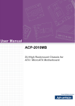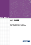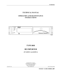
1
User Manual
IPC-603MB
Ultra Compact
2U Rackmount IPC Chassis
with Front I/O Interfaces
Copyright
The documentation and the software included with this product are copyrighted 2009
by Advantech Co., Ltd. All rights are reserved. Advantech Co., Ltd. reserves the right
to make improvements in the products described in this manual at any time without
notice.
No part of this manual may be reproduced, copied, translated or transmitted in any
form or by any means without the prior written permission of Advantech Co., Ltd.
Information provided in this manual is intended to be accurate and reliable. However,
Advantech Co., Ltd. assumes no responsibility for its use, nor for any infringements
of the rights of third parties, which may result from its use.
Acknowledgements
The IPC-603MB, AIMB-742, AIMB-744, AIMB-750, AIMB-760, AIMB-762, AIMB-763,
AIMB-764 and AIMB-560 are all trademarks of Advantech Co., Ltd.
All other product names or trademarks are properties of their respective owners.
On-line Technical Support
For technical support and service, please visit our support website at:
http://www.advantech.com/support
IPC-603MB User Manual
Part No. 2002060301
Edition 2
Printed in China
June 2009
ii
Safety Instructions
1.
2.
3.
4.
5.
6.
7.
8.
9.
10.
11.
12.
13.
14.
15.
16.
17.
Read these safety instructions carefully.
Keep this user manual for later reference.
Disconnect this equipment from AC outlet before cleaning. Do not use liquid or
spray detergents for cleaning.
For pluggable equipment, the power outlet shall be installed near the equipment
and shall be easily accessible.
Keep this equipment away from humidity.
Put this equipment on a reliable surface during installation. Dropping it or letting
it fall could cause damage.
Do not leave this equipment in an environment unconditioned where the storage
temperature under 0°C (32°F) or above 40°C (104°F), it may damage the equipment.
The openings on the enclosure are for air convection hence protects the equipment from overheating. DO NOT COVER THE OPENINGS.
Make sure the voltage of the power source is correct before connecting the
equipment to the power outlet.
Place the power cord such a way that people can not step on it. Do not place
anything over the power cord. The voltage and current rating of the cord should
be greater than the voltage and current rating marked on the product.
All cautions and warnings on the equipment should be noted.
If the equipment is not used for long time, disconnect it from the power source to
avoid being damaged by transient over-voltage.
Never pour any liquid into ventilation openings. This could cause fire or electrical shock.
Never open the equipment. For safety reasons, the equipment should be
opened only by qualified service personnel.
If any of the following situations arises, get the equipment checked by service
personnel:
a)
The power cord or plug is damaged.
b)
Liquid has penetrated into the equipment.
c)
The equipment has been exposed to moisture.
d)
The equipment does not work well or you cannot get it to work according to the user manual.
e)
The equipment has been dropped and damaged.
f)
The equipment has obvious signs of breakage.
CAUTION: The computer is provided with a battery-powered real-time clock circuit. There is a danger of explosion if battery is incorrectly replaced. Replace
only with same or equivalent type recommended by the manufacture. Discard
used batteries according to the manufacturer’s instructions.
THE COMPUTER IS PROVIDED WITH CD DRIVES COMPLY WITH APPROPRIATE SAFETY STANDARDS INCLUDING IEC 60825.
CLASS 1 LASER PRODUCT
KLASSE 1 LASER PRODUKT
iii
IPC-603MB User Manual
18. This device complies with Part 15 of the FCC rules. Operation is subject to the
following two conditions:
1) This device may not cause harmful interference, and
2) This device must accept any interference received, including interference that
may cause undesired operation.
19. CAUTION: Always completely disconnect the power cord from your chassis
whenever you work with the hardware. Do not make connections while the
power is on. Sensitive electronic components can be damaged by sudden
power surges.
20. CAUTION: Always ground yourself to remove any static charge before touching
the motherboard, backplane, or add-on cards. Modern electronic devices are
very sensitive to static electric charges. As a safety precaution, use a grounding
wrist strap at all times. Place all electronic components on a static-dissipative
surface or in a static-shielded bag when they are not in the chassis.
21. CAUTION: Any unverified component could cause unexpected damage. To
ensure the correct installation, please always use the components (ex. screws)
provided with the accessory box.
A Message to the Customer
Advantech Customer Services
Each and every Advantech product is built to the most exacting specifications to
ensure reliable performance in the harsh and demanding conditions typical of industrial environments. Whether your new Advantech equipment is destined for the laboratory or the factory floor, you can be assured that your product will provide the
reliability and ease of operation for which the name Advantech has come to be
known. Your satisfaction is our primary concern. Here is a guide to Advantech's customer services.
To ensure you get the full benefit of our services, please follow the instructions below
carefully.
Technical support
We want you to get the maximum performance from your products. So, if you run into
technical difficulties, we are here to help. For the most frequently asked questions,
you can easily find answers in your product documentation. These answers are normally a lot more detailed than the ones we can give over the phone.
Please consult this manual first. If you still cannot find the gather all the information or
answer questions that apply to your problem, please call your dealer. Please make
sure you have the product close at hand. Our dealers are well trained and ready to
give you the support you need to get the most from your Advantech products. In fact,
most problems reported are minor and are easily solved over the phone.
In addition, free technical support is available from Advantech engineers every business day. We are always ready to give advice on application requirements or specific
information on the installation and operation of any of our products.
IPC-603MB User Manual
iv
Product Warranty (2 years)
Advantech warrants to you, the original purchaser, that each of its products will be
free from defects in materials and workmanship for two years from the date of purchase.
This warranty does not apply to any products which have been repaired or altered by
persons other than repair personnel authorized by Advantech, or which have been
subject to misuse, abuse, accident or improper installation. Advantech assumes no
liability under the terms of this warranty as a consequence of such events.
Because of Advantech’s high quality-control standards and rigorous testing, most of
our customers never need to use our repair service. If an Advantech product is defective, it will be repaired or replaced at no charge during the warranty period. For outof-warranty repairs, you will be billed according to the cost of replacement materials,
service time and freight. Please consult your dealer for more details.
If you think you have a defective product, follow these steps:
1. Collect all the information about the problem encountered. (For example, CPU
speed, Advantech products used, other hardware and software used, etc.) Note
anything abnormal and list any onscreen messages you get when the problem
occurs.
2. Call your dealer and describe the problem. Please have your manual, product,
and any helpful information readily available.
3. If your product is diagnosed as defective, obtain an RMA (return merchandise
authorization) number from your dealer. This allows us to process your return
more quickly.
4. Carefully pack the defective product, a fully-completed Repair and Replacement
Order Card and a photocopy proof of purchase date (such as your sales receipt)
in a shippable container. A product returned without proof of the purchase date
is not eligible for warranty service.
5. Write the RMA number visibly on the outside of the package and ship it prepaid
to your dealer.
v
IPC-603MB User Manual
Initial Inspection
When you open the carton, please make sure that the following materials have been
shipped:
! Chassis
! User Manual
! Warranty Card
! Accessory box with a package of screws (for fastening the disk drives, motherboard, ears and handles, etc.), a plastic post, and a pair of ears and handles.
If any of these items are missing or damaged, contact your distributor or sales representative immediately. We have carefully inspected the IPC-603 mechanically and
electrically before shipment. It should be free of marks and scratches and in perfect
working order upon receipt. As you unpack the IPC-603, check it for signs of shipping
damage. (For example, damaged box, scratches, dents, etc.) If it is damaged or it
fails to meet the specifications, notify our service department or your local sales representative immediately. Also notify the carrier. Retain the shipping carton and packing material for inspection by the carrier. After inspection, we will make arrangements
to repair or replace the unit.
IPC-603MB User Manual
vi
Contents
Chapter
1
General Information ............................1
1.1
1.2
1.3
Introduction ............................................................................................... 2
Specifications ............................................................................................ 2
Environmental Specifications .................................................................... 2
Table 1.1: Environmental Specifications ..................................... 2
Power Supply Options............................................................................... 2
Table 1.2: Power Supply Options ................................................ 2
Dimension Diagram................................................................................... 3
Figure 1.1 Dimension Diagram .................................................... 3
1.4
1.5
Chapter
2
System Setup .......................................5
2.1
Removing the Top Cover .......................................................................... 6
Figure 2.1 Removing the top cover............................................. 6
Installing a Motherboard............................................................................ 7
Figure 2.2 Placing a spacer bracket ............................................ 7
Installing a Riser Card and Add-on Cards................................................. 8
Installing Disk Drives................................................................................. 8
Figure 2.3 Install a slim ODD and a HDD .................................... 8
Figure 2.4 Place the drive bay bracket kit into the chassis.......... 9
Attaching the Ears & Handles ................................................................... 9
Figure 2.5 Attaching the ears and handles .................................. 9
2.2
2.3
2.4
2.5
Chapter
3
Operation............................................11
3.1
The Front Panel ...................................................................................... 12
3.1.1 Switch and button ....................................................................... 12
3.1.2 LED indicators............................................................................. 12
Table 3.1: System Status LED Summary .................................. 12
Replacing the Fans ................................................................................. 12
Figure 3.1 Replacing the fans.................................................... 12
Replacing the filters................................................................................. 13
Figure 3.2 Replacing the filters ................................................. 13
Replacing the power supply .................................................................... 13
Figure 3.3 Replacing the power supply ..................................... 13
3.2
3.3
3.4
Appendix A
Exploded Diagram .............................15
A.1
Exploded Diagram................................................................................... 16
Figure A.1 Exploded Diagram .................................................... 16
Appendix B
Motherboard & Riser Card Options .17
B.1
Motherboard Options .............................................................................. 18
Table B.1: ATX motherboard options......................................... 18
Table B.2: MicroATX motherboard options................................ 18
Riser Card Options.................................................................................. 19
Table B.3: Riser card options..................................................... 19
B.2
vii
IPC-603MB User Manual
IPC-603MB User Manual
viii
Chapter
1
1
General Information
This chapter provides general
information about the IPC-603MB.
Sections include:
! Introduction
! Specifications
! Power supply options
! Environment specification
! Dimensions
1.1 Introduction
IPC-603MB is an ultra compact 2U-high rackmount industrial computer chassis
designed for space-conscious applications. With only 310 mm depth, IPC-603MB
can accept any of Advantech ATX/mATX motherboards, and up to three half-sized
add-in cards with the supported riser card.
1.2 Specifications
!
!
!
!
!
!
!
!
Construction: Heavy-duty steel
Disk drive capacity: one slim-type CD-ROM and one internal HDD
Indicators on front panel: LEDs for Power and HDD
Switches on front panel: Power and Reset
Cooling fans: dual 47 CFM
Air filters: three 85 x 80 mm filters on the rear plate
Weight: 6.4 kg (14.1 lb)
Dimensions (W x H x D): 482 x 88 x 310 mm (19" x 3.46" x 12.2")
1.3 Environmental Specifications
Table 1.1: Environmental Specifications
Environment
Operating
Non-operating
Temperature
0 to 40°C (32 to 104°F)
-20 to 60°C (-4 to 140°F)
Humidity
10 to 95% @ 40°C, non-condensing
Vibration (5~500 MHz)
1 Grms
2G
Shock
10 G with 11 ms duration, half
sine wave)
30 G 11 ms duration
Altitude
0 to 3,048 m (0 ~ 10,000ft)
Safety
CE compliant
1.4 Power Supply Options
Table 1.2: Power Supply Options
Model Name
1757000160 (ATX, PFC)
Watts
300 W max.
Input rating
100 ~ 240 Vac @ 50~60 Hz (Full range)
Output voltage
+5 V @ 25 A, +3.3 V @ 14 A,
+12 V @ 16 A, -12 V @ 1 A,
-5 V @ 0.5 A, +5 Vsb @ 1.5 A (peak 2 A)
Minimum load
+5 V @ 3 A, +12 V @ 2 A,
-5 V @ 0.05 A, -12 V @ 0.05A,
+3.3 V @ 1 A, +5 Vsb @ 0.1 A
MTBF
100,000 hours @ 25° C
Safety
UL/TUV/CB/CCC
IPC-603MB User Manual
2
Chapter 1
1.5 Dimension Diagram
General Information
Figure 1.1 Dimension Diagram
3
IPC-603MB User Manual
IPC-603MB User Manual
4
Chapter
2
2
System Setup
This chapter introduces the installation process.
Sections include:
! Installing the motherboard
! Installing a riser card and addon card
! Installing disk drives
! Attaching the ears and handles
The following procedures are provided to assist you in installing a motherboard,
drives, and add-on cards into the chassis. Refer to Appendix A, Exploded Diagram,
for all the detailed parts.
2.1 Removing the Top Cover
To remove the top cover of IPC-603MB, please refer to Figure 2.1.
Figure 2.1 Removing the top cover
IPC-603MB User Manual
6
IPC-603MB accepts both ATX and microATX motherboards. To install a motherboard, please proceed as follows:
Note!
3.
Remove the three screws from the L-form riser card holder in the chassis.
From inside of the chassis, attach the motherboard I/O shield to the front plate
of the chassis.
Check all devices, such as CPU, CPU cooler, and RAMs and make sure they
have been installed on the motherboard correctly. Carefully place the motherboard in the chassis and fix it with screws.
Note!
If you choose Advantech’s AIMB-740, 741, 742, or 76X ATX motherboard, please find a spacer bracket in the accessory bag and mount it
on location A in the bottom of the chassis before installing the motherboard.
If you choose Advantech’s AIMB-5XX series of microATX motherboard,
please find a spacer bracket in the accessory bag and mount it on location B in the bottom of the chassis before installing the motherboard.
Figure 2.2 Placing a spacer bracket
4.
5.
6.
7.
Plug in the 24- or 20-pin ATX power connector and the +12 V power connector
from the power supply.
Connect the Power switch, Reset button, Power LED, and HDD LED wires to
the motherboard.
Connect the power connectors of the two system fans (on the rear plate of IPC603MB) to the motherboard.
Re-install the L-form riser card holder and fasten it with screws.
7
IPC-603MB User Manual
System Setup
1.
2.
Use a CPU cooler that is less than 60 mm high to ensure the best air
flow inside the chassis.
Chapter 2
2.2 Installing a Motherboard
2.3 Installing a Riser Card and Add-on Cards
The IPC-603MB can accept up to three half-sized PCI add-on cards via the riser
card. To install a riser card and add-on card, face to the rear side of the chassis and
proceed as follows:
1.
Insert the riser card to the 6th slot of the ATX motherboard or the 3rd slot of the
microATX motherboard.
2. Remove the I/O bracket attached to the rear plate of the chassis.
3. Horizontally and evenly push the card leftward until the gold fingers are completely inserted into a PCI slot of the riser card. Make sure that the card bracket
has been inserted properly. Fasten the card at the top of I/O the bracket with a
screw.
4. Repeat step 2 and 3 if there is more than one card.
2.4 Installing Disk Drives
The IPC-603MB accepts one slim type ODD and one internal 3.5” SATA/ATA HDD.
To install the disk drives, refer to Figures 2.3 and 2.4 and proceed as follows:
HDD
Slim
CD-ROM
Figure 2.3 Install a slim ODD and a HDD
IPC-603MB User Manual
8
Chapter 2
HDD
Slim
CD-ROM
1.
2.
3.
4.
5.
6.
Open the top cover of the chassis.
Remove the four screws that mount the drive bay bracket kit in the chassis.
Remove the front cover of the slim-type ODD from the bracket kit.
Refer to Figure 2.4 and mount a slim-type ODD and a 3.5" HDD with screws.
Return the drive bay bracket kit into the chassis and fix it with screws.
Connect a 40-pin flat cable from the motherboard to the slim-type ODD, and
another 40-pin flat cable to an ATA (IDE) HDD or a SATA cable to a SATA HDD.
Insert the proper power connectors into each drive.
2.5 Attaching the Ears & Handles
The IPC-603MB provides a pair of ears and handles in the accessory pack. To install
the ears and handles onto the chassis, refer to Figure 2.5.
rackmount bracket
rackmount bracket
handle
handle
Figure 2.5 Attaching the ears and handles
9
IPC-603MB User Manual
System Setup
Figure 2.4 Place the drive bay bracket kit into the chassis
IPC-603MB User Manual
10
Chapter
3
3
Operation
This chapter introduce the system
operating information.
Sections include:
! The Front Panel
! Replacing the Cooling Fan
! Replacing the Filter
! Replacing the Power
3.1 The Front Panel
3.1.1 Switch and button
There is a power switch and a system reset button on the front panel. Press the System Reset button to reinitialize the system. Press the Power On-Off Switch to turn the
system power on or off.
3.1.2 LED indicators
Two LEDs indicate the system status. Refer to Table 3.1 for the LED summary.
Table 3.1: System Status LED Summary
LED
Description
Green/Orange
PWR
System Power
Normal
HDD
Hard Drive Disk Activity
Data Access
When the system power is on, the power LED is always Green.
3.2 Replacing the Fans
There are two fans on the rear plate of the chassis. To change any failed fan, refer to
Figure 3.1 and proceed as follows:
1. Open the top cover of the chassis.
2. Unplug the power connector of a failed fan from the motherboard and the fan filter behind the failed fan.
3. Remove the four screws, which mount the failed fan to the chassis and lift it with
two fingers.
4. Place a new fan on the proper location, and fasten it with four screws.
5. Return the fan filter and plug in the fan power connector.
6. Repeat Steps 3 ~ 5 if you want to change the other fan.
f
f
filter
filter
Figure 3.1 Replacing the fans
IPC-603MB User Manual
12
To change the filters, refer to Figure 3.2 and proceed as follows:
1. Open the top cover of the chassis.
2. Pull out the filters and replace it with a new one.
filter
filter
Chapter 3
3.3 Replacing the filters
filter
Operation
Figure 3.2 Replacing the filters
3.4 Replacing the power supply
IPC-603MB supports a single 1U-high power supply. To replace the power supply,
refer to Figure 3.3 and proceed as follows:
Floppy Drive Power Connector
+12V Power Connector
Peripheral Power Connector
ATX Power Connector
Figure 3.3 Replacing the power supply
1.
2.
3.
Unplug the power cord from the power supply.
Remove the top cover of the chassis.
Unplug the ATX power connector and +12 V power connector from the motherboard, and the peripheral power connector(s) from the disk(s).
13
IPC-603MB User Manual
4.
5.
6.
7.
8.
9.
Refer to Figure 3.3 to remove the drive bay.
Remove the six screws which mount the power supply to the chassis, then lift
the power supply.
Place a new power supply into the chassis and fasten it with the screws.
Return the drive bay to the chassis.
Plug the ATX power connector and +12V power connector into the motherboard, and the peripheral power connector(s) into the proper disk(s).
Replace the top cover and plug in the power cord.
IPC-603MB User Manual
14
Appendix
A
A
Exploded Diagram
A.1 Exploded Diagram
Figure A.1 Exploded Diagram
IPC-603MB User Manual
16
Appendix
B
B
Motherboard &
Riser Card Options
B.1 Motherboard Options
The IPC-603MB supports a variety of Advantech ATX/MicroATX motherboards
described below. Contact a local sales representative for more detailed information.
Table B.1: ATX motherboard options
Model Name
Bus
PCI
PCI/ISA
ISA
AGP
SATA
AIMB-764
1 (PCIe x16)
1 (PCIe x4)
5 (PCI 32-bit)
-
-
-
5
AIMB-763
1 (PCIe x 16)
1 (PCIe x 1)
5 (PCI 32-bit)
-
-
-
4
AIMB-762
1 (PCIe x16)
1 (PCIe x4)
5 (PCI 32-bit)
-
-
-
4
AIMB-750
2 (PCI-X 64-bit)
4 (PCI 32-bit)
-
-
1 (4X)
2
AIMB-744
2 (PCI-X 64-bit)
4 (PCI 32-bit)
-
-
1 (8X)
2
AIMB-742
(32-bit)
1
1
1 (8X)
-
Table B.2: MicroATX motherboard options
Model Name
Bus
PCI
SATA
AIMB-566
1 (PCIe x4)
1 (PCI 32-bit)
6
AIMB-564
1 (PCIe x16)
1 (PCIe x4)
2 (PCI 32-bit)
7
AIMB-562 KIOSK
1 (PCIe x1)
2 (PCI 32-bit)
2
AIMB-556
1 (PCIe x16)
1 (PCIe x4)
2 (PCI 32-bit)
3
AIMB-554
1 (PCIe x16)
1 (PCIe x4)
2 (PCI 32-bit)
2
AIMB-552
3 (PCI 32-bit)
2
IPC-603MB User Manual
18
The riser card is specially designed to support Advantech AIMB series of motherboards.
Table B.3: Riser card options
Model Name Interface
AIMB-R4301
PCIe x4
AIMB-R430P PCIe x4
Expansion Slots
Compatible
Motherboards
3 PCIe x1
AIMB-764/762/556/554
3 PCI
AIMB-764/762/556/554
AIMB-R431F PCIe x 16 + PCIe x 4 1 PCIe x 16 + 2 PCIe x 1 AIMB-764/762/556/554
AIMB-RP30P PCI
3 PCI
AIMB-RP3PF PCIe x 16 + PCI
1 PCIe x 16 +2 PCI
AIMB-R43PF PCIe x 16 + PCIe x 4 1 PCIe x 16 + 2 PCI
19
AIMB-766/750/744/742/
740/566/564/552/542
AIMB-763/564/562
AIMB-764/762/556/554
IPC-603MB User Manual
Appendix B Motherboard & Riser Card Options
B.2 Riser Card Options
www.advantech.com
Please verify specifications before quoting. This guide is intended for reference
purposes only.
All product specifications are subject to change without notice.
No part of this publication may be reproduced in any form or by any means,
electronic, photocopying, recording or otherwise, without prior written permission of the publisher.
All brand and product names are trademarks or registered trademarks of their
respective companies.
© Advantech Co., Ltd. 2009