1
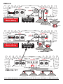
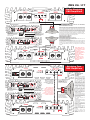
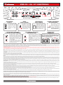
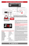
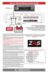
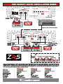
ZRS C5
1-Ohm Mono Load
Woofer Wiring
Remote turn on
from radio, do not
wire woofers to
this terminal!
= 1-Ohm Load.
2-Ohm
Final Woofer Load
Or
2-Ohm
Final Woofer Load
DVC 2-Ohm
Wired in Parallel
to 1-Ohm
To amp +
1-Ohm Mono Load
Woofer Wiring
To amp -
Remote turn on
from radio, do not
wire woofers to
this terminal!
DVC 4-Ohm
Wired in Parallel
to 2-Ohm
DVC 4-Ohm
Wired in Parallel
to 2-Ohm
= 1-Ohm Load.
ZRS C6 / C7
4-Ohm
Subwoofer
4-Ohm
Subwoofer
4-Ohm
Subwoofer
4-Ohm
Subwoofer
Four 4-Ohm Subwoofers wired in parallel to the C5, C6 or C7 will equal a 1-Ohm mono load.
ZRS C6 / C7
Daisy Chaining
ZRS Amplifiers
DAISY CHAINING AMPLIFIERS, HOW TO SET SWITCHES,
INPUTS AND REMOTE CONTROL.
1-Ohm
Final Impedance
Load!
RCA Headunit signal to
Master Amp only! No RCA
Cables to be attached to
Slave Amplifier.
Amp #1 in Master Mode Fully adjusted Signal
is transferred from
Master to Slave Amp
Amp #2 in Slave Mode
via RCA Cable.
When daisy chaining two amplifiers together all pre amp signals including
crossover, phase control, bass equalizer, input gain, subsonic filter, bass
focus are controlled by the Master amplifier. The entire pre amp section of the
Slave amplifier is bypassed. This is done so all you have to do is to set the
Master amplifier and the Slave amplifier will match the Master exactly. There
is no need for any manual matching to occur. This ensures perfect alignment
of your system. One Bass Control knob, plugged in to the Master amplifier
will also control both amplifiers, thereby simplifying your installation as well.
Use the RCA Pre amp Output of the Master Amplifier to feed secondary Full
Range Multi-Channel amplifiers for a Mult-Amp system.
Set Master Amplifier to “MASTER”
Set Salve amplifier to “SLAVE”
1-Ohm
Final Impedance
Load!
Set Phase Shift on both amps to same position.
Set all crossover setting, bass equalizer, subsonic filter, bass focus on
MASTER amp to desired settings.
Use a standard RCA cable to connect MASTER OUT of amplifier #1 (Master)
to SLAVE IN of amplifiers #2 (SLAVE).
Connect woofers as you would typically connect them to each amplifier, not
exceeding a 1 ohm load per amplifier. You can daisy chain as many ZRS C1
as you like while retaining control of your entire system from the Master
amplifier.
.When
daisy chaining
2 ZRS amplifiers, you
can wire each woofer
to any of the
amplifiers positive or
negative terminals as
they are wired
internally in parallel.
Under no
circumstances can
you daisy chain two
different models of
amplifiers.
Bridging Two
ZRS Amplifiers
BRIDGING AMPLIFIERS
HOW TO SET
SWITCHES, INPUTS
AND REMOTE
CONTROL.
RCA Headunit signal to
Master Amp only! No RCA
Cables to be attached to
Slave Amplifier.
MINUS TERMINAL OF
WOOFER TO
MASTER AMPLIFIER
POSITIVE TERMINAL.
2-Ohm
Final Impedance
Load!
USE HEAVY GAUGE
WIRE TO CONNECT
BOTH AMPLIFIERS
SPEAKER “NEGATIVE”
CONNECTIONS.
When bridging two
Amp #1 in Master Mode Fully adjusted Signal
ZRS C amplifiers, the
is transferred from
final impedance of the
Master to Slave Amp bridged channel shall be
Amp #2 in Slave Mode
via RCA Cable.
no less than 2 ohms.
Under no circumstances
can you bridge two different
models of amplifiers
POSITIVE TERMINAL
OF WOOFER TO
SLAVE AMPLIFIER
POSITIVE TERMINAL.
When bridging two amplifiers
together all pre amp signals
including crossover, phase
control, bass equalizer, input
gain, subsonic filter, bass
focus are controlled by the
Master amplifier. The entire
pre amp section of the Slave
amplifier is bypassed. This is
done so all you have to do is to
set the Master amplifier and
the Slave amplifier will match
the Master exactly. There is
no need for any manual
matching to occur. This
ensures perfect alignment of
your system. One Bass
Control knob, plugged in to
the Master amplifier will also
control both amplifiers,
thereby simplifying your
installation as well.
You can use the RCA Pre amp
Output of the Master Amplifier
to feed secondary Full Range
Multi-Channel amplifiers for a
Mult-Amp system.
Set Master Amplifier to
“MASTER”
Set Salve amplifier to SLAVE.
Set Phase Shift on both amps
to same position.
Set all crossover setting, bass
equalizer, subsonic filter,
bass focus on MASTER amp
to desired settings.
Usea standard RCA cable to
connect MASTER OUT of
amplifier #1 (Master) to
SLAVE IN of amplifiers #2
(SLAVE).
C o nne ct a h e avy duty
speaker wire between the
NEGATIVE terminals of both
amplifiers.
ZRS C5 / C6 / C7 CONTROLS
RCA PREAMP
OUTPUT
INPUT
GAIN CONTROL
The preamp output is a
full range signal mixed
from both input
channels. Use this
signal to feed a
secondary full range
amplifier
in your
system.
ADJUSTABLE SUBSONIC
FILTER WITH PHASE CONTROL
The ZRS C5,6,7 feature a fully
adjustable Subsonic Filter which can
be set from 10Hz - 50Hz. This High
Pass Filter is especially useful when
tuning vented enclosures. The
Subsonic filter should be set at vent
tuning frequency to protect against
woofer unloading.
The adjustable Phase Control will
help fine tune your bass system to
time align with your midrange and
high frequency speakers.
DASH MOUNT
BASS REMOTE
The ZRS C5, C6, and
amplifiers features
advanced input gain
control from 0.2 volts to 6
volts so that the amp can
operate efficiently and at
full power from any head
unit pre amp signal.
When using the Remote
Subwoofer Control in a
multi amp system the
bass remote of the Master
amp will control all amps
in the system. Use only
cable supplied with the
remote for connection.
ZRS amplifiers feature
sophisticated IC
controlled protection
circuitry. If the amp goes
in to a diagnostic
condition from thermal
over load or speaker short
circuit the LED will light
and amp will shut down.
CONNECTION
TERMINALS
24dB CROSSOVER SLOPE
BASS EQUALIZER
The crossover of the ZRS C5,6,7
features a steep 24dB per octave
slope Linkwitz-Riley low pass
crossover ensuring that only the
lowest frequencies are reproduced by
the amplifier.
POWER & DIAGNOSTIC
LED INDICATORS
The ZRS C5, C6, C7 features heavy duty bolt down
terminals, the power and ground terminals accept 0 - 2
gauge wire while the speaker terminals can accept 8
gauge wire. BE SURE TO HOOK-UP BOTH POWER
TERMINALS ON THE C6 AND C7.
The amplifier also includes a Bass
Equalizer with a center frequency of
45Hz which can be adjusted for up to
9dB of additional gain at that
frequency.
We have spared no expense in designing these amplifiers, creating the most rugged, reliable, powerful and best performing amplifiers. In fact we are so sure of the quality we backup every ZRS Series amplifier
with our exclusive two-year warranty which exemplifies our commitment to excellence in car audio musical reproduction. (See enclosed warranty card for details.)
Please read this installation guide carefully for proper use of your Cadence power amplifier. Should you need technical assistance during or after your installation please call our technical-line between 9:30 am
and 5:00 PM EST at 732/370-5400. Read this entire guide fully before attempting your installation.
WARNING: BE AWARE! Use of this amplifier at extreme high volumes for extended periods of time may cause hearing loss and or hearing damage. During periods of prolonged high volume levels it is
recommended that you use ear safety devices. Playing Cadence amplifiers at high volume levels while driving will impair your ability to hear necessary traffic sounds. While driving always keep your sound
volume at reasonable levels. We at Cadence want you listening for many years to come.
When installing the amplifier, secure it tightly. An unmounted amplifier in your car can cause serious injury to passengers and damage to your vehicle if it is set in motion by an abrupt driving maneuver or short
stop.
We suggest you construct a Red wiring harness with 2 additional fuse. One fuse should be located near the car battery. This fuse near the battery offers protection against damage from short circuits to the car
chassis between the battery and the amplifier. A second fuse closer to the amplifier offers additional safety to the amplifier itself. This fused red power wire should be attached to the amplifier power terminal
marked 12V+.
The wire harness should be made of primary cable of at least 4 gauge. The harness should terminate in a large ring terminal for connection directly to the positive terminal of the car battery. Use a spade plug to
attach the wire, which connects to the amplifier location marked 12V+.
A second black color wire of equal gauge should be used as a ground connection to a welded chassis member. When connecting the ground wire make sure that there is no paint or other insulator blocking a good
ground connection. When installing multiple amplifiers, mount them in close proximity so that they can all share the same ground point. Attach the black ground wire to the amplifier screw terminal marked
Ground.
We recommend that you use the Cadence amplifier installation kits, which contain all the cabling and accessories necessary for a good, reliable installation.
Over the years we have received amplifiers back to our service department with melted power/ground terminals. The cause of this is a bad ground connection. When there is a lack of good ground, heat builds up
at the weakest point which happens to be the contact screw of the amplifier terminal. Over time the heat generated will begin to melt the terminal. It is a good practice to feel the power and ground wires with your
hands, near their amplifier connection after having played the amp for a while. If the wires feel hot to the touch you probably have a bad or loose connection. If you are sure of your connections and the wires still
feel hot to the touch, you should upgrade the gauge of wire to next heaviest gauge.
The remote turn on connection is located on the barrier strip next to the power and ground connections. This connection is responsible for turning the amplifier on and off with the rest of the system. A smaller
gauge wire can be used to make this connection to your radio's power antenna lead. Should your system not have any turn on leads, you can wire the remote terminal to an accessory lead, which turns on, with
your cars ignition.
The ZRS Series amplifiers feature RCA preamp inputs. Run RCA cables from your sound source to the inputs of the amplifier. We suggest the use of high quality shielded RCA patch cords to help reduce and
eliminate unwanted electrical noise to your system.
To avoid electrical noise from being injected in to your sound systems be sure to run the RCA cables on the opposite side of the vehicle that you used to carry the power and ground leads of the amplifier.
Before you begin with your installation, disconnect the NEGATIVE (-) terminal from your car's battery. This safety precaution will avoid possible short circuits while wiring your amplifier. Cadence amplifiers
operate on 12-volt negative ground systems only.
It is recommend that you layout your sound system design on paper first. This will help you during the installation so that you will have a wiring flow chart and not miss-wire any of your components.
Mount the amplifier in the trunk or hatch area of your vehicle. Never install an amplifier in the engine compartment or on the firewall. Please be sure to leave breathing room around the amplifier heat sink so that it
can dissipate the heat it produces efficiently. The amplifier can be installed either horizontally or vertically.
When mounting the amplifier on the trunk floor, be sure to watch for your gas tank, gas lines and electrical lines. Do not drill or mount any screws where they might penetrate the gas tank of your car.
Once the system is operational, the first thing to do, is set all crossover points to approximate settings. In the case of the basic sub woofer system Low Pass filter crossover at 100 Hz or so. Set the Bass Boost
equalizer controls to 0 dB ( Flat Switch Position.)
Now you should set the amplifiers Input Sensitivity adjustment. The knob accessible on the side of the amplifier marked INPUT GAIN adjusts the input sensitivity from 300mV to 7Volts.
To adjust the input sensitivity, turn the control using a small flat head screwdriver fully counter clock wise to the minimum position. Do not apply any pressure while turning as this might break the control unit. Adjust
your radio volume level to maximum volume. Now turn the level control on the amplifier clockwise towards the Maximum marking until audible distortion occurs. When you begin to hear any distortion in the sound,
back down one notch and your amp is set. It is helpful to have a second person to help you set the gain.
When setting up a multi-amp system, set each amplifier’s gain separately. Start off with the bass amplifier, then adjust the highs amplifier’s level control to match.
Once you are satisfied with the level control settings, use any equalizer controls to adjust the system tonal level for personal preference. Keep in mind that after equalizing, you may have to go back and reset the
amplifiers level controls.
The level control of any car amplifier should not be mistaken for a volume control. It is a sophisticated device designed to match the output level of your source unit to the input level of the
amplifier. Do not adjust the amplifier gain to maximum unless your input level requires it.
If your unit has been professionally installed please do not change the gain settings set by the installer, he is the professional!
Your system can also be extremely sensitive to noise when the LEVEL is set to maximum and does not match your input signal. The gain adjustments need to be made only once when first setting up the system.