1
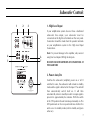
MS309W Subwoofer
Owners’ Manual
Introduction
Contents
Congratulations on purchasing this Mordaunt-Short
subwoofer. To ensure optimum performance please
read and retain this manual, then sit back, relax and
enjoy!
Introduction ......................................................................3
Safety Precautions ............................................................4
Subwoofer Controls .........................................................7
Attaching Feet to Your Subwoofer .................................9
Please read and retain this manual, it contains useful
information that will ensure you get the very best from
your new loudspeakers.
Note: This model is supplied in two mains voltage ratings.
Please refer to product rear panel for rating.
Running In.........................................................................9
Connecting Your Subwoofer ...........................................9
Getting The Most From Your Subwoofer ....................10
Taking Care of Your Subwoofer ...................................12
Technical Specifications ................................................13
Limited Warranty ...........................................................14
3
Important Safety Precautions
For safety reasons please read the following instructions and the enclosed
Important Safety Information carefully before attempting to connect your
subwoofer unit to the mains.
Warning
To reduce the risk of fire or electric shock, do not expose this appliance to
rain or moisture.
Caution
Use of controls or adjustments or performance of procedures other than
those specified may result in hazardous radiation exposure.
Caution
To reduce the risk of electric shock, do not remove cover (or back). There
are no user-serviceable parts inside. Please refer all servicing to a qualified
engineer.
The lightning flash with the arrowhead symbol within an
equilateral triangle is intended to alert the user to the
presence of uninsulated ‘dangerous voltage’ within the
product’s enclosure that may be of sufficient magnitude to
constitute a risk of electric shock to persons.
The exclamation point within an equilateral triangle is
intended to alert the user to the presence of important
operating and maintenance (servicing) instructions in the
literature accompanying the appliance.
This product complies with European Low Voltage
(73/23/EEC)
and
Electromagnetic
Compatibility
(89/336/EEC) Directives when used according to this
instruction manual.
4
Plug Fitting Instructions (UK only)
The cord supplied with this appliance is factory fitted with a 13A mains plug
fitted with a 3A fuse inside. If it is necessary to change the fuse, it is
important that a 3A one is used. If the plug needs to be changed because it
is not suitable for your socket, or becomes damaged, it should be cut off and
an appropriate plug fitted following the wiring instructions below. The plug
must then be disposed of safely, as insertion into a 13A socket is likely to
cause an electrical hazard. Should it be necessary to fit a 3-pin BS mains plug
to the power cord the wires should be fitted as shown in this diagram. The
colours of the wires in the mains lead of this appliance may not correspond
with the coloured markings identifying the terminals in your plug. Connect
them as follows:
wire which is coloured BLUE must
• The
be connected to the terminal which is
marked with the letter ‘N’ or coloured
BLACK
wire which is coloured BROWN
• The
must be connected to the terminal
which is marked with the letter ‘L’ or
coloured RED
wire which is coloured GREEN/
• The
YELLOW must be connected to the
terminal which is marked with the
letter ‘E’ or coloured GREEN.
Note
If a 13 Amp (BS 1363) type of plug is used a 3 Amp or 5 Amp fuse must be
fitted, either in the plug or adaptor, or on the distribution board.
Important Safety Precautions
Read Instructions
All the safety and operating instructions should be read before the product
is operated
A product and stand combination should be moved with care. Quick stops,
excessive force, and uneven surfaces may cause the combination to
overturn.
Retain Instructions
The safety and operating instructions should be retained for future
reference.
Heed Warnings
All warnings on the product and the operating instructions should be
adhered to.
Follow instructions
All operating and use instructions should be followed.
Cleaning
Unplug this product from the wall outlet before cleaning. Do not use liquid
cleaners or aerosol cleaners. Use a damp cloth for cleaning.
Attachments
Do not use attachments not recommended by the product manufacturer as
they may cause hazards.
Ventilation
Slots and openings in the cabinet are provided for ventilation and to ensure
reliable operation of the product and to protect it from overheating, and
these openings must not be blocked or covered. The openings should never
be blocked by placing the product on a bed, sofa, rug, or other similar
surface. This product should not be placed in a built-in installation such as a
bookcase or rack unless proper ventilation is provided or the manufacturer's
instructions have been adhered to.
Power Sources
Do not use this product near water - for example, near a bath tub, wash
bowl or kitchen sink; in a wet basement, or near a swimming pool etc.
This product should be operated only from the type of power source
indicated on the marking label. If you are not sure of the type of power
supply to your home, consult your product dealer or local power company.
For products intended to operate from battery power, or other sources, refer
to the operating instructions.
Accessories
Grounding or Polarization
Do not place this product on an unstable surface, stand, bracket or table.
The product may fall, causing serious injury to child or adult, and serious
damage to the product. Use only a surface, stand bracket or table
recommended by the manufacturer, or sold with the product. Any mounting
of the product should follow the manufacturer's instructions, and should use
a mounting accessory recommended by the manufacturer.
In some countries this product may be eqiupped with a polarized alternatingcurrent line plug (a plug having one pin wider than the other). This plug will
fit into the power outlet only one way. This is a safety feature. If you are
unable to insert the plug into the outlet, try reversing the plug. If the plug still
does not fit, contact your electrician to replace your obsolete outlet. Do not
defeat the safety purpose of the polarized plug.
Water and Moisture
5
Important Safety Precautions
Power-Cord Protection
Damage Requiring Service
Power supply cords should be routed so that they are not likely to be walked
on or pinched by items placed upon or against them, paying particular
attention to cords at plugs, convenience receptacles, and point where they
exit from the product.
Unplug this product from the wall outlet and refer servicing to qualified
service personnel under the following conditions:
a) When the power-supply cord or plug is damaged
b) If liquid has been spilled, or objects have fallen onto the product
c) If the product has been exposed to rain or water
d) If the product does not operate normally by following the operating
instructions. Adjust only those controls that are covered by the
operating instructions as an improper adjustment of other controls may
result in damage and will often require extensive work by a qualified
technician to restore the product to its normal operation
e) If the product has been dropped or damaged in any way
f) When the product exhibits a distinct change in performance - this
indicates a need for service.
Lightning
For added protection for this product during a lightning storm, or when it is
left unattended and unused for long periods of time, unplug it from the wall
outlet and disconnect the antenna or cable system. This will prevent damage
to the product due to lightning and power-line surges.
Overloading
Do not overload wall outlets, extension cords, or integral convenience
receptacles as this can result in a risk of fire or electric shock.
Object and Liquid Entry
Replacement Parts
Never push objects of any kind into this product through openings as they
may touch dangerous voltage points or short-out parts that could result in a
fire or electric shock. Never spill liquid of any kind on the product.
When replacement parts are required, be sure the service technician has
used replacement parts specified by the manufacturer or have the same
characteristics as the original part. Unauthorised substitutions may result in
fire, electric shock, or other hazards.
Servicing
Safety Checks
Do not attempt to service this product yourself as opening or removing
covers may expose you to dangerous voltage or other hazards. Refer all
servicing to qualified service personnel.
Upon completion of any service or repairs to this product, ask the service
technician to perform safety checks to determine that the product is in
proper operating condition.
Heat
The product should be situated away from heat sources such as radiators,
heat registers, stoves, or other products (including amplifiers) that produce
heat.
6
Subwoofer Controls
1
2
3
8
1. High Level Input
If your amplification system does not have a dedicated
subwoofer line output, your subwoofer must be
connected via the high level terminals on the rear panel.
Connection should be made from the speaker terminals
on your amplification system to the High Level Input
Connections.
10
6
12
4
14
2
16
4
6
7
5
Note: To prevent damage to the amplifier, only connect
using line level inputs OR high level inputs.
DO NOT USE BOTH METHODS OF CONNECTION AT
THE SAME TIME
340W
2. Power Auto/On
8
CAUTION
FOR CONTINUED PROTECTION AGAINST
FIRE HAZARD, REPLACE ONLY
WITH T2.5AL FUSE
ATTENTION
AFIN D'ASSURER UNE PRETECTION PERMANENTE
CONTRE LES RISQUES D'INCENDIE, REMPLACER UNIQUEMENT PAR UN
FUSIBLE DE MEME TYPE T2.5AL
Switches the subwoofer (amplifier) power on or off. If
switched to auto, the subwoofer will remain in standby
mode until a signal is detected at the input. The unit will
then automatically switch itself on. It will then
automatically return to standby mode if no input signal is
present for approximately five minutes. With the switch
in the 'ON' position the unit remains permanently on. The
LED positioned on the rear panel indicates whether the
unit is on or in standby mode (red for standby and green
when on).
7
Subwoofer Controls
3. Variable Notch Filter
6. Phase
For details on how to operate the Variable Notch Filter,
see Page 10.
This allows you to match the time integration of your
subwoofer to the other speakers in your system. This is
especially useful when the subwoofer and any other
speakers in your system are positioned at different
distances from the listener.
4. Line Level Input
If your amplification system has a dedicated subwoofer it
should be connected to the line level input. If you have a
mono connection from your amplifier you may use either
connection. The output sockets can be used if an
additional subwoofer is to be added to your system.
7. Frequency
DO NOT USE BOTH METHODS OF CONNECTION AT
THE SAME TIME
This is used to adjust the point at which the crossover will
separate the low frequencies being used by the
subwoofer from the higher frequencies played by the rest
of the system. Raising the Low Frequency Cut-Off will
increase the frequency range that the MS309W will
reproduce. Lowering the Low Frequency Cut-Off will
limit the range of frequencies reproduced.
5. Volume
8. AC Power Socket
This control allows you to adjust the volume of low
frequency output from your subwoofer amplifier to
obtain the best sound/balance within your surroundings.
Use this socket to connect to an appropriate mains
socket via the AC Power Cable supplied.
Note: To prevent damage to the amplifier, only connect
using high level inputs OR line level inputs.
8
Getting Started
Attaching Feet to your Subwoofer
Connecting via Line Input
Your MS309W subwoofer comes with feet and spikes
which must be fitted to space the down-firing ports the
correct distance from the floor for optimum operation.
If your amplification system has a dedicated subwoofer line
output then you should connect your MS309W via the Line
Input on the rear panel using a good quality phono lead.
Note that if your amplification system has a mono
subwoofer line out then use the ‘L’ socket on your
MS309W.
The spikes attach to the bottom of the feet (as shown below
left).
There are eight pilot holes on the bottom of the speakers.
The feet are located and secured here with the wood screws
supplied (below right). Level as required.
Connecting via High Level Connections
Do not compromise the performance of your system by
using inferior quality cables! Mordaunt-Short recommends
that high quality cables of 16 gauge or higher be used. Your
professional dealer will give you good advice.
Observing polarity is of the utmost importance while
connecting your loudspeakers. Ensure that the red (+)
terminals on your amplification system are connected to the
red (+) on the subwoofer, and black (-) on your amplification
system to black (-) on your subwoofer.
Running In
Your new unit will require a total of approximately 10 hours
of normal use to allow the components to settle into their
working routine and reach their optimum performance.
Important Note: Always unplug all A.C. powered
components before making any loudspeaker or component
connections. This will avoid the risk of electric shock or
damage to your equipment
9
Getting The Most From Your Subwoofer
Positioning your Subwoofer
The positioning of your subwoofer will affect the quality
of its performance. For example, locating the subwoofer
near the wall will increase bass response. If the
subwoofer is incorrectly placed it can sound "boomy",
especially if it is too near a corner. It is worth
experimenting with speaker positioning and controls (as
explained in previous sections) to find the best balance of
bass quantity and quality. A "boomy" sound delivers
particular bass notes in the musical scale unexpectedly
louder than others.
Variable Notch Filter Setup
If, after experimenting with the subwoofer position, you
feel you still have a “boomy” sound then the notch filter
will be able to attenuate the particular bass note, or
frequency, where the “boom” occurs. You will need to
use the supplied EQ Test CD, containing 11 special test
tones. One of these tones should highlight the “boom”
you are hearing. We recommend the accurate
measurement of the test tones using an SPL meter, rather
than just listening to the tones, though this can be
attempted as follows:
10
If you can clearly hear one tone on the CD to be much
louder than the others, the following steps can be taken.
Run the CD test tones to check for any loud problem
tones. After locating the loudest problem tone, repeat on
the CD and using a combination of the notch filter ‘cut’
and the ‘frequency’ control tune out the problem
frequency, so that it matches as closely as possible the
sound level of the adjacent test tone tracks.
Understandably, a much more accurate adjustment can
be acheived with an SPL meter, which can be purchased
from a good electrical store. To do so, follow the
instructions below:
1) Position your subwoofer in its intended location (as
discussed above), ensuring the notch filter is set to the
OFF Position. Diconnect all other speakers in your
system.
2) The SPL meter weighting should be set to
C–weighted and the response time set to slow (if
applicable).
3) The supplied test CD contains a reference tone, plus
11 modulated tones, each covering a narrow
frequency range. These values correspond to those in
the table provided.
Getting The Most From Your Subwoofer
4) Play Track 1 and adjust volume and your meter
settings to a suitable level and record this value in the
table provided - this is your reference value.
5) Play tracks 2-11 on the CD in turn. Sitting in the
listening position, record in the table the reading
shown on your meter for each track.
6) If any of the readings are greater than 2dB higher than
the reference value then proceed as follows -
8) If there is more than one peak that registers more
than 2 dB above the reference value, always pick the
larger peak. If more than one peak is present with the
same value (e.g. 2 peaks of 4dB) then experiment
with notching out each peak in turn - one will have a
more noticeable effect when the whole system is
playing music.
Test
Tone
Freq
(Hz)
a) Switch the notch filter ON and ensure that the Cut
control is set to its minimum value of 2dB.
1
Ref.
2
25-27
b) Repeat the track that shows the highest SPL meter reading.
3
27-29
c) Adjust the frequency control of the notch filter until
the reading on the SPL meter reaches its lowest
value. Remember to leave the SPL meter in your
listening position - this may require an assistant.
4
29-32
5
32-36
6
36-42
7
42-48
8
48-57
9
57-71
10
71-92
11
92-110
d) If this is still not enough to reduce the peak to the
level of the reference value, increase the cut
control - a maximum of 16dB of cut is available.
7) Repeat step 5 to confirm the problem frequency has
been satisfactorily reduced. If it hasn't then repeat step 6.
SPL Meter
Readings
11
Taking Care of Your Subwoofer
Taking Care of your Subwoofer
Cabinets should be dusted and lightly polished as
required. Do not use solvent based cleaners as they may
damage the cabinet surface. Do not expose the cabinets
to strong, direct sunlight, high temperatures, high
humidity or allow them to become wet.
12
MS309W Technical Specifications
Frequency response:
Sensitivty:
35Hz – 200Hz
Line in, 70mV (at max output)
Hi Level in, 1.3V (at max output)
Output Power:
150W
Mains Voltage:
220-240 Volts, 50 Hz
100-120 Volts, 50-60 Hz
Power Consumption:
Drivers:
X/Over Type:
Size (H x W x D)mm:
Size (H x W x D)Inches:
Weight:
340W
250mm Long Throw Aluminium CPC Woofer
Active/Variable from 50 – 200 Hz
370 x 370 x 370
14.6 x 14.6 x 14.6
15kg / 33Lbs
Mordaunt-Short’s policy is one of continuous improvement. Design and specifications are therefore subject to change without prior notice
13
Limited Warranty
Mordaunt-Short warrants this product to be free from defects in
materials and workmanship (subject to the terms set forth below).
Mordaunt-Short will repair or replace (at Mordaunt-Short's option) this
product or any defective parts in this product. Warranty periods may
vary from country to country. If in doubt consult your dealer and ensure
that you retain proof of purchase.
To obtain warranty service, please contact the Mordaunt-Short
authorised dealer from which you purchased this product. If your dealer
is not equipped to perform the repair of your Mordaunt-Short product,
it can be returned by your dealer to Mordaunt-Short or an authorised
Mordaunt-Short service agent. You will need to ship this product in
either its original packaging or packaging affording an equal degree of
protection.
Proof of purchase in the form of a bill of sale or receipted invoice,
which is evidence that this product is within the warranty period, must
be presented to obtain warranty service.
This Warranty is invalid if (a) the factory-applied serial number has been
altered or removed from this product or (b) this product was not
purchased from a Mordaunt-Short authorised dealer. You may call
Mordaunt-Short, Marantz America Inc. (in USA only) or your local
country Mordaunt-Short distributor to confirm that you have an
unaltered serial number and/or you purchased from a Mordaunt-Short
authorised dealer.
14
This Warranty does not cover cosmetic damage or damage due to acts
of God, accident, misuse, abuse, negligence, commercial use, or
modification of, or to any part of, the product. This Warranty does not
cover damage due to improper operation, maintenance or installation,
or attempted repair by anyone other than Mordaunt-Short or a
Mordaunt-Short dealer, or authorised service agent which is authorised
to do Mordaunt-Short warranty work. Any unauthorised repairs will
void this Warranty. This Warranty does not cover products sold AS IS
or WITH ALL FAULTS.
REPAIRS OR REPLACEMENTS AS PROVIDED UNDER THIS
WARRANTY ARE THE EXCLUSIVE REMEDY OF THE CONSUMER.
MORDAUNT-SHORT SHALL NOT BE LIABLE FOR ANY INCIDENTAL
OR CONSEQUENTIAL DAMAGES FOR BREACH OF ANY EXPRESS
OR IMPLIED WARRANTY IN THIS PRODUCT. EXCEPT TO THE
EXTENT PROHIBITED BY LAW, THIS WARRANTY IS EXCLUSIVE AND
IN LIEU OF ALL OTHER EXPRESS AND IMPLIED WARRANTIES
WHATSOEVER INCLUDING, BUT NOT LIMITED TO, THE
WARRANTY OF MERCHANTABILITY AND FITNESS FOR A
PRACTICAL PURPOSE.
Some countries and US states do not allow the exclusion or limitation
of incidental or consequential damages or implied warranties so the
above exclusions may not apply to you. This Warranty gives you
specific legal rights, and you may have other statutory rights, which vary
from state to state or country to country.
www.mordaunt-short.co.uk
Made from recyclable material
Part No. AP13400/3