1
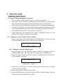
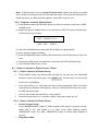
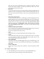
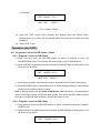
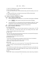
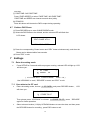
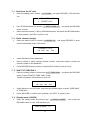
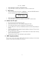
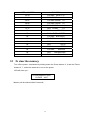
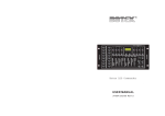
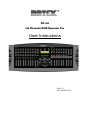
DC-136
136 Channels DMX Operator Pro
User Instructions
Rev 1.1
No. 24-004-1410
DC-136
Table of Contents
1
2
3
4
5
6
7
8
9
10
General Introduction………………………………………………………………………...….. 3
Safety Rules…………………………………………………………………………………….... 3
Notice Information……………………..………………………………………………………... 3
Features and Specifications………………………………………………………………….... 4
4.1 Features………………………………………………………………………….…………4
4.2 Specifications……………………………………………………………………………....4
Basic Control Parts…………………………………………………………………………….. 4
5.1 Front view………………………………………………………………………………….. 4
5.2 Rear view……………………………………………………………………………………6
Operation Guide………………………………………………………………………………….7
(operation upon Fixtures)………………………………………………………………….…7
6.1 Control Fixture channels by “joystick”…………………………………………………... 7
6.2 Program or record a Fixture Scene / Chase…………………………………………….7
6.2.1 Program / record a Fixture Scene………………………………………………7
6.2.2 Program / record a Fixture Chase……………………………………………... 7
6.3 Select or deselect a Fixture Scene / Chase………………………………………….… 8
6.3.1 Select / deselect a Fixture Scene………………………………………….….. 8
6.3.2 Select / deselect a Fixture Chase……………………………………………... 9
6.4 Delete a Fixture Chase…………………………………………………………………... 9
(operation upon PARs)…………………………………………………………………...… 10
6.5 Program or record a PAR Scene / Chase……………………………………………...10
6.5.1 Program / record a PAR Scene………………………………………………..10
6.5.2 Program / record a PAR Chase…………………………………………….... 10
6.6 Select or deselect a PAR Scene / Chase………………………………………..…… 10
6.6.1 Select / deselect a PAR Scene…………………………………………….… 10
6.6.2 Select / deselect a PAR Chase…………………………………………….… 11
6.7 Delete a PAR Chase…………………………………………………………………….. 11
Settings…………………………………………………………………………………………. 12
7.1 Enter the setting mode…………………………………………………….………….… 12
7.2 Save data to the CF card…………………………………………………….…………. 12
7.3 Read from the CF card……………………………………………………………….… 12
7.4 Patch channel (assign)……………………………………………………………….… 12
7.5 PAN / TILT FADE ONLY………………………………………………………………... 13
7.6 Display mode (100/255)…………………………………………………………….….. 13
7.7 MIDI channel………………………………………………………………………….…. 13
Notice for CF Card……………………………………………………………………………... 13
MIDI Implementation……………………………………………………………………….….. 14
To clear the memory…………………………………………………………………….……... 14
2
1 General introduction
Thanks for your purchase of our product DC-136. This unit is a professional 136-channel
DMX console with high performance and advanced capabilities. It is a refined digital light
controller made up of two control parts — one part for Fixtures and one part for PARs, which
can be used to control the Fixtures and the PARs jointly and effectively according to different
requirements towards scenic lighting effect.
2 Safety Rules
In order to use the DC-136 more availably and effectively, please take good care of this
unit. The following rules give important information regarding safety during use and
maintenance.
•
This product is not intended for domestic utilization.
•
keep the unit dry, do not expose it to water or high levels of humid. And never operate
the unit with wetted hands.
•
Do not dismantle or modify the product non-authorizedly.
•
If any liquid is spilled on or in the unit, disconnect the power supply to the product
immediately.
•
Do not open the unit --- there is no user serviceable parts inside.
•
Handle this product carefully, any strong shocks or vibration may result in
malfunction.
•
Do not allow children to tamper or play with this unit.
It is of great benefit for you to keep the Introduction Manual for future reference.
3
Notice Information
•
Before operating, please make sure that the unit has not suffered any damage during
transportation. Should any damage have occurred, please do not use it and contact
the local dealer immediately.
•
We won’t be responsible for any resulting damage due to your inobservance or
improper operation on the unit. Never allow non-authorized or unqualified personnel
with any kind of intervention to the product.
•
Specifications are subject to change without notice. For further information or latest
software updating, please visit our web-site:
www.botex.com
•
Copyright notice: no part of this product can be reproduced, transmitted, or
translated into any language in any form without authorized permission.
3
4 Features and Specifications
4.1
Features
•
Hybrid console for 16 DMX units (8 intelligent fixtures & 8 PARs)
•
6 freely programmable PAR programs, ONE/MIX/SEQ available
•
8 freely programmable fixture programs, MIX/SEQUENCE available
•
136 DMX channels(8 channels for PARs and up to 16 channels per fixture)
•
96 freely programmable fixture scenes / PAR scenes
•
Speed, Fade Time and Master control for chases
•
Joystick for Pan / Tilt & Pan fine / Tilt fine movement of fixture
•
Free access of CF card(32M) for the exchange of data and memories
•
Blackout overall output
•
Fade time/Non-fade time under control
•
Power failure memory and Fog Machine trigger
•
MIDI control over scenes, chases and blackout
•
Audio input and built-in microphone for music sync. function
4.2
Specifications
•
Model
DC-136
•
Power Input
DC 9~15V, 600 mA min.
•
LCD
2×16 characters
•
Audio Trigger
Built-in microphone or line in
•
DMX Output
3 PIN female DMX connector
•
Dimensions
482×178×80mm
•
Weight
Approx.
6.2 kg
5 Basic Control Parts
5.1
•
Front view
SCENE buttons:
Press the scene buttons to load or store relevant Scenes.
•
CHASE buttons:
These buttons are used to load or store relevant Chases.
•
FIXTURE buttons:
To select fixtures for setting, programming or recording.
•
Dimmer faders:
To control and adjust relevant dimming level for each channel.
4
•
PAGE button:
To select relevant Scene-page or Chase-page.
• STEP / MIX / SEQ button:
To activate the “STEP” function or switch between the Mix mode and the Sequence mode.
• TAP SYNC button:
Repeatedly tap this button to establish different chase rate.
• AUDIO button:
Used to activate audio sync of chase rate or set a scene at audio effect.
• GROUP button:
To select more fixtures while holding down this button simultaneously.
• BLACKOUT button:
Press this button to enable or disable relevant DMX output. When its LED is lit, that
means relevant DMX output is disabled. Press this button again the LED will be “off”, that
means the DMX output is reactivated.
• SETUP button:
Press this button for about 3 seconds to access the SETUP menu.
• FOG MACHINE button:
This button is used to control the Fog machine. Relevant LED will show you the different
working states( HEATING or READY ).
• DEL button:
Press this button to delete relevant Scenes or Chases.
• RECORD button:
Press and hold down this button for about 5 seconds to access the Scene/Chase mode,
and also use this button to record Scenes or Chases.
• ESC button:
To cancel relevant operation or to exit.
• UP/DOWN buttons:
To select or adjust desired item or level during operation.
• CH.PAGE button:
Press this button to switch between Ch1-8 and Ch9-16. LED “off ” means 1-8 channels
available, while LED “on “ means 9-16 channels available.
• FINE button:
Use this button can adjust relevant level finely by a small margin .
• “∧∨ < >” buttons:
Used to adjust PAN / TILT movement.
• Joystick:
Used to control and adjust relevant level more conveniently through the Pan or Tilt
movement.
• STANDBY button:
Press this button to enable or disable relevant output of PARs. Its function is similar to the
5
BLACKOUT button.
• FADE+SPEED button:
To select FADE TIME or NO FADE TIME.
• FULL ON button:
Press this button to output all the PARs at full intensity.
• AUTO button:
Used to activate AUTO mode.
• ONE/MIX/SEQ button:
To select One mode, Mix mode or Sequence mode.
• SPEED slider:
Used to set or adjust relevant speed as user’s desire.
• FADE slider:
Used to adjust the FADE TIME level.
• AUDIO slider:
To adjust for best audio effect.
• MASTER slider:
Used to proportionally and totally change the overall console output.
5.2
Rear view
• POWER ON / OFF :
Used to switch on / off the power.
• DC INPUT :
DC 9 ~15V , 600mA min.
• AUDIO LINE INPUT :
0.1V~1Vp-p.
• DMX OUT :
To send DMX data.
• MIDI IN :
Used to receive MIDI data.
• FOG MACHINE INPUT :
To connect with the fog machine.
• CF CARD socket:
It is for CF CARD operation.
• EXT STEP CONTROL INPUT :
To input the external Step Control signals.
6
6 Operation guide
Operation upon Fixtures
6.1 Control Fixture channels by “joystick”
•
This unit has 8 FIXTURE buttons to select 1—8 fixtures respectively.
•
Each fixture can be selected by pressing relevant Chase button. Its LED will be lit
when being selected. Pressing the Chase button again can turn off the fixture.
•
More fixtures can be selected while holding down the “Group” button simultaneously.
•
“Joystick” can be used to control the selected fixtures (its LED will blink) conveniently.
And relevant adjustment will be shown on the LCD-display through 100/255 mode.
•
The disabled fixtures (LED is “off”) will show no signal input.
•
Fixture channel can be controlled by the “joystick”. Adjustment of PAN, TILT, PAN
FINE and TILT FINE are available as user’s desire.
6.2 Program or record a Fixture Scene / Chase
Before programming, press and hold down the RECORD button for about 5 seconds
to enter the Scene/Chase mode, its LED will be lit, LCD shows:
SELECT A SCENE
OR CHASE !
PAGE××
6.2.1 Program / record a Fixture Scene
(1) Press and hold down the RECORD button for about 5 seconds to enter the
CHASE/SCENE mode. Then choose the Scene page by UP or DOWN button.
(2) Select and press a Scene button to be recorded, its LED will begin to blink quickly.
LCD will show you as below:
EDIT SCENE× / PG××
SAVE ESC
PAGE××
(3) Select one or more fixtures, set a scene by faders. User can also insert a recorded
scene for new scene setting.
(4) select another series of fixtures, repeat step (3).
(5) Press RECORD button to record this scene, all LEDs will flash suddenly. User can
then set and record another Scene as desire.
7
Note: In Record mode, user can delete a Fixture Scene. Select and press a recorded
Scene button in the Record mode, its LED will blink quickly. Then press the DEL button to
delete the scene, all LEDs will blink suddenly. (Press ESC button to exit.)
6.2.2 Program / record a Fixture Chase
(1) Press and hold down the RECORD button for about 5 seconds to enter the CHASE /
SCENE mode.
(2) Select and press a Chase button to be recorded, its LED will begin to blink quickly.
LCD will show you as below:
EDIT CHASE× / TL××
ADD
ESC
STEP××
(3) Use UP or DOWN button to select the Chase Step to be programmed.
(4) Set a scene for Chase recording.
(5) Press the RECORD button, all LEDs will blink briefly, and LCD will show you the new
step.
(6) Pressing the DEL button can delete the current step, all LEDs will blink briefly.
(7) User can press ESC button to exit .
6.3
Select or deselect a Fixture Scene / Chase
6.3.1 Select / deselect a Fixture Scene
•
Press “PAGE” button, the relevant LED will light up, you can just use UP/DOWN
buttons to select the scene page. And
PAGE : ××
will be shown on the top left
corner of the LCD-display.
•
If the scene LED is “on”, that means the scene was programmed, while “off” means
unprogrammed. When the LED lights up, press its relevant button to start the scene,
the LED will start to flash.
•
You can also control the channels by using “joystick”.
•
Press the scene button for 1 second to restart , and press it again for “off ”.
6.3.2 Select / deselect a Fixture Chase
•
Choose program mode:
Press “MIX/SEQUENCE” button to select program mode when no program running.
When LED is “on”, that means it is in “MIX” mode, while “flashing” means
“SEQUENCE” mode. The “MIX / SEQUENCE” button is useless when program is
running .
•
Sequence mode:
8
Enter this mode, press corresponding buttons to operate the programs. The LED
flashes when relevant program runs, while other LEDs don’t flash. Close all the
running programs before exit this mode.
•
Mix mode:
In this mode, LEDs (relevant to the running programs) will flash simultaneously and
programs can also run synchronously. If there are several programs going upon one
fixture, the last one should be effective. Close all the running programs before exit
this mode.
•
Select Chase speed mode
Press a programmed Chase button, its LED will be lit to indicate its Speed mode. Fast
flashing means user can set the speed by SPEED Slider or the TAP SYNC button,
while slow flashing means the Chase speed has already been programmed (Speed
adjusting will be of no effect at this moment). User can switch the Chase speed
mode by pressing the “STEP/MIX/SEQ” button while pressing and holding
down the programmed Chase button. ( the priority of Chasing sequence keeps
unaffected.)
•
Operate relevant chase by faders
You can control any of the channels by faders while the chase running. If you want to
return to its former track, please press any of the chase button .
All scenes are disabled when chases running.
•
STEP
Press STEP button, the chase will step forward while the program running.
•
AUDIO
Press AUDIO button while chase running, the AUDIO LED will light up, that means
you have entered the “AUDIO” mode. FADE TIME will be useless, and the “TAP
SYNC” LED will blink according to the audio effect.
•
FADE TIME/SPEED
If the chase runs under the SPEED MODE which set by the SPEED slider or TAP
SYNC button, you can then use the SPEED and FADE faders to control SPEED and
FADE TIME.
•
PAN/TILT FADE ONLY
You can select relevant channel only for PAN/TILT, or select all channels for FADE
TIME.
6.4 Delete a Fixture Chase
(1) Press RECORD button for about 5 seconds to enter CHASE/SCENE mode.
(2) Select the Fixture Chase to be deleted, relevant LED will flash fast.
9
LCD shows:
EDIT CHASE× / TL××
ADD
ESC
STEP××
(“TL××” means “TOTAL” )
(3) press the “DEL” button while pressing and holding down the Chase button
simultaneously, the chase will be deleted within few seconds (all LEDs will blink
suddenly).
(4) Press “ESC” to exit.
Operation upon PARs
6.5
Program or record a PAR Scene / Chase
6.5.1 Program / record a PAR Scene
(1) Press and hold down the RECORD button for about 5 seconds to enter the
CHASE/SCENE mode. Then choose the Scene page by UP or DOWN button.
(2) Select and press a Scene button to be recorded, its LED will begin to blink quickly. LCD
will show you as below:
EDIT SCENE× / PG××
SAVE ESC
PAGE××
(3) Set a scene by faders. User can also insert a recorded scene for new scene setting.
(4) Press RECORD button to record this scene, all LEDs will flash suddenly. User can then
set and record another Scene as desire.
Note: In Record mode, user can delete a PAR Scene. Select and press a recorded Scene
button in the Record mode, its LED will blink quickly. Then press the DEL button to delete
the scene, all LEDs will blink suddenly. (Press ESC button to exit.)
6.5.2 Program / record a PAR Chase
(1) Press and hold down the RECORD button for about 5 seconds to enter the CHASE /
SCENE mode.
(2) Select and press a Chase button to be recorded, its LED will begin to blink quickly. LCD
will show you as below:
EDIT CHASE× / TL××
10
ADD
ESC
STEP××
(3) Use UP or DOWN button to select the Chase Step to be programmed.
(4) Set a scene for Chase recording.
(5) Press the RECORD button, all LEDs will blink briefly, and LCD will show you the new
step.
(6) Pressing the DEL button can delete the current step, all LEDs will blink briefly.
(7) User can press ESC button to exit .
6.6
Select or deselect a PAR Scene / Chase
6.6.1 select / deselect a PAR Scene
(1)
Press the PAGE button, its LED will be lit, you can select t scene page by UP/DOWN
button.
(2)
PAGE:×× will be shown on the top left corner of the LCD-display.
If the Scene LED is “on”, that means the scene was programmed. While “off ” means
unprogramed. Press the programmed Scene button to reactivate the PAR Scene.
(3)
Pressing the scene button again can disable the related Scene.
6.6.2 select / deselect a PAR Chase
(1) Choose chase mode:
Press ONE/MIX/SEQ button to select the chase mode when no chase running. “off ” LED
means “ONE” mode, “on” LED means “MIX” mode, and “flashing” LED means “SEQ”
mode. It would be ineffective when chase running.
(2) “ONE” mode:
Enter this mode, then press the programmed chase button, the relevant LED will light up.
The other running PAR chases will be closed.
close all the running chases when exit this mode.
(3) SEQUENCE mode:
In this mode, you should press the programmed chase buttons in turn to operate the
chases. The relevant LEDs will flash when chases are running.
Close all the running chases when exit this mode.
(4) MIX mode
In this mode, chases can run at the same time. The relevant LEDs will light up when
programs running. You should close all the running chases when exit.
(5) AUDIO
Press AUDIO button while chase running, the AUDIO LED will light up, that means you
have entered the “AUDIO” mode. FADE TIME will be useless, and the “TAP SYNC” LED
will flash according to the audio effect.
(6) STEP
Press “STEP” button, the relevant LED will blink briefly, and the chase will go forward for
11
one step.
(7) FADE TIME / NO FADE TIME
Press “FADE+SPEED” to select “FADE TIME / NO FADE TIME”.
FADE TIME and SPEED can interact on each other jointly.
(8) STAND BY
Press this button will shutter the PAR’s output during operating.
6.7 Delete a PAR Chase
(1) Press RECORD key to enter CHASE/SCENE mode.
(2) Select the PAR Chase to be deleted, and the relevant LED will flash fast.
LCD shows:
EDIT CHASE X/TL××
ADD
ESC
STEP××
(3) Press the corresponding Chase button and “DEL” button simultaneously, and then the
Chase can be deleted within few seconds.
(4) Press ”ESC” to exit.
7 Settings
7.1
•
Enter the setting mode
Press SETUP for 5 seconds while no program running, relevant LED will light up. LCD
will show you:
↓
1. CF CARD
2.
ASSIGN
CH.
( 3.P/T FADE ONLY 4.DISPLAY MODE
5.MIDI CH. )
Use UP/DOWN” to scroll, “RECORD” to enter, and “ESC” to exit.
7. 2 Save data to the CF card
•
Enter the setting mode, choose
1. CF CARD
and press RECORD button ,
LCD
will show you:
1.
READ FROM CF
2.
STORE TO CF
Then please press “UP/DOWN” to choose
2 .STORE TO CF , press
“RECORD”
again for further operation.
•
Select relevant location (1-99) by UP/DOWN buttons to save the data, and then press
the RECORD button for recording , press ESC button to exit.
12
7. 3
•
Read from the CF card
Enter the setting mode, choose
1. CF CARD
and press RECORD , LCD will show
you:
•
1.
READ FROM CF
2.
STORE TO CF
Use UP/DOWN buttons to choose
1. READ FROM CF
, and press the RECORD
button to enter.
•
Select relevant location (1-99) by UP/DOWN buttons, and press the RECORD button
for data reading, use ESC to cancel or exit.
7. 4 Patch channel (assign)
•
Enter the setting mode to choose 2. ASSIGN CH. , and press RECORD to enter
channel distributing mode. LCD shows:
CHANNEL1 > OUT1
OK ESC SEL
ADJ
•
select the fixtures to be distributed.
•
Use UP button to select relevant channel number, and press DOWN to select the
channel number to be distributed.
•
Press RECORD button to confirm, and press ESC button to cancel or exit.
7. 5 PAN / TILT FADE ONLY
•
Enter the setting mode to choose item 3. P/T FADE ONLY , and press the RECORD
button to enter “PAN/TILT FADE ONLY” mode.
Further information will be shown on the LCD:
FIXTURE1: ONLY
OK ESC SEL ADJ
•
Select fixtures by the UP button, and press the DOWN button to select “FADE ONLY”
or ”FADE ALL”.
•
Press “RECORD” to confirm your operation, and “ESC” to cancel or exit.
7. 6 Display mode (100/255)
•
Enter the setting mode and choose item
4. DISPLAY MODE
RECORD button to enter. LCD will show you:
DISPLAY MODE : ×××
13
, then press the
OK ESC CHANGE
•
Select mode100 or mode255 by UP/DOWN buttons.
•
Press “RECORD” to confirm your operation, use “ESC” to cancel or exit.
7. 7
•
MIDI channel
Enter the setting mode and choose
5. MIDI CH.
, then press RECORD button to
enter the relevant further operation. LCD will show you:
MIDI CH. <××>
OK ESC CHANGE
•
Select relevant MIDI channels(1-16) by UP/DOWN buttons.
•
Press “RECORD” to confirm your operation, and use “ESC” to cancel or exit.
8 Notice for CF card
•
Do not pull out the CF card when being used.
•
Power must be assured “on”, when reading or storing to CF card.
•
Turn off the power when connect or disconnect CF card with the unit.
•
CF card (32M) can be used only for DC-136, otherwise the data would probably be
missing.
•
Outputting of DMX would be stopped during the reading or storing to CF card. And so
does to “ASSIGN CH.” mode.
•
CF card may become hot during use. Please observe due caution when removing
memory cards from this device.
•
Take good care of the CF card, and keep it in good conditions.
9 MIDI Implementation
This unit can receive and transmit MIDI NOTE information according to the relevant
channels. Please keep the following list for reference.
14
NOTE
NUMBER
FUNCTION
22-33
FIXTURE
PAGE 1-12
34-49
PAR
50-57
FIXTURE SCENE 1-8
58-65
FIXTURE CHASE 1-8
66-71
PAR
SCENE
1-6
72-77
PAR
CHASE
1-6
78
PAR
STANDBY
79
PAR
FADE + SPEED
80
FIXTURE
BLACKOUT
81
FIXTURE
AUDIO
82
PAR
AUDIO
83
PAR
AUTO
84
PAR
STEP
85
FIXTURE
86
PAR
ONE/MIX/SEQ
87
PAR
FULL ON
PAGE
1-16
MIX/SEQ
10 To clear the memory
Turn off the power, simultaneously holding down the Chase buttons 3, 6 and the Fixture
buttons 2, 7 , and at the same time, turn on the power.
LCD will show you :
CLEAR MEMORY NOW
PLEASE
WAIT..
Memory will be cleared within 5 seconds.
15