1
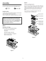
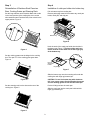
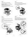
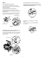
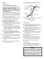
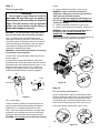
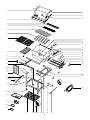
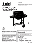
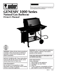
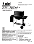
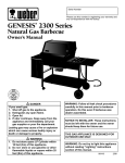
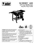
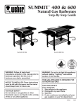
PLATINUM™ 1200 Series
Natural Gas Barbecue
Step-By-Step Instructions
Serial Number
Please use this number in registering your warranty and
any correspondence with the factory.
E
WEB
WEB
ER
gama
R
®
WARNING: Follow all leak check
procedures carefully in this manual prior
to barbecue operation. Do this even
though the barbecue is assembled.
NOTICE TO INSTALLER: These
instructions must be left with the owner
and the owner should keep them for
future use.
FOR YOUR SAFETY
Do not store or use gasoline or other
flammable vapors and liquids in the
vicinity of this or any other appliance.
WARNING: Do not try to light this
appliance without reading "Lighting"
instructions section of this manual.
THIS GAS APPLIANCE IS DESIGNED FOR
OUTDOOR USE ONLY.
FOR YOUR SAFETY
If you smell gas:
1. Shut off gas to the appliance.
2. Extinguish any open flame.
3. Open lid.
4. If odor continues, immediately call
your gas supplier or your fire
department.
© 1994, Weber-Stephen Products Co.
87765
4/94
Assembly
Step 2
Remove packaged parts
Tools needed
Remove and unpackage warming rack, Weber Warm-Up
Basket, 2 cooking grates, cardboard box (which contains
cookbook and warranty card), 8 short stainless steel
Flavorizer Bars and 5 long stainless steel Flavorizer
Bars.
3/4 and 7/16 inch open-end or an adjustable wrench
Note - Be sure no packaging material is left in the
cooking box before reinstalling parts.
Supplies needed
You will need a soap and water solution to check for gas
leaks. (See Step "Check for gas leaks.")
Warming basket
Refer to exploded view if replacement parts are needed.
Weber Warm-Up Basket
While we give much attention to our products, unfortunately an occasional error may occur. If a part is
missing, do not go back to the store. Call the Weber
Customer Service Center toll free 1-800-446-1071 to
receive immediate assistance. Have your owner’s
manual available for reference.
Cooking grates
Short Stainless Ísteel
Flavorizer Bars
Long Stainless Steel
Flavorizer Bars
Step 1
Removal of all tape
Remove tape from the following locations:
front and rear of side work table
swing table
swing table support rod holder
bottom tray beneath the cooking box
bottom accessory trays
Figure 2
Figure 1
2
Step 3
Step 4
Reinstallation of Stainless Steel Flavorizer
Bars, Cooking Grates and Warming Rack
Installation of catch pan holder into bottom tray
Pull out bottom tray from cooking box.
Remove packaging material from bottom tray, catch pan
holder, catch pan, and drip pan.
Set the long stainless steel Flavorizer Bars side to side
in the lower position of the cooking box, then set the
short stainless steel Flavorizer Bars, front to back in the
upper position. Figure 3.
Bottom tray
Figure 6
Hook the ends of the catch pan holder into the hole in
the bottom tray. Figure 7. The front of the catch pan
holder must be on the same side as the finger grip
of the bottom tray.
Figure 3
Set the cooking grates onto the ledges in the cooking
box. The open "U" of the cooking grate goes down.
Figure 4.
Front of
catch pan
holder
Finger grip
Figure 7
Slide the bottom tray onto the mounting rails under the
cooking box with finger grip toward you.
CAUTION: Do not line bottom tray with aluminum
foil. It can cause grease fires by trapping the grease
and not allowing grease to flow into the catch pan.
Figure 4
Put the foil drip pan into the catch pan.
Set the warming rack into the slots at the rear of the
cooking box. Figure 5.
Slide the catch pan into the catch pan holder with its
finger grip towards you.
Figure 5
3
Step 5
Step 7
Remove grill from lower packaging
Install Weber Warm-Up Basket
Make sure natural gas hose is free from lower
packaging before lifting.
Insert one end of the Weber Warm-Up Basket into the
hole in the right end of the lid and the other end into the
slot in the left end of the lid. Figure 10.
WARNING: Lifting the barbecue from the lower
packaging requires at least two people.
With two people lift straight up and over lower packaging
and cardboard support.
Figure 10
Figure 8
Step 8
Step 6
Remove control panel
Install Lid
Remove the burner control knobs. Figure 11 (a). Grasp
the under the edge of the control panel at the control
panel push-in buttons and slide along the frame toward
you. Figure 11 (b). Lift off the control panel.
Remove hinge pins and hair pin cotters from back of
cooking box.
Set the lid in place. Align the hinges at the rear of the
barbecue. Insert hinge pins from the outside. Insert hair
pin cotters into the small holes in the hinge pins.
Figure 9.
Remove tape securing the thermometer into its holder.
Hair pin cotter
Hinge pin
(a)
control panel push-in
buttons
(b)
Figure 9
Figure 11
4
Step 9
Check that all the burner valves are off. Figure 14.
Check that items are secured
Valves are shipped in the OFF position, but you should
check to be sure. Put the knob on each valve. Check by
pushing down and turning clockwise.
Note - Although the following items were factory
assembled, check that they have not loosened during
shipping and handling.
Remove the tape from the manifold bracket.
Check that the bracket is securely hooked onto the
frame brace and under the manifold at the center burner
valve. Figure 12.
If it is loose lift the bracket, manifold and cooking box
slightly as a unit and reposition onto the frame brace.
Manifold Bracket
Figure 14
Check connection of flexible hose to manifold.
Figure 15.
If the connection is loose it should be tightened
with a wrench.
Manifold Bracket
Figure 12
Check that the igniter is secure in the frame brace and
has not shifted out of the key hole. Figure 13.
If it is loose, slide the igniter into the rear of the key hole.
Carefully tighten the igniter lock nut with an adjustable
wrench or pliers.
Figure 15
Igniter lock nut
Figure 13
5
Step 10
Typical natural gas supply installation. Figure 16.
Install gas supply
Gas supply
General Specifications for Piping
Inside wall
Note - Contact your local municipality for building
codes regulating outdoor gas barbecue
installations. In absence of Local Codes, you must
conform to the latest edition of ANSI Z223.1. WE
RECOMMEND THAT THIS INSTALLATION BE DONE
BY A PROFESSIONAL.
Outside wall
Some of the following are general requirements taken
from ANSI Z223.1, for gas supply installations. Refer to
ANSI Z223.1 latest edition for complete specifications.
Quick Disconnect
■
This barbecue is designed to operate at 7 inches of
water column pressure (.2526 psi).
■
A manual shut-off valve must be installed outdoors,
immediately ahead of the quick disconnect.
Shut off
The quick disconnect is installed
above ground
CAUTION: If young children are in the area, a
locking valve should be considered.
■
■
■
Figure 16
An additional manual shut-off valve indoors should
be installed in the branch fuel line in an accessible
location near the supply line.
Gas line piping
The quick disconnect connects to a 3/8 inch NPT
thread from the gas source. The quick disconnect
fitting is a hand-operated device that automatically
shuts OFF the flow of gas from the source when the
barbecue is disconnected.
The quick disconnect fitting can be installed
horizontally, or pointing downward. Installing the
fitting with the open end pointing upward can result
in collecting water and debris.
■
The dust covers (supplied plastic plugs) help keep
the open ends of the quick disconnect fitting clean
while disconnected.
■
Pipe compound should be used which is resistant to
the action of natural gas when connections are
made.
■
The outdoor connector must be firmly attached to
rigid, permanent construction.
Locking shut off
■
If the length of line required does not exceed 50
feet, use a 5/8" O.D. tube. One size larger should be
used for lengths greater than 50 feet.
■
Gas piping may be copper tubing, type K or L;
polyethylene plastic tube, with a minimum wall
thickness of .062 inch; or standard weight (schedule
40) steel or wrought iron pipe.
■
Copper tubing must be tin-lined if the gas contains
more than 0.3 grams of hydrogen sulfide per 100
cubic feet of gas.
■
Plastic tubing is suitable only for outdoor,
underground use.
■
Gas piping in contact with earth, or any other
material which may corrode the piping, must be
protected against corrosion in an approved manner.
■
Underground piping must have a minimum of
18" cover.
Test connections
All connections and joints must be thoroughly tested for
leaks in accordance with local codes and all listed
procedures in the latest edition of ANSI Z223.1.
DANGER
Do not use an open flame to check for
gas leaks. Be sure there are no sparks or
open flames in the area while you check for
gas leaks. This will result in a fire or
explosion which can cause serious bodily
injury or death, and damage to property.
6
Step 11
Check:
Check for gas leaks
a) Hose to manifold connection. Figure 18 (a).
WARNING: If there is a leak at connection a,
retighten the fitting with a wrench and recheck for
leaks with soap and water solution.
DANGER
Do not use an open flame to check for
gas leaks. Be sure there are no sparks or
open flames in the area while you check for
leaks. This will result in a fire or explosion
which can cause serious bodily injury or
death and damage to property.
If a leak persists after retightening the fitting, turn
OFF the gas. DO NOT OPERATE THE BARBECUE.
Contact your dealer.
b) Valves to manifold connections. Figure 18 (b).
c) Hose to quick disconnect connection. Figure 18 (c).
WARNING: If there is a leak at connections b or c,
turn OFF the gas. DO NOT OPERATE THE
BARBECUE. Contact your dealer.
WARNING: You should check for gas leaks every
time you disconnect and reconnect a gas fitting.
When leak checks are complete, turn gas supply OFF at
the source and rinse connections with water.
Note - All factory made connections have been
thoroughly checked for gas leaks. The burners have
been flame tested. As a safety precaution you should
recheck all fittings for leaks before using your Weber
Gas Barbecue. Shipping and handling may have
loosened or damaged a gas fitting.
(a)
WARNING: Perform these leak checks even though
your barbecue was assembled.
(b)
You will need: a soap and water solution and a rag or
brush to apply it.
To perform leak checks: Slide back the collar of the
quick disconnect. Push male fitting of the hose into the
quick disconnect, and maintain pressure. Figure 17 (a).
Slide the collar closed. Figure 17 (b). If it does not
engage or lock, repeat procedure. Gas will not flow
unless the quick disconnect is properly engaged.
(c)
(a)
Collar
(b)
Figure 18
Male fitting
Step 12
Quick disconnect
engaged
Put the control panel back on
Set the control panel in place over both frame braces.
(Hold the Crossover Ignition button up while setting the
control panel in place.) Place your thumbs over the
control panel push-in buttons, and push them into the
frame brace until they snap into place. Figure 19 (a).
Figure 17
Turn on gas supply.
Check for leaks by wetting the connections with the
soap and water solution and watching for bubbles. If
bubbles form or if a bubble grows there is a leak.
Push on the burner control knobs. Figure 19 (b).
Note - Since some leak test solutions, including soap
and water, may be slightly corrosive, all connections
should be rinsed with water after checking for leaks.
WARNING: Do not ignite burners when leak checking.
(a)
(b)
Figure 19
7
1
34
35
®
®
36
2
3
4
5
6
7
37
38
39
40
41
42
43
44
45
8
9
11
46
47
48
12
49
10
13-14
15
16
50-54
55
17
18-19,14
10,14
56
20
21
W
22
W
23
E BE R
E BE R
24
25
26 27 28
31
32
29 30
8
33
Parts List
Contact:
All items are single quantities unless otherwise
specified.
Parts can be ordered directly from Weber-Stephen
Products Company by phone or mail.
Note - Do not return parts to Weber-Stephen Products
Co. without first contacting the Customer Service Center
by phone or mail. Returning the part may not be
necessary.
1
2
3
4
5
6
7
8
9
10
11
12
13
14
15
16
17
18
19
20
21
22
23
24
25
26
27
28
29
30
31
32
33
34
35
36
37
38
39
40
41
42
43
44
45
46
47
48
49
50
51
52
53
54
55
56
Lid (assembly)
Lid handle
Warm-Up Basket
Warming rack
Stainless Steel short Flavorizer bars (8)
Stainless Steel long Flavorizer bars (5)
Cooking grates (2)
Work table
Tubing plugs (5)
1/4-20 x 2 inch bolts (5)
Swing table end bracket
Left frame
1/4-20 x 1/2 inch bolts (6)
1/4 inch nylon washers (13)
Caster frame
Swing table assembly
Left hand slide bar assembly
10-24 x 1 3/4 inch machine screws (2)
10-24 hex nuts (2)
Casters (2)
Bottom tray
Catch pan holder
Catch pan
Drip pans (2)
Accessory trays (2)
Frame connectors (2)
Wheel hubcaps (2)
Wheels (2)
Tool holders (3)
Wheel frame
Front panel
Plastic buttons (2)
Axle
Weber-Stephen Products Company
Customer Service Center
250 South Hicks Road
Palatine, IL 60067-6241
(708) 705-8660
(800) 446-1071
Hair pin cotters (2)
Hinge pins (2)
Thermometer
1/4-20 acorn nut
Cooking box
Burner control knobs (3)
Control panel
Igniter button
Control panel push-in-buttons (2)
Crossover tube
Front and back burners (2)
Center burner
1/4-20 x 1/2 inch thumbscrews (2)
Spider Stopper Guards (3)
Manifold assembly
Manifold bracket
Igniter
Igniter lock nut
Gas catcher ignition chamber
Igniter wire (black)
Igniter wire (white)
Right frame
Hose
Note - The hardware size of nuts, bolts and screws is
given. For example "1/4-20 x 2 inch bolt" means a bolt
1/4 inch in diameter with 20 threads to the inch, 2 inches
long. On a small screw for example, "6-32 x 1/2 inch
screw" means a number 6 screw, with 32 threads to the
inch, 1/2 inch long.
WARNING:
Use only Weber factory authorized parts.
The use of any part that is not factory
authorized can be dangerous. This will also
void your warranty.
9
A FINAL WORD
OF THANKS
hank you for choosing a Weber Barbecue.
TOur
family here at Weber has worked hard
to produce the highest quality products
for your satisfaction.
While we give much attention to our products, an
occasional error may occur. Our knowledgeable
Customer Service staff is prepared to help you
with any problems with parts or assembly.
Call our toll free number 1-800-446-1071.
For quicker service, please have your owner’s
manual available for reference. We also welcome
any comments or suggestions you might have
regarding our products.
We wish your family the
best in outdoor cooking enjoyment.
Weber-Stephen Products Company
Customer Service Center
200 East Daniels Road
Palatine, Illinois 60067-6266
Printed on recycled paper