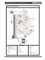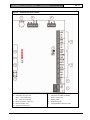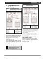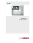
1
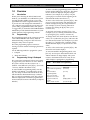
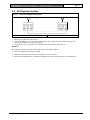
ICP-CC488
Quick Reference Guide
EN
ICP-CC488
Control Panel
ICP-CC488 | Quick Reference Guide | Notices
EN | 2
Copyright Notice
Notice of Liability
Unless otherwise indicated, this publication is the
copyright of Bosch Security Systems, Inc. (“Bosch”).
All rights are reserved.
This material is designed for use by tradespeople with
expertise in the installation of this product. Persons
without appropriate expertise should seek assistance
before attempting installation.
You may download a single copy of this publication.
By downloading the publication you agree that you
will: (i) only use the publication for your own
reference; (ii) not commercially exploit or charge any
person for the use of the publication; and (iii) not
modify the publication in any way without the prior
written permission of Bosch.
Except as specified above or where authorized by the
Copyright Act 1968 (Cth), no part of this publication
may be reproduced, transmitted, modified or stored,
in any form or by any means, without the prior
written permission of Bosch.
Bosch Security Systems, Inc. | 12/08 | F01U089458-02
While care has been taken in the preparation of this
material, Bosch Security Systems, Inc. and its
representatives will not be responsible to any person
or entity for any loss or damage directly or indirectly
caused by information in, or any omission from, this
material.
Bosch Security Systems, Inc. reserves the right to
make changes to features and specifications of its
products at any time without prior notification.
ICP-CC488 | Quick Reference Guide | Contents
Contents
1.0
1.1
1.2
1.3
1.4
1.5
1.6
1.7
1.7.1
1.7.2
1.8
1.8.1
1.8.2
1.9
1.10
1.11
1.12
1.13
1.14
1.14.1
1.14.2
1.14.3
1.15
1.16
1.17
1.18
1.19
1.20
1.21
1.22
1.23
1.24
1.25
1.26
1.27
1.28
1.29
Overview...........................................................6
Introduction ......................................................6
Programming ....................................................6
Programming Using A Codepad ....................6
Programming Option Bits ...............................7
Installer’s Programming Commands..............7
Arming/Disarming the System .......................8
Isolating Zones..................................................8
Standard Isolating.............................................8
Code to Isolate..................................................8
Add/Delete RF Devices (Wireless Zones) .....8
Add RF Device.................................................8
Delete RF Device .............................................8
Set First Test Report ........................................8
Event Memory Recall ......................................8
Walk Test Mode ...............................................8
Satellite Siren Service Mode ...........................8
Telephone Monitor Mode (Toggle On/Off) .9
Add/Delete User Code/RF Keyfob ...............9
Add A User Code ............................................9
Add RF Keyfob ................................................9
Delete a User Code/RF Keyfob .....................9
Change Domestic Telephone Numbers.........9
Turn Outputs On/Off ......................................9
Setting Date and Time .....................................9
Day Alarm – Toggle On/Off ..........................9
STAY Mode 2 Zones – Program....................9
Fault Analysis..................................................10
Modem Call (Alarm Link).............................10
Latching Outputs (Reset) ...............................10
Codepad ID/Buzzer Tone.............................10
Test Report .....................................................10
Speaker Test....................................................10
Bell Test...........................................................10
Strobe Test (Toggle On/Off).........................10
Telco Arm Sequence (Call Forward On).....10
Telco Disarm Sequence (Call Forward Off) 10
2.0
2.1
2.1.1
2.1.2
2.1.3
2.1.4
2.1.5
2.1.6
2.1.7
2.1.8
Programming Parameters ..............................11
Phone Programming ......................................11
Phone Number 1 - Receiver 1 ......................11
Phone Number 2 - Receiver 1 ......................11
Handshake Tone For Receiver 1..................11
Transmission Format For Receiver 1...........11
Subscriber ID Number For Receiver 1........11
Phone Number 1 - Receiver 2 ......................11
Phone Number 2 - Receiver 2 ......................11
Handshake Tone For Receiver 2..................11
Bosch Security Systems, Inc. | 12/08 | F01U089458-02
EN | 3
2.1.9
2.1.10
2.1.11
2.1.12
2.1.13
2.1.14
2.1.15
2.1.16
2.1.17
2.1.18
2.1.19
2.1.20
2.1.21
2.2
2.3
2.3.1
2.3.2
2.4
2.5
2.6
2.6.1
2.6.2
2.6.3
2.6.4
2.6.5
2.6.6
2.6.7
2.6.8
2.7
2.7.1
2.7.2
2.8
2.8.1
2.8.2
2.8.3
2.8.4
2.8.5
2.8.6
2.8.7
2.9
2.9.1
2.9.2
2.9.3
2.9.4
2.9.5
2.10
2.10.1
2.10.2
2.10.3
2.10.4
Transmission Format For Receiver 2 ...........11
Subscriber ID Number For Receiver 2 ........11
Dialing Format................................................11
Reserved ..........................................................12
Telco Arming Sequence (Call Forward On)12
Telco Disarm Sequence (Call Forward Off) 12
Call Back Telephone Number ......................12
Ring Count......................................................12
Telephone Line Fail Options ........................12
Dialer Options 1 .............................................12
Dialer Options 2 .............................................12
Dialer Options 3 .............................................12
Alarm Link Options .......................................12
Installer Code..................................................12
User Code Programming...............................12
User Codes......................................................12
Authority Levels .............................................13
Day Alarm Zones ...........................................13
EOL Resistor Value .......................................13
Zone Programming ........................................13
Zone Defaults ..................................................13
Zone Types......................................................14
Zone Pulse Count ...........................................14
Zone Pulse Count Time .................................15
Zone Options 1...............................................15
Zone Options 2...............................................15
Zone Dialer Options ......................................15
Keyswitch Zone Options ...............................15
Swinger Programming ...................................15
Swinger Shutdown Count For Siren.............15
Swinger Shutdown Count For Dialer ...........15
Zone Status Programming .............................15
Zone Status – Zone Tamper Report.............15
Zone Status – Walk Test Report ...................15
Zone Status – Bypass Report.........................15
Zone Status – Trouble Report.......................15
Zone Status – Sensor Watch Report.............15
Zone Status – Alarm Restore Code ..............15
Zone Status Reporting Options.....................15
RF Programming ............................................15
RF Supervision Time .....................................15
RF Low Battery Report..................................15
RF Receiver Trouble Report.........................16
RF Receiver Trouble Restore Report ..........16
RF Dialer Options ..........................................16
Report Programming .....................................16
Open/Close Reports ......................................16
Open/Close Reporting Options....................16
Codepad Duress Report ................................16
Codepad Panic Report...................................16
ICP-CC488 | Quick Reference Guide | Contents
2.10.5
2.10.6
2.10.7
2.11
2.11.1
2.11.2
2.11.3
2.11.4
2.11.5
2.11.6
2.11.7
2.11.8
2.12
2.12.1
2.12.2
2.13
2.13.1
2.13.2
2.13.3
2.13.4
2.13.5
2.13.6
2.13.7
2.14
2.14.1
2.14.2
2.14.3
2.14.4
2.14.5
2.14.6
2.14.7
2.14.8
2.14.9
2.14.10
2.14.11
2.14.12
2.14.13
2.14.14
2.15
2.15.1
2.15.2
2.15.3
2.15.4
2.15.5
2.15.6
2.15.7
2.15.8
2.15.9
2.15.10
Codepad Fire Report .....................................16
Codepad Medical Report ..............................16
Codepad Reporting Options.........................16
System Status Programming..........................16
System Status – AUX Power Supply Fail
Report..............................................................16
System Status – AUX Power Supply Fail
Restore Report................................................16
System Status – AC Fail Report ...................16
System Status – AC Fail Restore Report .....16
System Status – Low Battery Report............16
System Status – Low Battery Restore Report16
System Status – Access Denied (Code Retry)16
System Status Reporting Options .................17
Test Report Programming.............................17
Test Report Time (Automatic) ......................17
Test Reporting Dialer Options .....................17
Output Programming.....................................17
Outputs ............................................................17
Event Codes....................................................18
Polarity (Modes) .............................................19
Time Base........................................................19
Time Base Multiplier .....................................19
One Shot Mode ..............................................19
Pulsing Mode ..................................................19
Time Programming ........................................19
Entry Time 1...................................................19
Entry Time 2...................................................19
Exit Time (AWAY/STAY Modes) ...............19
Entry Guard Time For STAY Mode............19
Delay Alarm Report Time ............................19
Sensor Watch Time........................................19
Codepad Lockout Time.................................19
Siren Run Time ..............................................19
Siren Sound Rate............................................19
Auto Arming Pre-Alert Time ........................19
Auto Arming Time.........................................19
Auto Disarming Time ....................................20
Kiss-Off Wait Time ........................................20
Speaker Beep Volume ...................................20
Options Programming ...................................20
System Options 1 ...........................................20
System Options 2 ...........................................20
System Options 3 ...........................................20
System Options 4 ...........................................20
Consumer Options 1......................................20
Consumer Options 2......................................20
Consumer Options 3......................................20
Radio Input Options ......................................20
Partitioning Options 1....................................20
Partitioning Options 2....................................20
Bosch Security Systems, Inc. | 12/08 | F01U089458-02
EN | 4
2.16
2.16.1
2.20.5
2.20.6
2.20.7
2.21
2.21.1
2.21.2
2.21.3
2.21.4
Zone Allocations Programming ....................21
Zone Allocations Enabled for Area 1 and
Area 2 ..............................................................21
Zone Allocations for Area 1 and Area 2......21
User Code Area Assignment.........................21
Domestic Telephone Numbers .....................21
Reserved ..........................................................21
RF Programming ............................................21
RF Options......................................................21
RF Device Mapping Option..........................22
Default RF Device Mapping for Devices 1 to
8........................................................................22
Default RF Device Mapping for Devices 9 to
16......................................................................22
RF Signal Strength for Devices 1 to 8 ..........22
RF Signal Strength for Devices 9 to 16 ........23
Reserved ..........................................................23
System Option Programming........................23
Country Codes................................................23
Default Options ..............................................23
System Time ...................................................23
System Date ....................................................23
3.0
RF Receiver Interface ....................................24
4.0
RF Keyfob Operations...................................25
5.0
5.1
5.2
Connections for Split EOL Resistors............25
8 Burglary Zones ............................................25
8 Zone Operation Using N/O Contacts.......26
6.0
Wiring Diagrams ............................................26
7.0
Codepad Connections Partitioning...............29
8.0
Country Codes................................................30
2.16.2
2.17
2.18
2.19
2.20
2.20.1
2.20.2
2.20.3
2.20.4
ICP-CC488 | Quick Reference Guide | Contents
EN | 5
Figures
Tables
Figure 1:
Figure 2:
Figure 3:
Figure 4:
Table 1:
Table 2:
Table 3:
Table 4:
Table 5:
Table 6:
Table 7:
Table 8:
Table 9:
RF Receiver (DSRF) Wiring Diagram ..24
RF3332: 2-Button Keyfob Transmitter .25
RF3334: 4-Button Keyfob Transmitter .25
Split EOL Wiring Diagram (Location
266 – 15)...................................................25
Figure 5:
Split EOL Wiring Diagram with Tamper
(Location 266 – 14) .................................25
Figure 6:
Split EOL Wiring Diagrams Using N/O
Contacts....................................................26
Figure 7:
Wiring Diagram for Keyswitch Zone....26
Figure 8:
ICP-CC488 Wiring Diagram .................27
Figure 9:
ICP-CC488 Component Overlay..........28
Figure 10: Connections for CP-5 Master Partitioned
Codepad and CP-5 Area Addressable
Codepad ...................................................29
Figure 11: Connections for Two CP-5 Area
Addressable Codepads ...........................29
Bosch Security Systems, Inc. | 12/08 | F01U089458-02
Quick Guide to Programming .................6
Codepad Indicators...................................7
Programming Option Bits ........................7
Installer’s Programming Commands.......7
Arming/Disarming the System ................8
Telephone Monitor Mode........................9
Fault Analysis Conditions.......................10
Codepad ID/Buzzer Tone......................10
Hexadecimal Values for Zone Nos. ......22
ICP-CC488 | Quick Reference Guide | 1.0
Overview
1.0 Overview
1.1
Introduction
Thank you for choosing the ICP-CC488 Control
Panel for your installation. You will find this system
extremely flexible, reliable, and easy to use. This
Quick Reference Guide is supplied with the system
to provide users with enough basic information to
wire, configure, and program the system. Due to the
systems many programmable features and options,
we suggest that you obtain the ICP-CC488 Installation
Manual that provides detailed information on system
options, functions, and programming methods.
1.2
Programming
The programming options of the system are stored in
a non-volatile EPROM. This memory holds all
information during a total power loss and can be
changed as many times as required.
The entire programming sequence consists of
entering a location number and changing the data as
required.
Use the following methods to program the system:
•
Codepad
•
Alarm Link Software
1.3
Programming Using A Codepad
The system must be disarmed (with no active alarm)
to program the system. If there is an active alarm or
the system is armed, enter the code for User 1
(Default – 2580) followed by the [#] key. (User Code
1 is factory default as the Master Code.)
To enter Installer’s Programming Mode, enter the
installer code (Default – 1234) followed by the [#]
key. Two beeps are heard and both the STAY and
AWAY indicators flash simultaneously to indicate
that you entered programming mode. The codepad
indicators displays the current data programmed in
Location 000 (first location of the Primary Telephone
Number).
Bosch Security Systems, Inc. | 12/08 | F01U089458-02
EN | 6
To move to another programming location, enter the
location number followed by the [#] key. The data in
the new location is displayed using the codepad
indicators. (For example, if you enter [3 4 #], the
system jumps to Location 034, the beginning of the
Subscriber ID Number For Receiver 1.)
To move to the next location, press the [#] key. This
steps you to the next location. The data in the next
location is displayed using the codepad indicators.
(For example, if you are currently positioned at
Location 034, pressing the [#] key takes you to
Location 035.)
To step back one location, press the [*] key. (For
example, if you are currently positioned at Location
35, pressing the [*] key returns to Location 34.)
To change data in the current location, enter the new
value (0 to 15) followed by the [*] key. This stores the
new data into the location. (For example, if you enter
the value [1 4 *], both the Zone 4 indicator and the
MAINS indicator display to represent the new data
value.)
To move to the next location, press the [#] key. The
data in the next location displays.
To exit from Installer’s Programming Mode, enter
[9 6 0 #]. Two beeps are heard and the STAY and
AWAY indicators no longer display. The system
returns to the disarmed state and is ready for use.
Table 1 displays a quick guide to programming:
Table 1: Quick Guide to Programming
Task
Enter Installer’s Programming
Mode
Exit from Installer’s
Programming Mode
Step to next Location
Step back one Location
Program new data into
Location
Jump to another Location
Keystrokes
[1 2 3 4 #]
[9 6 0 #]
[#]
[*]
[Data][*] (Data – 0 to 15)
[Location No.][#]
ICP-CC488 | Quick Reference Guide | 1.0
Table 2:
Data
Value
0
1
2
3
4
5
6
7
8
9
10
11
12
13
14
15
1.4
Overview
Codepad Indicators
Zone 1
Indicator
Zone 2
Indicator
Zone 3
Indicator
Zone 4
Indicator
Zone 5
Indicator
Zone 6
Indicator
Zone 7
Indicator
Zone 8
Indicator
MAINS
Indicator
X
X
X
X
X
X
X
X
X
X
X
X
X
X
X
X
X
X
X
X
X
Programming Option Bits
Use option bits to program any combination of the
four different options in one location by adding the
options together. Programming a zero disables all
four options.
Example
If at Location 177 you only want options 1, 2, and 4,
add the numbers together and the total is the number
to be programmed. The number to be programmed
is 7 (1 + 2 + 4 – 7).
Table 3:
Optio
n
1
2
4
8
EN | 7
Programming Option Bits
Description
Dialer reporting functions allowed
Remote arming using telephone allowed
Answering machine bypass only when armed
Use bell 103 for FSK format
(Disabled – CCITT V21)
Bosch Security Systems, Inc. | 12/08 | F01U089458-02
1.5
Installer’s Programming
Commands
Installer Programming Commands, displayed in
Table 4, can only be used when you enter Installer’s
Programming Mode. Enter the command followed
by the [#] key.
Table 4:
Installer’s Programming Commands
Comman
d
959
960
961
962
963
964
965
966
Description
999
Test programming key.
Exit from Installer’s Programming Mode.
Default system back to factory settings.
Copy panel memory to programming key.
Copy programming key to panel memory.
Erase programming key.
Default system for domestic dialing format.
Enable/disable automatic stepping of locations
when programming.
Display software version (hand held
programmer required).
ICP-CC488 | Quick Reference Guide | 1.0
1.6
Arming
(On)
Disarming
(Off)
Arming/Disarming the System
AWAY Mode
Press and hold the [#] key until two
beeps are heard.
Or
Enter your code followed by the [#]
key (for example, [2 5 8 0 #]).
Or
To arm all areas, enter your code
followed by [0] and then the [#] key
(for example, [2 5 8 0 0 #]).
Use a code to arm all areas
simultaneously that the code is
assigned to in AWAY Mode without
needing to arm each area individually.
Enter your code followed by the [#]
key (for example, [2 5 8 0 #]).
Or
To disarm all areas, enter your code
followed by [0] and then the [#] key
(for example, [2 5 8 0 0 #]).
Use a code to disarm all areas
simultaneously that the code is
assigned without needing to disarm
each area individually.
STAY Mode 1
Press and hold the [*] key until two
beeps are heard.
Or
Enter your code followed by the [*]
key (for example, [2 5 8 0 *]).
STAY Mode 2
Press and hold the [0] key until
two beeps are heard.
Press and hold the [*] key until two
beeps are heard (only if no alarm).
Or
Enter your code followed by the [#]
key (for example, [2 5 8 0 #]).
Press the [0] key until two
beeps are heard (only if no
alarm).
Or
Enter your code followed by the
[#] key (for example, [2 5 8 0
#]).
Isolating Zones
1.7.1
Standard Isolating
1. Press the [*] key twice.
2. Enter the zone number that you want isolated,
followed by the [*] key.
Repeat Step 2 if more than one zone is required
to be isolated.
3. Press the [#] key to exit when finished.
1.7.2
Code to Isolate
1. Press the [*] key once.
2. Enter your user code and press [*].
3. Enter the zone number that you want isolated,
followed by the [*] key.
Repeat Step 2 if more than one zone is required
to be isolated.
4. Press the [#] key to exit when finished.
1.8
EN | 8
Arming/Disarming the System
Table 5:
1.7
Overview
Add/Delete RF Devices (Wireless
Zones)
1.8.1
Add RF Device
1. Enter the four character Installer Code, followed
by [0] and the [#] key (for example, [1 2 3 4 0
#]).
2. Enter the Device Number (1 to 16) you want to
add, followed by the [#] key.
3. Enter the 9-digit RF device ID number, followed
by the [#] key.
1.8.2
Delete RF Device
1. Enter the Installer Code followed by [0] and the
[#] key (for example, [1 2 3 4 0 #]).
2. Enter the Device Number (1 to 16) you want to
delete, followed by the [#] key.
3. Press the [*] key to delete the RF device.
1.9
1.
2.
Set First Test Report
Enter the four character Installer Code, followed
by [1] and the [#] key (for example, [1 2 3 4 1
#]).
Enter the Number Of Days (0 to 15) to wait until
the first test report, followed by the [#] key.
1.10
Event Memory Recall
Enter the four character Installer Code or Master
Code, followed by [8] and the [#] key (for example,
[1 2 3 4 8 #]).
The last 40 events (non-partitioned) or last ten events
(partitioned) are displayed in reverse order (for
example, most recent to least recent).
1.11
1.
2.
3.
Walk Test Mode
Enter the four character Installer Code or Master
Code, followed by [7] and the [#] key (for
example, [1 2 3 4 7 #]).
Test each zone as required.
Press the [#] key to exit.
1.12
Satellite Siren Service Mode
Enter the four character Installer Code, followed by
[5] and the [#] key (for example, [1 2 3 4 5 #]).
Bosch Security Systems, Inc. | 12/08 | F01U089458-02
ICP-CC488 | Quick Reference Guide | 1.0
1.13
1.
2.
Overview
Telephone Monitor Mode (Toggle
On/Off)
Enter the four character Installer Code, followed
by [6] and the [#] key (for example, [1 2 3 4 6
#]).
Press and hold the [9] key until two beeps are
heard to send a test report.
Table 6:
Zone LED
1
2
3
4
5
None
EN | 9
1.15
1.
2.
3.
Telephone Monitor Mode
Dialing Event
Telephone Line Seized
Dialing Telephone Number
Handshake Received
Data Being Sent
Kiss-Off Received
Released Telephone Line
You must exit from Telephone Monitor
Mode to resume normal operations.
2.
3.
4.
Add/Delete User Code/RF Keyfob
2.
1.14.2
Add RF Keyfob
1. Enter the four character Master Code, followed
by [1] and the [#] key (for example, [2 5 8 0 1
#]).
2. Enter the User Number (9 to 16) you want to
add, followed by the [#] key.
3. Enter the 9-digit RF keyfob ID number, followed
by the [#] key.
1.19
1.14.3
Delete a User Code/RF Keyfob
1. Enter the four character Master Code, followed
by [1] and the [#] key (for example, [2 5 8 0 1
#]).
2. Enter the User Number (1 to 16) you want to
delete, followed by the [#] key.
3. Press the [*] key to delete the User Code.
Bosch Security Systems, Inc. | 12/08 | F01U089458-02
Setting Date and Time
Enter the four character Master Code, followed
by [6] and the [#] key (for example, [2 5 8 0 6
#]).
Enter the day (DD), month (MM), and year (YY)
followed by the hour (HH) and minute (MM).
Press the [#] key to exit.
1.14.1
Add A User Code
1. Enter the four character Master Code, followed
by [1] and the [#] key (for example, [2 5 8 0 1
#]).
2. Enter the User Number (1 to 16) you want to
add/change, followed by the [#] key.
3. Enter the new code, followed by the [#] key.
3.
Turn Outputs On/Off
Enter the four character Master Code, followed
by [5] and the [#] key (for example, [2 5 8 0 5
#]).
Enter the Output Number (1 to 3) you want to
toggle on or off.
Press the [#] key to toggle on or the [*] key to
toggle off.
Press the [#] key to exit.
1.17
1.
1.14
Enter the four character Installer Code or Master
Code, followed by [2] and the [#] key (for
example, [1 2 3 4 2 #]).
Enter the digits for the telephone number.
If there is more than one telephone number,
press the [*] key, followed by the [4] key (inserts
break between phone numbers) and repeat Step
2, or press the [#] key to exit.
1.16
1.
Change Domestic Telephone
Numbers
1.18
Day Alarm – Toggle On/Off
Press and hold the [4] key until two beeps are heard.
Day alarm toggles on or off.
1.
2.
3.
STAY Mode 2 Zones – Program
Enter the four character Installer Code or Master
Code, followed by [4] and the [#] key (for
example, [1 2 3 4 4 #]).
Enter the Zone Number you want the system to
automatically isolate, followed by the [*] key.
Repeat if more than one zone must be
automatically isolated when armed in STAY
Mode 2.
Press the [#] key to exit.
ICP-CC488 | Quick Reference Guide | 1.0
1.20
1.
2.
3.
Overview
Fault Analysis
Press and hold the [5] key until two beeps are
heard.
Zone Indicators display FAULT conditions (refer
to Table 7).
Press [#] key to exit.
Table 7:
Zon
e
LED
1
Fault Analysis Conditions
Fault Condition
System Fault
2
RF Low Battery
3
Zone Tamper
4
Sensor Watch
5
6
1.21
RF Sensor
Watch
Communication
Fail
1.23
1.
2.
Codepad ID/Buzzer Tone
Press and hold the [8] key until the desired
buzzer tone is reached.
If the system is partitioned (CC488 only), the
codepad displays a number identifying which
area the codepad belongs (refer to Table 8).
Press the [#] key to exit.
Table 8:
Codepad ID/Buzzer Tone
Zone LED
1
2
7
Codepad Assignment
Area 1
Area 2
Master Partitioned Codepad
Description
Press and hold button [1] to
determine fault.
1 – Battery Fail
2 – Date/Time
3 – RF Rx Jamming
RF Rx Tamper
RF Rx Comm’s Fail
4 – Horn Speaker Fail
5 – Telephone Line Fail
6 – EEPROM Fail
7 – AUX Power Supply Fail
8 – AC Fail
Press and hold button [2] to
determine fault.
Displays zones (1 to 8) that
register RF Low Battery.
Press and hold button [3] to
determine fault.
Displays zones (1 to 8) that
register Zone Tamper.
Press and hold button [4] to
determine fault.
Displays zones (1 to 8) that
register Zone Sensor Watch
Press and hold button [5] to
determine fault.
Displays zones (1 to 8) that
register Zone RF Sensor Watch
Press and hold button [6] to
determine fault.
1 – Receiver 1 Fail (Dialer)
2 – Receiver 2 Fail (Dialer)
Modem Call (Alarm Link)
Press and hold the [6] key until two beeps are heard.
1.22
EN | 10
1.24
Press and hold the [9] key until two beeps are heard.
1.25
1.26
Bell Test
Press and hold the [2] key until two beeps are heard.
The piezo sounds for two sec.
1.27
Strobe Test (Toggle On/Off)
Press and hold the [3] key until three beeps are heard
to turn the strobe on.
Or
Press and hold the [3] key until two beeps are heard
to turn the strobe off.
1.28
1.
2.
3.
4.
1.
Telco Arm Sequence (Call Forward
On)
Enter your four character Installer Code or
Master Code followed by [3] and the [#] key (for
example, [1 2 3 4 3 #]).
Press [1] followed by the [#] key.
Enter the Call Forward On sequence.
Press the [#] key to exit.
1.29
2.
3.
4.
Bosch Security Systems, Inc. | 12/08 | F01U089458-02
Speaker Test
Press and hold the [1] key until two beeps are heard.
The speaker sounds for two sec.
Latching Outputs (Reset)
Press and hold the [7] key until two beeps are heard.
Test Report
Telco Disarm Sequence (Call
Forward Off)
Enter your four character Installer Code or
Master Code followed by [3] and the [#] key (for
example, [1 2 3 4 3 #]).
Press [2] followed by the [#] key.
Enter the Call Forward Off sequence.
Press the [#] key to exit.
ICP-CC488 | Quick Reference Guide | 2.0
Programming Parameters
2.1.6
2.0 Programming Parameters
Shaded rows indicate default values.
Location
Phone Programming
2.1.1
Location
Phone Number 1 - Receiver 1
000 to 015
0
Default
0 – 10 and telephone termination – 0
Anywhere else 0 – 0
2.1.2
Location
Phone Number 2 - Receiver 1
016 to 031
0
Default
0 – 10 and telephone termination – 0
Anywhere else 0 – 0
2.1.3
Handshake Tone For Receiver 1
Location 032
1
HI-LO handshake (contact ID)
2
1400 Hz (Ademco TX @ 1900 Hz)
3
2300 Hz (Sescoa TX @ 1800 Hz)
4
No handshake
5
Pager
2.1.4
Transmission Format For Receiver 1
Location 033
1
Contact ID
2
4 + 2 express
3
FSK 300 Baud
4
Domestic
5
Basic Pager
6
Reserved
7
Reserved
8
Reserved
The Basic Pager option supports only
eight zones due to protocol limitations. If
you use more than eight zones, this
option is not recommended.
If you use the Zone 16, the 4 + 2 Express
and FSK 300 Baud formats are not
recommended because Zone 16 will be
assigned as "0" and some receivers will
not support this zone.
2.1.5
Location
Subscriber ID Number For Receiver 1
034 to 039
0
Default
Right justified
Bosch Security Systems, Inc. | 12/08 | F01U089458-02
Phone Number 1 - Receiver 2
040 to 055
0
Default
0 – 10 and telephone termination – 0
Anywhere else 0 – 0
2.1.7
2.1
EN | 11
Location
Phone Number 2 - Receiver 2
056 to 071
0
Default
0 – 10 and telephone termination – 0
Anywhere else 0 – 0
2.1.8
Handshake Tone For Receiver 2
072
Location
1
HI-LO handshake (contact ID)
2
1400 Hz (Ademco TX @ 1900 Hz)
3
2300 Hz (Sescoa TX @ 1800 Hz)
4
No handshake
5
Pager
2.1.9
Transmission Format For Receiver 2
Location 073
1
Contact ID
2
4 + 2 express
3
FSK 300 Baud
4
Domestic
5
Basic Pager
6
Reserved
7
Reserved
8
Reserved
The Basic Pager option supports only
eight zones due to protocol limitations. If
you use more than eight zones, this
option is not recommended.
If you use the Zone 16, the 4 + 2 Express
and FSK 300 Baud formats are not
recommended because Zone 16 will be
assigned as "0" and some receivers will
not support this zone.
2.1.10
Location
Subscriber ID Number For Receiver 2
074 to 079
0
Default
Right justified
2.1.11
Dialing Format
Location 080
1
Australian DTMF
2
Australian Decadic
3
Alternate DTMF and Decadic (Aust)
4
International DTMF
5
Reversed Decadic
6
Alternate DTMF and Reversed Decadic
ICP-CC488 | Quick Reference Guide | 2.0
2.1.12
Location
2.1.13
Reserved
081 to 112
Telco Arming Sequence (Call Forward
On)
Location
113 to 142
Default
0
2.1.14
Telco Disarm Sequence (Call Forward
Off)
Location
143 to 158
Default
0
2.1.15
Location
Programming Parameters
Location
Default
0
1 to 13
14
15
2.1.17
Location
Ring Count
Location
Telephone Line Fail Options
176
Dialer Options 1
Dialer Options 2
Location
181 to 184
Location
181
182
183
184
2.3
Dialer Options 3
179
2
Default
1
Set DTMF dialing pulses to 1 digit/sec
2
Lockout telephone line fail alarm
4
Change Decadic dialing to 60/40
8
Reserved
Bosch Security Systems, Inc. | 12/08 | F01U089458-02
Default
1
2
3
4
User Code Programming
2.3.1
Location
User Codes
185 to 264
User #01
User #02
User #03
User #04
User #05
User #06
User #07
User #08
RF User #09
178
0
Default
1
Open/Close Reports only if previous alarm
2
Open/Close Reports for STAY Mode 1 and STAY
Mode 2
4
Delay siren until transmission complete
8
Extend handshake wait time from 30 to 60 sec
2.1.20
Installer Code
Location
175
8
Panel does not answer
No. of rings until panel answers
Answering machine bypass 2
Answering machine bypass 1
Location 177
1
Dialer reporting functions allowed
2
Remote arming by telephone allowed
4
Answering machine bypass only when armed
8
Use Bell 103 for FSK format (Disabled – CCITT V21)
2.1.19
2.2
159 to 174
0
Default
1
Display FAULT Indicator when telephone line fails
2
Sound alarm when system is armed
4
Sound alarm when system is disarmed
Options 2 and 4 must be used in conjunction with
Option 1 (for example, program 1, 3, 5, or 7)
2.1.18
Alarm Link Options
Location 180
1
Upload/download allowed
2
Call back phone number required for upload/download
4
Exit from upload/download connection on alarm
8
Reserved
Call Back Telephone Number
0
Default
0 – 10 and telephone termination – 0
Anywhere else 0 – 0
2.1.16
2.1.21
EN | 12
RF User #10
RF User #11
RF User #12
RF User #13
RF User #14
RF User #15
RF User #16
Location
185
186
187
188
189 (Authority Level)
190 to 193
194
195 to 198
199 (Authority Level)
200 to 203
204 (Authority Level)
205 to 208
209 (Authority Level)
210 to 213
214 (Authority Level)
215 to 218
219 (Authority Level)
220
221 to 223
224 (Authority Level)
225 to 228
229 (Authority Level)
230 to 233
234 (Authority Level)
235 to 238
239 (Authority Level)
240 to 243
244 (Authority Level)
245 to 248
249 (Authority Level)
250 to 253
254 (Authority Level)
255 to 258
259 (Authority Level)
260 to 263
264 (Authority Level)
Default
2
5
8
0
10
15
2
15
2
15
2
15
2
15
2
15
2
0
15
3
15
2
15
2
15
2
15
2
15
2
15
2
15
2
15
2
ICP-CC488 | Quick Reference Guide | 2.0
2.3.2
Programming Parameters
Authority Levels
Authority
Levels
0
1
2
3
4
6
Arm/Disarm
Arm Only
Arm/Disarm and Open/Close Reports
Arm Only and Close Reports
Arm/Disarm and Code Required to Isolate
Arm/Disarm and Open/Close Reports and
Code Required to Isolate
Master Code and Arm/Disarm
Master Code and Arm/Disarm and
Open/Close Reports
Master Code and Arm/Disarm and Code
Required to Isolate
Master Code and Arm/Disarm and Code
Required to Isolate and Open/Close Reports
12
14
Day Alarm Zones
Locatio
n
265
Default 0
1 Zone 1
2 Zone 2
4 Zone 3
8 Zone 4
2.5
EOL Resistor Value
Location 266
0
No EOL
1
1k
2
1k5
3
2k2
4
3k3
5
3k9
6
4k7
7
8
9
10
11
12
13
14
15
2.6
2.6.1
267 to 378
Location
Description
8
10
2.4
Location
5k6
6k8
10k
12k
22k
Reserved
Reserved
Split EOL (3k3/6k8 with tamper 1k)
Split EOL (3k3/6k8)
Zone Programming
Zone Defaults
Bosch Security Systems, Inc. | 12/08 | F01U089458-02
EN | 13
Zone #01 (Default – Delay-1)
Zone Type
Zone Pulse Count
Zone Pulse Count Time
Zone Options 1
Zone Options 2
Report Code
Dialer Options
Zone #02 (Default – Handover)
Zone Type
Zone Pulse Count
Zone Pulse Count Time
Zone Options 1
Zone Options 2
Report Code
Dialer Options
Zone #03 (Default – Handover)
Zone Type
Zone Pulse Count
Zone Pulse Count Time
Zone Options 1
Zone Options 2
Report Code
Dialer Options
Zone #04 (Default – Handover)
Zone Type
Zone Pulse Count
Zone Pulse Count Time
Zone Options 1
Zone Options 2
Report Code
Dialer Options
Zone #05 (Default – Instant)
Zone Type
Zone Pulse Count
Zone Pulse Count Time
Zone Options 1
Zone Options 2
Report Code
Dialer Options
Zone #06 (Default – Instant)
Zone Type
Zone Pulse Count
Zone Pulse Count Time
Zone Options 1
Zone Options 2
Report Code
Dialer Options
Zone #07 (Default – Instant)
Zone Type
Zone Pulse Count
Zone Pulse Count Time
Zone Options 1
Zone Options 2
Report Code
Dialer Options
Default
267
268
269
270
271
272
273
2
0
0
1
14
1
1
274
275
276
277
278
279
280
1
0
0
1
14
1
1
281
282
283
284
285
286
287
1
0
0
1
14
1
1
288
289
290
291
292
293
294
1
0
0
1
14
1
1
295
296
297
298
299
300
301
0
0
0
1
14
1
1
302
303
304
305
306
307
308
0
0
0
1
14
1
1
309
310
311
312
313
314
315
0
0
0
1
12
1
1
ICP-CC488 | Quick Reference Guide | 2.0
Location
Programming Parameters
267 to 378 (Continued)
Zone #08 (Default – 24 hr Tamper)
Zone Type
Zone Pulse Count
Zone Pulse Count Time
Zone Options 1
Zone Options 2
Report Code
Dialer Options
Zone #09 (Default – Instant)
Zone Type
Zone Pulse Count
Zone Pulse Count Time
Zone Options 1
Zone Options 2
Report Code
Dialer Options
Zone #10 (Default – Instant)
Zone Type
Zone Pulse Count
Zone Pulse Count Time
Zone Options 1
Zone Options 2
Report Code
Dialer Options
Zone #11 (Default – Instant)
Zone Type
Zone Pulse Count
Zone Pulse Count Time
Zone Options 1
Zone Options 2
Report Code
Dialer Options
Zone #12 (Default – Instant)
Zone Type
Zone Pulse Count
Zone Pulse Count Time
Zone Options 1
Zone Options 2
Report Code
Dialer Options
Zone #13 (Default – Instant)
Zone Type
Zone Pulse Count
Zone Pulse Count Time
Zone Options 1
Zone Options 2
Report Code
Dialer Options
Location
316
317
318
319
320
321
322
9
0
0
1
12
1
1
323
324
325
326
327
328
329
15
0
0
1
14
1
1
330
331
332
333
334
335
336
15
0
0
1
14
1
1
337
338
339
340
341
342
343
15
0
0
1
14
1
1
344
345
346
347
348
349
350
15
0
0
1
14
1
1
351
352
353
354
355
356
357
15
0
0
1
14
1
1
Bosch Security Systems, Inc. | 12/08 | F01U089458-02
267 to 378 (Continued)
Zone #14 (Default – Instant)
Zone Type
Zone Pulse Count
Zone Pulse Count Time
Zone Options 1
Zone Options 2
Report Code
Dialer Options
Zone #15 (Default – Instant)
Zone Type
Zone Pulse Count
Zone Pulse Count Time
Zone Options 1
Zone Options 2
Report Code
Dialer Options
Zone #16 (Default – Instant)
Zone Type
Zone Pulse Count
Zone Pulse Count Time
Zone Options 1
Zone Options 2
Report Code
Dialer Options
2.6.2
Zone Type
0
1
2
3
4
5
6
7
8
9
10
11
12
13
14
15
2.6.3
EN | 14
358
359
360
361
362
363
364
15
0
0
1
14
1
1
365
366
367
368
369
370
371
15
0
0
1
14
1
1
372
373
374
375
376
377
378
15
0
0
1
14
1
1
Zone Types
Description
Instant
Handover
Delay-1
Delay-2
Reserved
Reserved
24 hr Medical
24 hr Panic
24 hr Hold-up
24 hr Tamper
Reserved
Keyswitch
24 hr Burglary
24 hr Fire
Chime
Not Used
Zone Pulse Count
Use the pulse count to program how many pulses (0
to 15) need to be registered within the pulse count
time to activate an alarm.
ICP-CC488 | Quick Reference Guide | 2.0
2.6.4
Programming Parameters
2.7.2
Zone Pulse Count Time
Option
20 ms Loop
Response Time
0.5 sec
1 sec
2 sec
3 sec
4 sec
5 sec
10 sec
15 sec
0
1
2
3
4
5
6
7
2.6.5
Option
8
9
10
11
12
13
14
15
150 ms Loop
Response Time
20 sec
30 sec
40 sec
50 sec
60 sec
90 sec
120 sec
200 sec
Zone Options 1
Option
1
2
4
8
Description
Lockout siren/dialer
Delay Alarm report
Silent alarm
Sensor watch
2.6.6
Zone Options 2
Option
1
2
4
8
Group
Isolated in STAY Mode 1
Zone isolation allowed
Forces arming allowed
Zone Restore Report allowed
2.6.7
Zone Dialer Options
Option
0
1
2
4
8
Description
No zone reports allowed
Report to Receiver 1
Report to Receiver 2
Report to both Receiver 1 and Receiver 2
Report to Receiver 2 only if Receiver 1 fails
2.6.8
Keyswitch Zone Options
The keyswitch zone options replace Zone Options 1
only for the zones that were programmed to operate
as a keyswitch zone.
Option
0
1
2
Description
Latching arm and disarm in AWAY Mode
Latching arm in AWAY Mode
Latching disarm from AWAY Mode or STAY
Mode
Latching arm and disarm in STAY Mode
Latching arm in STAY Mode
Latching disarm from STAY Mode
Momentary arm and disarm in AWAY Mode
Momentary arm in AWAY Mode
Momentary disarm from AWAY Mode or STAY
mode
Momentary arm and disarm in STAY Mode
Momentary arm in STAY Mode
Momentary disarm from STAY Mode
4
5
6
8
9
10
12
13
14
2.7
Swinger Programming
2.7.1
Swinger Shutdown Count For Dialer
Location
380
Default
1 to 15
6
Number of times dialer operates until lockout
2.8
Zone Status Programming
2.8.1
Zone Status – Zone Tamper Report
Location
381 to 382
Zone Tamper Report
Zone Tamper Restore Report
2.8.2
379
Default
1 to 15
3
Number of times siren operates until lockout
Bosch Security Systems, Inc. | 12/08 | F01U089458-02
Location
381
382
Default
0
0
Zone Status – Walk Test Report
Location
383 to 384
Walk Test Start Report
Walk Test End Report
2.8.3
Location
383
384
Default
0
0
Zone Status – Bypass Report
Location
385 to 386
Zone Bypass Report
Zone Bypass Restore Report
2.8.4
Location
385
386
Default
9
8
Zone Status – Trouble Report
Location
387 to 388
Zone Trouble Report
Zone Trouble Restore Report
2.8.5
Location
387
388
Default
2
3
Zone Status – Sensor Watch Report
Location
389 to 390
Sensor Watch Report
Sensor Watch Restore Report
2.8.6
Location
389
390
Default
4
5
Zone Status – Alarm Restore Code
Location
391
Default
14
2.8.7
Zone Status Reporting Options
Location 392
0
No zone status reports allowed
1
Report to Receiver 1
2
Report to Receiver 2
4
Report to both Receiver 1 and Receiver 2
8
Report to Receiver 2 only if Receiver 1 fails
2.9
RF Programming
2.9.1
Location
RF Supervision Time
393
0
Default
Increments of 6 hrs. (0 to 90 hrs.)
2.9.2
Location
RF Low Battery Report
394 to 395
Swinger Shutdown Count For Siren
Location
EN | 15
RF Low Battery Report
RF Low Battery Restore Report
Location
395
395
Default
6
8
ICP-CC488 | Quick Reference Guide | 2.0
2.9.3
Programming Parameters
2.10.7
RF Receiver Trouble Report
Location
396 to 397
RF Receiver Trouble Report
(tens digit)
RF Receiver Trouble Report
(units digit)
2.9.4
Location
396
Default
7
397
9
RF Receiver Trouble Restore Report
Location
398 to 399
RF Receiver Trouble Restore
Report (tens digit)
RF Receiver Trouble Restore
Report (units digit)
2.9.5
Location
398
Default
7
399
11
2.10
Location
2.11.3
Location
Open/Close Reports
Location
401
402
Default
11
12
404
6
Location
Location
2.11.5
Location
414 to 415
Location
414
415
2.11.6
Location
405
406
Default
7
15
Codepad Fire Report
Location
System Status – AC Fail Report
Location
416
417
2.11.7
Location
407
408
Default
7
14
Codepad Medical Report
409 to 410
Location
Default
Tens digit
409
7
Units digit
410
13
Bosch Security Systems, Inc. | 12/08 | F01U089458-02
Location
Default
10
2
System Status – AC Fail Restore Report
418 to 419
Location
418
419
Default
10
7
System Status – Low Battery Report
420 to 421
Location
420
421
Default
10
1
System Status – Low Battery Restore
Report
422 to 423
Location
422
423
Tens digit
Units digit
407 to 408
Default
10
8
416 to 417
Tens digit
Units digit
405 to 406
Tens digit
Units digit
2.10.6
2.11.4
Default
10
3
System Status – AUX Power Supply
Fail Restore Report
Tens digit
Units digit
Codepad Panic Report
Tens digit
Units digit
2.10.5
Location
412
413
Codepad Duress Report
Default
Location
412 to 413
Tens digit
Units digit
Location
Open/Close Reporting Options
Location
2.10.4
System Status – AUX Power Supply
Fail Report
Tens digit
Units digit
Location 403
0
No Open/Close Reports allowed
1
Report to Receiver 1
2
Report to Receiver 2
4
Report to both Receiver 1 and Receiver 2
8
Report to Receiver 2 only if Receiver 1 fails
2.10.3
2.11.1
401 to 402
Open Report
Close Report
2.10.2
System Status Programming
2.11.2
Report Programming
Location
2.11
Tens digit
Units digit
RF Dialer Options
2.10.1
Codepad Reporting Options
Location 411
0
No Codepad Alarm Reports allowed
1
Report to Receiver 1
2
Report to Receiver 2
4
Report to both Receiver 1 and Receiver 2
8
Report to Receiver 2 only if Receiver 1 fails
Location
Location 400
0
No Zone Status Reports allowed
1
Report to Receiver 1
2
Report to Receiver 2
4
Report to both Receiver 1 and Receiver 2
8
Report to Receiver 2 only if Receiver 1 fails
EN | 16
Default
10
6
System Status – Access Denied (Code
Retry)
424 to 426
Code retry limit (0 – unlimited)
Tens digit
Units digit
Location
424
425
426
Default
6
7
12
ICP-CC488 | Quick Reference Guide | 2.0
2.11.8
Programming Parameters
System Status Reporting Options
Location 427
0
No Codepad Alarm Reports allowed
1
Report to Receiver 1
2
Report to Receiver 2
4
Report to both Receiver 1 and Receiver 2
8
Report to Receiver 2 only if Receiver 1 fails
2.12
Location
2.12.2
Location
Test Report Time (Automatic)
428 to 434
Hour of day (tens digit)
Hour of day (units digit)
Minute of day (tens digit)
Minute of day (units digit)
Test report (tens digit)
Test report (units digit)
Repeat interval in days
Location
428
429
430
431
432
433
434
Output Programming
2.13.1
Test Report Programming
2.12.1
2.13
Default
0
0
0
0
7
1
0
Test Reporting Dialer Options
Location 435
0
No Codepad Alarm Reports allowed
1
Report to Receiver 1
2
Report to Receiver 2
4
Report to both Receiver 1 and Receiver 2
8
Report to Receiver 2 only if Receiver 1 fails
Bosch Security Systems, Inc. | 12/08 | F01U089458-02
EN | 17
Outputs
436 to 465
Location
Default
Output 1 (Default – Horn
Speaker)
Event Code 436
1
Event Code 437
14
Polarity 438
0
Time Base 439
0
Time Base Multiplier 440
0
Time Base Multiplier 441
0
Output 2 (Default – Fire Alarm With Verification)
Event Code 442
2
Event Code 443
7
Polarity 444
10
Time Base 445
2
Time Base Multiplier 446
1
Time Base Multiplier 447
5
Strobe Output (Default – Strobe – Reset After 8
hrs.)
Event Code 448
2
Event Code 449
0
Polarity 450
6
Time Base 451
4
Time Base Multiplier 452
0
Time Base Multiplier 453
8
Relay Output (Default – Sirens Running)
Event Code 454
1
Event Code 455
15
Polarity 456
1
Time Base 457
0
Time Base Multiplier 458
0
Time Base Multiplier 459
0
Codepad Buzzer (Default – Entry/Exit Warning and Day
Alarm)
Event Code 460
0
Event Code 461
13
Polarity 462
2
Time Base 463
1
Time Base Multiplier 464
0
Time Base Multiplier 465
1
ICP-CC488 | Quick Reference Guide | 2.0
2.13.2
Event
Code
0
0
0
1
0
2
0
3
0
4
0
5
0
6
0
7
0
8
0
9
0
10
0
11
0
12
0
13
0
0
1
1
1
1
1
1
1
1
1
1
1
1
1
1
1
1
2
2
2
2
2
2
2
2
2
2
2
2
2
2
2
2
14
15
0
1
2
3
4
5
6
7
8
9
10
11
12
13
14
15
0
1
2
3
4
5
6
7
8
9
10
11
12
13
14
15
Programming Parameters
Event Codes
Description
EDMSAT – satellite siren (output 1 only)
System armed
System disarmed
Armed in STAY mode
Armed in AWAY mode
Pre-arming alert
Exit Warning (all zones sealed) and entry warning
Exit Warning
Exit Warning finished
Kiss-off after end of Exit Time
Reserved
Entry warning
Entry warning and day alarm resetting
Exit Warning and entry warning and day alarm
resetting
Day alarm resetting
Day alarm latching
Day alarm enabled
Telephone line fail
Kiss-off received
AUX Power Supply fail
AC fail
Low battery
Horn speaker fail
Sensor watch alarm
Codepad medical alarm
Codepad fire alarm
Codepad panic alarm
Codepad duress alarm
Access denied (code retries)
Reserved
Horn speaker (output 1 only)
Sirens running
Strobe
Silent alarm
Alarm in STAY Mode
Alarm in AWAY Mode
System fault
Fire alarm (resetting)
Fire alarm (latching)
Fire alarm (verification)
Remote control 1
Remote control 2
Remote control 3
Radio control output 1
Radio control output 2
Radio control output 1 - not in AWAY Mode
Radio control output 2 - not in AWAY Mode
Communications fail after 3 attempts
Bosch Security Systems, Inc. | 12/08 | F01U089458-02
2.13.2 Event Codes (continued)
Event
Code
3
0
3
1
3
2
3
3
3
4
3
5
3
6
3
7
3
8
3
9
3
10
3
11
3
12
3
13
3
14
3
15
4
0
4
1
4
2
4
3
4
4
4
5
4
6
4
7
4
8
4
9
4
10
4
11
4
12
4
13
4
14
4
15
5
0
5
1
5
2
5
3
5
4
5
5
5
6
5
7
5
8
5
9
5
10
5
11
5
12
5
13
5
14
5
15
6
0
6
1
Description
Communications fail
Dialer disabled
Dialer active (on-line)
Ring detect
Codepad panic (multi-break)
Mimic zone 1
Mimic zone 2
Mimic zone 3
Mimic zone 4
Mimic zone 5
Mimic zone 6
Mimic zone 7
Mimic zone 8
Reserved
Reserved
Reserved
Reserved
Reserved
Reserved
Reserved
Reserved
Chime
Zone not sealed
Zone not sealed after Exit Time
Reserved
AC MAINS cycle (60 Hz or 50 Hz)
Area 1 – zone unsealed
Area 2 – zone unsealed
Reserved
Reserved
Reserved
Reserved
Reserved
Reserved
Area 1 in alarm
Area 2 in alarm
Reserved
Reserved
Area 1 armed
Area 2 armed
Reserved
Reserved
Area 1 disarmed
Area 2 disarmed
Reserved
Reserved
Any areas armed
Any areas disarmed
Area 1 codepad data terminal
Area 2 codepad data terminal
EN | 18
ICP-CC488 | Quick Reference Guide | 2.0
2.13.3
Programming Parameters
2.14.3
Polarity (Modes)
Option
0
1
2
3
4
5
6
7
8
9
10
11
12
13
14
Description
Output not used
Normally open, going low
Normally open, pulsing low
Normally open, one shot low
Normally open, one shot low (reactivate)
Normally open, one shot low (can reset)
Normally open, one shot low (alarm)
Normally open, latching low
Normally low, going open
Normally low, pulsing open
Normally low, one shot open
Normally low, one shot open (reactivate)
Normally low, one shot open (can reset)
Normally low, one-shot open (alarm)
Normally low, latching open
2.13.4
Location
Location
2.14.5
Location
2.13.5
2.14.6
Location
2.14.7
Enter a value between 01 and 99.
2.13.6
Location
One Shot Mode
When you program the output polarity as one shot,
the time base is multiplied by the time base
multiplier. (For example, if the time base – 2 and the
multiplier – 05, the output operates for 10 sec)
2.13.7
Pulsing Mode
When you program the output polarity as pulsing,
the time base becomes the ON time and the
multiplier becomes the OFF time. The OFF time is
the time base x the multiplier. (For example, if you
want the output to pulse 1 sec ON and 5 sec OFF,
you would program time base as one and the
multiplier as five.)
2.14
2.14.1
Location
2.14.2
Location
466 to 467
Location
466
467
Default
4
1
Location
468
469
Default
8
2
Entry Time 2
468 to 469
Increments of 1 sec (0 to 15 sec)
Increments of 16 sec (0 to 240 sec)
Delay Alarm Report Time
Location
474
475
Default
0
0
Location
476
477
Default
0
0
Sensor Watch Time
476 to 477
Codepad Lockout Time
478
2.14.8
Siren Run Time
479
Location
5
Default
Increments of 1 min (0 min to 15 min)
2.14.9
Location
Siren Sound Rate
480
7
Default
0 – Slowest frequency
15 – Fastest frequency
2.14.10
Auto Arming Pre-Alert Time
481
1
Default
Increments of 5 min (0 min to 75 min)
Entry Time 1
Increments of 1 sec (0 to 15 sec)
Increments of 16 sec (0 to 240 sec)
Default
0
0
0
Default
Increments of 10 sec (0 sec to 150 sec)
Location
Time Programming
Location
472
473
474 to 475
Increments of days (tens digit)
Increments of days (units digit)
Time Base Multiplier
Default
12
3
Entry Guard Time For STAY Mode
Increments of 1 sec (0 to 15 sec)
Increments of 16 sec (0 to 240
sec)
Description
200 ms
1 sec
1 min
1 hr
Location
470
471
472 to 473
Increments of 1 sec (0 to 15 sec)
Increments of 16 sec (0 to 240
sec)
Time Base
Option
1
2
3
4
Exit Time (AWAY/STAY Modes)
470 to 471
Increments of 1 sec (0 to 15 sec)
Increments of 16 sec (0 to 240
sec)
2.14.4
EN | 19
Bosch Security Systems, Inc. | 12/08 | F01U089458-02
2.14.11
Location
Auto Arming Time
482 to 485
Hour of the day (tens digit)
Hour of the day (units digit)
Minute of the day (tens digit)
Minute of the day (units digit)
Location
482
483
484
485
Default
0
0
0
0
ICP-CC488 | Quick Reference Guide | 2.0
2.14.12
Programming Parameters
2.15.6
Auto Disarming Time
Location
486 to 489
Hour of the day (tens digit)
Hour of the day (units digit)
Minute of the day (tens digit)
Minute of the day (units digit)
2.14.13
Location
486
487
488
489
Default
0
0
0
0
Kiss-Off Wait Time
Location
490
3
Default
Increments of 500 ms (500 ms – 8 sec)
2.14.14
Speaker Beep Volume
Location
491
Default
0
15
13
No Beeps
Loudest Beeps
2.15
Options Programming
2.15.1
System Options 1
Location 492
1
Bosch Security Systems smart lockout allowed
2
Horn speaker monitor
4
Strobe indication for radio arm/disarm
8
Assign button 4 on transmitter to operate STAY
Mode 1
2.15.2
Location
System Options 2
493
0
Default
1
Codepad panic to be silent
2
Codepad fire to be silent
4
Codepad medical to be silent
8
Access denied (code retries) to be silent
2.15.3
System Options 3
Location 494
1
AC fail after 1 hr (Disabled – after 2 min)
2
Ignore AC fail
4
Pulse count handover allowed
8
Handover delay to be sequential
2.15.4
Location
System Options 4
495
0
Default
1
Panel to power up disarmed (if power reset)
2
Arm/disarm tracking on power up
4
Internal crystal to keep time
8
Night arm station or RE005 installed
2.15.5
Location
Consumer Options 1
496
0
Default
1
Test reports only when armed
2
Test report after siren reset
4
Auto arm in STAY Mode 1
8
STAY indicator to display day alarm status
Bosch Security Systems, Inc. | 12/08 | F01U089458-02
EN | 20
Consumer Options 2
Location 497
1
Codepad displays extinguish after 60 sec
2
Single button arming allowed (AWAY/STAY Modes 1
and 2)
4
Single button disarming allowed (STAY Modes 1 and
2)
8
Alarm memory reset on disarm
2.15.7
Consumer Options 3
Location 498
1
Codepad fault beeps allowed
2
Use digit 3 for codepad duress alarm (instead of
digit 9)
4
Alarms activate sirens and strobe outputs in STAY
Modes 1 and 2
8
Zone tamper alarms to be silent
2.15.8
Location
Radio Input Options
499
0
Default
1
DSRF Receiver
2
Latching keyswitch input
3
Momentary keyswitch input
4
Reserved
2.15.9
Location
Partitioning Options 1
500
0
Default
1
First to Open/Last to Close reporting armed
2
Area 1 codepad connected to data terminal
4
Reset sirens from any area allowed
8
Master codepad to display AUX indicator when online
2.15.10
Location
Partitioning Options 2
501
0
Default
1 Lock area 1 to Receiver 1 and lock area 2 to Receiver 2
2 User codes allowed to arm/disarm both areas at same
time (Code [0][#])
4 Reserved
8 Reserved
ICP-CC488 | Quick Reference Guide | 2.0
2.16
2.16.1
Programming Parameters
Zone Allocations Programming
Zone Allocations Enabled for Area 1
and Area 2
502 to 517
Location
0 0 0 0 0 0 0 0
Default
Location 502
Area 1 – Zone 1 indicator
Location 503
Area 1 – Zone 2 indicator
Location 504
Area 1 – Zone 3 indicator
Location 505
Area 1 – Zone 4 indicator
Location 506
Area 1 – Zone 5 indicator
Location 507
Area 1 – Zone 6 indicator
Location 508
Area 1 – Zone 7 indicator
Location 509
Area 1 – Zone 8 indicator
Location 510
Area 2 – Zone 1 indicator
Location 511
Area 2 – Zone 2 indicator
Location 512
Area 2 – Zone 3 indicator
Location 513
Area 2 – Zone 4 indicator
Location 514
Area 2 – Zone 5 indicator
Location 515
Area 2 – Zone 6 indicator
Location 516
Area 2 – Zone 7 indicator
Location 517
Area 2 – Zone 8 indicator
0
Not mapped for this LED
1
This LED used, a zone is mapped to it
2.16.2 Zone Allocations for Area 1 and Area 2
518 to 533
Refer to page 13
Location
0 0 0 0 0 0 0 0
Default
Location 518
Area 1 – Zone 1 indicator
Location 519
Area 1 – Zone 2 indicator
Location 520
Area 1 – Zone 3 indicator
Location 521
Area 1 – Zone 4 indicator
Location 522
Area 1 – Zone 5 indicator
Location 523
Area 1 – Zone 6 indicator
Location 524
Area 1 – Zone 7 indicator
Location 525
Area 1 – Zone 8 indicator
Location 526
Area 2 – Zone 1 indicator
Location 527
Area 2 – Zone 2 indicator
Location 528
Area 2 – Zone 3 indicator
Location 529
Area 2 – Zone 4 indicator
Location 530
Area 2 – Zone 5 indicator
Location 531
Area 2 – Zone 6 indicator
Location 532
Area 2 – Zone 7 indicator
Location 533
Area 2 – Zone 8 indicator
0-15
Mapping zone 1-16 to this LED
Bosch Security Systems, Inc. | 12/08 | F01U089458-02
2.17
EN | 21
User Code Area Assignment
Location
534 to 549
Location
Default
User Code 1
534
0
User Code 2
535
0
User Code 3
536
0
User Code 4
537
0
User Code 5
538
0
User Code 6
539
0
User Code 7
540
0
User Code 8
541
0
User Code 9
542
0
User Code 10
543
0
User Code 11
544
0
User Code 12
545
0
User Code 13
546
0
User Code 14
547
0
User Code 15
548
0
User Code 16
549
0
0
User code not assigned
1
User code assigned to Area 1
2
User code assigned to Area 2
3
User code assigned to both Area 1 and Area 2
2.18
Domestic Telephone Numbers
Location
2.19
550 to 597
Reserved
Location
598
Default
0
2.20
RF Programming
2.20.1
Location
RF Options
599
0
Default
1
Sound siren on RF Receiver fail
2
Sound siren on RF Receiver tamper/jamming
4
Unseal zone that fails supervision (if supervision
enabled)
8
RF jamming monitoring allowed
ICP-CC488 | Quick Reference Guide | 2.0
2.20.2
Location
600 to 615
Location
Location
2.20.4
RF Device Mapping Option
Map RF Device 1
600
Map RF Device 2
601
Map RF Device 3
602
Map RF Device 4
603
Map RF Device 5
604
Map RF Device 6
605
Map RF Device 7
606
Map RF Device 8
607
Map RF Device 9
608
Map RF Device 10
609
Map RF Device 11
610
Map RF Device 12
611
Map RF Device 13
612
Map RF Device 14
613
Map RF Device 15
614
Map RF Device 16
615
0
Mapping Disabled
1
Mapping Enabled
2.20.3
Programming Parameters
Default
1
1
1
1
1
1
1
1
1
1
1
1
1
1
1
1
Default RF Device Mapping for Devices
1 to 8
Location
616
Map RF Device 2 to Zone (1 to 617
16)
Map RF Device 3 to Zone (1 to 618
16)
Map RF Device 4 to Zone (1 to 619
16)
Map RF Device 5 to Zone (1 to 620
16)
Map RF Device 6 to Zone (1 to 621
16)
Map RF Device 7 to Zone (1 to 622
16)
Map RF Device 8 to Zone (1 to 623
16)
0-15
Mapping RF device to zone 1-16
Default
Value*
00
01
02
03
04
05
06
07
* The programming for zone numbers 1 through 8 is in hexadecimal
code (00 through 15). Refer to Table 9 on page 22 for mapping
information.
Default RF Device Mapping for Devices
9 to 16
624 to 631
Location
Map RF Device 9 to Zone (1
624
to 16)
Map RF Device 10 to Zone (1
625
to 16)
Map RF Device 11 to Zone (1
626
to 16)
Map RF Device 12 to Zone (1
627
to 16)
Map RF Device 13 to Zone (1
628
to 16)
Map RF Device 14 to Zone (1
629
to 16)
Map RF Device 15 to Zone (1
630
to 16)
Map RF Device 16 to Zone (1
631
to 16)
0-15
Mapping RF device to zone 1-16
09
10
11
12
13
14
15
for mapping information.
Hexadecimal Values for Zone Nos.
Zone Number
1
2
3
4
5
6
7
8
9
10
11
12
13
14
15
16
2.20.5
Location
Hexadecimal Value
00
01
02
03
04
05
06
07
08
09
10
11
12
13
14
15
RF Signal Strength for Devices 1 to 8
801 to 808
Signal Strength for RF Device 1
Signal Strength for RF Device 2
Signal Strength for RF Device 3
Signal Strength for RF Device 4
Signal Strength for RF Device 5
Signal Strength for RF Device 6
Signal Strength for RF Device 7
Signal Strength for RF Device 8
Bosch Security Systems, Inc. | 12/08 | F01U089458-02
Default
Value*
08
* The programming for zone numbers 9 through 16 is in
hexadecimal code (00 through 15). Refer to Table 9 on page 22
Table 9:
616 to 623
Map RF Device 1 to Zone (1 to
16)
Location
EN | 22
Location
801
802
803
804
805
806
807
808
Default
0
0
0
0
0
0
0
0
ICP-CC488 | Quick Reference Guide | 2.0
2.20.6
RF Signal Strength for Devices 9 to 16
Location
809 to 816
Signal Strength for RF Device 9
Signal Strength for RF Device 10
Signal Strength for RF Device 11
Signal Strength for RF Device 12
Signal Strength for RF Device 13
Signal Strength for RF Device 14
Signal Strength for RF Device 15
Signal Strength for RF Device 16
2.20.7
Location
809
810
811
812
813
814
815
816
Default
0
0
0
0
0
0
0
0
Reserved
Location
Location
836
837
Default
System Option Programming
2.21.1
Location
Country Codes
838 to 839
Country Code (tens digit)
Country Code (units digit)
2.21.2
Location
0
15
2.21.3
Location
Refer to page 30
Location
838
839
Default
0
2
Bosch Security Systems, Inc. | 12/08 | F01U089458-02
Location
EN | 23
Default Options
900
Defaulting System Allowed
Defaulting System Disabled
System Time
901 to 904
Hour of the day (tens digit)
Hour of the day (units digit)
Minute of the day (tens digit)
Minute of the day (units digit)
2.21.4
836 to 837
Reserved
Reserved
2.21
Programming Parameters
Location
901
902
903
904
Default
0
0
0
0
Location
905
906
907
908
909
910
Default
0
1
0
1
0
1
System Date
905 to 910
Day of the month (tens digit)
Day of the month (units digit)
Month of the year (tens digit)
Month of the year (units digit)
Current year (tens digit)
Current year (units digit)
ICP-CC488 | Quick Reference Guide | 3.0
RF Receiver Interface
EN | 24
3.0 RF Receiver Interface
Figure 1:
RF Receiver (DSRF) Wiring Diagram
1
1 – ICP-CC488 Control Panel
2
2 – DSRF Receiver
Wiring and Power Up:
1. Remove power from the control panel.
2. Connect the RF Receiver to the control panel as shown above using 0.8 mm (22 AWG) or larger wire.
Wire length should not exceed 300 m (1000 ft).
3. Apply power to the control panel. The red LED at the centre of the module turns on.
Operation:
The following describes the status of the module based on the LED condition.
•
LED On – Module is functioning normally.
•
LED Off – Power failure has occurred or module is not wired correctly.
•
LED Turns Off Momentarily – Module acknowledged receiving an RF signal from a remote RF device.
Bosch Security Systems, Inc. | 12/08 | F01U089458-02
ICP-CC488 | Quick Reference Guide | 4.0
RF Keyfob Operations
4.0 RF Keyfob Operations
Figure 2:
RF3332: 2-Button Keyfob
Transmitter
EN | 25
5.0 Connections for Split EOL
Resistors
5.1
8 Burglary Zones
Figure 4:
1
Split EOL Wiring Diagram
(Location 266 – 15)
2
1
9
2
5
10
9
6
10
3
3
7
1 – Arm button
2 – Disarm button
3 – Arm and Disarm buttons: Press both buttons
at same time for 2 sec to send a Panic alarm.
Figure 3:
5
8
1
Figure 5:
10
10
6 – Zone 6
7 – Zone 7
8 – Zone 8
9 – 3k3
10 – 6k8
1 – Zone 1
2 – Zone 2
3 – Zone 3
4 – Zone 4
5 – Zone 5
RF3334: 4-Button Keyfob
Transmitter
9
9
4
Split EOL Wiring Diagram with
Tamper (Location 266 – 14)
2
1
2
3
3
4
1–
2–
3–
4–
5–
Arm button
Disarm button
Option 1 button
Option 2 button.
Arm and Disarm buttons: Press both buttons
at same time for 2 sec to send a Panic alarm
Bosch Security Systems, Inc. | 12/08 | F01U089458-02
4
5
1 – Zone 1
2 – Zone 5
3 – Tamper
4 – +12 V
5 – Zone 1
3
ICP-CC488 | Quick Reference Guide | 6.0
5.2
Wiring Diagrams
EN | 26
8 Zone Operation Using N/O Contacts
Figure 6:
Split EOL Wiring Diagrams Using N/O Contacts
1
1
4
4
5
6
10
4
2
2
4
6
3
5
4
4
7
8
9
3
8
9
1 – +12 V
2 – Zone Input
3 – Zone
4 – EOL
5 – 3k3
9
6 – 6k8
7 – 1k5
8 – 4k7
9 – N/O
10 – N/C
6.0 Wiring Diagrams
Figure 7:
Wiring Diagram for Keyswitch Zone
1
1 – EOL
Bosch Security Systems, Inc. | 12/08 | F01U089458-02
2
2 – Keyswitch (Momentary/Toggle)
ICP-CC488 | Quick Reference Guide | 6.0
Figure 8:
Wiring Diagrams
EN | 27
ICP-CC488 Wiring Diagram
1 – 605 plug
2 – 6 (Red) Telecom line (street)
5 (Yellow) Internal phone line
3 and 4 Not used
2 (Black) Telecom line (street)
1 (Green) Internal phone line
3 – Zone 1
4 – Zone 5
5 – Zone 2
6 – Zone 6
7 – Power to external equipment:
12 V @ 400 mA
8 – PIR
9 – Zone 8
10 – Zone 4
11 – Zone 7
12 – Zone 3
13 – Piezo siren
14 – Smoke detector
Bosch Security Systems, Inc. | 12/08 | F01U089458-02
15 – Strobe
16 – Horn speaker
17 – Codepad
18 – Yellow
19 – Green
20 – Red
21 – Black
22 – Battery
23 – 18 VAC 1.3 A plug pack
(TF008)
24 – Link between +12 V and Comm
ICP-CC488 | Quick Reference Guide | 6.0
Figure 9:
Wiring Diagrams
EN | 28
ICP-CC488 Component Overlay
1 – Socket for telecom lead connect
2 – Termination for phone line
OUT – internal phone line
IN – Telecom line (street)
3 – Receiver interface connection
4 – Zone termination strip
5 – Output termination strip
Bosch Security Systems, Inc. | 12/08 | F01U089458-02
6–
7–
8–
9–
10 –
11 –
Battery input
Plug pack input (Bosch TF008)
Relay contact select
Default switch
Programming key
Auxiliary Module: direct link cable
ICP-CC488 | Quick Reference Guide | 7.0
7.0
Codepad Connections Partitioning
Codepad Connections
Partitioning
EN | 29
Figure 11: Connections for Two CP-5 Area
Addressable Codepads
Figure 10: Connections for CP-5 Master
Partitioned Codepad and CP-5 Area
Addressable Codepad
1 – Data
2 – CLK
3 – +12 V
1 – Data
2 – CLK
3 – +12 V
4 – GND
5 – Master Partitioned
Codepad
6 – Addressable Area
Codepad
If the CP-5 Area Addressable (CP500A) codepad is
assigned to Area 1, DIP Switch 1 on the back of the
remote codepad must be in the ON position. The
following locations for Output 1 must be
programmed.
[Location 436 – 6, 437 – 0]
If the CP-5 Area Addressable (CP500A) codepad is
assigned to Area 2, DIP Switch 2 on the back of the
remote codepad must be in the ON position. The
following locations for Output 1 must be
programmed.
[Location 436 – 6, 437 – 1]
The Master Partitioned Keypad requires
setting all DIP switches to the ON
position to operate correctly.
Bosch Security Systems, Inc. | 12/08 | F01U089458-02
4 – GND
5 – Area 1 Codepad
6 – Area 2 Codepad
The following DIP Switch settings and locations must
be programmed for the two CP-5 Area Addressable
(CP500A) codepads to function correctly.
AREA 1 CODEPAD
DIP Switch 1 on the back of the remote codepad
must be in the ON position. The following location
must be programmed.
[Location 500, Option bit 2 must be enabled]
AREA 2 CODEPAD - (Output 1)
DIP Switch 2 on the back of the remote codepad
must be in the ON position. The following locations
for Output 1 must be programmed.
[Location 436 – 6, 437 – 1]
ICP-CC488 | Quick Reference Guide | 8.0
Country Codes
EN | 30
8.0 Country Codes
The PSTN provides a programmable line interface to meet international telephone line requirements. This
program meets various country PTT standards.
Country
Code
Country
Code
Country
Code
Country
Code
Country
Code
Argentina
01
Poland
41
Liechtenstein
63
Gabon
65
Papua New
Guinea
65
Gambia
65
Paraguay
65
Ghana
65
Rwanda
65
65
St. Lucia
65
Samoa
Eastern
San Marino
65
Australia
02
Portugal
42
Austria
03
Romania
43
Afghanistan
65
Belgium
04
Russian
Federation
44
Albania
65
Brazil
05
45
Andorra
65
Grenada
65
Bulgaria
06
Saudi
Arabia
Serbia and
Montenegro
46
Angola
65
Guatemala
65
Canada
07
Singapore
47
Antigua and
Barbuda
65
Guinea
65
Sao Tome
and Principe
China
08
Slovakia
48
Azerbaijan
65
Guyana
65
Saint Vincent
65
Colombia
09
Slovenia
49
Bahamas
65
Haiti
65
Senegal
65
Croatia
10
South Africa
50
Bangladesh
65
Vatican
65
Seychelles
65
Cyprus
11
Spain
51
Barbados
65
Honduras
65
Sierra Leone
65
Czech
Republic
12
Sweden
52
Belize
65
Iran
65
Solomon Is
65
Denmark
13
Switzerland
53
Benin
65
Iraq
65
Somali
65
Egypt
14
Taiwan,
China
54
Bhutan
65
Ivory Coast
65
Sri Lanka
65
Bolivia
Estonia
15
Thailand
55
Finland
16
Turkey
56
France
17
United
Kingdom
57
Germany
18
United
States
Greece
19
Hong Kong,
PRC
20
Hungary
21
India
65
65
65
Jamaica
65
Sudan
65
65
Kenya
65
Suriname
65
Botswana
65
Kiribati
65
Swaziland
65
58
Brunei
65
Kuwait
65
Tajikistan
65
Venezuela
59
Burkina-faso
65
Laos
65
Tanzania
65
Vietnam
60
Burma
65
Lesotho
65
Togo
65
Burundi
65
Liberia
65
Tuvalu
65
22
Armenia
62
Cambodia
65
Libya
65
Uganda
65
Indonesia
23
Belarus
62
Cameroon
65
Madagascar
65
65
Ireland
24
Georgia
62
Cape Verde
65
Malawi
65
United Arab
Emirates
Uruguay
65
Italy
25
Jordan
62
Central African
Republic
65
Maldives
65
Uzbekistan
65
Japan
26
Kazakhstan
62
Chad
65
Mali
65
Vanuatu
65
Korea, South
27
Kyrgyzstan
62
Chile
65
Marshall
Islands
65
United Arab
Emirates
65
Latvia
28
Moldova
62
Comoros
65
Mauritania
65
Lithuania
29
Oman
62
Congo
65
Mauritius
65
65
Luxembourg
30
Pakistan
62
Costa Rica
65
Micronesia
Macedonia
31
Qatar
62
Cuba
65
Monaco
65
Malaysia
32
Syria
62
Djibouti
65
Mongolia
65
Malta
33
Ukraine
62
Dominica Rep.
65
Mozambique
65
East Timor
65
Namibia
65
Algeria
63
Ecuador
65
Nauru
65
Mexico
34
Netherlands
35
Bosch Security Systems, Inc. | 12/08 | F01U089458-02
ICP-CC488 | Quick Reference Guide | 8.0
Country Codes
EN | 31
Country
Code
Country
Code
Country
Code
Country
Code
New Zealand
36
Bahrain
63
El Salvador
65
Nepal
65
Nigeria
37
French
Polynesia
63
Equatorial Gui
nea
65
Nicaragua
65
Norway
38
Iceland
63
Eritrea
65
Niger
65
Peru
39
Israel
63
Ethiopia
65
Palau
65
Philippines
40
Lebanon
63
Fiji
65
Panama
65
Bosch Security Systems, Inc. | 12/08 | F01U089458-02
Country
Code
Bosch Security Systems, Inc.
130 Perinton Parkway
Fairport, NY 14450-9199 USA
www.boschsecurity.com
© 2008 Bosch Security Systems, Inc.
F01U089458-02