1
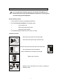
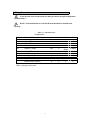
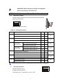
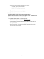
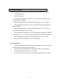
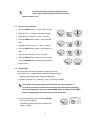
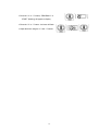
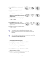
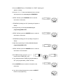
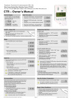
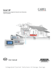
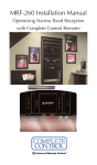
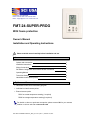
Doylestown, PA 18902 USA Phone: 215-766 1487 - Fax: 215-766 1493 Email: [email protected] - www.scillc.com FMT-24-SUPER-PROG With freeze protection Owner’s Manual Installation and Operating Instructions Please read this manual carefully before installation and use. Index Options and accessories 1 Installation Instructions 2 Wiring Connections 3 DIP Switch Configuration and External Sensor Connection 4 Operating Manual 5 Technician Settings 6 Hand held remote control (RT04) 7 1. Options and Accessories • Hand held remote control with weekly program. • Individual cool and heat set points. • External sensor option: RS01 for remote temperature sensing (1 required) RS02 for average temperature sensing (2 required) For details on where to purchase accessories, please contact SCI for your nearest location or visit our web site at www.scillc.com File: FMT-24-SUPER-PROG+FP_letter_rev1.doc | Rev. 1 | October 16 ,2007 2. Installation Instructions It is very important to find the right place to install the Flush Mount unit. Please make sure to follow all the installation instructions in order to get an accurate reading of the temperature. General points to follow: • The unit MUST be fitted into a standard electrical box. • The Unit must not be installed in the following cases: On an outside wall. When not having air draft inside. Exposed to direct sunlight. • The standard height to install this unit is 5 feet (1.5 meter). Installation procedure: Disconnect quick connector from thermostat. Connect the wires (see wiring connections #3) Reconnect the quick connector back to the thermostat. Put the thermostat in the electrical box. Set the orientation as in the picture on the right. Tighten up the 2 screws. Adapt the front frame-panel into its place, by pushing it towards the wall. 2 3. Wiring Connections If you have the super model, make sure that you choose the right configuration - please see # 4 Rc-Rh - If one transformer is in use, Rc-Rh must be shorted - (Default from Factory) Table 3.1 - Connections for all applications Terminal C Rc Rh G Function ETN 24VAC Common from transformer 24Vac RED 24Vac RED (jumpered to Rc) Fan W2 Heating 2nd Stage st W1 Y2 Y1 Heating 1 Stage / Heat Pump Cooling 2nd Stage Cooling 1st Stage T T External Sensor (option) External Sensor (option) N/A – Not Available (not in use) EMH – emergency heat mode 3 HC11 X X X X HC22 X X X X N/A X X N/A X X X X HP21 X X X X X (EMH) X N/A X X X X X X X HP32 X X X X X (EMH) X X X X X IMPORTANT! Before making any changes in the dipswitch disconnect electricity in the main board. 4. DIP Switch Configuration and External Sensor Connection 4.1 DIP Switch Location The DIP switch is located on the top of the back side of the thermostat (above the connectors). 1 2 3 4 5 6 Default DIP switch from factory Table 4.1 – DIP Switch Selection Switch 1 2 Function Internal Sensor Control 5 6 OFF X External sensor control X With Heat Pump (HP) X Without Heat Pump (HC) X In HC mode: (Switch 2 OFF) Fan Control for Electrical Heat In HP mode: (Switch 2 ON) Heat Pump in COOL mode (“O”) 3 4 ON Fan Control for Gas/Oil Heat Heat Pump in HEAT mode (“B”) X X X X 3 minutes delay for compressor X No delay X Internal Sensor Control X External sensor control X Internal Sensor Control X External sensor control X Use this table together with the illustration above showing the switch configuration. 4.2 DIP Switch Operation The DIP switch has 6 pins. 1 2 3 4 5 6 Each pin can be ON or OFF. In the picture, pin 6 - ON and pins 1,2,3,4,5 – OFF 4 Default OFF OFF OFF OFF OFF OFF ON 4.3 External sensor connection - option Important! The external sensor must be SCI type. Table 4.4 - N.TC. Sensor: Temperature ~ Resistance Characteristics Temp °C Temp °F Res. k 7.2 45 115.8 10.0 50 100.9 12.8 55 88.1 15.6 60 77.1 18.3 65 67.7 21.1 70 59.6 23.9 75 52.5 26.7 80 46.4 29.4 85 41.2 The default from factory is INTERNAL SENSOR. 1. Disconnect power to the thermostat. 2. Move DIP switches 1,5 and 6 as shown in the picture below Switch 1 - ON Switch 5 - ON Switch 6 – OFF 1 2 3 4 5 6 3. Connect the temperature sensor to T-T terminals. 4. Reconnect power to the thermostat. The wire length for the external sensor can be up to 100 feet (30 meters) with standard cable. If the distance is greater than 100 feet then it MUST be shielded type. There is a wide range of sensors for different applications, duct, rooms, etc. There are also options for averaging the temperature. For details please contact our technical line or visit our web site. 5 32.2 90 36.6 5. Operating Manual 5.1 On/Off • Press the ON button to turn the thermostat ON or OFF - the word "ON" or "OFF" will appear on display. 5.2 Set Temperature • Press the “+” or “-” buttons – “COOL” will appear on display and the set temperature for cooling will flash. • Adjust the set temperature for cooling using the “+” or “-” buttons. • Wait 3 seconds – “HEAT” will appear on display and the set temperature for heating will flash. • Adjust the set temperature for heating using the “+” or “-” buttons. • Wait until display returns to normal. 5.3 Mode, Fan speed, Auto Fan • Press the SELECT button – “UnLo” and the actual mode will appear on display. • Using the “+” and “-” buttons switch between: Cool – “Cool” will appear on display Heat – “Heat” will appear on display Emergency Heat* – “E.Heat” will appear on display Cool/Heat – auto change –over – Both “Cool” and “Heat” will appear on display Fan Only – Fan will appear on display *The Emergency Heat Mode is active only in heat-pump systems to prevent any harm to the compressor, while working in Heat mode in a very low outdoor temperature (beneath 32ºF). • Press the SELECT button again – “Fan” or “Auto Fan” will appear on display. • Using the “+” and “-” buttons switch between: Fan on – the fan will work continuously – “Fan” will appear on display. Auto fan* – the fan will work when there is demand for cool or heat – “Auto Fan” will appear on display. *Auto Fan is not available when the mode is set to “Fan Only” mode. 6 * In Heat mode, with Oil/Gas heat configuration (i.e., furnace): AUTO FAN - Fan will never be activated. FAN ON - The Fan will work continuously. • Press the ON button to return to normal display. 5.4 Lock/Unlock the thermostat button Use the Lock option to prevent users from making unwanted changes. When the thermostat is locked, the SELECT button and the “+” and “-” buttons do not work. However, the users can turn the thermostat ON or OFF. The display will alternate between “Loc” and real time clock. • Make sure both temperature set-points are different than 50ºF. • Lock the thermostat - Press and hold the SELECT button (20 seconds) until “Loc” will appear on display. • Unlock the thermostat - Press and hold the SELECT button again (20 seconds) until “UnLo” will appear on display. 7 5.5 Programming The thermostat is a 5-1-1 programmable; weekdays Monday through Friday, Saturday and Sunday both have individual programs. There are four program events per day: 1-Wake, 2-Day, 3-Return, 4-Sleep Switch between Programmable/Non Programmable configurations • Press and hold the ON button (10 seconds) – The word “Program” will either appear on display or disappear from display. When the word “Program” appears on display, the weekly program is enabled and can be modified. When the word “Program” does not appear on display, the weekly program is disabled and cannot be modified. Programming defaults from the factory. Monday to Friday 1 (Wake) 2 (Day) 3 (Return) 4 (Sleep) Start time 6:30 AM 8:00 AM 5:30 PM 10:00 PM Cool Set Point 78°F 85°F 78°F 82°F Heat Set Point 70°F 62°F 70°F 62°F Saturday 1 (Wake) 2 (Day) 3 (Return) 4 (Sleep) Start time 7:30 AM 12:30 PM 6:00 PM 11:30 PM Cool Set Point 78°F 74°F 72°F 78°F Heat Set Point 70°F 70°F 70°F 65°F Sunday 1 (Wake) 2 (Day) 3 (Return) 4 (Sleep) Start time 7:30 AM 12:30 PM 6:00 PM 11:30 PM Cool Set Point 76°F 74°F 72°F 78°F Heat Set Point 70°F 70°F 70°F 65°F • To exit the Program mode, press ON button until normal display is reached. • If no key is pressed for 30 seconds, the thermostat will return to normal display. 8 Program Chart 9 6. Technician Settings 6.1 Adjust temperature limits for cool and heat, and offset for temperature reading. • Set temperature to 50°F. • Wait until the display • Press and hold the SELECT button (5 sec.) – “COOL” and the temperature limit for cooling will appear on display. • Adjust the temperature limit for cooling (Limit Cool) using the “+” and “-“ buttons. • Press the SELECT button again – “HEAT” and the temperature limit for heating will appear on display. • Adjust the temperature limit for heating (Limit Heat) using the “+” and “-“ buttons. (Limit Heat should be higher than Limit Cool). • Press the SELECT button again – the OFFSET temperature will appear on display (a number between –6…+6). The offset is used for calibration of the measured temperature. • Adjust the Offset for ambient temperature reading using the “+” and “-“ buttons. • Press the SELECT button again to return to normal display. 6.2 Freeze Protection • When the temperature drops below 45°F, the thermostat will turn on the Heat and Fan outputs in order to protect the system from freezing. • This function will be activated when the thermostat is either in On or Off position. • The Display will alternate between ”AL” and “TEMP” • The thermostat will return to normal mode when the temperature rises above 48°F. 10 7. RT04 - Hand Held Remote Control - Option The remote control is Infrared; the remote must be pointed at the thermostat to operate. Every time you change parameters in the Remote Control, you must send it to the thermostat by pressing the ON/SEND button. 7.1 • On/Send, OFF Press the ON/SEND button to turn the thermostat ON and/or update information. • Press the OFF button to turn the thermostat OFF and update information. 7.2 • Fan Modes Press FAN button to change between: FAN ON ( ) or AUTO FAN (A). • 7.3 • Press the ON/SEND button to send information to thermostat. Modes Press MODE button to change between: COOL, HEAT, AUTO CHANGE and FAN ONLY. • Press ON/SEND button to send the information to the thermostat. 11 7.4 Temperature Set Point In Cool Mode: • Press the “+” or “-” buttons “COOL” and set temperature for cooling will flash. • Using the “+” and “-” buttons, adjust the set temperature for cooling. • Press the ON/SEND button to send the information to the thermostat. In Heat Mode: • Press the “+” or “-” buttons “HEAT” and set temperature for heating will flash. • Using the “+” and “-” buttons, adjust the set temperature for heating. • Press the ON/SEND button to send the information to the thermostat. In Auto Change-over Mode: • Press the “+” or “-” buttons “COOL” and set temperature for cooling will flash. • Using the “+” and “-” buttons, adjust the set temperature for cooling. • Press the SELECT button – “HEAT” and set temperature for heating will flash. • Using the “+” and “-” buttons, adjust the set temperature for heating. • Press the SELECT button again or Press ON/SEND button to send the information to the thermostat. 12 The thermostat keeps a minimum differential of at least 1 degree between Heat set and Cool set (Heat is always less than Cool). 7.5 Real Time Clock and Day • Press the SELECT button – “CLOCK SET” will flash. • Press the “+” or “-” buttons - the hours will flash. • Adjust the hours using the “+” and “-” buttons. • Press the SELECT button again – the minutes will flash. • Adjust the minutes using the “+” and “-” buttons. • Press the SELECT button again – the weekday will flash. • Adjust the day using the “+” and “-” buttons. • Press the SELECT button again to exit the program or Press ON/SEND button to send the information to the thermostat. 7.6 Programming Set the Program times and Temperature settings for the week: • The remote is 5-1-1 programmable: weekdays (Monday to Friday), Saturday, and Sunday can be programmed differently. • 4 program events per day: 1 (Morning), 2 (Day), 3 (Evening), 4 (Night) The program can be set away from the thermostat and can be sent later on. To send the program to the thermostat, follow the steps below without adjusting times and temperatures. Only press the ON/SEND button each time the word SEND flashes on display (point the remote control to the thermostat) • To enter programming, press and hold the SELECT button for three seconds “PROGRAM” (flashing) and the days Mon-Fri will appear on display. 13 • Press the “+” or “-” buttons, “PROGRAM 1” & “START” (flashing) will appear on display. • Press the “+” or “-” button - the hours will flash. • Adjust the hours using the “+” and “-” buttons. 14 • Press the SELECT button - the minutes will flash. • Adjust the minutes using the “+” and “-” buttons. • Press the SELECT button again – “COOL” (flashing) & the set temperature for cooling will appear on display. • Adjust the set temperature for cooling using the “+” and “-” buttons. • Press the SELECT button again – “HEAT” (flashing) & the set temperature for heating will appear on display. • Adjust the set temperature for heating using the “+” and “-” buttons. The controller keeps a safety differential of at least 1 degree between Heating set point and Cool set point (Heat is always less than Cool). After selecting the heating set point, you cannot reduce the cooling set point less than the heating set point. Continue with the rest of the program • Press the SELECT button again - “PROGRAM 2” & “START” (flashing) will appear will appear on display. • Press the “+” or “-” buttons and adjust the hours, minutes and temperature, the same way as in PROGRAM 1 • Press the SELECT button again - “PROGRAM 3” & “START” (flashing) will appear on display. • Press the “+” or “-” buttons and adjust the hours, minutes and temperature, the same way as in PROGRAM 1 15 • Press the SELECT button: “PROGRAM 4” & “START” (flashing) will appear on display. • Press the “+” or “-” buttons and adjust the hours, minutes and temperature, the same way as in PROGRAM 1 • “SEND” will flash, press ON/SEND button to send the information to thermostat. • “PROGRAM” (flashing) and “SA” (Saturday) will appear on display. • Set programming for Saturday the same way as programming MON to FRI. • “SEND” will flash; press the ON/SEND button to send the information to thermostat. • “PROGRAM” (flashing) and “SU” (Sunday) will appear in display. • Adjust the programming for Sunday the same way as programming MON to FRI. • “SEND” will flash; press the ON/SEND button to send the information to the thermostat. • The TIMER will flash; using the “+” or “-” buttons, Select TIMER ON or OFF. • If you changed between TIMER ON (programmable) or OFF (non-programmable), “SEND” will flash. • Press ON/SEND button to send the information to the thermostat. • If you did not change between them, press the SELECT button to exit programming. 16 17