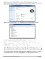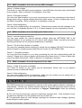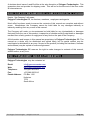
1
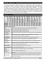
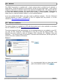
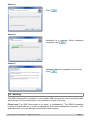
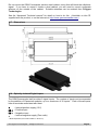
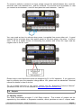
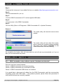
GSM Commander BASIC Manual
For the “GC” Series
V3.00
Applicable to firmware package version 6.00
Before Attempting to connect or operate this product, please read these instructions in its entirety,
especially the guarantee conditions.
TABLE OF CONTENTS
Introduction............................................................................................3
Features..................................................................................................3
Specifications.........................................................................................4
System Requirements...........................................................................4
Installation..............................................................................................4
Power Supply.......................................................................................................4
USB Port..............................................................................................................5
SIM Card..............................................................................................................5
Antenna...............................................................................................................6
Software Installation............................................................................................6
Mounting..............................................................................................................7
Dimensions..........................................................................................................8
Optically-Isolated Digital Inputs...........................................................................8
Outputs................................................................................................................9
Temperature Sensor..........................................................................................10
Analog Input.......................................................................................................11
Battery Input......................................................................................................11
Expansion..........................................................................................................12
Status LEDs.......................................................................................................13
Testing the GSM Commander...........................................................................13
Configuration........................................................................................14
Configuration via PC..........................................................................................14
Behaviour Statements.......................................................................................15
Configuration via SMS.......................................................................................17
Timed Operations.................................................................................18
Prepaid Airtime Voucher Loading......................................................18
Application Examples..........................................................................19
Example 1: Periodic message...........................................................................19
Example 2: Monitor alarm..................................................................................19
Example 3: Control an appliance.......................................................................20
Example 4: Gate / garage door opener.............................................................20
Example 5: Contact to Contact relay ...............................................................21
Firmware Updates................................................................................22
Troubleshooting...................................................................................22
Guarantee.............................................................................................24
Important Notice (Disclaimer / Copyright).........................................25
Manufacturer Contact Details.............................................................25
© Polygon Technologies. All rights reserved
Page 2
1. INTRODUCTION
The Polygon Technologies GSM Commander is a state-of-the-art, highly configurable and
versatile SMS controller. It contains a quad-band integrated GSM cellular engine that allows it
to connect to any cellular network to send and receive SMS messages. The GSM
Commander can be used to monitor inputs, measure analogue voltages, and remotely control
outputs. The GSM Commander is configured using a software program that provides an easy
wizard interface. The GSM Commander connects to a PC via USB for configuration, after
which it may be disconnected from the PC for standalone operation. Some setup operations
can also be performed by sending simple SMS messages.
Model
Onboard Inputs
Onboard Outputs
Expandable
Inputs/Outputs
Max Number of
Statements
Max number of
Phone Numbers
Max number of
Messages
Max Length of
Messages
Setup Memory
0-100deg Temp
probes supported
0-10v Analog
Inputs
Battery / Power
Monitor
Configuration
Via USB
DTMF Decoder
SIM Card Slots
2. FEATURES
GC0321
2
2
12/12
32
250
64
128
2kb
2
1
YES
YES
NO
Single
GC0641
2
2
22/22
64
512
128
128
4kb
2
1
YES
YES
YES
Single
GC1281
2
2
32/32
128
512
128
128
8kb
2
1
YES
YES
YES
Dual
Matrix Feature Descriptions
Model
The code used to define between the various units functionality and capabilities
Onboard Inputs
The number of inputs provided on the base unit itself
Onboard Outputs
The number of outputs provided on the base unit itself
Expandable
Inputs/Outputs
The maximum total number of Inputs/Outputs that can be expanded to by fitting expansion
units
Max Number of
Statements
A measure of the amount of complexity that can be programmed into the unit. Each
statement is of the form IF <ABC happens> THEN <do something>, such as IF Input 1 goes
Active, THEN send “Generator Tripped” to “0831231234”
Max Number of
Phone Numbers
The maximum total number of phone numbers that can be programmed into the unit
Max Number of
Messages
The maximum total number of messages that can be programmed into the unit
Max Number of
Statements
The maximum total number of behaviour statements that can be programmed into the unit
Setup Memory
The amount of memory that is available for setup. - This is a measure of how much
information the setup can contain. Each 1kb of memory can store up to 146 Telephone
numbers, or 56 Messages(16 characters each)
0-100deg Temp
Probes supported
The number of temperature probes the base unit can accept
0-10v Analog Inputs The number of analog Inputs available
Battery / Power
Monitor
The ability to detect power failures and monitor a connected battery.
Configuration
Via USB
The unit is configured via software from a PC.
DTMF Decoder
if YES, the unit is able to recognize (and respond to) key presses on a remote phone during
a voice call.
SIM Card Slots
If Single, the unit has only a single SIMcard slot. If the SIMcard in that slot becomes faulty
or the associated network goes down, the unit loses communication ability. If Dual, the unit
can switch over to a secondary SIMcard if it detects problems on the primary SIMcard, thus
greatly enhancing reliability.
© Polygon Technologies. All rights reserved
Page 3
3. SPECIFICATIONS
Base Unit Technical Specifications:
Digital Inputs:
Digital Outputs:
Opto-isolated. Inputs draw 10-30mA, depending on the voltage.
Can accept DC signals of any type, including:
- Dry Contacts
- Open Collector (NPN)
- Open Collector (PNP)
- DC Voltage (5-18V)
SPDT Relays
Rating: 8Amp DC (10-48V) ) OR 4Amp AC (110-400V) (non inductive loads)
Current Consumption:
~60mA at Idle (no inputs or outputs active)
Power Supply:
10-24V DC via DC Jack or Screw Terminal
It is advised that the base unit be powered from its own dedicated supply in
industrial applications.
Operating Temperature:
-10 to +60 °C
Storage Temperature:
-20 to +85 °C
Dimensions:
146,2 x 86,2 x 27mm
More comprehensive specifications are available in the “Advanced Technical Manual”
(Available on the CD supplied with the product, or on the Internet at
http://www.gsmcommander.com)
4. SYSTEM REQUIREMENTS
The setup software requires a PC with the following specifications:
Operating system
Win2000 / WinXP / Vista / Win7
Computer Architecture
Pentium 2 or higher IBM compatible PC
Disk space
2MB
Ports
1 x free USB port
5. INSTALLATION
5.1. Power Supply
The GSM Commander has a 2.1mm DC jack connector where a power supply must be
connected. The power supply should have the following specifications:
•
•
•
Output Voltage: 12V nominal
Output Current: 0.5A
Polarity:
A suitable power supply is supplied with the retail product.
Please Note: It is advised to use a 14V Switching Power Supply if more than one Expansion
Unit is connected to the GSM Commander.
© Polygon Technologies. All rights reserved
Page 4
In industrial applications, it is advised that the GSM Commander be installed into its own
metal housing and be powered from a separate power supply. (As opposed to sharing one
with other equipment).
Please Note: While the GSM Commander has fairly rugged internal power supply circuitry, no
special provision for lightning protection is made. If the GSM Commander is used in an area
that is prone to thunderstorms, it is advisable to use a commercially available lightning
suppressor (The same applies to inputs or outputs that are connected to wires longer than 2
or 3 meters). The guarantee does not cover damage resulting from lightning strikes! The GSM
Commander can operate reliably from voltages in the range of 10 to 24V DC.
5.2. USB Port
The GSM Commander provides a USB port that connects to a PC using the supplied USB
cable. This allows the PC to configure the unit.
5.3. SIM Card
The GSM Commander accepts a standard GSM SIM card from any network. The SIM card
may be prepaid or on contract. If the SIM Card is purchased as part of a prepaid plan, ensure
than the card is loaded with sufficient airtime.
WARNING: DO NOT Insert or remove the SIM card while the GSM Commander is powered!!
Note that airtime will decrease with every SMS that is sent from the unit. The unit can
automatically detect if the airtime is running low. It is user's responsibility to make sure than
the airtime is topped up. See your network's documentation on how to purchase and load
airtime.
The SIM card is fitted into the back of the unit, as indicated by the legend on the enclosure.
The SIM card will click into place. The SIM card is removed simply by pressing against it. The
card will pop out with a “click” sound, ready to be completely removed.
Before you install your SIM Card:
•
•
•
Install the SIM card into a normal cellular phone
Verify that there is no SIM PIN enabled (The phone must not ask for a PIN when switched
on with this SIM card inside) If the phone does request a PIN, you need to enter the
correct pin so that the phone can start, and then disable the SIM Card PIN. See your
cellphone documentation on how this can be done.
Verify that you are able to send an SMS message.
The SIM card will now work with the GSM Commander.
Please Note: If you are using a prepaid SIM card, be aware that if the SIM card has not
produced a billable event on the network for a long period of time (typically 3 months), the
card will be de-activated by the network, and the SIM card then becomes useless. It is
strongly recommended that you configure the GSM Commander to send you an SMS every
now and then (once or twice a week) so that your SIM card remains active on the network.
The GSM Commander can ONLY check the airtime of a PREPAID SIM card.
© Polygon Technologies. All rights reserved
Page 5
5.4. Antenna
The GSM Commander is supplied with a basic antenna that is suitable for all networks in
South Africa. Screw the antenna to its connector on the unit (only finger-tight). Verify using a
cellphone, that there is sufficient signal at the proposed installation site. On a phone with a 4
or 5-bar signal strength indicator, you should have at least 1-2 bars of signal. If the signal is
too weak, the GSM Commander may have trouble sending or receiving SMS messages. In
these cases, try and find a better location, or use a special antenna.
If you are outside South Africa, you may require a different antenna. See the “Advanced
Technical Manual” for detail. (Available on the CD supplied with the product, or on the
Internet at: http://www.gsmcommander.com/)
5.5. Software Installation
The latest software is supplied on a CD with the product and is also available to download
from our website for free at: http://www.gsmcommander.com/
The setup program will start automatically, or if the autorun feature is not enabled on your PC,
you may run the “setup.exe” executable file on the CD to start the setup process. The
software has been tested to work on Windows 2000, Windows XP, Windows Vista and
Windows 7. The setup process for Windows 7 has been documented here, but the process is
similar in the other versions of Windows.
Screen 1:
Click
Screen 2:
It is recommended that you leave the install
path at the default location. Click
© Polygon Technologies. All rights reserved
Page 6
Screen 3:
Click
Screen 4:
Installation is in progress. When installation
completes, click
Screen 5:
Installation has been completed successfully.
Click
5.6. Mounting
The GSM Commander is housed in a very durable ABS casing which has 4 protruding tabs,
which allows it to be mounted firmly to any surface by means of a screw.
Please note: The GSM Commander is not water- or weatherproof. The GSM Commander
must be mounted indoors, or inside an appropriate IP65-rated weatherproof enclosure. The
guarantee does not cover damage resulting from water ingress!
© Polygon Technologies. All rights reserved
Page 7
Do not mount the GSM Commander inside a steel cabinet, since this will block the cellphone
signal. If you have to mount it inside a steel cabinet, you will need to mount a separate
antenna on the outside of the cabinet. Suitable antennas can be ordered from Polygon
Technologies.
See the “Advanced Technical manual” for detail on how to do this. (Available on the CD
supplied with the product, or on the Internet at: http://www.gsmcommander.com)
5.7. Dimensions
5.8. Optically-Isolated Digital Inputs
The GSM Commander itself provides 2 signal inputs. The number of inputs can be expanded
by the addition of Expansion modules, up to a maximum of 32 inputs*. Each of these inputs
have 4 terminals associated with them:
+
– Internal positive supply (12V)
IN + – Positive input
IN – – Negative input
–
– Internal negative supply (Zero volts)
* Model Dependent (See Feature Matrix in Section 2)
© Polygon Technologies. All rights reserved
Page 8
To connect a switch or contact to an input, simply connect the switch between the + and IN+
terminals, and a wire between the – and IN– terminals. The reverse is just as suitable, i.e. that
you connect a wire between + and IN+ and place the switch between – and IN–.
You may need an input to activate when power is supplied from some other unit. A good
example will be a burglar alarm that applies power to the wires going to the siren. In such a
case, it will be a simple matter of connecting the positive wire to the IN+ input, and the
negative wire to the IN– input.
Please keep in mind that these inputs are designed for 5V to 18V operation. If you require an
input to activate upon the presence voltage above 18V, please see the advanced Technical
manual for details on how to do this.
For an in-depth overview of the inputs, please see the “Advanced Technical Manual”.
(Available on the CD, or on the Internet at http://www.gsmcommander.com)
5.9. Outputs
2 x 8A Relay output
The GSM Commander provides 2 x 8A Relay outputs. The number of outputs can be
expanded by the addition of Expansion modules, which provides an extra 5 outputs each.
© Polygon Technologies. All rights reserved
Page 9
Each of these inputs each have 3 terminals associated with them:
COM – Common Terminal
N/C – Normally Closed Terminal
N/O – Normally Open Terminal
When the output is off, the COM and N/C terminals will be internally connected to each other.
When the output is on, the COM and N/O terminals will be internally connected to each other.
Note that there are small LED indicators next to the output terminals, that will show if the
output is ON or OFF. (if the LED is on, then the output is also on) In the picture below, the
output is connected so that the lamp will light up when the output is on.
This output can be used to control devices and appliances, and is rated for 8A DC. It may be
used to control most types of electrical loads, excluding AC motors above 500W.
Here are some examples of things you CAN directly switch on and off using the outputs on the
GSM Commander:
•
•
Gate motors and any other motor less than 500W
Mains Lights (energy savers, incandescents, halogens) (maximum 750W)
Here are some examples of things that you can NOT directly switch on and off using the
outputs on the GSM Commander:
•
•
Ovens, Heaters, kettles
Pumps and motors above 500W
Keep in mind that if required, the above loads can easily be switched on and off using an
externally connected relay or contactor.
5.10. Temperature Sensor
One can connect 2 temperature sensors to the GSM Commander (at the expansion port via a
temperature interface module) to measure temperature and allow the GSM commander to
perform certain tasks if the temperature falls above or below a certain point. The sensor
provides an accuracy of 1°C, and can only measure temperatures between 0-100°C.
The temperature sensor (with 2m or 4m lead) and temperature interface is available from
Polygon Technologies. (Part no: GT001-1 OR GT001-2 and GT002).
© Polygon Technologies. All rights reserved
Page 10
5.11. Analog Input
The GSM Commander provides a single 0-10V analog input, which can be used to measure
incoming voltages from sensor devices. Using an appropriate resistor, one can also connect
4-20mA sources to the GSM Commander.
What makes this input so special, is that the GSM Commander can interpret the analog value
on your behalf. It is perhaps the best to explain this at the hand of a good example.
Suppose you have a water tank, with a level sensor that is connected to the analog input of
the GSM Commander. The sensor is such, that when the tank is empty, the voltage is 1.2v,
and when the tank is full, the voltage is 7.8v. The configuration software allows you to request
the current reading in a scaled format. You would thus tell the software that 7.8v should
correspond to 5000 litres, and 1.2v should correspond to 0 litres, and leave the rest of the
calculations to the GSM Commander.You can now receive a message from the Commander,
detailing the actual contents of the tank in litres, instead of just a raw value. (Which you would
otherwise have had to convert back to “real” numbers yourself).
Please note that this feature assumes a
linear relationship between the input
voltage and the desired output units.
Thus, this will not work very well for a
cylindrical tank that is mounted on its
side, as the voltage from the level
sensor is not linearly proportional to the
actual contents of the tank.
The user is also able to define the
message to precede, and the message
to follow the analog value.
Please Note: The input is NOT
isolated, and must be used with care.
See the “Advanced Technical manual”
for more detail. (Available on the CD supplied with the product, or on the Internet at:
http://www.gsmcommander.com)
5.12. Battery Input
The GSM Commander provides connections for an external rechargeable 12v battery. The
battery is continuously trickle-charged from the GSM Commander, as long as there is power
supplied to the power connector of the GSM Commander .
In the case of a power failure, the GSM Commander can continue operating from the external
battery. The unit can be configured to perform certain tasks (like sending a warning SMS) if
the battery voltage falls below a certain point, and can also perform tasks in the case of a
power failure. (Like sending an SMS and switching on emergency lighting)
Suitable batteries are available from Polygon Technologies.
© Polygon Technologies. All rights reserved
Page 11
5.13. Expansion
The GSM Commander supports comprehensive expansion by means of the GSM
Commander Expansion unit, which provides an additional 5 inputs and 5 outputs similar to the
ones found on the GSM Commander itself.
A total of 6 Expansion units may be daisy chained to provide a maximum of 30 outputs and
30 inputs* in addition to those on the GSM Commander itself.
12V input on Expansion
Each Expansion unit has a 12V input, so that it could also be powered by a separate power
supply. Applying power to this input is optional. The expansion unit can draw power via the
interface ribbon cable, but under certain conditions it is better to supply a separate 12V source
to the expansion unit.
These conditions are:
➢ When the ribbon cable run becomes very long (>5m)
➢ If you are going to connect more than one expansion unit
➢ If you expect to draw power from the input on the Expansion unit
➢ If you expect all inputs and outputs on the expansion to likely be active at once
The Expansion unit will automatically detect if power is applied at its 12V power port. If power
is detected, it will stop drawing power via the ribbon cable, and will draw all its power directly
from the 12V input.
Interface Ribbon cable
Supplied with each Expansion unit is a short (10cm) ribbon cable for interface purposes, but
this ribbon can also be very long. We have tested up to 10m, but we generally recommend a
maximum cable run of 7-8m. Please contact us if you need a longer ribbon cable.
The ribbon cable connectors are mounted such that pin 1 on the one end connects to pin 10
on the other, Pin 2 connects to pin 9 etc.
It is important to connect the Expansion port on the GSM Commander to the IN connection on
the expansion unit. An additional expansion unit must be connected with its IN connection to
the OUT connection of the “upstream” Expansion unit.
* Model Dependent (See Feature Matrix in Section 2)
© Polygon Technologies. All rights reserved
Page 12
5.14. Status LEDs
The GSM Commander has 2 LEDs to show the current status of the GSM Commander. The
red LED, labeled “GSM”, shows the status of the internal GSM cellular engine, while the green
LED, labeled “STATUS”, shows the status of the GSM Commander as a whole.
The following table shows how one can determine the current status:
GREEN LED (STATUS)
➢ Solid On
: Busy Booting
➢
on for 500ms, off for 500ms (slow flash)
: All OK
➢
on for 200ms, off for 200ms (fast flash)
: Airtime running low
➢
on for 10ms, off for 500ms (2 short flashes per second)
: Signal is low
➢
on for 50ms, off for 50ms (very fast flash)
: Problem with GSM engine
➢
on for 100ms, off for 500ms, on for 100ms, off for 500ms,
on for 500ms, off for 500ms (2 short and 1 long flash)
: Setup is corrupt
RED LED (GSM)
➢ OFF
➢ on for 600ms, off for 600ms (1 flash per second)
: GSM engine OFF
: GSM engine not finding network
➢
on for 75ms, off for 3000ms (1 flash every 3 seconds)
: GSM engine registered OK
5.15. Testing the GSM Commander
5.15.1. Status Request
The GSM Commander (even with a blank configuration) has a built-in test feature. If the GSM
Commander receives “TEST GSMC” as an SMS message, it will reply to the number that
sent the message, with the following text:
DT=01/01/2010-12:00:00
Sig=68%
FW=6.01
SN=100641-02435
Airt=35
Power=On
< Indicates current date & time of the GSM Commander
< Indicates the received signal strength
< Indicates the firmware version
< Indicates the serial number
< Indicates the amount of airtime remaining
< Indicates status of mains power
Please Note: The airtime remaining will be displayed as “Airt=???” if airtime checking has
been disabled or the incorrect network operator has been chosen in the current setup.
© Polygon Technologies. All rights reserved
Page 13
6. CONFIGURATION
6.1. Configuration via PC
The following is required to configure the GSM Commander:
➢
A PC running Windows XP / Vista / Windows 7
➢
Setup utility installed on the PC (Available on the CD supplied with the product)
➢
USB cable (Provided)
➢
Power supply (See 5.1)
➢
Antenna (See 5.4)
➢
SIM card(s) (See 5.3)
Please note: The GSM Commander will startup immediately if no SIM card is inserted, but
there would be no GSM functionality, which means none of the GSM features will work.
Follow these steps:
Step 1:
Insert SIM card(s) into unit
Step 2:
Connect GSM Commander to PC via the supplied USB cable
Step 3:
Connect power to the GSM Commander
Step 4:
Run the Utility (Start > All Programs>GSM Commander V6 > Configure GSM Commander)
The software will show this screen
when started. Here you can select
whether you would like to start a new
setup (via the Wizard), or whether you
would prefer opening an existing setup
from a file on your PC, or retrieve the
setup
currently
on
the
GSM
Commander
During the setup process, the user will specify a cellphone number for the administrator. (The
first number in the list of cellphone numbers) This number will be used for administrative
purposes as explained in section 6.2
© Polygon Technologies. All rights reserved
Page 14
6.2. Behaviour Statements
The GSM Commander is configured by defining a number of behaviour statements. Each
statement takes the form of an IF-THEN pair. You are thus able to select certain trigger
conditions that will cause desired actions to be performed. Any combination of IF and THEN
parts can be assembled into complete statements using the configuration software. The GSM
Commander can accept up to 128 separate behaviour statements, depending on the model .
One is also able to select time and input/output* constraints for any IF-THEN statement pair,
so that a statement will only be allowed to trigger at certain times of day, and on certain days
of the week or only if certain input/output conditions are met.
6.2.1. Supported IF Conditions
➢
IF a Message is Received
•
•
•
•
➢
From Any number Containing Anything or a Specific Message
From Any number appearing in the list Containing Anything or a Specific Message
From a Specific number in the list Containing Anything or a Specific Message
From Serial port Containing a Specific Message (“Serial Port” refers to the connection labeled “RS232”)
IF Voice Call is Received (Call Options : Hang up or Stay on)
• From Any number
• From Any number appearing in the list
• From a Specific number in the list
➢
IF Input
•
•
•
•
•
➢
IF Logic Expression (limited to the monitoring of 16 inputs and 16 outputs)
•
•
•
•
➢
Goes Active
Goes Inactive
Changes State
Goes Active, remaining Active for longer than
Goes Inactive, remaining Inactive for longer than
If ALL of the selected signals are active
If ANY of the selected signals are active
If NOT all the selected signals are active
If NONE of the selected signals are active
IF Variable*
• Check if Above Threshold
• Check if Below Threshold
➢
➢
IF DTMF Tone is Received During Voice Call*
IF Analog Input
•
•
•
•
➢
IF Temperature
•
•
•
•
➢
➢
➢
➢
➢
➢
➢
Check if Above Threshold
Check if Below Threshold
Check if Inside Window
Check if Outside Window
Check if Above Threshold
Check if Below Threshold
Check if Inside Window
Check if Outside Window
IF Power Failure Detected
IF Power Restored
IF Battery Voltage < X
IF SIM Failure Detected**
IF Prepaid Airtime < X
IF Time Elapsed > X
IF Statement X has NOT Triggered in a Certain Period
© Polygon Technologies. All rights reserved
Page 15
➢
IF Date/Time is X
• Everyday
• Day-of-Week
• Specific Date Range
➢
➢
IF Startup
IF GSM Signal Strength
• Above X
• Below X
➢
IF Statement X Triggers
6.2.2. Supported THEN Actions
➢
THEN Change Output
•
•
•
•
•
➢
THEN Send Message
•
•
•
•
•
•
•
•
•
•
•
•
•
➢
Activate for a time
Activate for a time – Pause – Activate for a time
Activate (Leave Activated)
De-Activate (Leave De-Activated)
Change State
Plain Message
Input/Output Status
Temperature (Probe A)
Temperature (Probe B)
Temperature (Probe A and B)
Temperature (Avg of Probe A and B)
General Status
Power Status
Airtime Status
Analog Input Status (Able to define own scale and unit)
Global Input Status
Please Call Me
Variable Value Message*
THEN Place Voice Call
• Specify time to ring
• Specify number of calls to make
• Specify time between calls in minutes
➢
➢
➢
➢
Enable/Disable Statements
Enable/Disable ALL SMS sending
Set Multiple Outputs to Pattern
Change Variable*
•
•
•
•
➢
Increment
Decrement
Clear
Set to Value
Then Change Active SIM card**
• Change to SIM 1
• Change to SIM 2
• Toggle active SIM
Please note: * Only available on the 641 and 1281 models
** Only available on the 1281 model
For an in-depth discussion on all the trigger conditions, See the “Advanced Technical Manual” for
detail. (Available on the CD supplied with the product, or on the Internet at:
http://www.gsmcommander.com)
© Polygon Technologies. All rights reserved
Page 16
6.3. Configuration via SMS
The GSM commander provides functionality to provide some configuration changes to be
done via SMS message (from the administrator number only). Note that the unit cannot be
setup by SMS only. A PC is still required to perform the initial setup. Thereafter, some simple
changes to the setup may be done using SMS messages. Please note: The Configuration
SMS is NOT case sensitive.
The following operations can be performed via SMS message:
➢ Set Administrator number
➢ Clear Administrator number
➢ Check Administrator number
➢ Check Airtime
➢ Add a number to the list
➢ Remove a number from the list
6.3.1. Set Administrator number
This command can ONLY be sent from the administrator number(if one exists), otherwise it
can be sent from any number .
ADMIN SETADM 0831234567
This will store “0831234567” as the new administrator number. The GSM Commander will
reply with a confirmation message.
6.3.2. Clear Administrator number
This command can ONLY be sent from the administrator number.
ADMIN CLRADM
This will remove the current administrator number. The GSM Commander will reply with a
confirmation message.
6.3.3. Check Administrator number
This command can be sent from ANY number, and is useful to determine which number is the
correct administrator number.
ADMIN?
The GSM Commander will reply with the administrator number in the reply message.
6.3.4. Check Airtime
This command can be sent from ANY number, and is useful to check the amount of airtime
remaining on the unit. To check airtime, you must send:
ATCHECK
The GSM Commander will reply with a message detailing the current airtime.
© Polygon Technologies. All rights reserved
Page 17
6.3.5. Add a Number to the list*
This command can only be sent from the administrator number. To add a number to the list,
the administrator must send:
ADMIN ADDN 0831234567
The GSM Commander will reply with a confirmation message.
6.3.6. Remove a Number from the list*
This command can only be sent from the administrator number.
(+27831234567) from the list, the administrator must send:
To remove a number
ADMIN REMN 0831234567
The GSM Commander will reply with a confirmation message.
*Please Note: The value predefined by the user via the software under the “Numbers Tab” (as
illustrated below), will determine how many numbers are able to be added and removed by
means of SMS.
7. TIMED OPERATIONS
The GSM Commander supports time constraints, which can be setup for any statement. Time
constraints will prevent a statement from triggering outside of the preselected times and days
of the week. The GSM Commander can also be configured to trigger a statement at a certain
time on a certain date or group of days.
The current time and date can be set in one of two ways, either by SMS or by clicking on the
tab “Set to PC time” in the software interface under the “Status Tab”.
By means of SMS you would send a special SMS message to the GSM Commander,
containing the text: “SETTIME”. The cellular network supplies the time and date with any
message that is sent, and the GSM Commander sets its own time according to this.
Please Note: The GSM Commander will lose its time if power is removed, and no battery
backup is used. Upon power-up, if any statement has a time constraint enabled, the GSM
Commander will automatically send a message to the first number in the list, requesting a
“SETTIME” reply so that it can set its time.
The GSM Commander will not allow any time constrained statement to trigger if the time has
not yet been set.
8. PREPAID AIRTIME VOUCHER LOADING
If using a prepaid SIM card, it is recommended that prepaid airtime be topped up via an ATM
or via your bank's Internet banking portal. If your network or bank does not support this, you
can purchase a normal airtime voucher and remotely send the voucher number to the GSM
Commander, which will in turn send the voucher number to the network to top up the airtime.
© Polygon Technologies. All rights reserved
Page 18
Your airtime top-up voucher is typically a long number, and when using this voucher number
with a normal cellphone, you typically need to frame this number by some preceding and
appending text.
For example, with MTN in South Africa, you need to send:
“*141*0000000000000#”
where the “141” is network-dependent, and the 0000000000000 is the voucher number.
This detail is typically provided on the voucher slip.
To send a voucher to the GSM Commander, you simply send it an SMS of the form :
SENDUSD:*141*000000000000# ( from any number)
where 000000000000 is the voucher number.
The GSM Commander will receive this and post the voucher number along to the network.
After a few minutes you can verify if the airtime has been topped up by sending an SMS
containing ATCHECK to the GSM Commander. The device will reply with the current airtime.
9. APPLICATION EXAMPLES
9.1. Example 1: Periodic message
In this example we discuss the use of periodic messages to ensure that your GSM
Commander produces a billable event on the network on a regular basis. If you use a prepaid
SIM card, the network will de-activate your SIM-card if it has not been used for some time
(See Section 5.3).
We will create two behaviour statements, The first will send a free-of-charge “please call me”
message every day, to give you a confirmation that the unit is up and running. The second
will send a Status SMS to your cellphone every 3 days to ensure that the SIM-card remains
active on the network. (The status message also gives you the total airtime remaining)
Configuration:
Using the setup software, we create a behaviour statement that will read as follows:
IF Time Elapsed > 1440 Minutes (24 Hrs)
THEN Send “Please call me” to +27821231234
A second behaviour statement is created, that reads:
IF Time Elapsed > 4320 Minutes (72 Hrs)
THEN Send Status Message to +27821231234
The GSM Commander will count “Time elapsed” as the amount of time that has elapsed since
the last time this statement has triggered, or since the unit has started up.
9.2. Example 2: Monitor alarm
In this example we need to monitor an alarm system, and in the case of an alarm, the GSM
Commander must make a voice call and send a message to one or more numbers.
© Polygon Technologies. All rights reserved
Page 19
Hardware:
We connect the alarm output (12V signal that drives the siren) to one of our inputs as
described in section 5.8. The positive wire from the alarm panel is connected to the IN+
terminal, and the negative wire is connected to IN-.
Configuration:
Using the setup software, we create a behaviour statement that will read as follows:
IF Input 1 Goes Active
THEN Place voice call to +27821231234
We create a second behaviour statement that will read as follows:
IF Input 1 Goes Active
THEN Send “Alarm triggered!” via SMS to +27821231234; +27843214321
The first statement will cause a voice call to be placed to +27821231234 in the event of an
alarm. The second statement will cause a notification SMS to be sent to both +27821231234
and +27843214321.
This is an example of how the GSM Commander can have multiple actions triggered by a
single event (in this case, an input becoming active). Note that the voice call will not “say”
anything when the call is answered. One will typically use Caller ID to identify the GSM
commander number, and this will be enough to let you know that there is something wrong at
home.
9.3. Example 3: Control an appliance
In this example we need to switch a 220V light bulb on or off via a suitable SMS message
from a specific number listed on the GSM Commander.
Hardware:
We connect light bulb to a 220V power source via the output 1 contact on the GSM
commander, exactly as described in section 5.9
Configuration:
Using the setup software, we create a behaviour statement that will read as follows:
IF Message is received, containing “Lights on” from 0821231234 , THEN Activate Output 1.
We create a second behaviour statement that will read as follows:
IF Message is received, containing “Lights off” from 0821231234, THEN Deactivate Output 1.
9.4. Example 4: Gate / garage door opener
In this example we need to open a gate in response to a missed call from any number in a list
of accepted numbers. This is an ideal method to control a communal gate in a complex.
Hardware:
Many gate openers require a pulse to open, and second pulse to close. We will use the
output of the GSM commander to supply this pulse at the position where the open/close
switch is normally connected to the opener.
© Polygon Technologies. All rights reserved
Page 20
Configuration:
Using the setup software, we create a behaviour statement that will read as follows:
IF a Voice Call is received from any listed number,
THEN Activate Output 1 for 1 Sec, Pause for 20 Sec, Activate again for 1 Sec.
9.5. Example 5: Contact to Contact relay
In a few instances it may be necessary to transmit the status of a contact to a remote point.
Let us use an alarm as example. If the alarm at your home sounds, you may want a warning
light to switch on in a remote location and a voice call to be placed to a specified number.
For this example, we will use two GSM commander units, one at the local alarm system, and
another at the remote location.
Local GSM Commander Hardware: We connect the alarm output (12V signal that drives the
siren) to one of our inputs as described in section 5.8. The positive wire from the alarm panel
is connected to the IN+ terminal, and the negative wire is connected to IN-.
Local GSM Commander Configuration:
Using the setup software, we create the following behaviour statements:
IF Input Goes Active
THEN send “alarm on” via SMS to +27833341234
IF Input 1 Goes Active
THEN Place Voice Call to +27821121323
IF Input 1 Goes inactive
THEN send “alarm off” via SMS to +27833341234
The above 3 statements detail two actions to trigger in the event that the input goes active.
One is an SMS message to the remote unit, and another is a voice call to a cellphone. In the
above statements, +27833341234 is the number of the GSM commander at the remote
location.
Remote GSM Commander hardware:
We use a second GSM commander unit at the remote location. Here we connect the warning
light to output 1 of the GSM Commander so that if the relay is activated, the warning light will
turn on. (exactly as described in section 5.9)
Remote GSM Commander configuration:
The configuration of the remote unit will be similar to example 2 (control an appliance). Using
the setup software, we create the following behaviour statements:
IF Message is received containing “alarm on”, from number +27831112222,
THEN Activate Output 1.
IF Message is received containing “alarm off”, from number +27831112222,
THEN Deactivate Output 1.
In the above statements, +27831112222 is the number of the local GSM commander.
© Polygon Technologies. All rights reserved
Page 21
10. FIRMWARE UPDATES
Step 1:
Download the “setup.exe” executable file from our website (http://www.gsmcommander.com)
Step 2:
Run the executable file (See 5.5)
Step 3:
Connect GSM Commander to PC via the supplied USB cable
Step 4:
Connect power to the GSM Commander
Step 5:
Run the Utility (Start > All Programs > GSM Commander V6 > Update Firmware)
Screen 1:
The loader utility will show this screen when
started.
Screen 2:
The loader utility will now show this screen,
which means the firmware is being updated.
The green LED, labeled “STATUS” on the
GSM Commander, will start flashing.
On completion the loader utility will close and the unit will start up automatically or if you so
wish you can disconnect the power.
11. TROUBLESHOOTING
11.1. GSM Commander setup software reports “Hardware not detected”
This error can have several causes:
Cause 1: GSM Commander not powered properly
Cause 2: GSM Commander not connected via USB
Cause 3: GSM Commander USB drivers not installed.
It is a good idea to disconnect all cables from the GSM Commander, and then reconnecting
everything (power and USB cable). If the problem persists, please follow this procedure to
verify that the drivers are correctly installed:
© Polygon Technologies. All rights reserved
Page 22
Step 1: Connect USB Cable to GSM Commander (ONLY USB, and not the Power)
Press “Windows key” and “Pause” simultaneously on your computer keyboard. This will bring
up the “System properties” window as below:
Step 2: Select “Device Manager”. This will open the device manager window as below:
Double Click on “Universal Serial Bus(USB) controllers”
In the list of USB controllers, you should see an item called “GSM Commander”.
If this item is not present, the drivers are not installed correctly. To install your drivers, go to
C:\Program Files\GSMCommander V6\drivers\drv_install and run
“GSMC_USBXpressInstaller.exe” or run “Reinstall drivers” (Start>All Programs>GSM Commander
V6>Reinstall drivers). This will install your drivers.
11.2. GSM Commander setup software reports “Could not initialize the internal
module”(Also shown by the green Status LED flickering at a vary fast rate)
This is a problem state, and may be caused by a supply voltage that is too low. (The supply
must be in the range 10..24V). If this problem persists, the GSM Commander is faulty.
© Polygon Technologies. All rights reserved
Page 23
11.3. GSM Commander does not send any SMS messages.
Cause 1: Airtime problem
The airtime on your SIM card may be depleted, or the SIM card may have been de-activated
by the network. Refer to Section 5.3 (Installation: Sim Card)
Cause 2: Reception problem
You may have bad reception in your area, preventing the unit from connecting to the network.
Please check using a regular cellular phone that there shows 1-2 bars of signal right next to
the GSM Commander. Refer to Section 5.4 (Installation: Antenna)
Cause 3: Bad configuration
You may have configured the unit incorrectly. Please send a status request message to the
unit, and see if it responds (Section 5.15.1). If it does respond, the unit is operating correctly.
11.4. GSM Commander does not display the Airtime value
Cause 1: Incorrect operator selection
You may have chosen the incorrect operator settings under the “SETTINGS TAB” in the
software interface. If your operator is not in the list, then choose “Other” and define the airtime
checking and please call me numbers respectively (If available).
Cause 2: “Do Not Check Airtime” is enabled
You may have disabled airtime checking by ticking the box labeled “DO NOT Check Airtime”
which is located in “Supplementary Data Services” under the “SETTINGS TAB”.
Cause 3 : Reception problem
You may have bad reception in your area, preventing the unit from communicating with the
network. Please check using a regular cellular phone that there shows 1-2 bars of signal right
next to the GSM Commander. Refer to Section 5.4 (Installation: Antenna)
11.5. GSM Commander does not respond to Voice Calls
Cause 1: Caller ID on phone is disabled
Your Caller ID feature on your phone may be deactivated. Please refer to your phone's
manual on how to enable this feature.
Cause 2: Bad configuration
You may have configured the unit incorrectly. Make sure the number you are calling from is
stored in the “Numbers List” on the GSM Commander.
12. GUARANTEE
The GSM Commander is guaranteed for a period of 24 months against defects in materials or
workmanship. Should your product become defective during the guarantee period it will be
repaired or replaced at the sole discretion of Polygon Technologies under the following
conditions:
A: The unit must not have been opened or otherwise tampered with. If the enclosure of any
unit has been opened at all, the guarantee will be null and void.
B: The guarantee does not cover damage resulting from excessive input voltages, lightning,
power surges or water ingress.
© Polygon Technologies. All rights reserved
Page 24
A decision about issues A and B will be at the sole discretion of Polygon Technologies. This
guarantee does not provide for shipping costs. This will be for the account of the user under
all circumstances.
13. IMPORTANT NOTICE (DISCLAIMER / COPYRIGHT)
Herein, “the Company” will mean:
Polygon Technologies CC, its directors, members, employees and agents.
Much effort has been made to ensure the contents of this manual are complete and without
errors. Nonetheless, the Company cannot be held liable for any damages indirectly or
indirectly resulting from any errors in this manual.
The Company will under no circumstances be held liable for any injuries/death or damages
that result from the use of this product, irrespective of whether such injuries/death or damages
resulted from a faulty product or negligence of any kind on the part of the Company.
All Information and images in this manual are proprietary to Polygon Technologies CC. The
manual as a whole may be distributed and copied freely, but no partial content may be
used/copied or distributed in any way. No part of the product (including the hardware, firmware
and software) may be copied or reverse-engineered.
Polygon Technologies CC reserves the right to make changes to contents of this manual,
without notice, at any time.
14. MANUFACTURER CONTACT DETAILS
Polygon Technologies may be contacted at:
Email:
Web:
Telephone:
Fax:
Postal Address:
[email protected]
www.gsmcommander.com
+27(0)21 9817062
+27(0)86 6823310
PO Box 1125
Kuilsriver
7579
South Africa
© Polygon Technologies. All rights reserved
Page 25