1
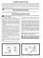
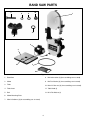
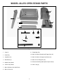
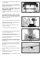
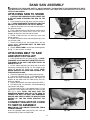
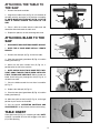
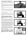
(Models 28-206, 28-276)
MODEL 28-206
SHOWN
PART NO. 906452 - 08-16-02
Copyright © 2002 Delta Machinery
To learn more about DELTA MACHINERY
visit our website at: www.deltamachinery.com.
For Parts, Service, Warranty or other Assistance,
please call
ESPAÑOL: PÁGINA 25
1-800-223-7278 (In Canada call 1-800-463-3582).
INSTRUCTION MANUAL
14" Band Saws
GENERAL SAFETY RULES
Woodworking can be dangerous if safe and proper operating procedures are not followed. As with all machinery, there
are certain hazards involved with the operation of the product. Using the machine with respect and caution will
considerably lessen the possibility of personal injury. However, if normal safety precautions are overlooked or ignored,
personal injury to the operator may result. Safety equipment such as guards, push sticks, hold-downs, featherboards,
goggles, dust masks and hearing protection can reduce your potential for injury. But even the best guard won’t make
up for poor judgment, carelessness or inattention. Always use common sense and exercise caution in the workshop.
If a procedure feels dangerous, don’t try it. Figure out an alternative procedure that feels safer. REMEMBER: Your
personal safety is your responsibility.
This machine was designed for certain applications only. Delta Machinery strongly recommends that this machine not
be modified and/or used for any application other than that for which it was designed. If you have any questions relative
to a particular application, DO NOT use the machine until you have first contacted Delta to determine if it can or should
be performed on the product.
Technical Service Manager
Delta Machinery
4825 Highway 45 North
Jackson, TN 38305
(IN CANADA: 505 SOUTHGATE DRIVE, GUELPH, ONTARIO N1H 6M7)
WARNING: FAILURE TO FOLLOW THESE RULES MAY RESULT IN SERIOUS PERSONAL INJURY
1. FOR YOUR OWN SAFETY, READ INSTRUCTION
MANUAL BEFORE OPERATING THE TOOL. Learn the
tool’s application and limitations as well as the specific
hazards peculiar to it.
2. KEEP GUARDS IN PLACE and in working order.
3. ALWAYS WEAR EYE PROTECTION. Wear safety
glasses. Everyday eyeglasses only have impact resistant
lenses; they are not safety glasses. Also use face or dust
mask if cutting operation is dusty. These safety glasses
must conform to ANSI Z87.1 requirements. NOTE:
Approved glasses have Z87 printed or stamped on them.
4. REMOVE ADJUSTING KEYS AND WRENCHES. Form
habit of checking to see that keys and adjusting wrenches
are removed from tool before turning it “on”.
5. KEEP WORK AREA CLEAN. Cluttered areas and
benches invite accidents.
6. DON’T USE IN DANGEROUS ENVIRONMENT. Don’t
use power tools in damp or wet locations, or expose them
to rain. Keep work area well-lighted.
7. KEEP CHILDREN AND VISITORS AWAY. All children
and visitors should be kept a safe distance from work area.
8. MAKE WORKSHOP CHILDPROOF – with padlocks,
master switches, or by removing starter keys.
9. DON’T FORCE TOOL. It will do the job better and be
safer at the rate for which it was designed.
10. USE RIGHT TOOL. Don’t force tool or attachment to
do a job for which it was not designed.
11. WEAR PROPER APPAREL. No loose clothing, gloves,
neckties, rings, bracelets, or other jewelry to get caught in
moving parts. Nonslip footwear is recommended. Wear
protective hair covering to contain long hair.
12. SECURE WORK. Use clamps or a vise to hold work
when practical. It’s safer than using your hand and frees
both hands to operate tool.
13. DON’T OVERREACH. Keep proper footing and
balance at all times.
14. MAINTAIN TOOLS IN TOP CONDITION. Keep tools
sharp and clean for best and safest performance. Follow
instructions for lubricating and changing accessories.
15. DISCONNECT TOOLS before servicing and when
changing accessories such as blades, bits, cutters, etc.
16. USE RECOMMENDED ACCESSORIES. The use of
accessories and attachments not recommended by Delta
may cause hazards or risk of injury to persons.
17. REDUCE THE RISK OF UNINTENTIONAL STARTING.
Make sure switch is in “OFF” position before plugging in
power cord. In the event of a power failure, move switch
to the “OFF” position.
18. NEVER STAND ON TOOL. Serious injury could occur if
the tool is tipped or if the cutting tool is accidentally
contacted.
19. CHECK DAMAGED PARTS. Before further use of the
tool, a guard or other part that is damaged should be
carefully checked to ensure that it will operate properly and
perform its intended function – check for alignment of
moving parts, binding of moving parts, breakage of parts,
mounting, and any other conditions that may affect its
operation. A guard or other part that is damaged should be
properly repaired or replaced.
20. DIRECTION OF FEED. Feed work into a blade or
cutter against the direction of rotation of the blade or cutter
only.
21. NEVER LEAVE TOOL RUNNING UNATTENDED.
TURN POWER OFF. Don’t leave tool until it comes to a
complete stop.
22. STAY ALERT, WATCH WHAT YOU ARE DOING, AND
USE COMMON SENSE WHEN OPERATING A POWER
TOOL. DO NOT USE TOOL WHILE TIRED OR UNDER
THE INFLUENCE OF DRUGS, ALCOHOL, OR
MEDICATION. A moment of inattention while operating
power tools may result in serious personal injury.
23. MAKE SURE TOOL IS DISCONNECTED FROM
P O W E R S U P P LY w h i l e m o t o r i s b e i n g m o u n t e d ,
connected or reconnected.
24. THE DUST GENERATED by certain woods and wood
products can be injurious to your health. Always operate
machinery in well ventilated areas and provide for proper
dust removal. Use wood dust collection systems whenever
possible.
25.
WARNING: SOME DUST CREATED BY
POWER SANDING, SAWING, GRINDING, DRILLING,
AND OTHER CONSTRUCTION ACTIVITIES contains
chemicals known to cause cancer, birth defects or other
reproductive harm. Some examples of these chemicals
are:
· lead from lead-based paints,
· crystalline silica from bricks and cement and other
masonry products, and
· arsenic and chromium from chemically-treated lumber.
Your risk from these exposures varies, depending on how
often you do this type of work. To reduce your exposure
to these chemicals: work in a well ventilated area, and
work with approved safety equipment, such as those
dust masks that are specially designed to filter out
microscopic particles.
SAVE THESE INSTRUCTIONS.
Refer to them often and use them to instruct others.
2
ADDITIONAL SAFETY RULES FOR
BAND SAWS
WARNING: FAILURE TO FOLLOW THESE RULES MAY RESULT IN SERIOUS PERSONAL INJURY.
1.
DO NOT OPERATE THIS MACHINE UNTIL it is
assembled and installed according to the
instructions.
15. TURN THE MACHINE “OFF” to back out of an
uncompleted or jammed cut.
2. OBTAIN ADVICE from your supervisor,
instructor, or another qualified person if you are
not familiar with the operation of this tool.
17. TURN THE MACHINE “OFF” and wait for the blade
to stop prior to cleaning the blade area, removing
debris near the blade, removing or securing
workpiece, or changing the angle of the table. A
coasting blade can be dangerous.
16. MAKE “RELIEF” CUTS prior to cutting long curves.
3. FOLLOW ALL WIRING CODES and recommended
electrical connections.
4.
USE THE GUARDS WHENEVER POSSIBLE.
Check to see that they are in place, secured, and
working correctly.
18. NEVER PERFORM LAYOUT, ASSEMBLY, or setup work on the table/work area when the machine is
running.
5.
USE PROPER BLADE SIZE and type.
6.
ADJUST THE UPPER BLADE GUIDE so that it is
about 1/8" above the workpiece.
7.
PROPERLY ADJUST the blade tension, tracking,
blade guides, and blade support bearings.
19. TURN THE MACHINE “OFF” AND DISCONNECT
THE MACHINE from the power source before
installing or removing accessories, before adjusting
or changing set-ups, or when making repairs.
8.
KEEP ARMS, HANDS, AND FINGERS away from
the blade.
9.
AVOID AWKWARD OPERATIONS and hand
positions where a sudden slip could cause a hand
to move into the blade.
20. TURN THE MACHINE “OFF”, disconnect the
machine from the power source, and clean the
table/work area before leaving the machine. LOCK
THE SWITCH IN THE “OFF” POSITION to prevent
unauthorized use.
21. ADDITIONAL INFORMATION regarding the safe
and proper operation of this tool is available from
the Power Tool Institute, 1300 Summer Avenue,
Cleveland, OH 44115-2851. Information is also
available from the National Safety Council, 1121
Spring Lake Drive, Itasca, IL 60143-3201. Please
refer to the American National Standards Institute
ANSI 01.1 Safety Requirements for Woodworking
Machines and the U.S. Department of Labor OSHA
1910.213 Regulations.
10. NEVER START THE MACHINE before clearing the
table of all objects (tools, scrap pieces, etc.).
11. NEVER START THE MACHINE with the workpiece
against the blade.
12. HOLD WORKPIECE FIRMLY against the table. DO
NOT attempt to saw a workpiece that does not have
a flat surface against the table.
13. HOLD WORKPIECE FIRMLY and feed into blade at
a moderate speed.
14. NEVER REACH UNDER THE TABLE while the
machine is running.
SAVE THESE INSTRUCTIONS.
Refer to them often
and use them to instruct others.
3
POWER CONNECTIONS
A separate electrical circuit should be used for your machines. This circuit should not be less than #12 wire and should
be protected with a 20 Amp time lag fuse. If an extension cord is used, use only 3-wire extension cords which have 3prong grounding type plugs and matching receptacle which will accept the machine’s plug. Before connecting the
motor to the power line, make sure the switch is in the “OFF” position and be sure that the electric current is of the
same characteristics as indicated on the machine. All line connections should make good contact. Running on low
voltage will damage the motor.
WARNING: DO NOT EXPOSE THE MACHINE TO RAIN OR OPERATE THE MACHINE IN DAMP LOCATIONS.
MOTOR SPECIFICATIONS
Your machine is wired for 120 volt, 60 HZ alternating current. Before connecting the machine to the power source,
make sure the switch is in the “OFF” position.
GROUNDING INSTRUCTIONS
WARNING: THIS MACHINE MUST BE GROUNDED WHILE IN USE TO PROTECT THE OPERATOR FROM
ELECTRIC SHOCK.
1. All grounded, cord-connected machines:
2. Grounded, cord-connected machines intended for use
on a supply circuit having a nominal rating less than 150
In the event of a malfunction or breakdown, grounding
volts:
provides a path of least resistance for electric current to
reduce the risk of electric shock. This machine is
If the machine is intended for use on a circuit that has an
equipped with an electric cord having an equipmentoutlet that looks like the one illustrated in Fig. A, the
grounding conductor and a grounding plug. The plug must
machine will have a grounding plug that looks like the plug
be plugged into a matching outlet that is properly installed
illustrated in Fig. A. A temporary adapter, which looks like
and grounded in accordance with all local codes and
the adapter illustrated in Fig. B, may be used to connect
ordinances.
this plug to a matching 2-conductor receptacle as shown
in Fig. B if a properly grounded outlet is not available. The
Do not modify the plug provided - if it will not fit the outlet,
temporary adapter should be used only until a properly
have the proper outlet installed by a qualified electrician.
grounded outlet can be installed by a qualified electrician.
Improper connection of the equipment-grounding
The green-colored rigid ear, lug, and the like, extending
conductor can result in risk of electric shock. The
from the adapter must be connected to a permanent
conductor with insulation having an outer surface that is
ground such as a properly grounded outlet box. Whenever
green with or without yellow stripes is the equipmentthe adapter is used, it must be held in place with a metal
grounding conductor. If repair or replacement of the
screw.
electric cord or plug is necessary, do not connect the
equipment-grounding conductor to a live terminal.
NOTE: In Canada, the use of a temporary adapter is not
permitted by the Canadian Electric Code.
Check with a qualified electrician or service personnel if
t h e g ro u n d i n g i n s t r u c t i o n s a re n o t c o m p l e t e l y
understood, or if in doubt as to whether the machine is
WARNING: IN ALL CASES, MAKE CERTAIN THE
properly grounded.
RECEPTACLE IN QUESTION IS PROPERLY
G R O U N D E D . I F Y O U A R E N O T S U R E H AV E A
Use only 3-wire extension cords that have 3-prong
QUALIFIED ELECTRICIAN CHECK THE RECEPTACLE.
grounding type plugs and matching 3-conductor
receptacles that accept the machine’s plug, as shown in
Fig. A.
Repair or replace damaged or worn cord immediately.
GROUNDED OUTLET BOX
GROUNDED OUTLET BOX
GROUNDING
MEANS
CURRENT
CARRYING
PRONGS
ADAPTER
GROUNDING BLADE
IS LONGEST OF THE 3 BLADES
Fig. A
4
Fig. B
3. Grounded, cord-connected machines intended for
use on a supply circuit having a nominal rating between
150 - 250 volts, inclusive:
GROUNDED OUTLET BOX
CURRENT
CARRYING
PRONGS
If the machine is intended for use on a circuit that has an
outlet that looks like the one illustrated in Fig. C, the
machine will have a grounding plug that looks like the
plug illustrated in Fig. C. Make sure the machine is
connected to an outlet having the same configuration as
the plug. No adapter is available or should be used with
this machine. If the machine must be re-connected for
use on a different type of electric circuit, the reconnection should be made by qualified service
personnel; and after re-connection, the machine should
comply with all local codes and ordinances.
GROUNDING BLADE
IS LONGEST OF THE 3 BLADES
Fig. C
EXTENSION CORDS
Use proper extension cords. Make sure your extension cord is in good condition and is a 3-wire extension cord which
has a 3-prong grounding type plug and matching receptacle which will accept the machine’s plug. When using an
extension cord, be sure to use one heavy enough to carry the current of the machine. An undersized cord will cause
a drop in line voltage, resulting in loss of power and overheating. Fig. D, shows the correct gauge to use depending
on the cord length. If in doubt, use the next heavier gauge. The smaller the gauge number, the heavier the cord.
MINIMUM GAUGE EXTENSION CORD
MINIMUM GAUGE EXTENSION CORD
RECOMMENDED SIZES FOR USE WITH STATIONARY ELECTRIC MACHINES
RECOMMENDED SIZES FOR USE WITH STATIONARY ELECTRIC MACHINES
Ampere
Rating
Volts
Total Length
of Cord in Feet
Gauge of
Extension Cord
Ampere
Rating
Volts
Total Length
of Cord in Feet
Gauge of
Extension Cord
0-6
0-6
0-6
0-6
120
120
120
120
up to 25
25-50
50-100
100-150
18 AWG
16 AWG
16 AWG
14 AWG
0-6
0-6
0-6
0-6
240
240
240
240
up to 50
50-100
100-200
200-300
18 AWG
16 AWG
16 AWG
14 AWG
6-10
6-10
6-10
6-10
120
120
120
120
up to 25
25-50
50-100
100-150
18 AWG
16 AWG
14 AWG
12 AWG
6-10
6-10
6-10
6-10
240
240
240
240
up to 50
50-100
100-200
200-300
18 AWG
16 AWG
14 AWG
12 AWG
10-12
10-12
10-12
10-12
120
120
120
120
up to 25
25-50
50-100
100-150
16 AWG
16 AWG
14 AWG
12 AWG
10-12
10-12
10-12
10-12
240
240
240
240
up to 50
50-100
100-200
200-300
16 AWG
16 AWG
14 AWG
12 AWG
12-16
12-16
12-16
120
120
120
up to 25
25-50
14 AWG
12 AWG
12-16
12-16
12-16
240
240
240
up to 50
50-100
14 AWG
12 AWG
GREATER THAN 50 FEET NOT RECOMMENDED
GREATER THAN 100 FEET NOT RECOMMENDED
Fig. D
Fig. D
OPERATING INSTRUCTIONS
FOREWORD
The Delta Model 28-206 is a 1 Hp, 120/240 V, 2 speed unit with a quick blade tensioning device and an enclosed stand.
The Delta Model 28-276 is a ¾ Hp, 120/240 V, 1 speed unit with a quick blade tensioning device and an open stand.
UNPACKING AND CLEANING
Carefully unpack the machine and all loose items from the shipping container(s). Remove the protective coating from
all unpainted surfaces. This coating may be removed with a soft cloth moistened with kerosene (do not use acetone,
gasoline or lacquer thinner for this purpose). After cleaning, cover the unpainted surfaces with a good quality household
floor paste wax.
NOTICE: THE MANUAL COVER PHOTO ILLUSTRATES THE CURRENT
PRODUCTION MODEL. ALL OTHER ILLUSTRATIONS ARE REPRESENTATIVE
ONLY AND MAY NOT DEPICT THE ACTUAL COLOR, LABELING OR
ACCESSORIES AND MAY BE INTENDED TO ILLUSTRATE TECHNIQUE ONLY.
5
BAND SAW PARTS
7
8
10
9
1
12
11
2
3
4
5
6
Fig. 2
1.
Band Saw
8.
M8 Lockwasher (4) (for assembling saw to stand)
2.
Motor
9.
M8 Flat Washer (4) (for assembling saw to stand)
3.
Table
10. M8x1.25 Hex nut (4) (for assembling saw to stand)
4.
Table Insert
11. Table Knob (2)
5.
Belt
12. M13 Flat Washer (2)
6.
Motor Mounting Plate
7.
M8x1.25x80mm (4) (for assembling saw to stand)
6
MODEL 28-206 ENCLOSED STAND PARTS
1
3
2
4
12
11
6
7
5
13
8
10
9
14
15
16
Fig. 3
1. Base (2)
9. M5x0.8x10mm Pan Head Screw (2)
2. Side (2)
10. Shaft (for attaching motor plate to top of stand)
3. Stand Top
11. M8x1.25 Hex nut
4. Door (2)
12. Dampening Cap
5. Pulley Guard
13. M8x1.25 Hex Flange Nut (30)
6. M8x1.25x100mm Hex Head Screw
14. 5mm Flat Washer (2)
7. M8x1.25x16mm Hex Head Flange Screw (26)
15. M5x0.8 Hex Nut (2)
8. M8x1.25x16mm Round Head Flange Screw (4)
16. 9mm C ring (2)
7
MODEL 28-276 OPEN STAND PARTS
5
1
2
6
3
4
7
9
8
10
12
11
14
13
Fig. 4
1. Legs (4)
9. Dampening Cap
2. Stand Top
10. M8x1.25x16mm Round Head Flange Screw (4)
3. Long Brace (2)
11. M8x1.25x16mm Carriage Head Screw (32)
4. Short Brace (2)
12. M8x1.25 Hex Flange Nut (38)
5. Upper Pulley Guard
13. Shaft (for attaching motor plate to top of stand)
6. Lower Pulley Guard
14. 9mm C ring (2)
7. M8x1.25x80mm Hex Head Screw
8. M8x1.25 Hex Nut
8
MODEL 28-206 ENCLOSED STAND ASSEMBLY
WARNING: FOR YOUR OWN SAFETY, DO NOT CONNECT THE MACHINE TO THE POWER SOURCE UNTIL
THE MACHINE IS COMPLETELY ASSEMBLED AND YOU READ AND UNDERSTAND THE ENTIRE
INSTRUCTION MANUAL.
1. Place the stand top (A) Fig. 5, on a flat surface as
shown.
C
E
2. Align the two holes in the motor mounting plate (E)
Fig. 5, with the two holes (B) in the stand top (A).
D
B
3. Insert shaft (D) through the holes in the motor
mounting plate and the holes in the stand top.
A
C
4. Attach the two “C” rings (C) Fig. 5 to the shaft.
Fig. 5
5. Align the four holes on the motor bracket with the
four holes (C) Fig. 6, on the motor mounting plate.
NOTE: MAKE SURE THAT THE MOTOR PULLEY (A)
FIG. 6, IS MOUNTED ON THE SIDE WITH THE BELT
OPENING HOLE (B).
A
C
6. Insert a M8x1.25x16mm round head flange screw
through the hole in the motor bracket and the hole in the
motor mounting plate.
7. Thread a M8x1.25 hex flange nut onto the screw.
B
8. Repeat this process for the three remaining holes in
the motor bracket and the motor mounting plate.
Fig. 6
9. Align the holes in the side (A) Fig. 7, with the holes
in the stand top (B).
NOTE: MAKE SURE THAT THE HINGE CATCHES (C)
FIG. 7 ARE POINTED TOWARD THE STAND TOP (B)
AS SHOWN.
10. Insert a M8x1.25x16mm hex head flange screw
through the hole in the side of stand and through the
hole in the top of stand.
A
C
11. Thread a M8x1.25 flange nut onto the screw. NOTE:
DO NOT COMPLETELY TIGHTEN THE HARDWARE
AT THIS TIME.
B
12. Repeat this process for the five remaining holes in
the side and top of stand.
Fig. 7
13. Assemble the other stand side in the same manner.
9
14. Align the holes in the base (A) Fig. 8, with the holes
in the two sides (B).
15. Insert a M8x1.25x16mm hex head flange screw
through the hole in the side of the stand (B) Fig. 8, and
through the hole in the base (A).
A
C
C
16. Thread a M8x1.25 hex flange nut onto the screw.
NOTE: DO NOT COMPLETELY TIGHTEN THE
HARDWARE AT THIS TIME.
B
17. Repeat this process for the five remaining holes in
the base.
Fig. 8
18. Assemble the other side of the base in the same
manner. Attach the two bases together by inserting a
M8x1.25x16mm hex head flange screw through the hole
(C) Fig. 8, in each base, and thread a M8x1.25 hex
flange nut onto the screw.
D
19. Turn the stand over so that it is resting on the base.
C
B
20. Slide the two hinges (A) Fig. 9 of the door over the
hinge catches (B), on the stand.
A
21. Close the door until the door latch (C) Fig. 9,
engages with the side (D).
Fig. 9
22. Attach the other door in the same manner.
23. Thread a M8x1.25 hex nut onto a M8x1.25x100mm
hex head screw approximately 1/4".
D
B
B
24. Thread the M8x1.25x100mm hex head screw (C)
into the hole (A) Fig. 10, in the top of the stand.
25. Place the damping cap (A) Fig. 10A onto the
threaded end of the screw (C).
C
A
26. Align the holes (D) Fig. 10, on the hinges that are
attached to the pulley guard, with the two holes (B) in the
top of the stand.
Fig. 10
27. Insert a M5x0.8x10mm pan head screw through the
hole (D) Fig. 10, in the hinge, and the hole (B) in the top
of the stand.
28. Place a 5mm flat washer onto the screw.
29. Thread a M5x0.8 hex nut onto the screw and tighten
securely.
C
A
30. Repeat this process for the remaining hole in the
hinge and the top of the stand.
Fig. 10A
31. Make sure the stand is level and tighten all stand
hardware at this time.
10
MODEL 28-276 OPEN STAND ASSEMBLY
WARNING: FOR YOUR OWN SAFETY, DO NOT CONNECT THE MACHINE TO THE POWER SOURCE UNTIL
THE MACHINE IS COMPLETELY ASSEMBLED AND YOU READ AND UNDERSTAND THE ENTIRE
INSTRUCTION MANUAL.
1. Place the stand top (A) Fig. 10, on a flat surface as
shown.
E
C
2. Align the two holes in the motor mounting plate (E)
Fig. 11, with the two holes (B) in the stand top (A).
B
3. Insert shaft (D) through the holes in the motor
mounting plate and the holes in the stand top.
D
A
4. Attach the two “C” rings (C) Fig. 11 to the shaft.
C
Fig. 11
5. Align the four holes on the motor bracket with the
four holes (C) Fig. 12, on the motor mounting plate.
NOTE: MAKE SURE THAT THE MOTOR PULLEY (A)
FIG. 12, IS MOUNTED ON THE SIDE WITH THE BELT
OPENING HOLE (B).
A
B
6. Insert a M8x1.25x16mm round head flange screw
through the hole in the motor bracket and the hole in the
motor mounting plate.
C
7. Thread a M8x1.25 hex flange nut onto the screw.
8. Repeat this process for the three remaining holes in
the motor bracket and the motor mounting plate.
Fig. 12
9. Align the four holes (A) Fig. 13 in the leg with the four
holes in the side of the stand top (B).
B
10. Insert a M8x1.25x16mm hex head flange screw
through the hole in the leg and through the hole in the
top of stand.
A
11. Thread a M8x1.25 flange nut onto the screw. NOTE:
DO NOT COMPLETELY TIGHTEN THE HARDWARE
AT THIS TIME.
12. Repeat this process for the three remaining holes in
the leg.
Fig. 13
13. Attach the three remaining stand legs in the same
manner.
11
A
14. Align the four holes in the short brace (A) Fig. 14,
with the four holes in the two legs (B).
15. Insert a M8x1.25x16mm carriage head bolt through
the hole in the stand and the hole the short brace.
A
16. Thread a M8x1.25 flange nut onto the screw. NOTE:
DO NOT COMPLETELY TIGHTEN STAND HARDWARE
AT THIS TIME.
B
17. Repeat this process for the three remaining holes in
the short brace.
Fig. 14
18. Attach the remaining short brace to the opposite
side of the stand in the same manner.
B
A
19. Align the four holes in the long brace (A) Fig. 15, with
the four holes in the two legs (B).
20. Insert a M8x1.25x16mm carriage head bolt through
the hole in the stand and the hole in the long brace.
21. Thread a M8x1.25 flange nut onto the screw. NOTE:
DO NOT COMPLETELY TIGHTEN STAND HARDWARE
AT THIS TIME.
Fig. 15
22. Repeat this process for the three remaining holes in
the long brace.
23. Attach the remaining long brace to the opposite side
of the stand in the same manner.
D
A
24. Turn the stand over so that it is resting on its legs.
B
25. Thread a M8x1.25 hex nut onto a M8x1.25x80mm
hex head screw approximately 1/4".
26. Thread the M8x1.25x80mm hex head screw into the
hole (A) Fig. 16, in the top of the stand.
27. Place the damping cap (A) Fig. 16A onto the
threaded end of the screw (C).
C
Fig. 16
28. Insert the two threaded studs on the lower pulley
guard (C) Fig 16, through the two holes in the top of the
stand (B).
29. Align the two holes in the upper pulley guard (D) Fig.
16, with the two threaded studs on the lower pulley
guard (C). Place the upper pulley guard on the studs of
the lower pulley guard.
C
30. Thread an M8x1.25 hex flange nut onto each of the
studs and tighten securely.
A
31. Make sure the stand is level and tighten all stand
hardware at this time.
Fig. 16A
12
BAND SAW ASSEMBLY
WARNING: FOR YOUR OWN SAFETY, DO NOT CONNECT THE MACHINE TO THE POWER SOURCE UNTIL
THE MACHINE IS COMPLETELY ASSEMBLED AND YOU READ AND UNDERSTAND THE ENTIRE
INSTRUCTION MANUAL.
ATTACHING SAW TO STAND
1. CAUTION: THE BAND SAW IS VERY HEAVY. USE
A HELPER WHEN ATTACHING THE SAW TO THE
STAND.
2. Place the band saw on top of the stand as shown in
Fig. 17. NOTE: MAKE SURE THE PULLEY IS ON THE
SIDE OF THE STAND WITH THE PULLEY GUARD.
3. Align the four holes in the saw with the four holes in
the top of the stand.
4. Place a M8 lockwasher and a M8 flat washer onto a
M8x1.25x80mm hex head screw. Insert the screw
through the hole (A) in the saw and the stand.
5. Thread a M8x1.25 hex nut onto the screw and
tighten securely.
6. Repeat this process for the remaining hole (A) in the
saw and the stand.
7. Attach the belt to saw and motor pulley, see the
section below “ATTACHING BELT TO SAW AND
MOTOR PULLEY”.
8. Repeat STEPS 4 AND 5, for the two remaining holes
(B) Fig. 17, (one of which is shown).
B
A
A
Fig. 17
ATTACHING BELT TO SAW
AND MOTOR PULLEY
1. Place the belt over the saw pulley (A) Fig. 18. NOTE:
THE MODEL 28-276 HAS ONLY A ONE STEP PULLEY.
THE MODEL 28-206 HAS A TWO STEP PULLEY AS
SHOWN IN FIG. 18.
2. Lift the motor and place the other end of the belt
around the motor pulley (B) Fig. 18. The weight of the
motor will provide the correct belt tension. NOTE:
NEVER OPERATE THE BAND SAW WITHOUT ALL
THE GUARDS IN PLACE.
3. Check the alignment of the motor and saw pulley.
4. Loosen the four bolts (C) Fig. 12, that hold the motor
bracket to the motor mounting plate, and adjust the
position of the motor until the motor pulley and saw
pulley are aligned.
5. Tighten the four bolts that were loosened in STEP 4.
6. Turn bolt (C) Fig. 18, clockwise, until the dampening
cap contacts the motor.
7. Back the bolt (C) Fig. 18, out approximately 1/4" and
tighten the nut (D) against the top of the stand to hold
bolt (C) in place. NOTE: THE BOLT AND THE
DAMPENING WASHER ARE NOT TO BE USED TO
TENSION THE BELT. THE BOLT AND DAMPENING
WASHER ARE USED TO KEEP THE MOTOR FROM
RAISING UP TOO FAR WHEN STARTING THE
MOTOR.
C
D
A
B
Fig. 18
CONNECTING MOTOR CORD
TO SWITCH ASSEMBLY
B
WA R N I N G : DISCONNECT MACHINE FROM
POWER SOURCE.
Insert the pronged motor plug (A) Fig. 18A, into the
receptacle (B) of switch-to-motor cord.
Fig. 18A
13
A
ATTACHING THE TABLE TO
THE SAW
C
1. Remove the band saw blade.
A
A
2. Align the two table studs (A) Fig. 19, in the bottom of
the table, with the two holes in the trunnion assemblies
(B). NOTE: MAKE SURE THE SLOT (C) FIG. 19, IN THE
TABLE IS FACING TOWARD THE FRONT OF THE
SAW.
B
B
3. Place a M13 flat washer onto the table stud and
thread the table knob onto the table stud.
Fig. 19
4. Repeat this process for the remaining table stud.
ATTACHING BLADE TO THE
SAW
B
D
1. DISCONNECT MACHINE FROM POWER SOURCE.
E
2. NOTE: THE 14" BAND SAWS USE 93½" LENGTH
BLADES.
A
B
3. Remove the table pin (A) Fig. 20 from the table.
C
4. Open the two wheel guard doors (B) Fig. 20, and the
blade guard door (C).
Fig. 20
5. Make sure the quick tension lever (D) Fig. 20, is
positioned to the left of the machine.
6. NOTE: CHECK BLADE TO BE SURE TEETH WILL
POINT DOWN TOWARD TABLE WHEN INSTALLED.
IF NOT, TURN BLADE INSIDE OUT. Slide the band saw
blade, (teeth facing out), through the slot (E) Fig. 20, in
the band saw table.
A
7. Place the blade around the two wheel assemblies
(A) Fig. 21.
8. Replace the table pin (A) Fig. 20.
Fig. 21
9. Close the two wheel guard doors (B) Fig. 20, and the
blade guard door (C).
10. Move the quick tension lever (D) Fig. 20, to the right
position to put tension on the blade.
11. See the section “OPERATING CONTROLS AND
ADJUSTMENTS” to adjust blade tension and tracking.
C
TABLE INSERT
B
Place table insert (A) Fig. 22, in opening of table. NOTE:
A tab (B) is provided on insert that engages with notch
(C) in table opening.
A
Fig. 22
14
OPERATING CONTROLS AND ADJUSTMENTS
STARTING AND
STOPPING SAW
The power switch is located on the left side of the
machine. To turn the machine “ON”, push the green
start button (A) Fig. 23. To turn the machine “OFF”, push
the red stop button (B).
A
B
Fig. 23
LOCKING SWITCH IN THE
“OFF” POSITION
IMPORTANT: When the tool is not in use, the switch
should be locked in the “OFF” position to prevent
unauthorized use, using a padlock (C) Fig. 24 with a
3/16" diameter shackle.
C
Fig. 24
TILTING THE TABLE
1. The table on the band saw can be tilted 45 degrees
to the right and 10 degrees to the left. To tilt the table to
the right, loosen the two locking knobs (A) Fig. 25, tilt the
table to the desired angle as shown on the scale (D)
Figs. 25 and 26, and tighten two locking knobs (A).
D
A
A
Fig. 25
2. To tilt the table (C) Fig. 26 to the left, loosen the two
locking knobs (A) Fig. 25, and tilt the table to the right
until access to the table stop (A) Fig. 26 is gained.
Remove the table stop (A) Fig. 26, and tilt the table to the
left 10 degrees. Tighten the two locking knobs (A) Fig.
25.
E
C
D
A
B
Fig. 26
15
F
ADJUSTING THE TABLE STOP
The tool is equipped with an adjustable table stop (A)
Fig. 26 that allows the table to be set at 90 degrees to
the blade.
Tilt the table (C) Fig. 26 to the left until the table stop (A)
Fig. 26 contacts the table. Place a square on the table
against the blade (Fig. 27). Check to see if the blade is
90 degrees to the table surface. If not, then do the
following:
1. Tilt the table slightly to the right and tighten the table
lock knobs.
Fig. 27
2. Loosen the locknut (B) Fig. 26 to free the adjusting
screw (A) Fig. 26. Turn the adjusting screw (A) right or left
to raise or lower the table stop, then tighten the locknut
(B).
3. Lower the table. Check to see that the table is 90
degrees to the blade (Fig. 27).
4. When the table is 90 degrees to the blade, check the
pointer (E) Fig. 26 to see if it points to 0°. If not, loosen
the screw (F) Fig. 26 and move the pointer to 0°. Tighten
the screw.
A
ADJUSTING BLADE TENSION
CAUTION: DISCONNECT MACHINE FROM POWER
SOURCE.
Fig. 28
The Band Saw is equipped with a tension handle (A) Fig.
28. To apply tension, move the tension handle (A) Fig. 28
to the right as shown. To release the blade tension,
move the tension handle (A) Fig. 29, to the left as shown.
To adjust the blade tension, the blade tension handle
must be in the right as shown in Fig. 28. A series of
graduations is located on the back of the upper wheel
slide bracket. These graduations indicate the proper
tension for various widths of blades. With the blade on
the wheels, turn the knob (A) Fig. 30 to raise or lower the
wheel, until the red fiber washer (B) Fig. 30 is in line with
the proper graduation for the size of the blade used.
A
Fig. 29
These graduations are correct for average work, and will
not be affected by rebrazing of the saw blade. Use these
graduations until you become familiar enough with the
operation of the band saw to vary the tension for
different kinds of blades or work.
A
B
IMPORTANT: OVER-STRAINING IS A COMMON
CAUSE OF BLADE BREAKAGE AND OTHER
UNSATISFACTORY
BLADE
PERFORMANCE.
RELEASE THE TENSION WHEN THE TOOL IS NOT IN
USE.
Fig. 30
16
TRACKING THE BLADE
A
CAUTION: DISCONNECT MACHINE FROM POWER
SOURCE.
IMPORTANT: Before tracking the blade, make sure that
the blade guides and blade support bearings are clear of
the blade.
After applying tension to the blade, rotate the wheels
slowly forward by hand and observe the blade’s
movement. The blade (A) Fig. 31 should travel in the
center of the upper tire. If the blade creeps toward the
front edge, loosen the wing nut (B) Fig. 32, and turn the
thumb screw (C) clockwise. This action draws the blade
toward the center of the tire. If the blade creeps toward
the back edge, turn the thumb screw in the opposite
direction. Adjust the thumb screw (C) Fig. 32 only a
fraction of a turn each time. NEVER TRACK THE
BLADE WHILE THE TOOL IS RUNNING. After the
blade is tracking in the center of the tires, tighten the
wing nut (B) Fig. 32.
Fig. 31
B
C
VERTICAL ADJUSTMENT OF
THE UPPER BLADE GUIDE
ASSEMBLY
Fig. 32
CAUTION: DISCONNECT MACHINE FROM POWER
SOURCE.
Adjust the blade guides and bearings according to the
following instructions.
Set the upper blade guide assembly (A) Fig. 33 as close
as possible to the top surface of the workpiece. Loosen
the lock knob (B) and move the guide assembly (A) to
the desired position.
B
A
Fig. 33
ADJUSTING THE UPPER BLADE GUIDES
AND BLADE SUPPORT BEARING
Adjust the upper blade guides and blade support bearings ONLY AFTER the blade has the correct tension and is
tracking properly. To adjust, do the following:
1. DISCONNECT MACHINE FROM POWER SOURCE
2. Make sure that the bottom blade guides and support bearings are not touching the blade.
3. Check the upper blade guide assembly. The blade guides (A) Fig. 34 should be parallel to the blade. To adjust,
loosen the screw (B) and rotate the complete guide assembly (C). When the blade guides are parallel with the blade,
tighten the screw (B).
4. Adjust the guides (A) Fig. 35 so that the front edge of the guides are just behind the “gullets” of the saw teeth. The
complete guide block bracket can be moved in or out by loosening the thumb screw (C) and turning the knurled knob
(D) Fig. 35. When the guides (A) are set properly, tighten thumb screw (C).
17
5. Two set screws (B) Fig. 35 hold the upper blade
guides (A) in place. Loosen the set screws (B) to move
the guides (A). Place them as close as possible to the
side of the blade. (Be careful not to pinch the blade).
Tighten the screws (B).
B
C
6. The upper blade support bearing (E) Fig. 35 prevents
damage to the set in the saw teeth by keeping the blade
from being pushed too far toward the back. The support
bearing (E) should be set 1/64" behind the blade by
loosening the thumb screw (F) and turning the knurled
knob (G) to move the support bearing (E) in or out.
A
Fig. 34
7. Adjust the blade support bearing (E) so that the back
edge of the blade overlaps the outside diameter of the
ball bearing by about 1/16". The bearing (E) is set on an
eccentric. To change the position, remove the screw (H)
and bearing (E) Fig. 35. Loosen the thumb screw (F),
back out the knurled knob from the set screw. Remove
the hex shaft from the hole, and rotate it to move the
eccentric for the bearing.
F
G
H
E
8. When the blade guide wears to a point that it cannot
be adjusted close to the blade, loosen screw (B) Fig. 35
and reverse the blade guides (A) Fig. 35.
C
D
B
A
B
ADJUSTING LOWER BLADE
GUIDES AND BLADE SUPPORT
BEARING
A
Fig. 35
Adjust the lower blade guides and blade support bearing
after the the upper guides and bearing have been
adjusted.
B
E
1. DISCONNECT MACHINE FROM POWER SOURCE.
A
A
B
2. Adjust the front edge of the guide blocks (B) Fig. 36
so that they are just behind the “gullets” of the saw
teeth. Turn the knurled knob (C) Fig. 36 to make this
adjustment. Check the support bearing (D) Fig. 36. It
should not be touching the back of the blade.
C
D
3. Loosen the two screws (A) Fig. 36. Move the guides
(B) as close as possible to the side of the blade, being
careful not to pinch the blade. Tighten screws (A).
Fig. 36
4. Turn the other knurled knob (E) to adjust the lower
blade support bearing (D) Fig. 36 so that it is about 1/64"
behind the back of the blade.
DUST PORT
A dust port (A) Fig. 36A, enables you to connect your
band saw to a dust collector. The dust port is 4" O.D.
A
Fig. 36A
18
CHANGING BLADE SPEED
FOR MODEL 28-206 ONLY
1. DISCONNECT MACHINE FROM POWER SOURCE.
2. Open the pulley guard (A) Fig. 37, by removing screw
(B) and opening the pulley guard door.
B
3. Lift and hold the motor up, place the belt on desired
step of the pulleys, and release the motor.
4. The two motor speeds are 3300 fpm (feet per minute),
and 2500 fpm.
A
Fig. 37
3300 fpm is the combination of the large motor pulley
(3.15" dia) and the small saw pulley. This speed is for
general work.
2500 fpm is the combination of the small motor pulley
(2.65" dia) and the large saw pulley. This speed is for resaw
work.
A
Fig. 38
OPERATIONS
Before starting the machine, insure that all adjustments are properly made and the guards are in place. Turn the upper
wheel by hand to make sure that everything is correct BEFORE turning on the power.
Keep the top guide within 1/8" of the work piece at all times. Do not force the material against the blade. Light pressure
on the work piece will produce a smoother cut, and prevent excess friction, and heating of the blade.
KEEP THE SAW BLADE SHARP. Very little forward pressure is required for normal cutting. Keep the workpiece
moving at a slow and consistent rate against the blade to ensure a smooth and accurate cut.
Avoid twisting the blade, by trying not to turn sharp corners. Remember, you must saw around corners.
CUTTING CURVES
When cutting curves, turn the stock carefully so that the blade follows without twisting. If a curve is so abrupt that it is
necessary to repeatedly back up and cut a new kerf, a narrower blade, a blade with more set, or additional relief cuts
Fig. 39, may be necessary to allow the blade to cut more efficiently. The more set a blade has, the easier it will allow
the stock to be turned, but the cut is usually rougher.
When withdrawing the piece being cut, changing the cut, or for any other reason, be careful not to accidentally draw
the blade off the wheels. In most cases, it is easier and safer to turn the stock and saw out through the waste material,
rather than try to withdraw the stock from the blade.
Fig. 39
19
TROUBLESHOOTING GUIDE
In spite of how well a band saw is maintained, problems can occur. The following troubleshooting
guide will help you solve the more common problems:
Trouble: SAW WILL NOT START.
Probable Cause
Remedy
1. Saw not plugged in.
1. Plug in saw.
2. Fuse blown or circuit breaker tripped.
2. Replace fuse or reset circuit breaker.
3. Cord damaged.
3. Have cord replaced.
Trouble: BREAKER KICKS OUT FREQUENTLY.
Probable Cause
Remedy
1. Extension cord too light or too long.
1. Replace with adequate size cord.
2. Feeding stock too fast.
2. Feed stock more slowly.
3. Blade in poor condition (dull, warped, gummed).
3. Clean or replace blade.
4. Low voltage supply.
4. Contact an electrician.
Trouble: BAND SAW VIBRATES EXCESSIVELY.
Probable Cause
Remedy
1. Machine not mounted securely to stand.
1. Tighten all mounting hardware.
2. Stand on uneven surface.
2. Reposition on flat level surface.
3. Worn belt.
3. Replace belt.
4. Pulley not aligned.
4. Adjust pulleys.
5. Motor not fastened securely.
5. Tighten all mounting hardware.
Trouble: BAND SAW DOES NOT COME UP TO SPEED.
Probable Cause
Remedy
1. Low voltage due to improper extension cord size.
1. Replace with adequate size cord.
2. Low voltage.
2. Contact an electrician.
Trouble: BLADES BREAK.
Probable Cause
Remedy
1. Blade not tensioned properly.
1. Adjust blade tension.
2. Blade guides improperly adjusted.
2. Check and adjust blade guides.
3. Blade support bearing improperly adjusted.
3. Adjust blade support bearing.
4. Blade wheel tracking adjustment improperly set.
4. Check and adjust blade tracking.
5. Bad weld on blade.
5. Replace the blade.
6. Worn tires.
6. Replace tires.
7. Forcing wide blade around short radius.
7. Change to a narrower blade.
8. Dull blade or insufficient set.
8. Replace blade.
9. Upper blade guide set too high.
9. Set upper blade guide within 1/8" of workpiece.
10. Continuous running of machine when not actually
cutting.
10. Turn off machine when not performing cutting
operation.
(continued on next page)
20
Trouble: BLADE WILL NOT TRACK.
Probable Cause
Remedy
1. Blade too loose
1. Adjust tension
2. Upper wheel not properly adjusted.
2. Adjust upper wheel.
3. Improperly adjusted blade support bearing.
3. Adjust blade support bearing.
Trouble: CUT DOES NOT AGREE WITH SETTING ON THE TILT SCALE.
Probable Cause
Remedy
1. Pointer out of adjustment
1. Adjust pointer.
Trouble: BLADE WILL NOT STAY ON WHEEL.
Probable Cause
Remedy
1. Blade not tensioned properly.
1. Adjust blade tension.
2. Blade guides improperly adjusted.
2. Check and adjust blade guides.
3. Blade support bearing improperly adjusted.
3. Adjust blade support bearing.
4. Blade wheel not tracking properly.
4. Check and adjust blade tracking.
5. Bad weld on blade.
5. Replace the blade.
6. Worn tires.
6. Replace tires.
Trouble: BAND SAW MAKES UNSATISFACTORY CUTS.
Probable Cause
Remedy
1. Blade not tensioned properly.
1. Adjust blade tension.
2. Blade guides improperly adjusted.
2. Check and adjust blade guides.
3. Blade support bearing improperly set.
3. Adjust blade support bearing.
4. Blade wheel not tracking properly.
4. Check and adjust blade tracking.
5. Bad weld on blade.
5. Replace the blade.
6. Worn tires.
6. Replace tires.
7. Incorrect blade for work being done.
7. Change the blade.
8. Dull blade or insufficient set.
8. Replace blade.
9. Upper blade guide set too high.
9. Set upper blade guide within 1/8" of work piece.
21
BAND SAW BLADES
A band saw blade is a delicate piece of steel that is subjected to tremendous strain. You can
obtain long use from a band saw blade if you use it properly. Be sure you use blades of the proper
thickness, width and temper for the various types of material and cuts.
Always use the widest blade possible. Use narrow blades only for sawing small, abrupt curves
and for fine, delicate work. This will save blades and will produce better cuts. For cutting wood
and similar materials, Delta offers blades in widths of 1/8", 1/4", 3/8", and 1/2".
Any one of a number of conditions may cause a band saw blade to break. Blade breakage is, in
some cases, unavoidable, being the natural result of the peculiar stresses to which blades are
subjected. Blades will break often due to avoidable causes, such as the lack of care to the blade
or the blade not being properly adjusted to the band saw. The most common causes of blade
breakage are:
(1) faulty alignments and adjustments of the guides.
(2) forcing or twisting a wide blade around a curve of short radius.
(3) feeding the work piece too fast into the blade.
(4) dullness of the teeth, or absence of sufficient set.
(5) improperly tensioned blade.
(6) top guide set too high above the work piece being cut.
(7) using a blade with a lumpy or improperly finished braze or weld.
(8) continuous running of the saw blade when not cutting.
Use blades that are 93½" in length on this machine.
Always use a sharp blade. Keep it free from gum and pitch. Clean frequently with a stiff fiber
brush.
Narrow blades are used for cutting small circles or curves while the wider blades are best suited
for straight cutting such as ripping.
A new blade, in most cases, will perform better and last longer than a re-sharpened blade.
Insure that the blade guides are adjusted properly.
Do not force or twist the blade around a curve or a very short radius.
Feed the workpiece through the blade at a consistent rate, allow the blade to do the cutting – do
not feed the work piece too fast.
Do not apply excessive tension to the blade. The tension is only necessary to drive the blade
without slipping on the wheels. Narrow blades require less tension than wider blades.
22
NOTES
23
ACCESSORIES
A complete line of accessories is available from your Delta Supplier, Porter-Cable • Delta Factory Service Centers,
and Delta Authorized Service Stations. Please visit our Web Site www.deltamachinery.com for a catalog or
for the name of your nearest supplier.
WARNING: Since accessories other than those offered by Delta have not been tested
with this product, use of such accessories could be hazardous. For safest operation, only
Delta recommended accessories should be used with this product.
PARTS, SERVICE OR WARRANTY ASSISTANCE
All Delta Machines and accessories are manufactured to high quality standards and are serviced by a network
of Porter-Cable • Delta Factory Service Centers and Delta Authorized Service Stations. To obtain additional
information regarding your Delta quality product or to obtain parts, service, warranty assistance, or the location
of the nearest service outlet, please call 1-800-223-7278 (In Canada call 1-800-463-3582).
Two Year Limited Warranty
Delta will repair or replace, at its expense and at its option, any Delta machine, machine part, or machine accessory which
in normal use has proven to be defective in workmanship or material, provided that the customer returns the product
prepaid to a Delta factory service center or authorized service station with proof of purchase of the product within two
years and provides Delta with reasonable opportunity to verify the alleged defect by inspection. Delta may require that
electric motors be returned prepaid to a motor manufacturer’s authorized station for inspection and repair or replacement.
Delta will not be responsible for any asserted defect which has resulted from normal wear, misuse, abuse or repair or
alteration made or specifically authorized by anyone other than an authorized Delta service facility or representative. Under
no circumstances will Delta be liable for incidental or consequential damages resulting from defective products. This
warranty is Delta’s sole warranty and sets forth the customer’s exclusive remedy, with respect to defective products; all
other warranties, express or implied, whether of merchantability, fitness for purpose, or otherwise, are expressly
disclaimed by Delta.
Printed in U.S.A.
24