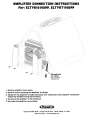
1
LA I
T
Dear customer,
Congratulations on your purchase of a Bazooka high-performance amplifier. Rt Bazooka,
we are fanatics about accurate music reproduction. Your selection of our products for
your sound system indicates that quality sound is also important to you too. Rt SRS, we
take great pride in manufacturing revolutionary audio products, and through the years of
engineering expertise, hand craftsmanship and critical testing procedures, we have
created this high-performance series of amplifiers. We hope that you will take as much
pride in owning and using one of these high-quality audio products as we do designing and
manufacturing them.
When properly installed and operated, your Bazooka ELR amplifier will give you years of
clean uninterrupted sound reproduction. Therefore, we urge you to take a few minutes to
carefully read through this manual. It will explain all of the features of your amplifier and
help insure trouble free installation.
Sound can be deceiving. Over time your hearing comfort level adapts to higher volumes of
sound. What may have sounded normal can actually be too loud and harmful to your hearing.
Guard against this by setting your equipment at a safe level before your hearing adapts.
To establish a "safe leveP',
Start with your volume control at a low setting.
Slowly increase the volume control until you can hear comfortably, clearly and
without distortion.
Once you have established a comfortable "sound level'" make a note of this
position and do not go above this setting
Taking a minute to do this will help prevent your hearing from being damaged and allow you
to enjoy listening to music throughout your lifetime.
2
ELR RMPLIFIERS
SRFETY PRECRUTIONS
Fuse amplifierspower wire at the battery.
Be sure to fuse the power wire within 12" of the car's battery. This will protect the car's
battery in case of a short circuit between the power amplifier and battery. THIS IS AMUST,
the amplifier's built-in fuse will only protect the power amplifier not the car's battery!
Use high grade wire connectors.
To ensure maximum power transfer and secu~ safe connections, it is recommended to
use high grade barrier spades (for connection at amplifier if applicable) and terminal rings
(for connection at battery).
Do notrun any wires underneath vehicle.
Exposed wires have a chance of being cut or damaged. It is best to run all wires through
the vehicle under the carpet and/or side panels. This lends to a cleaner installation and
less risk of damage.
Use caution when mounting amplifier.
Remember there are many electrical wires, gas lines, vacuum lines, brake lines as well as a
gas tank in the automobile. Make sure you know where they are when mounting the
amplifier to avoid puncturing lines, shorting wires or drilling holes in the gas tank.
Run signal wires awayfrom electrical wires.
To avoid possibility of induced noise from the car's electrical system (i.e. popping noises or
engine noise), run wires away from the carls electrical wiring.
Make allground wires as short aspossible andat the samepoint
In order to reduce the chance of ground loops (i.e. engine noise), make the grounding wire
as short as possible to reduce the wire's resistance. Also, when using multiple
components, make sure all units are grounded at the same point.
Rvoidsharp edges when running the wires.
To avoid the possibility of power, signal or speaker shorts, be careful not to allow the
amplifiers wires to come in contact with sharp edges. Use a grommet to protect the wire
when running through the fire wall.
3
FERTURES RND BENEFITS
DC OffsetProtection
This circuit protects the output of the amplifier against DC voltage. If for some reason DC
voltage is detected at the output stage, the amplifier will shut down protecting the
speakers from direct current.
ShortCircuit Protection
The circuit protects the amplifier from damage due to a short found in the speakers or
wiring. If one of the speakers or its wiring comes in contact with ground, the amplifier will
shut down. To resume normal operation, correct the problem and turn the head unit off.
then back on. The amplifier will reset and play again.
Thermal Protection
To protect the amplifier circuitry against damage caused by prolonged exposure to high
temperatures, a thermal protection circuit is activated if the amplifier reaches
excessively high operating temperature. Once the thermal circuit is activated, the
amplifier will shut down to cool off. The amplifier will automatically turn back on once it
cools down to a safe operating temperature.
Tri Mode Capable (El.R265, ELR2100, &ELR2150)
If so desired, the amplifier may be run in stereo and mono at the same time. For example,
this feature would allow you to run a pair of mid and tweeters in stereo and a sub-woofer
mono (See Page 13).
Built-in Crossover
The "ELFI"amplifiers include a built-in variable """high and low pass crossovers. The
crossover features a variable frequency selection (50Hz"" 250Hz) for precise high or low
pass filtering. **Except ELFl1190, 1300, 1500 & 1800 which have a 50 "" 250Hz low pass filter.
Bass Boost
For added low frequency performance the amplifiers are equipped with switchable 6 or
12dB bass boost @ 45Hz.
Line out
One set of full range line outputs have been provided for convenient connection to
additional amplifiers in the system. (Fill models except ELFl465 &ELFl2150)
4
ELR RMPLIFIERS
Subsonic Filter (ELR1190, ELR1300, ELR1500 & ELR1BOO)
R subsonic filter has been provided to filter out unwanted subsonic bass frequencies
below the audible range of the subwoofer. This feature helps to improve the amplifier IS
overall performance since power is not wasted reproducing frequencies beyond the
speakers ' normal operating range. This feature works in conjunction with the Low-pass
crossover to provide band-pass filtering.
Phase Rdjustment (ELR1190, ELR1300, ELR1500 & ELR1BOO)
The phase switch allows for 0 or 180 degree phase adjustment for the woofers. In most
systems, this phase adjustment should be set at 0 degrees. The 180-degree setting is only
needed if the subwoofers are out of phase with the satellite speakers in the vehicle.
Power Fusing
This protects the amplifier against short circuits and excessive current.
Remote Turn-on
Rutomatically turns amplifier on when connected to the head unit's remote output. The
amplifier will turn on and off with the head unit to save current consumption. This control
also operates the reset circuit for the amplifier's protection. It must be connected with
the head unit in order to reset protection circuits.
Rdjustable Input Sensitivity
Rllows you to fine-tune the level matching between your source and the power amplifier.
5
MOUNTING LoeRTION
8E!forE! you start thE! installation. it will bE! nE!cE!ssary to find a mounting location for thE!
amplifiE!r. Find a location in which thE! amplifiE!r will rE!cE!ivE! adE!QuatE! vE!ntiiation in ordE!r
to dissipatE! thE! hE!at it dE!vE!lops during opE!ration. Two popular mounting locations arE! in
thE! trunk or undE!r thE! sE!at.
SE!IE!ct thE! location in which you wish to mount thE! amplifiE!r. USE! caution whE!n mounting
amplifiE!r. thE!rE! arE! many wirE!s. gas linE!s. vacuum linE!s. brakE! linE!s as WE!II as a gas tank in
thE! automobilE!. MakE! surE! you know whE!rE! thE!Y arE! whE!n mounting thE! amplifiE!r to avoid
puncturing linE!s, shorting wirE!s or drilling holE!S in thE! gas tank. OnCE! you arE! rE!ady. USE! a
pE!ncil to mark thE! mounting holE!S in thE! bottom panE!1. RftE!r you havE! markE!d thE! locations
of thE! holE!s mOVE! amplifiE!r out of thE! way and drill small startE!r holE!s to makE! thE! tapping
scrE!WS E!asiE!r to install. Use providE!d screws to tighten down thE! amplifie 1'.
T
T
T
T
I
I
I
I
I
I
I
I
I
I
I
I
I
I
I
•
I
I
•
I
I
I
I
•
I
I
6
ELR RMPLIFIERS
POWER CONNECTIONS
IN-LINE POWER FUSE
MOUNTED WITHIN 12'
FROM BATIERY RECOMMENDED
(NOT PROVIDED)
~
RADIO'S REMOTE
TURN-QN OUTPUT
~~~~
I
94. 7 I c::::::::J c::::::J
()
I
I
I
I
'"
I
I
IMPORTRNT! Before making any connections, disconnect the car's battery until the
installation is completed to avoid possible damage to the electrical system.
Connect the amplifier to the car's battery.
At times. the amplifier will need to draw large levels of current that cannot be provided by
any circuit in the carls fuse box. We recommended using an 4 to 8 gauge power wire for
your connections depending on the amplifier and length of the wire. Strip one end of the
wire to crimp on a barrier spade. Loosen the +12V screw terminal and insert the power
wire with the barrier spade and tighten. Use caution to make sure no stray wire stands
come in contact with surrounding terminals causing short circuits. Run the wire directly
to the positive terminal of the car's battery. Make sure to use an in-line fuse within 12" of
the car's battery to protect the electrical system and amplifier against short circuits
and/or power surges.
Connect the ground terminal of the amplifier to the carls chassis.
For the ground connection. use an 4 to 8 gauge wire (black) to connect to the terminal
marked GNO and then connect it to the car's chassis. Try to keep the length of the cable as
short as possible. preferably less than 6". Also make sure that the point on the car where
the connection is to be made is free of paint and dirt.
Connect the remote terminal of the amplifier to a switchable +12V source.
This connection allows the amplifier to be turned on and off with the power control of the
radio. If the radio has a REMOTE output terminal, connect it to the amplifier's terminal
marked REMOTE (using a 16 gauge wire or heavier). Now when the radio is turned on, the
amplifier will automatically turn on. This connection can also be made to the radio's Power
Antenna wire.
7
SIGNRL CONNECTIONS
Connect the HCR output of the head unit (RM/FM cassette player, CD, or DRT) to the HCR
input terminals of the amplifier.
To make these connections, we recommend high quality RCR cables. which arl:! available at
your local car audio retailer. Run signal wires away from electrical wires to avoid
possibility of induced noise from the car's electrical system (i.e. popping noises or engine
noise). Please note that when making these connections the signal inputs correspond with
the speaker outputs.
SUBSONIC
OREJoN
o
MIN
MAl(
GAIN
Optional full range line out
connection to additional amplifiers
rc~~~~~~~~~~l
in the system.
o
o
_-=--94=.7--,) c==J c==J
L-I
L-[
11I111111
_-=--94=,7--.J) c:=:=:J E==::J
1111I1111
ELR265, ELR1190. ELA2100 &. ELA2150
SIGNAL CONNECTIONS
ELR1300. ELR1500, &. ELR1800
SIGNAL CONNECTIONS
oI
94.7
ill
I c:==:::J c:==:::J
J
FRONT
I!
II
REAR
ELR465 SIGNAL CONNECTIONS
8
ELR RMPLIFIERS
HIGH LEVEL CONNECTIONS (OPTIONRL)
High Level inputs have been included to connect the amplifier to a radio without low-level
outputs (i.e. factory radio). This connection will allow you to connect directly to the
speaker output of the radio with out the need of an external adapter.
Determine the type of radio you have and make one of the following connections.
CRUTION!
damag~
to
B~for~ making any conn~ctions d~t~rmin~ th~ typ~ of radio to avoid possibl~
and/or radio.
amplifi~r
LINE IN
SUBSONac
LINE OUT
~
JOaN
.~AA
C®@~
H'GH.'NP,UT
GNO-'t-+
GAIN
I
•
•
1....._..;.,.94~,7-J1
MIN
MAX
j£]
~~BSO:C
I
~
®
GAIN
0
.....
, _..;.,.94:.;..:.,7-J) c:::::J r::::::J
o
hJfi"'! E:::J
III1IIIII
IIIIIIIII
BLACK
(NOT USED)
GRAYIBLACK
RIGHT -
GRAY
RIGHT +
GRAY
RIGHT +
GREENIBLACK
LEFT-
GRAYIBLACK
RIGHT -
GREEN
LEFT +
BLACK
(NOT USED)
GREEN
LEFT +
GREENIBLACK LEFT-
EU11190. ELA1500 & ELA1BOO
ELA265. ELA2100. ELA1190 & ELA2150
TWO CHANNEL CONNECTIONS: FLOATING GROUND RADIO (MOST COMMON TYPE)
SUBSONIC
JIO
:~
GAIN
o
IIIIIII
I
GRAY
I
I
I
I
I
LEFT +
....._ -. . . GREENIBLACK NOT USED
NOT USED
RIGHT+
GRAY
.....- - -. . . GRAYIBLACK
....- - - _ GREENIBLACK NOT USED
GREEN
I
GREEN
BLACK GROUND
....._ -. . . GRAYIBLACK
I c::::::J c:::::J
94, 7
'....._..;...94_,7-J1 c:::::J c:::::J
RIGHT+
NOT USED
BLACK GROUND
LEFT +
ELA1190. ELA1500 & ELA1BOD
ELR265. ELR2100. ELR1190 & ELR2150
TWO CHANNEL CONNECTIONS: COMMON GROUND RADIO
9
HtoH INPUT
LINE IN
",,; ~@~.,
r.:\.
8A5S BOOST
X-OVER
50ttr
MAX
GAIN
•
I
94.7
BLACK (GROUND)
(NOT USED)
GRAYIBLACK
GRAY
RIGHT
~CH" CH'"
C
ELA4&
I e~'$"!.1 !!i£?~'cO?I
LEFT +
LEFT-
RIGHT-
GREEN
LINE IN
@
~.()~~Hl "I':;AJ~
25Ot'11
X-OVER
.... CH1/CH2 ...
CH'
....- - - GREENIBLACK
BAj(:]ST
~~'" ~~P' ~~p'0"~i·3
MIN
~
X..QVER
GREEN
GREENIBLACK
GRAY
+
+
LEFT-
RIGHT
RIGHT-
LEFT +
(NOT USED)
GRAYIBLACK
BLACK (GROUND) - - -......
ELR465 CONNECTIONS:
FLORTING GROUND RRDlO (MOST COMMON TYPE)
HIGH INPUT
UNE IN
~R
BASUQ.0ST
X.()VER
~ "0'~
JI,..J.
JI,..J.
. ,,; "@~
~0P'
••
•
r.:\.
~
M.t..
w
GAIN
50HI
250Kl:
X-OVER
BASS BOOST
UNE IN
~~P' ~~'[email protected]
soH.z2~1
XoOVER
'-eHt ICH2.J
MIN
MAx
GAIN
"'CHJ I eH4""
CH'
~.
~
c
~,-l _..;...94;.;.;..7...J1 ~e'~j~!3ii;;gJ
,.-
~
....----BLACK
GRAYIBLACK
LEFT+
(NOT USED)
(NOT USED)
+-
~RIGHT+
....- - - - - GRAY
RIGHT
GREENIBLACK (NOT USED)
.....- - - - - - G R E E N
-
GROUND -
LEFT+ -
(NOT USED)
..... GROUND
GREEN
GREENIBLACK
GRAY
GRAYIBLACK
BLACK
ELR465 CONNECTIONS:
COMMON GROUND RRDlO
10
ELR RMPLIFIERS
SPERKER CONNECTIONS
Make the speaker connections LIsing speaker wire that is at least 16 gauge or heavier.
As with any audio component, proper phasing of the amplifier and speakers is essential for
strong bass response. When connecting, make sure that positive (+) from the amplifier is
connected to the positive (+) of the speaker, and the same for negative (-).
Please note that although the ELA1190,
ELA1300. ELA1500 and ELA1800 are mono
amplifiers, we have provided two sets of
speaker terminals on the amplifier. These
terminals are connected in parallel
internally (connected together). The
second set of speaker terminals are
intended for ease of connection when
running multiple woofers.
4 Ohm
(2 Ohm Minimum)
ELR1190. ELFl1300, ELFl1500 De ELFl1800 SPEFIKER CONNECTIONS
@
4 Ohm
(2 Ohm Minimum)
ELFl265, ELFl2100 De ELFl2150 SPEFIKER CONNECTIONS
4 Ohm
(2 Ohm Minimum)
4 Ohm
(2 Ohm Minimum)
ELR465 SPEFIKER CONNECTIONS
11
SPERKER CONNECTIONS (BRIDGED)
The ELR amplifiers are capable of being bridged in a mono configuration. This feature
allows you the flexibility of using the amplifier to drive a ** subwoofer or a center channel.
In this configuration the amplifier sums the right and left channel to deliver one channel
(mono) output.
Please note: in order for the amplifier to sum right and left signal information, both right
and left RCR connections must be made.
**CRUTIONI In thE! bridgE!d modE!, thE! amplifiE!r must SE!E! thE! recommE!nded minimum
impE!dancE! or highE!l'. Any IOWE!1' than thE! l'E!commended minimum impE!dancE! will cause thE!
amplifiE!1' to oVE!l'hE!at and possibly caUSE! pE!l'manent damagE! to the amplifier!
..........
FUSE
ef'OtOftCT
e-·
+12V
2506.
REM
GND
~
~
@
B Ohm
(4 Ohm Minimum)
ELA265, ELA21DO & ELA21511 BRIDGED SPEAKER CONNECTIONS
@
B Ohm
(4 Ohm Minimum)
ELA465 BRIDGED SPEAKER CONNECTIONS
12
ELR RMPLIFIERS
SPERKER CONNECTIONS (TRI-MOOE)
The ELR265, ELR2100 and ELR2150 are capable of running in a Mono / stereo mode. This
feature gives the amplifier the ability to run stereo satellites (midbass & tweeter)
simultaneously with a mono subwoofer.
These connections are more complicated because they require the use of passive
crossover networks (Not provided) to divide the frequencies to the speakers. We have
included a sample diagram for 4 Ohm connections. If you wish to use multiple speakers to
achieve a lower impedance and higher power, it is strongly recommended that you seek
professional advice from your BRZOOKR retailer before attempting to make these
connections.
Please Note: In the Tri-mode configuration. the amplifier's built-in crossover must be set to
the "FLRr' position so the speakers receive full range output.
..
~
BRIDGED-----,
@ LEFT e
"'TI
EilRIGHTe
~
I
~
"iii" -. II
..
lIT
@
©
SAKE S
100,uF
left
::I:
E
Right
Mid /Tweeter
40hm
(2 Ohm Minimum)
Mid I Tweeter o:t
40hm
(2 Ohm Minimum)
Mono Woofer
80hm
(4 Ohm Minimum)
LEG
END
NOlHOlAR
CAPACITOR
INDUCTOR
(COIL)
CRUTION! In Tri- mode operation, the amplifier must see a 2 Ohm load or higher' for the stereo
satellites and no lower than 4 Ohms for the subwoofer(s). Any lower than the above mentioned
impedance will cause the amplifier to overheat and possibly cause permanent damage to the
amplifier.
13
REMOTE BRSS CONTROL MODULE (OPTIONRL)
Before connecting the remote, it will be necessary to find a mounting location that will be
easy to access for adjustment. Once you select your mounting location. you will need to
run the control wire from the remote to the amplifier. To avoid possibility of induced
noise from the carls electrical system (Le. popping noises or engine noise), run the cable
from the remote to the amplifier away from the carls electrical wiring.
SUBSONIC
R
.~
GAIN
14
VOLUME
o:G~ 6d~2~
-~~~
LP-I£iUT
X-oVER
ELR RMPLIFIERS
ROJUSTIN6 THE X-OVER RNO BRSS
(Please note: If you intend to use the ELR265. ELR2100 and ELR2150 in the Tri-mode
configuration, it is necessary to set the crossover control to the "FLRT" setting in order to
receive full range output)
The "ELR" amplifiers are equipped with a built-in crossover network allowing you to select
the crossover type (Le. Low-Pass or Hi-Pass) and the desired crossover point. For example
if you wish to drive a pair of subwoofers, you can select the "Low Pass" setting on the
amplifier to filter out high frequencies. This will send only low frequencies to your
subwoofers (see example settings below).
\lou can add 6 or 12dB bass boost
by switching the Bass Boost control.
Select the crossover type on the
amplifiers side panel.
(Low-pass is selected in this example for subwoofers)
o
50Hz 250Hz
X-OVER
\
BASS BOOST
~
6dB OdB 12dB
~
Select the crossover
point for your speakers.
FINE TUNE THE SYSTEM
FinE tunE thE amplifiE!p1s input sensitivity.
LEVEL
The ga ins ens it i v i t Y con t r 0 I for the "E LR"
amplifier is located on the side panel. This gain control
has been included to allow adjustment to properly
match the output of the radio. This is one of the most
misunderstood adjustments. By rotating the control in
the clockwise direction, the amplifier's input will
MIN MAX
become more sensitive and the music will play louder. This is
not a volume control and you will not get more power out of the amplifier in the maximum
position! It may seem to deliver more output. but actually the system is only playing louder
faster as you turn the volume control on the radio. Ideally, to properly level match the
system the goal is to achieve maximum output from the amplifier without distortion at
about 3/4 of the volume control.
To determine if the amplifier's gain is set properly, turn the system on and slowly increase
the volume control. You should be able to use about 3/4 volume before the system gets loud
but not distorting. It is very important when making these adjustments that you do not
over drive the speakers (at point of distortion) this will cause permanent damage to the
speakers. If you are unable to achieve 3/4 volume before distortion you will need to
adjust gain control (in this case you would reduce the gain). The gain controls should be
adjusted very slowly. It may help to have another person to assist you by adjusting the
gain controls while you listen for distortion.
15
TROUBLE SHOOTING THE SYSTEM
We have put together this trouble-shooting guide if you experience problems after
installing the amplifier. Please keep in mind that the majority of problems incurred are
caused by improper installation and not the equipment itself. In addition, there are many
components in the system that could cause various signal problems such as inducted
electrical noise and engine noise.
Before you can properly address the problem, you must first find the component that is
causing the problem. This will take patience and a process of elimination.
LOOK FOR....
SOLUTION
No output
Blown fuse
Bad RCR Cable(s)
+12V at power terminal
+12V at remote terminal
Grounding point clean and tight
Head Unit's fader not in center position
Replace
Replace
Check connection
Check connection
Check for ground w/meter
Set to center position
Check level adjustments
Bad RCR cable(s)
Improper level matching
Re-adjust
Replace
Re-adjust
Low Output
Engine Noise
Grounding points are clean and tight
Ground all components at same point
Try different grounding point
Bad RCR cable(s)
Use High Ouality sh ielded RCR cables
Low Vehicle charging system and/or battery
Check for ground w/meter
Ground at same point
Change for better ground
Replace
Rejects inducted noise
Fix and/or replace
Protection L.E.O.llluminated
Speaker short
Check speakers connection
for short circuit
Make sure speaker wires
do not touch chassis ground
Check speaker impedance
(Min 2 ohm Stereo, 4 Mono)
Check mounting location
for Rdequate air Circulation
Speaker impedance too low
Speaker grounding out
Impedance too low
Overheating
16
ELR RMPLIFIERS
SPECIFICRTIONS
output Power @J 14.4 YOC :
4 ohm
2 ohm
Bridged 40hm
Bridged 20hm
Frequency Response + - 5dB
SiN Ratio (A-weight)
THO (A-weight)
Low Input Level
Hi Input Level
Battery Yoltage Range
Crossover Type
Crossover Freq. Range
Crossover Slope
Bass EO at FULLILP
Subsonic Filter
Phase Control
Unbalanced Input (RCA Jack)
Jack for Remote Control
Line Output
Fuse
output Power @J 14.4 YOC :
4 ohm
2 ohm
Bridged 40hm
Bridged 20hm
Frequency Response + - 5dB
SiN Ratio (A-weight)
THO (A-weight)
Low Input Level
Hi Input Level
Battery Yoltage Range
Crossover Type
Crossover Freq. Range
Crossover Slope
Bass EO at FULLILP
Subsonic Filter
Phase Control
Unbalanced Input (RCA Jack)
Jack for Remote Control
Line output
Fuse
ELR2Ei5
ELR4Ei5
ELR2100
ELR1190
65W x 2
95W x 2
190W xl
64W x 4
90W x 4
170W x 2
1DoW x 2
150W x 2
300W xl
mDW x 1
190W xl
N/A
N/A
N/A
25Hz-22KHz
>90dB
.30%
200mY-6Y
1.0Y-1D.OY
1D.5YDC-15YDC
HP/FULLILP
50Hz-250Hz
12dB/oct
0/6/12dB @J 45Hz
No
No
Yes
Yes
Yes
25A xl
25Hz-22KHz
>90dB
.30%
200mY-6Y
l.oY-l0.0Y
1D.5YDC-15YDC
HP/FULLILP
50Hz-250Hz
12dB/oct
0/6/12dB @J 45Hz
No
No
Yes
No
No
25A x 2
25Hz-22KHz
>90dB
.30%
20omY-6Y
1.0Y-1D.OY
m.5YoC-15YDC
HP/FULL/LP
50Hz-250Hz
12dB/oct
0/6/12dB @J 45Hz
No
No
Yes
Yes
Yes
20A x 2
N/A
25Hz- 250KHz
>90dB
.30%
200mY-6Y
1.0Y-1D.OY
m.5YDC-15YDC
LP/FLAT
50Hz-250Hz
12dB/oct
0/6/12dB @J 45Hz
20Hz
o/lBo
Yes
Yes
Yes
25A x 1
ELR1300
ELR1500
ELR2150
ELR1800
20DW x 1
375W x 1
N/A
N/A
25Hz- 250KHz
>90dB
.30%
200mY-6Y
1.0Y-1D.OY
1D.5YOC-15YDC
LP/FLAT
50Hz-250Hz
12dB/oct
0/6/12dB @J 45Hz
20Hz
O/lBO
Yes
Yes
Yes
20A x 2
320W x 1
500W x 1
N/A
N/A
25Hz- 250KHz
>90dB
.30%
45DmY-BY
1.0Y-l0.0Y
1D.5YOC-15YOC
LP/FLAT
50Hz-250Hz
12dB/oct
0/6112dB @J 45Hz
20Hz
O/lBO
Yes
Yes
Yes
20A x 3
150W x 2
220W x 2
35DW X 1
550W x 1
BOOW x 1
N/A
25Hz-22KHz
>90dB
.30%
200mY-6Y
1.0Y-1D.OY
10.5yoC-15YDC
HP/FULL/LP
50Hz-250Hz
12dB/oct
0/6/12dB @J 45Hz
No
No
Yes
Yes
20A x 3
Du!! to continuing product improv!!m!!nt. sp!!cifications subj!!ct to chang!! without notic!!.
17
N/A
N/A
N/A
25Hz- 250KHz
>B5dB
.50%
20omY-6Y
1.0Y-1D.OY
1D.5YOC-15YOC
LP/FLAT
50Hz-250Hz
12dB/oct
o-12dB @J 45Hz
20Hz
O/lBo
Yes
Yes
Yes
25A x 3
~
SAS
LIMITED WRRRRNTY
SouthE!rn Rudio SE!rvicE!s, Inc., warrants all products to bE! frE!E! from dE!fE!cts in
matE!rial and workmanship for a pE!riod of onE! (1) yE!ar from thE! date of purchase. In
thE! E!vE!nt the product is not as warrantE!d, SRS' solE! obligation shall be to repair or
replace thE! defective product at SRS' option: SRS limits its obligation under any
implied warranties under state laws to a period not to exceed the limitE!d warranty
period. SRS and its authorized 8RZOOKR® dealers specifically disclaim liability for
any incidE!ntal or consequential damagE!s. SomE! statE!s do not allow limitations on
how long an implied warranty lasts, and some states do not allow the exclusion or
limitation of incidental or consequential damages, so the above limitation or
exclusions may not apply to you. This warranty gives you specific legal rights, and
you may havE! other rights, which vary from statE! to statE!.
What is covered: This warranty covers all defects in materials or workmanship
(parts and labor) in the product.
What is not covered: This warranty does not cover the following:
1.
Damages occurring during shipment of the product to SRS for repair
(Claims must be presented to the carrier).
2. Damages causE!d by accidE!nt, abUSE!, nE!gligE!ncE!, miSUSE! or impropE!r
Operation or installation.
3. DamagE!s caused by an act of God, including without limitation, fire, flood
Storm or other acts of nature.
4. Rny product, which has a serial number, defaced, altered, modified, or
removed.
6. Rny product that has been alterE!d or modified without SRS' consent.
18
ELR RMPLIFIERS
~
SAS
How to obtain warranty services:
You are responsible for delivery of the product to an authorized BRZOOKR® dealer
or contact SRS at 1-600-THE TUBE for a Return Ruthorization number. The Return
Ruthorization number must be clearly written on the outside of the box. Freight must
be prepaid to SRS. Warranty replacement parts will be returned freight prepaid. The
entire enclosure may be returned for warranty service, but return will be freight
collect.
1.
2. You must provide proof of the date of purchase of the product. If proof of
purchase is not provided, original date of manufacture will be used to determine
warranty period.
3.
You ~ust package the product securely to avoid damage during shipment.
4. Rfter acquiring a Return Ruthorization number. ship to the address below. Please
complete this section and retain for your. records.
Model(s) purchased
_
Serial number(s)
_
Date Purchased
_
Dealer's name
_
19
,Q: .SRS. BRZOOKA. BASS TUBES. and LISTEN TO I,I[JLA ERRS are registered trademarks of S
© Southern Audio Services. Inc. ml Riahts Reserved.
·ces.lNC.
AMPLIFIER CONNECTION INSTRUCTIONS
Far: ELTVB1D19DPP, ELTVBT119DPP
//////
Through hole
wire path
(Note: also available
on opposite side)
1. Remove amplifier cover plates
2. Remove screws securing the amplifier to the box
3. Gently lift the amplifier to make necessary wire connections (see amplifier installation
manual for detailed wiring instructions).
4. Re-secure the amplifier to the enclosure
5. Re-install the amplifier cover plates
Bazooka Mobile Audio· 15049 Florida Blvd· Baton Rouge. LA 70819
1-800-THE-TUBE· www.bazooka.com