1
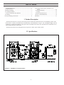
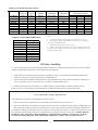
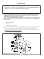
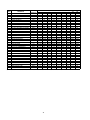
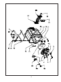
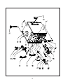
CROWN
Boiler Co
KSZ Series
Oil-Fired Steam Boilers
INSTALLATION INSTRUCTIONS
These instructions must be affixed on or adjacent to the boiler
Models:
• KSZ065
• KSZ075
• KSZ100
• KSZ090
• KSZ125
• KSZ150
• KSZ120
• KSZ175
• KSZ200
WARNING: Improper installation,
adjustment, alteration, service or
maintenance can cause property
damage, injury, or loss of life.
For assistance or additional
information, consult a qualified
installer, service agency or the
oil supplier. Read these instructions carefully before installing.
CROWN
Boiler Co
Manufacturer of Hydronic Heating Products
P.O. Box 14818 3633 I. Street
Philadelphia, PA 19134
1
Tel: (215) 535-8900 • Fax: (215) 535-9736
• www.crownboiler.com
Table of Contents
I. Product Description .............................................................. 1
II. Specifications ........................................................................ 1
III. Before Installing ................................................................... 2
IV. Locating the Boiler ................................................................ 3
V. Air for Combustion & Ventilation ......................................... 3
VI. Venting .................................................................................. 9
VII. System Piping Connections ................................................ 11
VIII. Indirect Water Heater & Tankless Coil
Piping ........................................................... 13
IX. Fuel Line Piping ........................................... 16
X. Wiring .......................................................... 19
XI. Start-up and Checkout .................................. 23
XII. Service & Maintenance ................................ 26
XIII. Parts ............................................................. 31
I Product Description
The KSZ series boiler is a cast iron oil-fired low pressure steam boiler designed for use in closed heating systems. This
boiler must be vented by natural draft into a lined masonry or metal chimney, or Type L vent. An adequate supply of air for
combustion, ventilation and dilution of flue gases must be available in the boiler room. This boiler has connections for use
with an indirect domestic water heater.
The KSZ series boilers are not designed for use in process or other “open” steam systems.
II Specifications
FIGURE 1: GENERAL CONFIGURATION
21
TABLE 1a: GENERAL SPECIFICATIONS
Boiler Model
KSZ065
KSZ075
KSZ100
KSZ090
KSZ125
KSZ150
KSZ120
KSZ175
KSZ200
Number of
Sections
3
3
3
4
4
4
5
5
5
Burner
Input
(G al/hr)
0.65
0.75
1.00
0.90
1.25
1.50
1.20
1.75
2.00
DO E Heating
Capacity
(Btu/hr)
78000
90000
119000
108000
149000
177000
144000
207000
235000
I=B=R Net
Rating (Btu/hr)
56000
68000
89000
81000
112000
133000
108000
155000
176000
I=B=R Net
Rating (Sq. ft)
233
283
370
338
467
554
450
646
733
Dimensions (inches)
"A"
"B"
"C"
16 1/2
8 5/16
6
16 1/2
8 5/16
6
16 1/2
8 5/16
6
21 1/2
10 13/16
7
21 1/2
10 13/16
7
21 1/2
10 13/16
7
26 1/2
13 5/16
8
26 1/2
13 5/16
8
26 1/2
13 5/16
8
Notes:
TABLE 1b: TANKLESS HEATER RATINGS
MODEL
KSZ065
KSZ075
KSZ100
KSZ090
KSZ125
KSZ150
KSZ120
KSZ175
KSZ200
RATING (gpm)
2.25
2.25
2.50
2.50
2.75
3.00
2.75
3.25
3.50
1. Net Ratings are based on piping and pick-up allowances of 1.333.
2. Burner Capacity Rating, GPH is based on #2 oil with a Gross Heating
Value equal to 140000 BTU/Gal.
3. Maximum Working Pressure, Steam -15 PSI.
4. Tankless heater ratings based on 40F inlet water, 140F outlet water, and
190F boiler water. Ratings are also based on 5 minute intermittent draws with
10 minutes between draws.
III Before Installing
1) Safe, reliable operation of this boiler depends upon installation by a professional heating contractor in strict accordance
with this manual and the requirements of the authority having jurisdiction.
•
In the absence of an authority having jurisdiction, installation must be in accordance with this manual and the latest
edition of Installation of Oil Burning Equipment (ANSI/NFPA31).
•
Where required by the authority having jurisdiction, this installation must conform to the latest edition of Standard for
Controls and Safety Devices for Automatically Fired Boilers (ANSI/ASME CSD-1).
2) Make sure that a properly sized chimney is available which is in good condition. Consult the authority having
jurisdiction, Part VI of this manual, and ANSI/NFPA31 for additional information on venting requirements.
Power (“Side Wall”) Venting - Important Note
Two problems arise when any oil-fired appliance is power vented:
1. There is sometimes an accelerated rate of soot buildup on the oil burner cad-cell, spinner etc.
2. There is a potential for severe damage to the side of the structure in the event that the boiler operates at a high smoke level.
This can happen for many reasons, some of which are out of the control of both the installer and appliance manufacturer.
Crown Boiler Company recommends the use of a chimney to vent the KSZ series boilers. If a power venter must be used, it is
the responsibility of the installer and power vent manufacturer to “engineer” the power vent system. CROWN BOILER
COMPANY WILL ASSUME NO RESPONSIBILITY FOR DAMAGE TO SIDING, ETC. FROM A POWER
VENTED OIL-FIRED BOILER. THIS APPLIES REGARDLESS OF THE CAUSE OF THE SOOTING.
32
3) Make sure that the boiler is correctly sized. Use an industry accepted sizing method such as the I=B=R Installation Guide
for Residential Hydronic Heating Systems and I=B=R Heat Loss Calculation Guide (Pub. #H21 or #H22) published by the
Hydronics Institute in Berkeley Heights, NJ.
4) In some cases, boilers installed at altitudes above 2000ft may require a different burner configuration from that at sea level.
Consult the local Crown representative for more information.
IV Locating the Boiler
1) Clearances:
•
Observe the minimum clearances shown below. Except as noted, these clearances apply to all combustible
construction, as well as noncombustible walls, ceilings and doors. Also see Figure 2.
Front – 24”
Left Side – 6” (24” for Boilers Equipped with Float Type Low Water Cut-offs)
Right Side – 6” (24” for Boilers Equipped with Tankless Heaters)
Rear – 6” (24” for boilers connected to indirect water heaters)
Top – 6”
Single Wall Chimney Connector (to combustible construction) - 18”
•
A 24” service clearance from the jacket is recommended from the top of the boiler. This clearance may be
reduced to that shown above; however, servicing the boiler will become increasingly difficult as this clearance is
reduced.
•
A 24” service clearance is required on the left side of KSZ series boilers equipped with float type low water cutoffs. This is to facilitate low water cut-off maintenance.
2) If listed Type L vent is used, follow vent pipe manufacturer recommendations for minimum clearances.
3) Do not install this boiler directly on a combustible surface. Where it is desired to install the KSZ over a non-carpeted
combustible surface, install the boiler on the base shown in Figure 3.
4) Do not install this boiler in a location where gasoline or other flammable vapors or liquids will be stored or used. Do not
install this boiler in an area where large amounts of airborne dust will be present, such as a workshop.
V Air for Combustion and Ventilation
Sufficient fresh air must be supplied for combustion and ventilation. Provisions for combustion and ventilation air for oil
burning equipment must be made in accordance with Section 1.5, Air for Combustion and Ventilation, in the latest edition of
Installation of Oil Burning Equipment (ANSI/NFPA 31).
To ensure an adequate supply of air for combustion, ventilation and flue gas dilution, start by determining whether the boiler
is to be installed in a building of unusually tight construction. A building of unusually tight construction is defined as having
all of the following features:
• Walls and ceilings exposed to outside atmosphere have a continuous water vapor retarder with a rating of 1 perm or
less with openings gasketed and sealed.
• Weather stripping has been added on openable windows and doors.
• Caulking and sealants are applied to areas such as joints around window and door frames, between sole plates and
floors, between wall-ceiling joints, between wall panels, at penetrations for plumbing, electrical, and gas lines, and at
other openings.
43
18* *
6*
6
24
FRONTVIEW
6
SIDE VIEW
* LH SIDE CLEARANCE 24“ FOR FLOAT TYPE LWCO EQUIPPED BOILERS
* * CLEARANCE FROM SINGLE WALL CONNECTOR TO COMBUSTIBLE CONSTRUCTION
FIGURE 2: CLEARANCES
0.47"
Sheet Metal (24 GA or Thicker)
4“ MIN.
Combustible Surfac e
Openings Aligned To Permit Free Air Circulation
Hollow Masonry Blocks
FIGURE 3: INSTALLATION OVER A COMBUSTIBLE FLOOR
54
For Buildings of Other than Unusually Tight Construction
1) Determine whether the boiler is to be installed in a confined space - A confined space is defined as having a volume less
than 50 cubic feet per 1000 BTU/hr input of all appliances installed in that space. To determine whether the boiler room is a
confined space:
a.
b.
c.
Total the input of all appliances in the boiler room in thousands of BTU/hr. Round the result to the next highest
1000 BTU/hr.
Find the volume of the room in cubic feet. The volume of the room in cubic feet is:
Length (ft) x width (ft) x ceiling height (ft)
In calculating the volume of the boiler room, consider the volume of adjoining spaces only if no doors are installed
between them. If doors are installed between the boiler room and an adjoining space, do not consider the volume of
the adjoining space, even if the door is normally left open.
Divide the volume of the boiler room by the input in thousands of BTU/hr. If the result is less than 50, the boiler
room is a confined space.
Example:
A KSZ090 and a water heater are to be installed in a room measuring 6 ft - 3 in x 7 ft with an 8 ft ceiling. The water
heater has an input of 30000 BTU/hr:
Input of KSZ090 = 0.90 Gal/hr x 140000 BTU/Gal = 126000 BTU/hr
Total input in thousands of BTU/hr = (126000 BTU/hr + 30000 BTU/hr)/1000 = 156
Volume of room = 6.25 ft x 7 ft x 8 ft = 350 ft3
350/156 = 2.24. Since 2.24 is less than 50, the boiler room is a confined space.
2) Unconfined Space - Natural infiltration into the boiler room will normally provide adequate air for combustion and
ventilation without additional louvers or openings into boiler room.
3) Confined Space - Provide two openings into the boiler room, one near the floor and one near the ceiling. The top edge of
the upper opening must be within 12” of the ceiling and the bottom edge of the lower opening must be within 12” of the floor
(Figure 4).
•
•
•
Each opening must have a free area of 1 square inch per 1000 BTU/hr input of all fuel burning appliances in the boiler
room. The minimum opening dimension is 3 inches. Minimum opening free area is 100 square inches per opening.
If the total volume of both the boiler room and the room to which the openings connect is less than 50 cubic feet per
1000 BTU/hr of total appliance input, install a pair of identical openings into a third room. Connect additional rooms
with openings until the total volume of all rooms is at least 50 cubic feet per 1000 BTU/hr of input.
The “free area” of an opening takes into account the blocking effect of mesh, grills, and louvers. Where screens are
used, they must be no finer than ¼” (4 x 4) mesh.
For Buildings of Unusually Tight Construction:
1) Openings must be installed between the boiler room and the outdoors or a ventilated space, such as an attic or crawl
space, which communicates directly with the outdoors.
2) Two openings are required. The top edge of the upper opening must be within 12 inches of the ceiling. The bottom
edge of the lower opening must be within 12 inches of the floor.
3) Size openings and ducts as follows:
• Vertical ducts or openings directly outdoors (Figure 5, Figure 6, and Figure 7) - Each opening must have a free
cross sectional area of 1 square inch per 4000 BTU/hr of the total input of all fuel fired appliances in the boiler
room but not less than 100 square inches. Minimum opening size is 3 inches.
• Openings to outdoors via horizontal ducts (Figure 8) - Each opening must have a free cross sectional area of 1
square inch per 2000 BTU/hr of the total input of all fuel fired appliances in the boiler room but not less than 100
square inches. Minimum opening size is 3 inches.
• The “free area” of an opening takes into account the blocking effect of mesh, grills, and louvers. Where screens
are used, they must be no finer than ¼” (4 x 4) mesh.
65
FIGURE 4: BOILER INSTALLED IN CONFINED SPACE,
ALL AIR FROM INSIDE
FIGURE 5: ALL AIR FROM OUTDOORS,
VENTILATED CRAWL SPACE AND ATTIC
76
FIGURE 6: ALL AIR FROM OUTDOORS,
VIA VENTILATED ATTIC
FIGURE 7: ALL AIR FROM OUTDOORS, USING
OPENINGS INTO BOILER ROOM
87
FIGURE 8: ALL AIR FROM OUTDOORS, USING
HORIZONTAL DUCTS INTO BOILER ROOM
98
VI Venting
Vent installation must be in accordance with local building codes, or the local authority having jurisdiction.
Typical vent installation is illustrated by Figure 9. The components of vent installation are the vent connector (breeching),
barometric draft regulator, and chimney.
1) Acceptable Chimneys - The following chimneys may be used to vent a KSZ series boiler:
•
Listed Type L vent - Install in accordance with the manufacturer’s instructions, the terms of its listing, and applicable
codes.
•
Masonry Chimney - The masonry chimney must be constructed in accordance with the latest edition of Standard for
Chimneys, Fireplaces, Vents, and Solid Fuel Burning Appliances (NFPA 211) and lined with a clay liner or other
listed lining system. Do not vent a KSZ series boiler into an unlined chimney.
2) Acceptable Vent Connectors - The following may be used for vent connectors:
•
Listed Type L vent.
•
Single Wall Galvanized Pipe - Use 0.018” (26 gauge) or heavier.
FIGURE 9: TYPICAL VENT SYSTEM
INSTALLATION AND COMPONENTS
3) Chimney and Vent Connector Sizing - See Table 2 for minimum vent connector and chimney sizing. The vent connector
size must not be smaller than the boiler flue collar diameter. Where two or more appliances vent into a common vent, the
cross-sectional area of the common vent should at least equal the area of largest vent plus 50% of the area in the additional
vents.
4) Do not vent this appliance into any portion of a mechanical vent system operating under positive pressure.
5) Do not connect the boiler into a chimney flue serving an open fireplace or other solid fuel appliance.
9
10
6) Prior to boiler installation, inspect chimney for obstructions or other defects and correct as required. Clean chimney as
necessary.
7) Vent pipe should slope upward from the boiler not less than one inch in four feet. No portion of vent pipe should run
downward or have sags. Vent pipe must be securely supported.
8) The vertical section of vent pipe coming off the boiler should be as tall as possible, while still maintaining the proper
clearance from the horizontal vent connector to combustibles and the proper pitch called for in (7) above.
9) Vent pipe should be installed above the bottom of the chimney to prevent blockage.
10) Vent pipe must be inserted flush with inside face of the chimney liner and the space between vent pipe and chimney
sealed tight. A thimble permanently cemented in place can be used to facilitate removal of chimney connector for cleaning.
11) Install the barometric draft regulator in accordance with the regulator manufacturer’s instructions.
12) Secure all joints in the vent connector system with sheet metal screws. This includes the joint between the vent connector
and the boiler collar, as well as the barometric draft regulator. Use at least three screws at each joint.
TABLE 2: MINIMUM RECOMMENDED BREECHING AND
CHIMNEY SIZE
Boiler
Min Breeching
Min. Recommended Chimney Size and Height
Round I.D. (in) Rectangular I.D. (in)
Height (ft)
Model
Dia. (inches)
KSZ065
6
6
8x8
15
KSZ075
6
6
8x8
15
KSZ100
6
6
8x8
15
KSZ090
7
7
8x8
15
KSZ125
7
7
8x8
15
KSZ150
7
7
8x8
15
KSZ120
8
8
8x8
15
KSZ175
8
8
8x8
15
KSZ200
8
8
8x8
15
Power (“Side Wall”) Venting - Important Note
Two problems arise when any oil-fired appliance is power vented:
1. There is sometimes an accelerated rate of soot buildup on the oil burner cad-cell, spinner etc.
2. There is a potential for severe damage to the side of the structure in the event that the boiler operates at a high smoke level.
This can happen for many reasons, some of which are out of the control of both the installer and appliance manufacturer.
Crown Boiler Company recommends the use of a chimney to vent the KSZ series boilers. If a power venter must be used, it is
the responsibility of the installer and power vent manufacturer to “engineer” the power vent system. CROWN BOILER
COMPANY WILL ASSUME NO RESPONSIBILITY FOR DAMAGE TO SIDING, ETC. FROM A POWER
VENTED OIL-FIRED BOILER. THIS APPLIES REGARDLESS OF THE CAUSE OF THE SOOTING.
10
11
VII System Piping
CAUTION
•
INSTALL BOILER SO THAT ALL ELECTRICAL COMPONENTS ARE PROTECTED FROM WATER (DRIPPING,
SPRAYING, RAIN, ETC.) DURING APPLIANCE OPERATION AND SERVICE.
•
OPERATION OF THIS BOILER IN A SYSTEM HAVING SIGNIFICANT AMOUNTS OF DISSOLVED OXYGEN
CAN CAUSE SEVERE HEAT EXCHANGER CORROSION DAMAGE.
Figure 10 shows recommended near boiler Piping for most common types of gravity return steam systems. Additional
information on steam system design may be found in Installation Guide for Residential Hydronic Heating Systems (Pub.
#200) published by the Hydronics Institute in Berkeley Heights, NJ.
One of the primary purposes of this near boiler piping is to separate tiny water droplets from the steam exiting the boiler so
that “dry” steam is sent to the system. If the near boiler piping is not correct, wet steam will enter the system and the following
problems may occur:
•
Short cycling on low water
•
Boiler or system Flooding
•
Hammering
•
Failure to heat one or more radiators
Avoid the common piping mistakes shown in Figure 11. This applies even if the existing boiler has one of the piping mistakes
shown in Figure 11 and appears to be working. If two or more steam mains must be connected to the boiler, connect a
separate take-off for each main into the header between the riser(s) and equalizer. Also note the following points:
1) A size reduction must be made to connect the header to the equalizer. This reduction must be made in the vertical equalizer
line. Do not make this size reduction in the horizontal header.
FIGURE 10: STEAM BOILER PIPING FOR GRAVITY RETURN
11
12
2) One-pipe steam systems require air vents on each radiator, as well as at the end of each main. For the system to work
properly, these vents must be properly installed, sized, and be in good condition. Inspect and replace any defective vents. If
there are no vents at the ends of the mains, install them.
3) Do not attempt to manifold multiple KSZ boilers with gravity returns.
4) For installations with condensate or boiler feed pumps, follow the pump manufacturer’s piping instructions. Such systems
generally do not require Hartford loops.
5) Do not use a check valve in place of, or in addition to, a Hartford loop on a gravity return system.
6) Pipe the fill connection from a clean source of cold water. When the water supply is from a well, make sure that a strainer
is installed in the well system.
Piping Installation
1) Remove parts bag from boiler crate.
2) Install safety valve (spindle must be in vertical position) into the 3/4” tapping on top of the boiler.
3) Pipe the discharge of the safety relief valve to a location where water or steam will not create a hazard or cause property
damage if the valve opens. The end of the discharge pipe must terminate in an unthreaded pipe. If the safety valve discharge is
not piped to a drain, it must terminate at least 6 inches above the floor. The termination of the safety valve discharge piping
must be in an area where it is not likely to become plugged by debris or subjected to freezing.
4) Install drain valve provided into the return piping.
5) Connect system supply and return to boiler. See Figure 10. All KSZ boilers use one supply riser and one return tapping.
DANGER
•
•
•
•
PIPE RELIEF VALVE TO A SAFE LOCATION
DO NOT INSTALL A VALVE IN THE RELIEF VALVE DISCHARGE LINE
DO NOT MOVE RELIEF VALVE FROM FACTORY SPECIFIED
LOCATION
DO NOT PLUG RELIEF VALVE DISCHARGE
WRONG - TAKE-OFF BULLHEADED
INTO TWO MAINS
WRONG - HEADER BULLHEADED
INTO TAKE-OFF AND EQUALIZER
FIGURE 11: COMMON NEAR-BOILER PIPING MISTAKES
12
13
VIII INDIRECT & TANKLESS WATER HEATER PIPING
INDIRECT WATER HEATER PIPING
All KSZ series boilers are equipped with tappings to permit the connection of a Crown Mega-Stor, or other indirect water
heater. In this type of system, hot boiler water is drawn from below the water line and passed through the heat exchanger in
the indirect water heater. This section describes boiler-side piping only. Refer to the indirect water heater instruction manual
for domestic water piping. The components in this system and their functions are as follows:
1) Circulator - Mount the circulator as shown in Figure 12A. The circulator should be located as low and as close to the
boiler as practical. Do not install valves, or other devices having a significant pressure drop, between the boiler and the
circulator inlet. All piping between the boiler and the circulator inlet should be 1”, regardless of the size of the piping
required in the rest of the system. See Figure 17 in Part X for wiring information.
2) “Y” Strainer - Install a “Y” strainer to prevent sediment from accumulating inside the indirect water heater.
3) Check Valve - Prevents gravity circulation through the indirect water heater when the boiler is responding to a call for
heat.
4) Boiler Limit Control - Use a SPST break-on-rise temperature limit control such as the Honeywell L4006A. Do not set the
limit above 180F as doing so may cause the boiler to steam when there is no call for heat. See Figure 17 for wiring
information.
5) Valves and Unions - Install shut-off valves, drain valves, and unions in locations that will facilitate maintenance of the
system. Do not install any valves between the boiler and circulator inlet.
FIGURE 12a: INDIRECT WATER HEATER BOILER-SIDE PIPING
13
14
IMPORTANT
•
Some indirect water heaters may not be suitable for use with a steam boiler. Consult the water heater
manufacturer’s guidelines before installing it in this type of system.
•
Boiler water temperatures and flow rates in this type of system may be considerably lower than those upon which the
water heater manufacturer’s ratings are based. This may result in substantially longer water heater recovery times.
TANKLESS HEATER PIPING
KSZ Series boilers equipped with tankless heaters are supplied with a Honeywell L4006A limit control and a 3/4 NPT well.
For shipping purposes, these components are shipped unmounted. This control is mounted in the 3/4 tapping in the center
of the tankless coil.
Make the piping connections to the coil before installing the L4006A. When making the “OUT” connection, make sure
that the piping is routed so that it will not interfere with the L4006A.
Pipe the heater as shown in Figure 12b. The components in this system and their functions are as follows:
1) Mixing Valve (Required) - During the heating season, the water exiting the tankless heater may be 180 degrees or more.
The mixing valve blends hot water leaving the tankless heater with cold water so as to maintain the hot water supplied to
the fixtures at a fixed temperature. This saves energy, increases the amount of usable hot water available to the
homeowner, and reduces the risk of scalding.
Install a mixing valve with a setting range of approximately 110 to 130F. Follow the manufacturer’s instructions for
installing this valve. Usually a “heat trap” will be required between the coil and the “hot” connection on the mixing valve.
WARNING
A mixing valve does not eliminate the risk of scalding.
•
Set the mixing valve and boiler low limit adjustments as low as possible.
•
Feel water before showering or bathing.
•
If anti-scald or anti-chill protection is required, use devices specifically designed for such service. Install and
maintain these devices in accordance with the manufacturer’s instructions. Do not use the mixing valve as a
substitute for pressure balancing valves or other devices required by plumbing codes to protect against
scalding.
2) Flow Restrictor (Recommended) - If water is drawn from the tankless coil at a rate in excess of the rating in Table 1b, the
temperature of the hot water may be too low to be of use. The use of a flow restrictor will prevent this problem by limiting
the rate at which water can pass through the tankless heater. If a restrictor is used, select one having a rating in GPM
approximately equal to the rating shown in Table 1b. If possible, locate this restrictor at least 3 feet from the tankless heater
inlet so that it is not subjected to excessive temperatures when no water is flowing through the coil.
3) Pressure Relief Valve (Required) - Limits the pressure in the tankless heater and piping. Use an ASME constructed valve
designed for domestic water service, such as the Watts #3L. Note that this is a pressure relief valve, not a T&P valve.
Select a valve with a pressure setting less than or equal to the working pressure marked on the tankless coil. Pipe the
discharge to a safe location using piping the same size as the discharge connection on the valve.
4) Hose Bib Valves (Recommended) - These valves permit the coil to be periodically “backflushed” to remove sediment.
14
15
5) Globe or Ball Valve (Recommended) - Used to adjust the flow through the entire tankless heater system if needed.
6) Unions (Required) - Tankless heaters may require periodic gasket replacement or other maintenance which requires
removal of the heater from the boiler. Install unions anywhere in the tankless heater piping that will facilitate removal of the
heater.
FIGURE 12b: TANKLESS HEATER PIPING
15
16
IX Fuel Line Piping
Fuel line piping design, materials and constructions must be in accordance with local building codes, requirements of the
local authority having jurisdiction, and the latest edition of Installation of Oil-Burning Equipment (ANSI/NFPA 31). Refer
also to the instruction manuals provided with the burner and oil pump.
Depending on the location of the fuel oil storage tank in relation to the oil burner, there are four types of oil piping systems
generally being used:
a) ONE-PIPE GRAVITY SYSTEM - used when a fuel oil storage tank is positioned above an oil burner fuel pump. See
Figure 13. A vertical distance from top of the tank to center line of the pump (Dimension ‘H’) over 8 feet will result in
a pump inlet pressure in excess of the 3-psi limit in NFPA-31.
b) ONE-PIPE LIFT SYSTEM (not recommended) - Used when a fuel oil storage tank is located below an oil burner fuel
pump. See Figure 14. The vertical distance from bottom of the tank to center line of the pump (Dimension ‘H’) must
not exceed that shown in the pump manufacturer’s instructions. Although all oil piping systems must be airtight, onepipe lift systems are particularly susceptible to nuisance lockout problems if the suction line is not completely airtight.
A two-pipe lift system is therefore recommended over a one-pipe lift system.
FIGURE 13: ONE-PIPE GRAVITY SYSTEM
FIGURE 14: ONE-PIPE LIFT SYSTEM
16
17
c) TWO-PIPE GRAVITY SYSTEM (not recommended) - Used when a fuel oil storage tank is located above an oil
burner fuel pump. See Figure 15. A vertical distance from top of the tank to center line of the pump (Dimension ‘H’)
over 8 feet will result in a pump inlet pressure in excess of the 3-psi limit in NFPA-31. This type of system should be
converted to a one-pipe gravity system, as doing so will result in lower inlet line flow and longer filter life.
d) TWO-PIPE LIFT SYSTEM - used when a fuel oil storage tank is located below an oil burner fuel pump suction port. See
Figure 16. The vertical distance from bottom of the tank to center line of the pump (Dimension ‘H’) must not exceed that
shown in the pump manufacturer’s instructions. Distance ‘H’ allowed is reduced by number of fittings, filters and
valves installed in the line.
FIGURE 15: TWO-PIPE GRAVITY FEED SYSTEM
FIGURE 16: TWO-PIPE LIFT SYSTEM
17
18
Once the type of system has been selected, observe the following:
1) Fuel line piping must be airtight. Do not use compression type fittings for tubing connections in fuel line piping. Use
only listed flare type fittings. Cast iron threaded fittings shall not be used for wrought iron or steel piping connections.
2) Piping shall be substantially supported and protected against physical damage and corrosion where required.
3) Refer to supplied oil pump instruction manual for proper connections. On one-pipe systems, ensure that the fuel pump
return port plug is tightened securely.
4) Some fuel pumps, such as the Suntec A and B series, are supplied with a loose bypass plug which must be installed on
two-pipe systems. If such a plug is supplied, install it as shown in the pump manufacturers’s instructions. Do not install this
bypass plug on one-pipe systems as pump seal damage will result.
5) Do not use check valves, especially on gravity feed systems.
6) Do not use Teflon tape for threaded connections. Use a listed non-hardening thread sealant instead.
7) Attach required piping between burner fuel pump and fuel oil storage tank. Install one fuel shut-off valve near the storage
tank and second fuel shut-off valve near the oil burner fuel pump. Use heavy wall copper tubing in a continuous run. On
two-pipe systems, the return line should terminate 3” - 4” above suction line depth within the storage tank. Refer to the
pump manufacturer’s instructions for tube sizing information.
8) All systems require an oil filter. On KSZ065 and KSZ075 boilers, the use of a Garber cartridge type filter is
recommended.
9) Use only #2 Fuel Oil with physical and chemical characteristics meeting the requirements of ASTM D-396.
18
19
X Wiring
WARNING
All wiring and grounding must be done in accordance with the authoity having jurisdiction or, in the absence of such
authority, with the National Electric Code (ANSI/NFPA70).
1) 120 Volt Wiring - Provide the boiler with its own 15A branch circuit with fused disconnect. How the 120 volt connections
are made depends upon the type of low water cut-off supplied with the boiler.
For boilers equipped with Hydrolevel CG450 - 120 Volt connections are made inside the CG450:
•
•
•
Connect Hot (“black”) to terminal #1 in CG450
Connect Neutral (“white”) to terminal #2 in CG450
Connect Ground (“green” or bare) to green screw on case of CG450
For boilers equipped with McDonnell & Miller #67 low water cut-offs - 120 Volt connections are made inside the
junction box mounted on the low water cut-off:
• Connect Hot (“black”) to black pigtail in junction box
• Connect Neutral (“white”) to white pigtail in junction box
• Connect Ground (“green” or bare) to green screw in junction box
2) Thermostat Wiring - Follow thermostat manufacturer instructions. To insure proper thermostat operation, avoid installation in areas of poor air circulation, hot spots (near any heat source or in direct sunlight), or cold spots (outside walls,
walls adjacent to unheated areas, locations subject to drafts). Provide Class II circuit between thermostat and boiler.
Connect thermostat wire leads to terminals “T” and “T” on the burner primary control.
3) Optional Tankless Heater Wiring - Install the L4006A with the 3/4 NPT well in the 3/4 tapping in the center of the coil plate.
Make sure that the sensing bulb of this control is fully bottomed out in the well. Route the wire harness from this control
to the “T” and “T” (thermostat) terminals on the burner primary control so that they are in parallel with the space heating
thermostat.
Indirect Water Heater Wiring
Figure 17 shows field wiring for an indirect water heater. A Honeywell R845A or equivalent DPST relay and transformer is
required. The high limit described in Part VIII must also be supplied by the installer. A call for heat from the indirect water
heater thermostat will energize the relay making both sets of contacts. One set of these contacts then energizes the circulator.
The other set of contacts will make the “T” and “T” contacts on the burner primary control, firing the burner. If the boiler
water temperature exceeds the high limit setting of 180F, the high limit will open the “T” - “T” circuit and the burner will shut
down.
If there is a call for space heat, the heating thermostat will make the “T”-”T” circuit and the boiler will fire without regard to
the status of the indirect water heater. The low water cut-off and pressure limit control will interrupt 120 volt power to the
burner in the event of a low water or excessive pressure condition.
19
20
FIGURE 17: INDIRECT WATER HEATER FIELD WIRING
Feeder Wiring for Boilers Equipped with Hydrolevel CG450 Low Water Cut-offs
1) Using Hydrolevel VXT-120 feeder - Do not alter factory boiler wiring. Connect VXT-120 to CG450 as follows:
•
•
Connect the BLACK lead on the feeder to terminal A on the CG450.
Connect the WHITE lead on the feeder to terminal 2 on the CG450.
2) Using McDonnell & Miller WF2-U-120 feeder - Do not alter factory boiler wiring. Connect WF2-U-120 to CG450A as
follows:
•
•
•
Connect terminal 1 on the feeder to terminal A on the CG450.
Connect terminal 2 on the feeder to terminal 2 on the CG450.
Connect terminal 3 on the feeder to terminal 1 on the CG450.
Feeder Wiring for Boilers Equipped with McDonnell & Miller Low Water Cut-offs
Figures 18a and 18b show feeder wiring for McDonnell & Miller #101A, McDonnell & Miller WF2-U-120 and Hydrolevel VXT120 feeders on boilers equipped with #67 low water cut-offs.
20
21
FIGURE 18a: WIRING MCDONNELL & MILLER 101A-120 OR HYDROLEVEL VXT-120 FEEDER TO
BOILER EQUIPPED WITH #67 L.W.C.O.
FIGURE 18b: WIRING MCDONNELL & MILLER WF2-U-120
FEEDER
21
22
L4006A LIMIT CONTROL
(TANKLESS-EQUIPPED BOILERS ONLY)
L1
INTERRUPTED
24 VOLT THERMOSTAT
INTERMITTENT
BURNER MOTOR
LIMIT
VALVE
CAD
CELL
L2
NOTE: BURNER WIRING SHOWN IS FOR BECKETT
AFG BURNERS. CONSULT BURNER INSTRUCTION
MANUAL FOR OTHER BURNERS
FIGURE 19: WIRING (MCDONNELL & MILLER #67 LWCO)
L4006A LIMIT CONTROL
(TANKLESS-EQUIPPED BOILERS ONLY)
L1
INTERRUPTED
24 VOLT THERMOSTAT
INTERMITTENT
BURNER MOTOR
LIMIT
VALVE
L2
CAD
CELL
NOTE: BURNER WIRING SHOWN IS FOR BECKETT
AFG BURNERS. CONSULT BURNER INSTRUCTION
MANUAL FOR OTHER BURNERS
FIGURE 20: WIRING (HYDROLEVEL CG450 LWCO)
2322
XI Start-up and Checkout
WARNING
•
•
•
•
NEVER ATTEMPT TO FILL A HOT EMPTY BOILER.
MAKE SURE THAT THE AREA AROUND THE BOILER IS CLEAR AND FREE FROM
COMBUSTIBLE MATERIALS, GASOLINE, AND OTHER FLAMMABLE VAPORS AND LIQUIDS.
SAFE RELIABLE OPERATION OF THIS BOILER REQUIRES THAT THE BURNER BE CHECKED
AND ADJUSTED BY A QUALIFIED OIL SERVICEMAN USING COMBUSTION TEST
INSTRUMENTS.
FAILURE TO PERFORM ALL OF THE CHECKS OUTLINED IN THE FOLLOWING PROCEDURE
COULD RESULT IN UNRELIABLE OPERATION, DAMAGE TO THE BOILER NOT COVERED
UNDER WARRANTY, PROPERTY DAMAGE, OR UNSAFE OPERATION.
Use the following procedure for initial start-up of the boiler:
1) Ensure that the boiler is filled to the normal water level.
2) Verify that the vent system is complete and free of obstructions prior to start-up of the boiler.
3) Inspect all wiring for loose or uninsulated connections, proper size fuses installed, etc.
4) Verify that oil tank is filled with #2 fuel oil meeting ASTM D396 specifications, oil piping has been tested and is air tight,
and shut-off valve(s) are closed.
5) Check initial settings of oil burner air band and air shutter, head setting etc. and readjust if needed. See Table 3 for setup
and combustion data pertaining to a particular boiler/ burner combination.
6) Attach plastic hose to oil pump vent fitting and provide a container to catch oil during oil pump bleeding procedure.
7) Install 0-200 PSI pressure gauge into oil pump gauge port.
8) Open all oil line shut-off valves.
9) Open flame observation port cover on burner swing door to see flame.
10) Adjust system thermostat to highest setting.
11) Set pressure limit control to suit individual requirements of the installation. For most steam systems, the cut-in pressure
should be set at 0.5 psi with a 1 psi differential.
12) Turn the line service switch to “ON” position.
13) Crack open vent fitting on the oil pump and allow burner to run until a solid oil stream, free of air bubbles, flows for 15
seconds into container. As the vent fitting is closed, the burner should fire and flame should be visible through observation
port immediately (or after prepurge timing has expired, if a burner is so equipped). Refer to burner instructions for more
details.
14) Immediately upon firing the boiler, check the smoke level. If the smoke level is in excess of a #1, open the air adjustment
to bring the smoke level below a #1.
15) Make sure that the oil pressure matches that shown in Table 3 for the burner supplied. Adjust pressure if required.
16) Check the vacuum at the inlet of the fuel pump. Make sure that the vacuum does not exceed the fuel pump manufacturer’s
limit (consult the pump manufacturer’s instructions).
17) Close the flame observation cover.
18) After chimney has warmed-up to operating temperature, adjust barometric draft regulator for a draft of -0.02 inch w. c.
over the fire.
19) Check the CO2 and confirm that it is between the minimum and maximum limits shown in Table 3. Adjust if necessary.
20) Verify that the smoke level still does not exceed #1 and that the draft over fire is -0.02 inch w.c.
21) Turn off the burner and remove pressure gauge. Install and tighten gauge port plug, than restart the burner.
22) Check for clean cutoff of the burner. Air in the oil line between fuel pump and nozzle will compress, while burner is
running, and expand, when burner shuts off, causing oil line pressure to drop and nozzle drip after burner stops. Cycle burner
on and off 5 to 10 times to purge air completely.
23) Check thermostat operation by raising or lowering its set point as required, cycling burner on and off.
23
24
24) Verify primary control operation and safety features according to procedure outlined in the instructions furnished with
control.
25) Check pressure limit control operation. Jump thermostat terminals and allow burner to run until boiler pressure exceeds
cut-in pressure plus the differential. The burner should shut down.
26) Check low water cut-off operation. With the thermostat still jumped, fire the boiler and crack the boiler drain valve so that
water is slowly drained from the boiler. Confirm that the burner shuts down before the water level drops below the bottom of
the sight glass. Do not permit the boiler to fire without water visible in the sight glass. Add water to the boiler and
confirm that the burner restarts. Remove thermostat jumper and reconnect thermostat upon check completion.
27) After the boiler has operated for approximately 30 minutes, check the boiler and heating system for leaks. Repair any
leaks found at once.
28) After the above checks have been completed, leave thermostat(s) at desired setting. Leave all instructions provided with
the boiler with owner or in boiler room, displayed near boiler.
29) After new boiler has been installed and put into continuous operation for several days, clean the boiler of oil, grease,
sludge, and other contaminants that may have been present in existing piping. This will prevent unsteady water line and water
carry over into supply main. The boiler boil-out should be done as follows:
a)
Turn off the burner.
b) Drain water from boiler until about one inch of water is visible in gauge glass.
c)
Run a hose or temporary piping from the boiler drain valve to a location where hot water can be safely discharged.
Drain approximately five gallons of water from the boiler and mix-in an appropriate amount of an approved boil-out
compound. Remove safety valve and refill the boiler with prepared solution through funnel. Replace safety valve.
d) Run a hose or temporary piping from the 1-1/2” skimmer tap on the upper rear section to a location where hot water
can be safely discharged.
e)
Start the burner. Run boiler for several hours, boiling the water, without generating steam pressure. Open the water
feed valve sufficiently to allow a slight overflow of water through the skimmer tapping drain line. Continue boiling
until water coming out is clear.
f)
Turn off the burner. Drain hot water from boiler through boiler drain valve to a location where hot water can be
safely discharged. Refill the boiler to normal water line level. If water in the gauge glass does not look clear, repeat
above boil-out procedure again until water clears out.
g) Reinstall safety valve and related piping.
h) Conduct pH and Alkalinity test of water in the system. The pH reading should be in 7 to 11 range.
NOTE
When substantial amount of make-up water is used due to lost condensate, or when make-up water is hard or corrosive,
water treatment is required. Contact qualified water treatment company for recommended water treatment compounds
and procedure.
CAUTION
ATTEMPTS TO USE BURNERS OR BURNER CONFIGURATIONS OTHER THAN THOSE SHOWN IN
TABLE 3 COULD RESULT IN RELIABILITY PROBLEMS, DAMAGE TO THE BOILER NOT COVERED
UNDER WARRANTY, PROPERTY DAMAGE, OR UNSAFE OPERATION.
24
25
TABLE 3a: BECKETT BURNER CONFIGURATION AND SETUP DATA
BOILER MODEL
KSZ065
BURNER MODEL
AIR TUBE COMBO.
HEAD TYPE
STATIC PLATE
LOW FIRING RATE
BAFFLE
INSERTION LENGTH
PITCH ANGLE
STANDARD
NOZZLE
ALTERNATE
NOZZLE
PUMP PRESS (psi)
HEAD SETTING
STARTING:
SHUTTER SETTING
BAND SETTING
DRAFT OVER FIRE
(in w.c.)
MAX. SMOKE
(bacharach scale)
FLUE CO2 (%)
MIN.
MAX
PREPURGE
IGNITION MODE
AFG
70MMAQ
L1
3 3/8
BECKETT
#3708
2 1/4
2
HAGO
0.55/60B
DEL.
0.55/60W
140
NA
KSZ075
KSZ100
KSZ090
KSZ125
KSZ150
KSZ120
KSZ175
KSZ200
AFG
AFG
AFG
AFG
70MMAQ 70MMAQ 70MMAQ 70MDAQ
L1
L1
L1
V1
3 3/8
3 3/8
3 3/8
2 3/4
BECKETT
NONE
NONE
NONE
#3708
2 1/4
2 1/4
2 1/4
2 1/4
2
2
2
2
HAGO
HAGO
DEL.
HAGO
0.65/60B 0.85/60B 0.75/60B 1.00/60B
DEL.
DEL.
HAGO
DEL.
0.65/60W 0.85/60W 0.75/60B 1.00/60B
140
140
140
140
NA
NA
NA
0
AFG
70MDAQ
V1
2 3/4
AFG
70MLAQ
V1
NONE
AFG
70MLAQ
V1
NONE
AFG
70MLAQ
V1
NONE
NONE
NONE
NONE
NONE
2 1/4
2
HAGO
1.25/60B
DEL.
1.25/60B
140
0
2 1/4
2
HAGO
0.90/60B
DEL.
0.90/60B
175
0
2 1/4
2
HAGO
1.35/45B
DEL.
1.35/45B
175
3
2 1/4
2
HAGO
1.50/45B
DEL.
1.50/45B
175
4
1
1
10
2
5
2
7
0
10
0.5
10
6
8
1
6
6
8
4
-0.02
-0.02
-0.02
-0.02
-0.02
-0.02
-0.02
-0.02
-0.02
#1
#1
#1
#1
#1
#1
#1
#1
#1
11.0
12.5
11.0
12.5
11.0
12.5
11.0
12.5
11.0
12.5
11.0
12.5
None
11.0
12.5
KSZ150 KSZ120
KSZ175
KSZ200
11.0
11.0
12.5
12.5
15 SECONDS
INTERUPTED
TABLE 3b: CARLIN BURNER CONFIGURATION AND SETUP DATA
KSZ065
BURNER MODEL
STANDARD
NOZZLE
PUMP PRESS (psi)
HEAD BAR
STARTING
BAND SETTING
DRAFT OVER FIRE
(in w.c.)
MAX. SMOKE
(bacharach scale)
FLUE CO2 (%)
MIN.
MAX
PREPURGE
IGNITION MODE
KSZ075
KSZ100
EZ-1HP
EZ-1HP
EZ-1HP
DEL.
HAGO
HAGO
0.55/70B 0.60/60ES 0.85/60B
150
150
150
0.50
0.60-0.65 0.85-1.00
KSZ090
EZ-1HP
DEL.
0.75/60A
150
0.75
KSZ125
EZ-1HP
EZ-1HP
EZ-1HP
DEL.
HAGO
HAGO
1.00/60A 1.25/60B 1.00/60B
150
150
150
0.85-1.00 1.10-1.25 0.85-1.00
0.55
0.60
0.75
0.75
-0.02
-0.02
-0.02
-0.02
-0.02
#1
#1
#1
#1
#1
11.0
12.5
11.0
12.5
11.0
12.5
11.0
12.5
25
26
EZ-2HP
DEL.
1.50/60A
150
1.50
0.90
1.75
-0.02
-0.02
-0.02
#1
#1
#1
11.0
12.5
11.0
12.5
1.00-1.10 1.25-1.35
11.0
11.0
12.5
12.5
NONE
INTERRUPTED
TABLE 3c: RIELLO BURNER CONFIGURATION AND SETUP DATA
KSZ065
BURNER MODEL
STANDARD
NOZZLE
PUMP PRESS (psi)
TURBULATOR
AIR
SHUTTER SETTING
DRAFT OVER FIRE
(in w.c.)
MAX. SMOKE
(bacharach scale)
FLUE CO2 (%)
MIN.
MAX
KSZ125
KSZ150 KSZ120
KSZ175
KSZ200
40F5
DEL
0.85/60W
150
2
40F5
DEL.
1.00/60A
150
4
40F10
DEL
1.25/60B
150
1
40F10
HAGO
1.35/45B
150
1.5
40F10
DEL
1.65/45B
150
2
2.60
2.85
4
3
3
3.8
-0.02
-0.02
-0.02
-0.02
-0.02
-0.02
#1
#1
#1
#1
#1
#1
11.0
12.5
11.0
12.5
11.0
12.5
11.0
12.5
11.0
12.5
11.0
12.5
KSZ075
KSZ100
40F5
DEL
0.60/60A
150
0
KSZ090
XII Service and Maintenance
The following procedure should be performed on a weekly basis:
For boilers equipped with a #67 low water cut-off, blow down the low water cut-off following the instructions on the yellow
sticker adjacent to the low water cut-off. During this blow down, the low water cutoff should shut down the burner. If it does
not, the low water cut-off should be replaced immediately.
The following procedure should be performed on an annual basis:
1) Turn off electrical power and oil supply to the boiler.
2) Inspect the low water cut-off:
•
•
For Hydrolevel CG450 low water cut-offs - Remove and inspect the probe for scale and sediment buildup. Clean any
sediment or scale from the probe with a scouring pad or steel wool. Consult the Hydrolevel CG450 manual for any
additional maintenance information. Test the low water cut-off before placing the boiler back into service.
For McDonnell & Miller #67 low water cut-offs - Remove and inspect switch and float mechanism. Inspect float
bowl for mud accumulation. Clean as required. Replace the switch and float mechanism every five years or 100,000
cycles. Consult the McDonnell and Miller #67 manual for any additional maintenance information. Test the low
water cut-off before placing the boiler back into service.
26
27
3) Allow the boiler to cool to room temperature and drain the boiler. Remove the 1-1/2” plug from the unused return tapping.
Use a flashlight to inspect the bottom row of pushnipples for accumulated scale or mud. If a significant amount is present, use
the following procedure to clean the inside of the heat exchanger:
a) Temporarily install a 1-1/4” inch or larger full port ball valve in place of the 1-1/2” plug. Temporarily pipe the outlet
of this valve to a location where hot water and steam can be safely discharged.
b) Make sure that this valve is closed and that the water level is at the normal water line.
c) If a king valve is present in the steam main takeoff, close it. Alternatively, temporarily replace enough of the
vents on the mains and/or radiators with plugs so that 2-5 psi can be developed when the boiler is fired.
d) Fire the boiler and allow it to steam until 2-5 psi is registered on the gauge.
e) Turn off the burner and immediately fully open the 1-1/4” valve.
f) Allow the boiler to blow down until either the water runs clear or the water level reaches the bottom of the gauge
glass.
g) Allow all parts of the boiler to cool to room temperature. Drain the boiler completely and remove the 1-1/4” valve.
h) If significant mud or scale is still present in the bottom of the boiler, repeat steps (b) through (g) until all mud or
scale is removed.
i) Once all mud or scale is removed, replace the 1-1/4” valve and temporary blow-down piping with the standard plug.
After all parts of the boiler are at room temperature, refill the boiler to the normal water line.
NOTE
A large accumulation of mud or scale in the bottom of the heat exchanger is usually a sign of excessive feedwater make-up.
Such accumulations can cause severe heat exchanger damage. If mud or scale accumulations are found:
•
•
Make sure that all vents are in working order. Vents should not permit any passage of steam or water.
Check all steam and return piping for leaks. Be aware that buried return piping can leak and go undetected
during normal operation.
4) Clean the boiler flue passages as follows:
a) Remove vent connector and piping.
b) Remove barometric draft regulator.
c) Remove top jacket panel to gain access to boiler flue collector.
d) Unscrew four wing nuts and remove canopy retaining carriage bolts, lift off the canopy and ceramic fiber sealing
strips.
e) Unplug the burner, disconnect the oil lines (if the pump is hard piped), and remove the two 5/16” bolts securing the
burner door. Open the burner swing door.
f) Thoroughly brush boiler flueways from the top and diagonally between casting pin rows. Be careful when brushing the
rear passage not to damage the rear target wall insulation.
g) Vacuum soot and debris from combustion chamber.
h) Check condition of rear target wall insulation, combustion chamber liner, and burner door insulation; replace if
required.
i) Check burner head for signs of deterioration. Clean the head of any deposits.
j) Close burner door, reinstall 5/16” bolts, reconnect fuel oil and electrical lines.
k) Installation of boiler canopy, jacket top panel barometric draft regulator and breeching piping is done in reverse order
of removal. Make sure canopy is sealed tight to the casting; replace ceramic fiber sealing strips as needed. All vent
piping joints must be flue gas leak free and secured with sheet metal screws.
27
28
IMPORTANT
•
CLEAN THE BOILER EVEN IF THERE ARE NO SIGNIFICANT SOOT DEPOSITS. FAILURE TO
REMOVE ALL SULFUR AND ASH DEPOSITS ANNUALLY CAN CAUSE SEVERE CORROSION
DAMAGE.
•
WHEN CLEANING THE REAR FLUE PASSAGE, BE CAREFUL NOT TO PUSH THE BRUSH TOO
FAR BEYOND THE BOTTOM OF THE PINS. DOING SO MAY DAMAGE THE TARGET WALL.
3) Inspect the vent system:
a) Make sure that the vent system is free of obstructions and soot.
b) Make sure that all vent system supports are intact.
c) Inspect joints for signs of condensate or flue gas leakage.
d) Inspect venting components for corrosion or other deterioration. Replace any defective vent system components.
4) Service the oil burner:
a) Replace oil nozzle with identical make and model (see Table 3).
b) Inspect the electrodes. Replace if they are deteriorated. Make sure that the electrode position is set according to the
burner manufacturer’s instructions.
c) Remove and clean fuel pump strainer.
d) Remove any accumulations of dust, hair, etc. from the air shutter, blower wheel, and other air handling parts of the
burner.
5) Replace the fuel oil line filter element and gaskets.
6) Inspect all oil piping and fittings for kinks and leaks. Repair any found.
7) Inspect the system piping, tankless coil and tankless coil cover gaskets, and boiler plugs for water leaks. Repair any leaks
found immediately.
8) Verify operation of relief valve by manually lifting lever; replace relief valve immediately if valve fails to relieve pressure.
9) Open fuel line shut-off valve(s) and restore electrical power to the boiler.
10) Fire the boiler and check it out using the procedure outlined in “Start-up and Checkout” . This must include checking the
burner adjustments using instruments. Check for proper operation of all controls.
TANKLESS HEATER MAINTENANCE
•
During the warm months, make sure that the water level in the boiler is 23-1/2 to 25 inches above the floor. Failure to do
this may result in inadequate hot water and/or steaming when there is no call for heat.
•
Maintain the mixing valve in accordance with the valve manufacturer’s instructions.
28
29
Important Product Safety Information
Refractory Ceramic Fiber Product
Warning:
The Parts list designates parts that contain refractory ceramic fibers (RCF).
RFC has been classified as a possible human carcinogen. When exposed to
temperatures about 1805°F, such as during direct flame contact, RFC changes
into crystalline silica, a known carcinogen. When disturbed as a result of
servicing or repair, these substances become airborne and, if inhaled, may be
hazardous to your health.
AVOID Breathing Fiber Particulates and Dust
Precautionary Measures:
Do not remove or replace RCF parts or attempt any service or repair work
involving RCF without wearing the following protective gear:
1. A National Institute for Occupational Safety and Health (NIOSH)
approved respirator
2. Long sleeved, loose fitting clothing
3. Gloves
4. Eye Protection
•
•
•
•
Take steps to assure adequate ventilation.
Wash all exposed body areas gently with soap and water after contact.
Wash work clothes separately from other laundry and rinse washing
machine after use to avoid contaminating other clothes.
Discard used RCF components by sealing in an airtight plastic bag. RCF
and crystalline silica are not classified as hazardous wastes in the United
States and Canada.
First Aid Procedures:
•
•
•
•
If contact with eyes: Flush with water for at least 15 minutes. Seek
immediate medical attention if irritation persists.
If contact with skin: Wash affected area gently with soap and water.
Seek immediate medical attention if irritation persists.
If breathing difficulty develops: Leave the area and move to a location
with clean fresh air. Seek immediate medical attention if breathing
difficulties persist.
Ingestion: Do not induce vomiting. Drink plenty of water. Seek
immediate medical attention.
29
30
Installation Notes And Service Log
30
31
QUANTITY PER BOILER OR CROWN P.N.
175
200
75
100
90
125
150
120
65
2800135 2800135 2800135 2800145 2800145 2800145 2800155 2800155 2800155
1 ea.
1 ea.
1 ea.
1 ea.
1 ea.
1 ea.
1 ea.
1 ea.
1 ea.
1 ea.
1 ea.
1 ea.
1 ea.
1 ea.
1 ea.
1 ea.
1 ea.
1 ea.
1 ea.
1 ea.
1 ea.
2 ea.
2 ea.
2 ea.
3 ea.
3 ea.
3 ea.
2 ea.
2 ea.
2 ea.
3 ea.
3 ea.
3 ea.
4 ea.
4 ea.
4 ea.
2 ea.
2 ea.
2 ea.
3 ea.
3 ea.
3 ea.
4 ea.
4 ea.
4 ea.
2 ea.
2 ea.
2 ea.
2 ea.
2 ea.
2 ea.
2 ea.
2 ea.
2 ea.
2 ea.
2 ea.
2 ea.
2 ea.
2 ea.
2 ea.
2 ea.
2 ea.
2 ea.
1 ea.
1 ea.
1 ea.
1 ea.
1 ea.
1 ea.
1 ea.
1 ea.
1 ea.
2 ea.
2 ea.
2 ea.
2 ea.
2 ea.
2 ea.
2 ea.
2 ea.
2 ea.
10 ea.
10 ea.
10 ea.
10 ea.
10 ea.
10 ea.
10 ea.
10 ea.
10 ea.
4 ea.
4 ea.
4 ea.
4 ea.
4 ea.
4 ea.
4 ea.
4 ea.
4 ea.
1 ea.
1 ea.
1 ea.
1 ea.
1 ea.
1 ea.
1 ea.
1 ea.
1 ea.
1 ea.
1 ea.
1 ea.
1 ea.
1 ea.
1 ea.
1 ea.
1 ea.
1 ea.
1
*
*
*
*
*
2
3
4
5
6
7
8
9
COMPLETE HEAT EXCHANGER ASSY.
FRONT SECTION
REAR SECTION
INTERMEDIATE SECTION
LOWER PUSHNIPPLE
UPPER PUSHNIPPLE
BURNER SWING DOOR HINGE
FRONT SECTION HINGE
SWING DOOR INSULATION†
5/16-18 X 1-1/2 HX HEAD CAP SCREW
5/16 FLAT WASHER
5/16-18 X 1 HX HEAD CAP SCREW
FLAME INSPECTION COVER
5/16-18 X 3/4 HEX HEAD CAP SCREW
QTY. OR
CROWN P.N.
1 ea.
275051
275062
275055
275070
275075
275030
275035
270021
900415
900102
900410
270022
900400
10
11
12
20
21
22
23
24
25
TARGET WALL (REPLACEMENT KIT)†
REFRACTORY BLANKET†
SWING DOOR
1/2" x 1" SEALING STRIP†
FLUE COLLECTOR
1/4-20 x 3" CARRIAGE BOLT
1/4-20 x 3-1/2" CARRIAGE BOLT
1/4" USS FLAT WASHER
1/4-20 WING NUT
270025
1 ea.
270020
900145
1 ea.
900126
900127
90-215
900125
1 ea.
275003
1 ea.
4.0 ft
270123
2 ea.
2 ea.
4 ea.
4 ea.
1 ea.
275003
1 ea.
4.0 ft
270123
2 ea.
2 ea.
4 ea.
4 ea.
1 ea.
275003
1 ea.
4.0 ft
270123
2 ea.
2 ea.
4 ea.
4 ea.
1 ea.
275004
1 ea.
4.8 ft
270124
2 ea.
2 ea.
4 ea.
4 ea.
1 ea.
275004
1 ea.
4.8 ft
270124
2 ea.
2 ea.
4 ea.
4 ea.
1 ea.
275004
1 ea.
4.8 ft
270124
2 ea.
2 ea.
4 ea.
4 ea.
1 ea.
275005
1 ea.
5.7 ft
270125
2 ea.
2 ea.
4 ea.
4 ea.
1 ea.
275005
1 ea.
5.7 ft
270125
2 ea.
2 ea.
4 ea.
4 ea.
1 ea.
275005
1 ea.
5.7 ft
270125
2 ea.
2 ea.
4 ea.
4 ea.
30
FRONT TANKLESS HEATER GASKET
270001
1 ea.
1 ea.
1 ea.
1 ea.
1 ea.
1 ea.
1 ea.
1 ea.
1 ea.
31
33
34
FNT. HEATER OPENING COVER PLATE
3/8-16 X 7/8 HX HEAD CAP SCREW
3/8 USS FLAT WASHER
270003
900450
90-036
1 ea.
14 ea.
14 ea.
1 ea.
14 ea.
14 ea.
1 ea.
14 ea.
14 ea.
1 ea.
14 ea.
14 ea.
1 ea.
14 ea.
14 ea.
1 ea.
14 ea.
14 ea.
1 ea.
14 ea.
14 ea.
1 ea.
14 ea.
14 ea.
1 ea.
14 ea.
14 ea.
35
36
37
38
KSZ COIL GASKET
KSZ TANKLESS COIL
KSZ BLANK COIL PLATE
123871A LONG WELL
280001
280002
280003
35-1020
1 ea.
1 ea.
1 ea.
1 ea.
1 ea.
1 ea.
1 ea.
1 ea.
1 ea.
1 ea.
1 ea.
1 ea.
1 ea.
1 ea.
1 ea.
1 ea.
1 ea.
1 ea.
1 ea.
1 ea.
1 ea.
1 ea.
1 ea.
1 ea.
1 ea.
1 ea.
1 ea.
1 ea.
1 ea.
1 ea.
1 ea.
1 ea.
1 ea.
1 ea.
1 ea.
1 ea.
KEY #
DESCRIPTION
† SEE PAGE 30 FOR WARNING REGARDING THE HANDLING OF PARTS THAT CONTAIN REFRACTORY CERAMIC FIBERS.
31
32
32
33
40
41
*
43
44
45
46
47
48
49
50
51
52
*
54
55
56
QTY. OR
CROWN P.N.
LEFT SIDE JACKET PANEL
1 ea.
RIGHT SIDE JACKET PANEL
1 ea.
REAR JACKET PANEL
270220
TOP JACKET PANEL
1 ea.
FRONT PANEL
270210
UPPER FRONT PANEL
270215
#10 X 1/2" SHEET METAL SCREW
90-212
5/16-18 X 1/2 PAN HEAD SCREW
900420
CG450 PROBE LOW WATER CUT-OFF
450450
#67 LOW WATER CUT-OFF (OPTIONAL)
400677
PRESSURE LIMIT CONTROL (PA404A)
35-5020
JUNCTION BOX
96-001
8-32 X 1/2 SCREW
90-052
8-32 HEX NUT
90-053
TWIST RECEPTICAL
96-010
TWIST RECEPTICAL COVER
96-019
PRESSURE GAUGE
95-070
60
60
60
*
*
BECKETT BURNER ASSY. (NOTE #1)
CARLIN BURNER ASSY. (NOTE #1)
RIELLO BURNER ASSY. (NOTE #1)
BURNER CORD ASSY. (BCKT./CARLIN)
BURNER CORD ASSY. (RIELLO)
1 ea.
1 ea.
1 ea.
960275
130511
130521
130512
130522
130513
130523
130514
130524
130515
130525
130516
130526
130517
130527
130518
130519
1 ea.
1 ea.
1 ea.
1 ea.
1 ea.
1 ea.
1 ea.
1 ea.
1 ea.
61
62
5/16-18 X 1-1/4 STUD
5/16-18 HEX NUT
90-012
90-010
3 ea.
3 ea.
3 ea.
3 ea.
3 ea.
3 ea.
3 ea.
3 ea.
3 ea.
3 ea.
3 ea.
3 ea.
3 ea.
3 ea.
3 ea.
3 ea.
3 ea.
3 ea.
70
71
72
3/4" POP SAFETY (15 psi)
STRAIGHT BRASS PIGTAIL
GLASS SET
95-079
95-060
950078
1 ea.
1 ea.
1 ea.
1 ea.
1 ea.
1 ea.
1 ea.
1 ea.
1 ea.
1 ea.
1 ea.
1 ea.
1 ea.
1 ea.
1 ea.
1 ea.
1 ea.
1 ea.
1 ea.
1 ea.
1 ea.
1 ea.
1 ea.
1 ea.
1 ea.
1 ea.
1 ea.
73
LOW LIMIT (L4006A2015)
35-3510
1 ea.
1 ea.
1 ea.
1 ea.
1 ea.
1 ea.
1 ea.
1 ea.
1 ea.
3/4" BOILER DRAIN
95-041
1 ea.
1 ea.
1 ea.
1 ea.
1 ea.
1 ea.
1 ea.
1 ea.
1 ea.
KEY #
*
DESCRIPTION
65
270233
2702235
1 ea.
270243
1 ea.
1 ea.
15 ea.
8 ea.
1 ea.
1 ea.
1 ea.
1 ea.
2 ea.
2 ea.
1 ea.
1 ea.
1 ea.
75
270233
2702235
1 ea.
270243
1 ea.
1 ea.
15 ea.
8 ea.
1 ea.
1 ea.
1 ea.
1 ea.
2 ea.
2 ea.
1 ea.
1 ea.
1 ea.
QUANTITY PER BOILER OR CROWN P.N.
175
200
100
90
125
150
120
270233 270234 270234 270234 270235 270235
270235
2702235 2702245 2702245 2702245 2702255 2702255 2702255
1 ea.
1 ea.
1 ea.
1 ea.
1 ea.
1 ea.
1 ea.
270243 270244 270244 270244 270245 270245
270245
1 ea.
1 ea.
1 ea.
1 ea.
1 ea.
1 ea.
1 ea.
1 ea.
1 ea.
1 ea.
1 ea.
1 ea.
1 ea.
1 ea.
15 ea.
15 ea.
15 ea.
15 ea.
15 ea.
15 ea.
15 ea.
8 ea.
8 ea.
8 ea.
8 ea.
8 ea.
8 ea.
8 ea.
1 ea.
1 ea.
1 ea.
1 ea.
1 ea.
1 ea.
1 ea.
1 ea.
1 ea.
1 ea.
1 ea.
1 ea.
1 ea.
1 ea.
1 ea.
1 ea.
1 ea.
1 ea.
1 ea.
1 ea.
1 ea.
1 ea.
1 ea.
1 ea.
1 ea.
1 ea.
1 ea.
1 ea.
2 ea.
2 ea.
2 ea.
2 ea.
2 ea.
2 ea.
2 ea.
2 ea.
2 ea.
2 ea.
2 ea.
2 ea.
2 ea.
2 ea.
1 ea.
1 ea.
1 ea.
1 ea.
1 ea.
1 ea.
1 ea.
1 ea.
1 ea.
1 ea.
1 ea.
1 ea.
1 ea.
1 ea.
1 ea.
1 ea.
1 ea.
1 ea.
1 ea.
1 ea.
1 ea.
* NOT PICTURED
NOTE #1: PART NUMBERS PROVIDED ARE FOR FULLY CONFIGURED BURNERS AND INCLUDE NOZZLES, BURNER
CORD ASSEMBLIES, AND (WHERE APPLICABLE) LOW FIRING RATE BAFFLES.
33
34
34
35
CROWN
Boiler Co
Manufacturer of Hydronic Heating Products
P.O. Box 14818 3633 I. Street
Philadelphia, PA 19134
Tel: (215) 535-8900 • Fax: (215) 535-9736 • www.crownboiler.com
36
Rev 9- 20-10