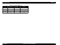
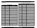
1
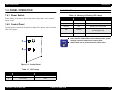
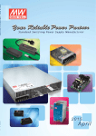
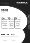
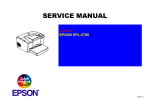
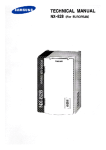
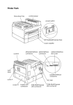
Download Service Manual And Resetter Printer at http://printer1.blogspot.com
Monochrome Page Printer
EPSON EPL-5700L/5700i
®
SEPG99007
Download Service Manual And Resetter Printer at http://printer1.blogspot.com
Notice:
All rights reserved. No part of this manual may be reproduced, stored in a retrieval system, or transmitted in any form or by any means,
electronic, mechanical, photocopying, recording, or otherwise, without the prior written permission of SEIKO EPSON CORPORATION.
The contents of this manual are subject to change without notice.
All efforts have been made to ensure the accuracy of the contents of this manual. However, should any errors be detected, SEIKO EPSON
would greatly appreciate being informed of them.
The above not withstanding SEIKO EPSON CORPORATION can assume no responsibility for any errors in this manual or the consequences
thereof.
EPSON is a registered trademark of SEIKO EPSON CORPORATION.
General Notice:
Other product names used herein are for identification purpose only and may be trademarks or registered trademarks of their
respective owners. EPSON disclaims any and all rights in those marks.
Copyright © 1999 SEIKO EPSON CORPORATION. Printed in Japan.
Download Service Manual And Resetter Printer at http://printer1.blogspot.com
PRECAUTIONS
Precautionary notations throughout the text are categorized relative to 1) Personal injury and 2) Damage to equipment.
DANGER
Signals a precaution which, if ignored, could result in serious or fatal personal injury. Great caution should be exercised in
performing procedures preceded by DANGER Headings.
WARNING
Signals a precaution which, if ignored, could result in damage to equipment.
The precautionary measures itemized below should always be observed when performing repair/maintenance procedures.
DANGER
1. ALWAYS DISCONNECT THE PRODUCT FROM THE POWER SOURCE AND PERIPHERAL DEVICES WHEN PERFORMING ANY
MAINTENANCE OR REPAIR PROCEDURES.
2. NO WORK SHOULD BE PERFORMED ON THE UNIT BY PERSONS UNFAMILIAR WITH BASIC SAFETY MEASURES AS DICTATED FOR
ALL ELECTRONICS TECHNICIANS IN THEIR LINE OF WORK.
3. WHEN PERFORMING TESTING AS DICTATED WITHIN THIS MANUAL, DO NOT CONNECT THE UNIT TO A POWER SOURCE UNTIL
INSTRUCTED TO DO SO. WHEN THE POWER SUPPLY CABLE MUST BE CONNECTED, USE EXTREME CAUTION IN WORKING ON
POWER SUPPLY AND OTHER ELECTRONIC COMPONENTS.
WARNING
1. REPAIRS ON EPSON PRODUCT SHOULD BE PERFORMED ONLY BY AN EPSON CERTIFIED REPAIR TECHNICIAN.
2. MAKE CERTAIN THAT THE SOURCE VOLTAGES IS THE SAME AS THE RATED VOLTAGE, LISTED ON THE SERIAL NUMBER/RATING
PLATE. IF THE EPSON PRODUCT HAS A PRIMARY AC RATING DIFFERENT FROM AVAILABLE POWER SOURCE, DO NOT CONNECT IT
TO THE POWER SOURCE.
3. ALWAYS VERIFY THAT THE EPSON PRODUCT HAS BEEN DISCONNECTED FROM THE POWER SOURCE BEFORE REMOVING OR
REPLACING PRINTED CIRCUIT BOARDS AND/OR INDIVIDUAL CHIPS.
4. IN ORDER TO PROTECT SENSITIVE MICROPROCESSORS AND CIRCUITRY, USE STATIC DISCHARGE EQUIPMENT, SUCH AS ANTISTATIC WRIST STRAPS, WHEN ACCESSING INTERNAL COMPONENTS.
5. REPLACE MALFUNCTIONING COMPONENTS ONLY WITH THOSE COMPONENTS BY THE MANUFACTURE; INTRODUCTION OF
SECOND-SOURCE ICs OR OTHER NONAPPROVED COMPONENTS MAY DAMAGE THE PRODUCT AND VOID ANY APPLICABLE EPSON
WARRANTY.
Download Service Manual And Resetter Printer at http://printer1.blogspot.com
PREFACE
This manual describes basic functions, theory of electrical and mechanical operations, maintenance and repair procedures of EPL-5700L/5700i. The
instructions and procedures included herein are intended for the experienced repair technicians, and attention should be given to the precautions on
the preceding page. The chapters are organized as follows:
CHAPTER 1.
PRODUCT DESCRIPTIONS
Provides a general overview and specifications of the product.
CHAPTER 2.
OPERATING PRINCIPLES
Describes the theory of electrical and mechanical operations of the product.
CHAPTER 3.
TROUBLESHOOTING
Provides the step-by-step procedures for troubleshooting.
CHAPTER 4.
DISASSEMBLY AND ASSEMBLY
Describes the step-by-step procedures for disassembling and assembling the
product.
CHAPTER 5.
ADJUSTMENTS
Provides Epson-approved methods for adjustment.
CHAPTER 6.
MAINTENANCE
Provides preventive maintenance procedures and the lists of Epson-approved
lubricants and adhesives required for servicing the product.
CHAPTER 7.
APPENDIX
Provides the following additional information for reference:
• Connector Pin Assignments
• Circuit Board Component Layout
• Exploded Diagrams and ASP List
• Circuit Diagram
Download Service Manual And Resetter Printer at http://printer1.blogspot.com
Revision Status
Revision
Issued Date
Description
A
September 2, 1999
First Release
EPL-5700L/5700i
Revision A
Table of Contents
PRODUCT DESCRIPTION
DISASSEMBLY AND ASSEMBLY
FEATURES ................................................................................................... 8
OVERVIEW ................................................................................................. 30
BASIC SPECIFICATIONS .......................................................................... 10
DISASSEMBLY AND ASSEMBLY ............................................................. 31
Control Panel Removal .......................................................................... 31
Top Cover Removal ............................................................................... 31
Main Control Board Removal ................................................................. 33
PAPER SPECIFICATIONS ......................................................................... 15
PANEL OPERATION .................................................................................. 17
Power Switch .......................................................................................... 17
Control Panel .......................................................................................... 17
RAM EXPANSION ...................................................................................... 18
ADJUSTMENTS
OPTIONS AND CONSUMABLE PRODUCTS ............................................ 19
OPERATING PRINCIPLES
OPERATING PRINCIPLES OF MECHANISM ........................................... 21
ELECTRIC CIRCUIT ................................................................................... 22
Operating Principles of Controller .......................................................... 22
MAINTENANCE
APPENDIX
CONNECTOR PIN ASSIGNMENTS ........................................................... 39
CIRCUIT BOARD COMPONENT LAYOUT ............................................... 41
TROUBLESHOOTING
OVERVIEW ................................................................................................. 26
Overview ................................................................................................ 26
Electric Check Point ............................................................................... 26
EXPLODED DIAGRAMS & ASP LIST ....................................................... 42
Exploded Diagrams ................................................................................ 42
ASP List ................................................................................................. 50
CIRCUIT DIAGRAM .................................................................................... 54
HANDLING SERVICE CALL ERRORS ...................................................... 27
Service Call Error Conditions ................................................................. 27
Error LED Lamp ..................................................................................... 27
Error Code Display and Remedies ......................................................... 27
6
Download Service Manual And Resetter Printer at http://printer1.blogspot.com
PRODUCT DESCRIPTION
EPL-5700L/5700i
Revision A
1.1 FEATURES
T he follow ing sho w s fea tures of E P L-5 700 L/57 00i.
ENGINE
600 dpi reso lution, 8 pp m printin g sp eed
S tand ard p ape r feed ing is b y a casse tte-like universa l pa per tra y (1 50
she ets) and a m a nua l fe ed tra y (1 she et).
O p tion al p ape r feed ing is b y a A 4 or L T lo w e r pape r fee der un it (5 00
she ets).
Speed is enhanced by compressed data expansion hardware.
T he follow ing functio ns can be u pgrad ed a nd spee d can b e in creased
by R A M S IM M expansion .
C o m pa ct, ligh tw eigh t A 4 e ngin e
The compressed data is expanded in real-time by the expansion
circuit and transferred to the engine.
Enhanced MicroGray printing
Receive buffer capacity
Printing speed
RESTRICTIONS / DIFFERENCES WITH EPL-5700
1. A network I/F, including external attachment cannot be used.
CONTROLLER
2. Fonts are not installed.
A new ly de veloped host-ba sed con troller
3. The emulation is not installed.
4. Only the Windows 95/98, Windows NT 4.0 and Macintosh operating
systems (8.1 or later) are supported.
CPU: TMP95C001, TOSHIBA
EDO RAM or FastPage RAM (60 ns)
5. The ROP and fill methods change, so there may be differences in
the output.
Inte rface
ECP compatible parallel I/F which conforms to IEEE 1284
6. When using halftones, the printed image may be different.
USB interface
7. There are differences with operation when “Toner out” occurs.
M ou nted w ith R IT e ch, E nhan ced M icroG ray
8. The driver UI is different.
A n un derline e rror m a y occu r w h en p rinting a com plicated im age w ith
600 dpi E nha nce d M icroG ray printing.
M ou nted w ith T o ner S a ve M ode
10. With the standard memory, printing at 600 dpi with MicroGray ON
may not be possible. Also, for a host that is not capable of ECP
communication, printing may not be possible with standard memory.
M ou nted w ith b i-dire ctional I/F (IE E E 12 84)
A host -based printer is possible.
11. The printer status can be displayed on the screen and printing is
possible upon user’s request.
D a ta com p ression technology
9. It can only be connected to a Macintosh with a standard USB
connection. Optional USB board is not guaranteed.
By sending compressed data from the host, printing with a 2MB
memory is possible.
PRODUCT DESCRIPTION
FEATURES
8
EPL-5700L/5700i
Revision A
12. The recommended host environments are:
W ind ow s:
P entium 2 33 M H z an d 64 M B R A M o r m ore
M acintosh :
G 3 233 M H z a nd 6 4 M B R A M or m o re
13. For Windows NT 4.0, EPSON Printer Port Monitor must be installed
to use ECP.
14. Even if the option RAM is expanded by 16 MB or more, only a
maximum of 13 MB is valid.
15. When using parallel connection, printing is not possible if bidirectional communication is hindered by the following conditions.
There is a printer selecting switch between the PC and the
printer for parallel connection.
Old PC that does not support bi-directional communication is
used.
Unspecified cables are used.
16. If there is no paper in the MP tray, the paper size will become
unclear.
17. Status sheet printing cannot be performed by the printer itself.
18. The printer cannot be shared in a Macintosh network.
PRODUCT DESCRIPTION
FEATURES
9
EPL-5700L/5700i
Revision A
1.2 BASIC SPECIFICATIONS
W arm -u p T im e:
The EPL-5700L/5700i is a compact host-based A4 monochrome page
printer that is driven by laser and digital photographic technology. The
following shows basic specifications.
PRINTABLE AREA
P rint A re a:
20 second s o r less (at 23 °C , stand ard volta ge)
A rea w ithin m argins of 4m m fro m ea ch sid e (S ee
F ig ure 1-1 below )
PROCESS
D ry M o no-com po nen t E lectrop hoto graph ic M eth od
Lig ht S ou rce:
S em icon ductor La ser
P hoto ele ctric U nit:
O P C D rum (O rga nic P hoto con ductor)
C h arge :
R otating B ru sh C ha rging T yp e
D e velope r:
E xpo sed S ection D e velope r S ystem
T one r
M on o-co m po nent N o nm a gne tic T oner
T ransfer M etho d:
R olle r T ransfer
F ixing:
H eat R oller S yste m
D e nsity R eg ula tor:
D eve lope r B ias V aria tion S ystem (can b e
regu late d by user)
R e solutio n:
600 dpi
4mm
4mm
4mm
P rint M eth od:
4mm
Printable Area
PRINTING SPEED
P rinting S p eed:
8 p pm (A 4/B 5/A 5 V e rtica l F ee d)
F irst P rint:
19 second s (A 4 V e rtica l F ee d)
Figure 1-1. Printable Area
18.2 se con ds (B 5 )
17.3 se con ds (A 5 )
PRODUCT DESCRIPTION
BASIC SPECIFICATIONS
10
EPL-5700L/5700i
Revision A
PAPER HANDLING
P ape r S upply:
CONSUMABLES
150 -she et C assette-like M ultipurpo se T ray
N am e :
M an ual F eed S lot
O p tion al C assette:
P hotoco nductor U nit
500 -she et A 4 Low er C assette U nit
Life:
Multipurpose Tray
Capacity
Paper Size
Permissible
Paper Thickness
150 sheets
76.2 x 127 to
215.9 x 355.6mm
60 to 90g/m2
(16 to 24lb)
50 sheets
Japanese Official
Postcard
20 sheets
Japanese Official
Postcard (when
printing on back)
10 sheets
Manual Feed Slot
Lower Cassette
P ape r O utput:
1 sheet
500 sheets
Envelope/Label
OHP/Thick Page
100 x 148 to
215.9 x 355.6mm
A4
CONTROLLER SPECIFICATIONS
CPU:
190g/m2
16 bit, 64pin, m ax 2 5M H z, C IS C ,
T M P 9 5C 001 (T O S H IB A )
RAM:
Normal Paper:
60 to 90g/m2
Thick Paper:
90 to 190g/m2
Special Paper
Normal Paper:
60 to 90g/m2
Thick Paper:
90 to 190g/m2
Special Paper
A ve rage of 20 ,000 sh eets
(at continuo us printing on A 4 page w ith p rint duty
of 5% )
S tan dard: 2M B (E D O )
O p tio nal S IM M S lot: 1
32 M B , 16 M B , 8 M B , 4M B (E D O )
(A m a xim um o f 13 M B is va lid.)
ROM:
P rogra m : 51 2K bytes
H ost Interface :
S tan dard: C e ntron ics, B i-directiona l P arallel
IE E E -128 4 nibble
Normal Paper:
60 to 90g/m2
E C P com pliant
USB:
F ace-dow n
F ace-up (w he n an optiona l ho ppe r is use d)
PRODUCT DESCRIPTION
E T C artrid ge: A ve rage of 3,000 she ets
O P C D rum :
Table 1-1. Paper Handling
Paper Supply
E T C artrid ge
BASIC SPECIFICATIONS
S eria l
(N o slot fo r the optiona l I/F )
11
EPL-5700L/5700i
Revision A
A C Lin e N oise:
P ulse W idth:
50 to 1 ,000 ns
T his prin ter is ho st-ba sed , na m ely, th e ho st com p uter (p rinte r driver)
gen erate s print im age s. R efer to the softw are guide fo r details.
P ulse P o larity:
±
R epe at:
N on-sim u ltan eous
ENVIRONMENTAL CONDITIONS
M o de:
C om m on/N orm al
T em p eratu re (in clu ding expend able pa rts):
V oltage:
1K V
SOFTWARE SPECIFICATIONS
O p eration:
10 to 3 5 °C
S torag e un der n orm al co nditions:
P arts can w ithstan d up to 2 K V w ithou t dam age .
0 to 3 5 °C
Instant C u toff:
S torag e un der e xtrem e condition s: -20 to 40 °C
(1/30 of the to tal hold ing period)
E lectrostatic D urab ility: N o ha rdw are erro rs up to ± 1 0K V .
H u m id ity (including e xpe nda ble parts):
O p eration:
(N o un re coverab le softw are errors)
15 to 85 % w itho ut cond ensatio n
C om p onen ts can w ithstand up to ± 15K V w ith out
da m age .
S torag e un der n orm al co nditions: 30 to 85 %
S torag e un der e xtrem e condition s: 10 to 95 %
(1/30 of the to tal hold ing period)
ELECTRICAL SPECIFICATIONS
P ow er S up ply V olta ge:
100 ± 10%
P ow er S up ply F requ ency:
50 to 60 H z ± 3H z
S tand ard M axim um C urrent:
6.3 A
P ow er C onsum p tion :
D IP 100 % (for stan dard voltage - 10% ) for on e
cycle w ith n orm a l print qu ality.
M axim u m :
R ush C u rrent:
1/2 cycle , 50 A or le ss
Insula tion R e sistan ce:
10 M
D iele ctric S tren gth:
A C 1000 V is app lied for o ne m inu te w ith no
brea kdo w n s (du ratio n of one surg e).
Lea kag e C urren t:
0.2 5m A o r less (10 0V m o del)
Ω
o r hig her
580 W
A vera ge d uring co ntin uous printin g:20 0W
S tand by M od e (H eate r O n ):
490 W
S tand by M od e (H eate r O ff):
15 W
PRODUCT DESCRIPTION
BASIC SPECIFICATIONS
12
EPL-5700L/5700i
Revision A
DIMENSIONS
D im en sio ns:
M ain U nit: 397 m m (W ) x 49 3m m (L) x 251 m m (H )
W eig ht:
A ppro x. 7 .5kg
RELIABILITY AND DURABILITY
P roduct Life:
A ppro x. 1 80,0 00 p rinted pag es or five years,
w hichever co m es first
M PBF:
25,000 she ets or m o re
M TBF:
3,0 00 h ours (10 m onth s) or m ore
P ape r F eed R e lia bility
(w h en u sin g th e recom m end ed p aper u nde r
norm al cond itio ns)
Jam R ate:
1/2 000 or less (n ot including m ultiple p age s)
M isfee d:
1/2 000 or less
M ultiple P ag e F ee d R ate : 1/5 00 o r less
P ape r W rinkling :
1/1 000 or less
P ape r Lea ding E dge F old s:1 /100 0 or less
(corn er folds m ore than 1m m )
PRODUCT DESCRIPTION
BASIC SPECIFICATIONS
13
EPL-5700L/5700i
Revision A
APPLICABLE CERTIFICATION STANDARDS AND REGURATIONS
[EMC]
Table 1-4. EMC
T he spe cifications of this eng ine m ee t the ce rtificatio n stand ards and
regu lations ind ica ted b elo w . T here are case s in w hich th e stand ards and
regu lations a pply differen tly to prod ucts, includ ing the contro ller, d epe ndin g
on their destina tion .
Model Name
100V Model
CNS 13438
CISPR22 (Taiwan)
FCC Part15 Subpart B Class B/CSA C108.8 Class B
200V Model
EC EMC Directive 89/336/PEC
EN55022 Class B
EN61000-3-2
EN61000-3-3
EN50082-1
AS 3548 (Australia)
[Safety Standards]
Table 1-2. Safety Standards
Model Name
Applicable Certification
120V Model
UL 1950
CSA 22.2 No.950
200V Model
TÜV-GS (EN60950)
NEMKO (EN60950)
P ow er C onsum ptio n:
In com plia nce w ith intern atio nal E nergy S tar
sta nda rds.
[Safety Regulations]
Table 1-3. Safety Regulations
Model Name
Applicable Certification
120V Model
FDA (NCDRH) Class 1
200V Model
TÜV-GS (EN60825)
NEMKO (EN60825)
O thers:
T on er:
D oes not affe ct h um an bod y (in accord ance w ith
O S H A , T S C A , E IN E C S and C S C L).
OPC:
D oes not affe ct h um an bod y (in accord ance w ith
O S H A ).
O zone E m issions:
C onfo rm s to U L 47 8, 5 th version.
M a terials:
C onfo rm s to S w iss en viron m en tal protectio n la w s
(doe s n ot in clu de C dS ).
PRODUCT DESCRIPTION
Applicable Certification
O zone :
0.0 2 pp m or less
P ote ntia l T oxicity:
O P C , toner, and pla stic pa rts are non toxic.
N oise:
S tan d-by:
30 dB (A ) or less
In opera tion :
47 .0 dB (A ) o r less
BASIC SPECIFICATIONS
14
EPL-5700L/5700i
Revision A
1.3 PAPER SPECIFICATIONS
PAPER CLASSIFICATIONS
Table 1-5. Paper Classification
T he typ es of pap er w hich can be used w ith E P L -5700 L/57 00i are de scribed
below .
Special Paper
Paper
Supply
PAPER TYPES
N o rm al P ape r:
P P C , recycle d pa per 6 0 to 90g /m 2 (16 to 24 lbs)
S pecial P aper:
Lab els, Ja pan ese officia l po stcards, O H P film s,
co lor pa per, thick p aper (9 0 to 157 g/m 2 ), special
D T P , and letterhea d
Paper Tray
Lower
Cassette
Normal
Paper
OHP
Japanese
Official
Postcard
Label
Thick
Paper
Envelope
X
X
X
X
X
: Can guarantee paper feed reliability and image quality. However, this is limited to
generally used paper.
C A U T IO N
•
•
•
•
•
•
•
•
•
•
•
•
The paper types listed below cannot be used with this
printer.
Carbon paper, non-carbon paper, thermal transfer paper, impact
paper, and acidic paper.
Paper which has been used with a thermal transfer or ink-jet
printer.
Paper which is too thick or too thin.
Wet (damp) paper.
Paper to which a special coating has been applied, or colored
paper which has gone through surface processing.
Paper whose surface is too smooth or too rough, or paper
whose texture is different on the front and back.
Paper with holes for binders or perforations.
Folded, curled, or damaged paper.
Paper of irregular shape or not cut with right angles.
Paper with labels that come off easily.
Paper with glue, staples, or paper clips attached.
Special ink-jet paper.
When using illustrated postcards, paper particles may
adhere to the paper feed roller and cause paper feed
difficulty. Therefore, it will be necessary for users to
perform cleaning as indicated in Chapter 6 “Maintenance”.
PRODUCT DESCRIPTION
: Can print characters. However, this is limited to generally used paper.
X: Cannot feed.
PAPER SPECIFICATIONS
15
EPL-5700L/5700i
Revision A
PAPER SIZE
Table 1-6. Paper Size
Paper
Type
Paper
Size
mm (inch)
A4
210 x 297
A5
148 x 210
JIS-B5
182 x 257
Letter
(8.5) x (11)
Half Letter
(5.5) x (8.5)
Legal
(8.5) x (14)
EXE
(7.25) x (10.5)
Government
Legal
(8.5) x (13)
Government
Letter
(8) x (10.5)
F4
210 x 330
Postcard
100 x 148
Monarch
98.43 x 190.5
C10
104.78 x 241.3
DL
110 x 220
C5
162 x 229
C6
114 x 162
InternationalB5
176 x 250
Normal
Paper
Special
Paper
Paper
Tray
Manual
Feed Slot
Optional
Lower
Cassette
-
: A p plicable
PRODUCT DESCRIPTION
PAPER SPECIFICATIONS
16
EPL-5700L/5700i
Revision A
1.4 PANEL OPERATION
FLASHING LED
1.4.1 Power Switch
Table 1-8. Meaning of Flashing LED Lamps
P ow er S w itch is locate d on the left re ar side of th e printer, a nd it co ntrols
pow er o n/off.
1.4.2 Control Panel
C o ntrol P a nel is located a t the righ t front ed ge of th e printer, and it consists
of tw o LE D lam ps.
Ready Lamps
Error Lamp
Meaning
OFF
OFF
Power OFF.
ON
OFF
Possible to print.
Flashing
OFF
Warming up, receiving data
OFF
Flashing
Recoverable error
(including paper out)
OFF
ON
Service call error
C H E C K
P O IN T
1
Since the EPL-5700L/5700i is a host-based printer, printer
settings cannot be made on the control panel.
Status sheet can be printed from the printer driver.
2
Figure 1-2. Control Panel
Table 1-7. LED Lamps
Name
Color
1
Ready Lamp
Green
2
Error Lamp
Red
PRODUCT DESCRIPTION
PANEL OPERATION
17
EPL-5700L/5700i
Revision A
1.5 RAM EXPANSION
If m em ory sh ortag e occurs, th e prin ter o utpu ts a m isprin t and an error
m essa ge a ppea rs on the host screen . In such a case, it is necessary to
install expansion m e m ory R A M (R A M S IM M ).
T he reco m m e nded R A M capacity for con ditions of u se are a s show n below .
(H o w e ver, this doe s n ot in clu de im ag es w ith extrem ely poo r com pressio n
ratio .)
Table 1-9. Recommended RAM Capacity
No RAM Expansion
• MicroGray printing may not be possible at 600 dpi.
• For a host with slow transfer speed, normal 600
dpi printing may not be possible.
4MB Expansion
Printing is possible under all conditions
C A U T IO N
The memory shown below cannot be used with the EPL5700L/5700i. The CPU of the printer is 16bit, but the
following memory is not designed to allow access at 16bit.
SAMSUNG KMM5328104
PRODUCT DESCRIPTION
RAM EXPANSION
18
EPL-5700L/5700i
Revision A
1.6 OPTIONS AND CONSUMABLE PRODUCTS
O p tion al lo w e r cassette unit a nd printer ca ble s for E P L-57 00L /570 0i are th e
sam e a s op tion s fo r E P L-570 0.
PRODUCT DESCRIPTION
OPTIONS AND CONSUMABLE PRODUCTS
19
Download Service Manual And Resetter Printer at http://printer1.blogspot.com
OPERATING PRINCIPLES
EPL-5700L/5700i
Revision A
2.1 OPERATING PRINCIPLES OF MECHANISM
T he E P L-5 700L /570 0i ad opts the sam e m ech anism a s use d in th e previou s
m od el. R e fer to the E P L -5700 S ervice M anu al for the detaile d op erating
prin cip les of e ach m echan ism .
OPERATING PRINCIPLES
OPERATING PRINCIPLES OF MECHANISM
21
EPL-5700L/5700i
Revision A
2.2 ELECTRIC CIRCUIT
T he M ain C ontroller p roce sse s p rint d ata sen t from the host co m puter an d
gen erates video sig nal.
S ince the E lectric C ircuit of this printer is basically the sa m e a s th at of E P L5700 , this section exp lain s o nly abo ut th e M a in C on trol B o ard a nd its
re late d pa rts.
T he E n gin e C ontro ller re ceives video sig nal from the M ain C ontroller a nd
drives the e ngin e to prin t.
2.2.1 Operating Principles of Controller
FUNCTIONS OF THE MAIN CONTROLLER
T he C 29 2 M a in B o ard, w hich function s a s a con trolle r of the p rinte r,
con sists o f the M ain C ontrolle r and the E ngin e C ontro lle r.
Main Controller
TUSB
USB I/F
C o m m u nicatio n w ith the host co m puter (receiving print data and
sen din g status).
P roce ssing the p rint d ata (a nalyzing com m and and gen erating vide o
sig nal).
S ending the vide o signa l to the E n gin e C ontro lle r.
M on itoring p anel or sw itch con ditions.
FUNCTIONS OF THE ENGINE CONTROLLER
DRAM
RAMSIMM (CN1)
CPU
Parallel I/F
SLC
JP1
1284DRIVER
R e ceivin g th e video sig nal and sen din g en gine sta tus.
M on itoring sensors.
C o ntrolling the optiona l lo w e r casse tte.
B lock diagra m of the C 29 2 M ain B o ard a nd function of e ach device are
sho w n on the follo w ing p age .
ROM
Video (CN3)
CPU
Engine Controller
Figure 2-1. C292 Main Board
OPERATING PRINCIPLES
ELECTRIC CIRCUIT
22
23
Revision A
CPU
TM95C001
64pin
(IC1)
+22.9982MHz
-22.9982MHz
MCLKOX
ROM
4Mb*16
40pin
(IC2)
22.9982MHz
MCLKIN
16
DRAM
16Mb*16
42pin
(IC3)
MA10-0
Reset Signal
16
CN5
RAMSIMM
72pin
USB
4pin
D15-0
16
SLC
208pin
(5/3.3V)
E05B68NA
16
TSUB
64pin
(5/3.3V)
E05B69NA
(IC21)
(IC5)
3.3V 5V
CN207
CN1
Reg.
PQ3DZ13
Serial
EEPROM
1kb
(IC8)
ELECTRIC CIRCUIT
Reset IC
(IC6)
Figure 2-2. Block Diagram of the C292 Main Board
A23-1
3.3V
LV161284
48pin
(IC7)
Parallel
36pin
EPL-5700L/5700i
Engine
Controller
CN3
OPERATING PRINCIPLES
CN2
48MHz
EPL-5700L/5700i
Revision A
Table 2-1. C292 Main Board - Main Controller (continued)
Table 2-1. C292 Main Board - Main Controller
Name
CPU
TM95C001
Location
IC1
Name
Functions
16bit CISC-CPU driven at clock frequency
25MHz.
Package: 64pin, QFP
Power supply voltage: 5V Single
IC5
This ASIC controls the following:
• Memory (RAM/ROM)
• DMA (Video, I/O)
• RIT (Resolution Improvement Tech.) / PGI
(Photo Grade Improvement) function.
• Video I/F (communication with the Engine
Controller)
• Panel LED
Package: 208 pin, QFP
Power supply voltage: 5V/3.3V
Operation frequency: DMAC max 25MHz
PIF max 25MHz
DCMP max 60MHz
RIT max 100MHz
ASIC (TUSB)
E05B69NA
IC21
Controls USB I/F.
Package: 64 pin, QFP
Power supply voltage: 5V/3.3V
Operation frequency: max 48MHz
TTL
SN74LV162184DGGR
IC7
1284 driver. Receives / sends parallel I/F
signal.
Power supply voltage: 5V
DRAM
M5M418165CJ-6
IC3
One EDO with 16Mb, 16bit, 60ns is mounted.
Operates as standard memory.
ROM
HN27C4000G-10
IC2
4Mb, 16bit, and 40pin module. Stores the
control program.
RAMSIMM
CN1
72 pin, memory expansion connector
ASIC (SCL)
E05B68NB
OPERATING PRINCIPLES
Location
Functions
USB I/F
CH5
USB connector with the host PC
Parallel I/F
CH2
Parallel connector with the host PC
Control Panel I/F
CN4
LED-control connector
Table 2-2. C292 Main Board - Engine Controller
Name
Location
Functions
CPU
M38073E4FS
IC201
Controls the engine.
Motor Drive IC
TEA3718SDP
IC204/
IC205
Drives the main motor.
ELECTRIC CIRCUIT
24
Download Service Manual And Resetter Printer at http://printer1.blogspot.com
TROUBLESHOOTING
EPL-5700L/5700i
Revision A
3.1 OVERVIEW
3.1.1 Overview
S ince th e E P L-57 00L /570 0i is a host-based p rinte r, m ost pro blem s can be
solved by ope ratin g “E P S O N P rin ter W in dow !3” on th e ho st com p ute r.
W hen an e rror occurs, “E P S O N P rin ter W in dow !3 ” appe ars on th e ho st
screen a s a pop-u p w ind ow , w h ich provide s de tailed in stru ctio ns o n ho w to
han dle each error. M ost of the errors w ill be cleared by follow ing the
instruction s of the pop-u p w ind ow .
A lso refer to th e se ction “T rou ble sho otin g” of the E P L -5700 L/57 00i U ser’s
G u ide, w h ich gives instruction s fo r solvin g ge neral prob lem s.
3.1.2 Electric Check Point
R e fer to 3.2 of th e E P L-5 700 S e rvice M anua l.
TROUBLESHOOTING
OVERVIEW
26
EPL-5700L/5700i
Revision A
3.2 HANDLING SERVICE CALL ERRORS
T his section describ es va rious cond itio ns w h ich m a y cau se fata l e rro rs, and
provide s rem edies for su ch e rrors.
Table 3-1. Service Call Error Codes
Service Call Error Code
Protocol Error
Replace the Main Board.
C1999
Video Error
Replace the Main Board.
C1999
Data Expansion Error
Replace the Main Board.
C1000
Standard RAM Check
Error
Replace the Main Board.
C1200
EEPROM Access
Error
• Initialize EEPROM.
• Replace the Main
Board.
Software Error
• Reboot the host PC.
• Reinstall the driver.
• Replace the Main
Board.
Abnormal Fusing
Refer to 3.4.2.3 of the
EPL-5700 Service
Manual.
E0006
Abnormal Polygon
Motor
Refer to 3.4.2.2 of the
EPL-5700 Service
Manual.
E0009
Abnormal Laser
Refer to 3.4.2.1 of the
EPL-5700 Service
Manual.
E0014
Communication Error
with Engine
• Replace the engine.
• Replace the Main
Board.
N o te th at th e fo llo w in g o perations w ill re sult in the S ervice C all E rrors
w ithou t fail.
B ringing u p th e B IO S se tting s scree n w ith the p rinte r pow er o n.
T urning o n - off - on the printe r w h ile prin ting .
T urning o n “A pple T a lk” w hile u sin g E P S O N L IN K 3 .
U sing the prin ter driver o ther than designa ted for th e E P L-57 00L/5700 i.
C2000
3.2.2 Error LED Lamp
R e ady Lam p:
OFF
E rror Lam p:
O N (R ed)
Win
Mac
E0003
E2000
3.2.3 Error Code Display and Remedies
In m ost S ervice C all E rror case s, the p rinter re covers from the e rror if it is
turne d off and on again. H ow ever, in the ca se w he re the prin ter do es not
reco ver from th e erro r eve n after the abo ve ope ra tion , ch eck the S ervice
C a ll E rro r C o de a nd ta ke appro priate m e asu res a s show n in T a ble 3-1.
SERVICE CALL ERROR CODE DISPLAY
If a S ervice C all E rror occu rs an d “E P S O N P rin ter W in dow !3” pops up
on the screen , p ress C trl+ S hift+E n ter toge ther to display the error code .
C A U T IO N
Remedy
I0001
3.2.1 Service Call Error Conditions
Error Description
This function should not be made open to users.
TROUBLESHOOTING
HANDLING SERVICE CALL ERRORS
27
EPL-5700L/5700i
Revision A
RESETTING EEPROM
1. Open the printer’s “Properties” (or “Document Defaults” for Windows
NT4.0), and select “Optional Settings”.
2. Click the left button of the mouse while pressing
ALT+CTRL+SHIFT+W, and the dialogue box shown below will
appear.
Cancel
Figure 3-1. Reset the EEPROM
3. Click “OK”, and EEPROM will be reset.
C A U T IO N
The above function should not be made open to users.
TROUBLESHOOTING
HANDLING SERVICE CALL ERRORS
28
Download Service Manual And Resetter Printer at http://printer1.blogspot.com
DISASSEMBLY AND ASSEMBLY
EPL-5700L/5700i
Revision A
4.1 OVERVIEW
T he follow ing parts and units o f the E P L-570 0L/5 700 i are different from
those o f E P L-57 00.
C o ntrol P ane l
T op cover se curing m etho d
M ain B oa rd
U S B I/F
T he othe r m echan ism and exterior p arts are e xactly the sam e as used in
E P L-570 0. T h erefo re , th is chap ter conta ins the disassem b ly and assem b ly
procedu re s o nly for th e pa rts a nd u nits m e ntio ned above. R efer to the E P L 570 0 S ervice M an ual for other item s.
DISASSEMBLY AND ASSEMBLY
OVERVIEW
30
EPL-5700L/5700i
Revision A
4.2 DISASSEMBLY AND ASSEMBLY
Hooks
4.2.1 Control Panel Removal
U n like th e pre vio us m ode l, th e E P L-57 00L /570 0i h as o nly tw o LE D lam ps
and no o the r function s o n the co ntrol pan el. H ow ever, e xterior of the p ane l
is exa ctly the sa m e a s th e pre vio us m ode l, a nd so is the w ay the p anel is
fixed o n the prin ter. R efe r to the E P L-5 700 S ervice M anu al (p p. 4 - 10) fo r
the C o ntrol P anel disassem bly and assem bly procedu re s.
Control Panel
Front Cover
Harness to Main Board
Figure 4-2. Control Panel Removal (No. 2)
4.2.2 Top Cover Removal
1. Remove the right cover (See section 4.2.2 of the EPL-5700 Service
Manual).
2. Remove the control panel (See section 4.2.1 of this manual).
3. Remove the front cover (See section 4.2.7 of the EPL-5700 Service
Manual).
4. Remove the left cover (See section 4.2.10 of the EPL-5700 Service
Manual).
Fixing Screws (CS M3X8)
Figure 4-1. Control Panel Removal (No. 1)
DISASSEMBLY AND ASSEMBLY
DISASSEMBLY AND ASSEMBLY
31
EPL-5700L/5700i
Revision A
5. Remove a screw (CS M3x8) and a plate located on the upper part of
the shield cover of the Main Control Board (see Figure 4-3 below).
6. Push both left and right hinges of the top cover outward as shown in
Figure 4-4, and remove the top cover.
Hinges
Top Cover
Plate
Screw (CS M3X8)
Figure 4-3. Plate Removal
Figure 4-4. Top Cover Removal
DISASSEMBLY AND ASSEMBLY
DISASSEMBLY AND ASSEMBLY
32
EPL-5700L/5700i
Revision A
4.2.3 Main Control Board Removal
1. Remove the right cover (See section 4.2.2 of the EPL-5700 Service
Manual).
2. Remove the control panel (See section 4.2.1 of this manual).
7. Remove a fixing screw for USB interface (CS M3x6) and two fixing
screws for parallel interface (CP M3x6), and remove the board.
Main Board Fixing Screws
USB Connector Fixing Screw
3. Remove the front cover (See section 4.2.7 of the EPL-5700 Service
Manual).
4. Remove 10 screws (CS M3x8) securing the shield cover of the Main
Control Board, and remove the shield cover (See section 4.2.9 of
the EPL-5700 Service Manual).
5. Remove the harnesses which are connected to the connector on the
Main Control Board.
6. Remove 10 screws (CS M3x8) securing the Main Control Board on
the printer (See section 4.2.9 of the EPL-5700 Service Manual).
Parallel
Connector
Fixing
Screws
Figure 4-5. Main Control Board Removal
DISASSEMBLY AND ASSEMBLY
DISASSEMBLY AND ASSEMBLY
33
Download Service Manual And Resetter Printer at http://printer1.blogspot.com
ADJUSTMENTS
EPL-5700L/5700i
Revision A
R e fer to the E P L-570 0 S ervice M an ual, C hapter 5 for adjustm en t
procedu re s.
ADJUSTMENTS
35
Download Service Manual And Resetter Printer at http://printer1.blogspot.com
MAINTENANCE
EPL-5700L/5700i
Revision A
R e fer to the E P L-570 0 S ervice M an ual, C hapter 6 for m a inte nance
procedu re s.
MAINTENANCE
37
Download Service Manual And Resetter Printer at http://printer1.blogspot.com
APPENDIX
EPL-5700L/5700i
Revision A
7.1 CONNECTOR PIN ASSIGNMENTS
T he figure b elow sh ow s interco nnectio ns w ith th e M ain B oard , and th e table
on the right show s functio n of each co nne ctor.
Table 7-1. Connector List
Board
Connector
Function
Reference
CN1
For Expanded RAMSIMM, 72 pin
EPL-5700 Service
Manual, Table 7-5
and 7-7
CN2
Parallel Interface, 36 pin
EPL-5700 Service
Manual, Table 7-8
CN3
Video (not used)
-
CN4
Control Panel (LED Control)
-
CN5
USB Interface
C292 Main Board
CN202
Fusing
Thermister
CN203
Paper Feed
Solenoid
CN204
High
Voltage
Board
CN205
Print
Head
CN206
Main
Motor
CN208
Paper
Eject
Sensor
CN209
Polygon
Motor
CN210
Paper
Feed
Sensor
CN212
Paper
Empty
Sensor
CN3
RAM
SIMM
CN1
Parallel
I/F
CN2
USB I/F
Control
Panel
CN5
CN4
Power Board
Heater
Lamp
CN1
CN2
CN207
CN3
Interlock
Switch
Lower
Cassette
C292 MAIN
High Voltage
Board
Power
Board
Table 7-2
CN202
Fusing Thermister
-
CN203
Paper Feed Solenoid Control
-
CN204
High Voltage Board
-
CN205
Print Head Control
-
CN206
Main Motor Control
-
CN207
Power Board
-
CN208
Paper Eject Sensor
-
CN209
Polygon Motor Control
-
CN210
Paper Feed Sensor
-
CN211
Lower Cassette Control
-
CN212
Paper Empty Sensor
-
CN1
Main Control Board
-
CN1
Main Control Board
-
CN2
Fusing Heater Lamp Control
-
CN3
Interlock Switch Control
-
CN211
Figure 7-1. Interconnection with the Main Board
APPENDIX
CONNECTOR PIN ASSIGNMENTS
39
EPL-5700L/5700i
Revision A
Table 7-2. Connector CN5 Pin
No.
Signal Name
Direction
Function
1
POWER
-
Cable Power Supply
2
D-
Bi-directional
Data Signal
3
D+
Bi-directional
Data Signal
4
GND
-
Ground
APPENDIX
CONNECTOR PIN ASSIGNMENTS
40
EPL-5700L/5700i
Revision A
7.2 CIRCUIT BOARD COMPONENT LAYOUT
Figure 7-2. C292 Main Control Board Component Layout
APPENDIX
CIRCUIT BOARD COMPONENT LAYOUT
41
EPL-5700L/5700i
Revision A
7.3 EXPLODED DIAGRAMS & ASP LIST
7.3.1 Exploded Diagrams
R e fer to the E P L-570 0 S ervice M an ual 7.3 “E xplo ded D iagra m ” as the
exterior a nd m echanism of th e E P L-57 00L /570 0i a re ba sically th e sa m e.
T he only differen ce w ith the previou s m odel is “P LA T E ”, w hich ha s b een
new ly add ed to (6) F R A M E S I, and its exp lode d diagram s are sho w n on th e
follow ing pag es.
APPENDIX
EXPLODED DIAGRAMS & ASP LIST
42
APPENDIX
EPL-5700L/5700i
EXPLODED DIAGRAMS & ASP LIST
43
Revision A
APPENDIX
EPL-5700L/5700i
EXPLODED DIAGRAMS & ASP LIST
44
Revision A
APPENDIX
EPL-5700L/5700i
EXPLODED DIAGRAMS & ASP LIST
45
Revision A
APPENDIX
EPL-5700L/5700i
EXPLODED DIAGRAMS & ASP LIST
46
Revision A
APPENDIX
EPL-5700L/5700i
EXPLODED DIAGRAMS & ASP LIST
47
Revision A
APPENDIX
EPL-5700L/5700i
EXPLODED DIAGRAMS & ASP LIST
48
Revision A
APPENDIX
EPL-5700L/5700i
EXPLODED DIAGRAMS & ASP LIST
49
Revision A
EPL-5700L/5700i
Revision A
7.3.2 ASP List
Table 7-3. Parts List (continued)
Table 7-3. Parts List
Diagram No.
Parts Code
1-01
1040689
TOP COVER ASSY.
1-03
1048628
LEFT COVER
1-05
1048629
FRONT COVER
1-06
1040693
TRAY
1-07
1040697
CASSETTE BODY
1-08
1013911
GEAR 14T
1-09
1040698
TABLE
1-10
1040699
GUIDE
1-11
1040700
GUIDE
1-12
1040694
RIGHT COVER
1-13
1040701
COVER
1-14
1040695
COVER
1-15
1040696
TRAY ASSY.
1-16
1040702
SHEET
1-17
1050576
LOGO PLATE
450
2031327
PANEL
200
2032935
BOARD ASSY., MAIN
2-01
1040703
GUIDE
2-02
1048622
ROLLER
2-03
1048624
GUIDE LEVER
2-04
1040706
GEAR ASSY.
2-05
1040709
TORSION SPRING
2-06
1040710
COVER
APPENDIX
Parts Name
Diagram No.
Parts Code
2-07
1040711
ROCK LEVER
2-08
1040712
PLATE
3-01
1021636
BUSHING
3-02
1040714
CAM
3-03
1040715
ROLL
3-04
1048613
ROLLER
3-05
1040717
ROLLER
3-06
1040718
HOLDER
3-07
1040719
PRESSURE SPRING
3-08
1040720
JOINT
3-09
1048612
BUSHING
3-10
1040722
GEAR 18T
3-11
1048614
SHAFT
3-12
1040724
GEAR 36/54T
3-13
1040725
GEAR 36T
3-14
1040726
SHOULDER SCREW
3-15
2027738
SOLENOID
3-16
1040727
TORSION SPRING
3-17
1040728
PLATE
3-18
1040729
PLATE
3-19
1014684
PIN
3-20
1040730
LEVER
3-21
1040731
TORSION SPRING
3-22
1040732
ARM
3-23
1040733
SEPARATED PAD
EXPLODED DIAGRAMS & ASP LIST
Parts Name
50
EPL-5700L/5700i
Revision A
Table 7-3. Parts List (continued)
Diagram No.
Parts Code
3-24
1040734
3-25
Table 7-3. Parts List (continued)
Diagram No.
Parts Code
PRESSURE SPRING
4-28
1048616
HOLDER L
2027737
PAPER PICK UNIT
4-29
1048617
HOLDER R
4-01
1040801
HOLDER
4-30
1048618
STOPPER L
4-02
1040802
GEAR 36T
4-31
1048619
STOPPER R
4-03
1040803
BUSHING
4-32
1013954
SEPARATOR ROLL
4-04
1040804
FUSING ROLLER-FNT
5-01
1048630
FRAME
4-05
2028491
TUBE LAMP (H1 120V)
5-04
2027740
MOTOR (M1)
4-06
1040805
FUSING ROLLER-RR
5-05
1040738
GEAR 40T
4-07
1040806
BUSHING
5-06
1040739
GEAR 18/50T
4-08
1040807
PRESSURE SPRING
5-07
1040740
GEAR 20/44T
4-09
1040808
GUIDE
5-08
1040741
GEAR 20/52T
4-10
2027762
HARNESS
5-09
1040742
GEAR 24/30T
4-11
2027763
HARNESS
5-10
1040743
GEAR 20/48T
4-12
2027764
PHOTO INTERRUPTER (PS3)
5-11
1040744
GEAR 20/32T
4-13
2027765
ACTUATOR
5-12
1040745
GEAR 17/42T
4-14
1040809
BUSHING
5-13
1040746
GEAR 26T
4-15
1040810
SEPARATOR
5-14
1040747
GEAR 21/50T
4-16
1040811
TERMINAL
5-15
1040748
GEAR 17T
4-17
2027766
THERMISTOR (TH1)
5-16
1040749
GEAR 27T
4-18
2027767
THERMOSTAT (TS1)
5-17
1040750
GEAR 18/42T
4-19
1040813
HOLDER
5-18
1040752
GEAR 17/25T
4-20
1048620
GUIDE
5-19
1040753
GEAR 21/56T
4-21
1040815
SHEET
5-20
1040754
GEAR 20T
4-22
1048615
HOUSING ASSY.
5-21
1040755
GEAR
4-23
2028489
FUSING UNIT (120V)
5-22
1040756
GEAR 22/43T
APPENDIX
Parts Name
EXPLODED DIAGRAMS & ASP LIST
Parts Name
51
EPL-5700L/5700i
Revision A
Table 7-3. Parts List (continued)
Diagram No.
Parts Code
5-23
2027744
5-24
Table 7-3. Parts List (continued)
Diagram No.
Parts Code
PWB-HV
6-06
1048621
RUBBER FOOT
1040757
PLATE
6-07
1040775
PORYESTER FILM
5-25
2027745
HARNESS
6-08
1040776
GUIDE PLATE
5-26
2027746
HARNESS
6-09
2027751
HARNESS
5-27
2027747
SWITCH (PS2)
6-10
2032079
SWITCH
5-28
1040758
PRESSURE SPRING
6-12
1031615
SHOULDER SCREW
5-29
1040759
GUIDE
6-13
2027754
HARNESS
5-30
1040760
GUIDE ASSY.
6-15
1040779
COVER
5-31
1040761
GEAR 21T
6-16
1040780
BRACKET
5-32
1040762
BUSHING
6-17
1040782
GROUND PLATE
5-33
1040763
ROLLER
6-18
1040783
COVER
5-34
1040764
GUIDE
6-19
1040784
PLATE
5-35
1040765
BUSHING
6-20
1040785
WASHER
5-36
1040766
BUSHING
6-21
2027757
PWB SUPPORT 6.35H
5-37
1040767
PRESSURE SPRING
6-22
2027758
IC
5-38
1040768
PORYESTER FILM
6-25
1042729
PLATE
5-39
1040769
TORSION SPRING
7-01
1040786
GUIDE
5-40
2027748
HARNESS
7-02
2030662
PWB-PU (PU1)
5-41
2027739
DRIVE UNIT
7-03
2013598
POWER CORD 120V
5-42
2027743
TRANSFER UNIT
7-04
1040787
BRACKET
6-01
1040770
COVER
7-05
1040788
GUIDE PLATE
6-02
2032076
HARNESS
7-06
1040789
GUIDE PLATE
6-03
2027750
SWITCH (PE1)
7-07
1040790
SHEET
6-04
1040771
BRACKET
7-08
1040791
SHEET
6-05
1040772
HOLDER
7-09
1040792
LIFTING PLATE
APPENDIX
Parts Name
EXPLODED DIAGRAMS & ASP LIST
Parts Name
52
EPL-5700L/5700i
Revision A
Table 7-3. Parts List (continued)
Diagram No.
Parts Code
7-10
1048627
HOLDER
7-11
1013911
GEAR 14T
7-12
2027759
PRINT HEAD UNIT
7-13
1040794
HOLDER
7-14
1040795
TORSION SPRING
7-15
1040796
WIRING SADDLE 18.5
7-16
1015333
EDGE COVER 8.5H
7-17
1004683
EDGE COVER 15H
APPENDIX
Parts Name
EXPLODED DIAGRAMS & ASP LIST
53
EPL-5700L/5700i
Revision A
7.4 CIRCUIT DIAGRAM
C ircuit d iagra m s of the M a in C o ntrol B oard is show n on the follow ing pa ges.
APPENDIX
CIRCUIT DIAGRAM
54