1
R
LTO
OWNER'S MANUAL
A1000.4 DRAGONFLY
HIGH EFFICIENCY DIGITAL AMPLIFIER
www.altoproaudio.com
Version 1.2 OCT. 2007
English
IMPORTANT SAFETY INSTRUCTION
CAUTION
RISK OF ELECTRIC SHOCK
DO NOT OPEN
TO REDUCE THE RISK OF ELECTRIC SHOCK
PLEASE DO NOT REMOVE THE COVER OR
THE BACK PANEL OF THIS EQUIPMENT.
THERE ARE NO PARTS NEEDED BY USER
INSIDE THE EQUIPMENT. FOR SERVICE,
PLEASE CONTACT QUALIFIED SERVICE
CENTERS.
WARNING
To reduce the risk of electric shock
and fire, do not expose this equipment
to moisture or rain.
Dispose of this product should
not be placed in municipal waste
and should be separate collection.
11. Move this Equipment only with a cart,
stand, tripod, or bracket,
This symbol, wherever used, alerts you to the
specified by the
presence of un-insulated and dangerous voltages
manufacturer, or
within the product enclosure. These are voltages that
sold with the
may be sufficient to constitute the risk of electric
Equipment. When
shock or death.
a cart is used, use
This symbol, wherever used, alerts you to
caution when
important operating and maintenance instructions.
moving the cart /
Please read.
equipment
Protective Ground Terminal
combination to
AC mains (Alternating Current)
avoid possible
Hazardous Live Terminal
injury from tip-over.
ON: Denotes the product is turned on.
12. Permanent hearing loss may be caused by
OFF: Denotes the product is turned off.
exposure to \ extremely high noise levels.
CAUTION
The US. Government's Occupational Safety
Describes precautions that should be observed to
and Health Administration (OSHA) has
prevent damage to the product.
specified the permissible exposure to noise
1. Read this Manual carefully before operation.
level.
2. Keep this Manual in a safe place.
These are shown in the following chart:
3. Be aware of all warnings reported
with this symbol.
HOURS X DAY SPL EXAMPLE
4. Keep this Equipment away from water and
90 Small gig
8
moisture.
92 train
6
5. Clean it only with dry cloth. Do not use
95 Subway train
4
solvent or other chemicals.
97 High level desktop monitors
3
6. Do not damp or cover any cooling opening.
100 Classic music concert
2
Install the equipment only in accordance with
the Manufacturer's instructions.
102
1,5
105
1
7. Power Cords are designed for your safety. Do
110
0,5
not remove Ground connections! If the plug
does not fit your AC outlet, seek advice from
0,25 or less 115 Rock concert
a qualified electrician. Protect the power
According to OSHA, an exposure to high SPL in
cord and plug from any physical stress to
excess of these limits may result in the loss of
avoid risk of electric shock. Do not place
heat. To avoid the potential damage of heat, it is
heavy objects on the power cord. This could
cause electric shock or fire.
recommended that Personnel exposed to
equipment capable of generating high SPL use
8. Unplug this equipment when unused for long
hearing protection while such equipment is
periods of time or during a storm.
under operation.
9. Refer all service to qualified service personnel
The apparatus shall be connected to a mains
only. Do not perform any servicing other than
those instructions contained within the
socket outlet with a protective earthing
User's Manual.
connection.
10. To prevent fire and damage to the product,
use only the recommended fuse type as
indicated in this manual. Do not short-circuit
the fuse holder. Before replacing the fuse,
make sure that the product is OFF and
disconnected from the AC outlet.
The mains plug or an appliance coupler is used
as the disconnect device, the disconnect device
shall remain readily operable.
IN THIS MANUAL:
1.
2.
3.
4.
5.
6.
INTRODUCTION..............................................................................1
FEATURES.....................................................................................1
CONTROL ELEMENTS...................................................................4
OPERATION...................................................................................6
TECHNICAL SPECIFICATIONS.........................................................8
WARRANTY...................................................................................9
1. INTRODUCTION
Thank you for your purchasing of the LTO A1000.4 Dragonfly digital stereo
amplifier. It is just one of the many LTO products that a talented,
multinational Team of Audio Engineers and Musicians have developed with
their great passion for music. Your A1000.4 is based on an advanced digital
amplifier circuit and Switch Mode Power Supply.
It is capable of 250 watt of power and it is possibly the smallest and lightest
amplifier in the world with such power. Yet, it is only 1 rack space and 1.5U
in height for a total of 6.8 Kg!
Due to the amplifier efficiency of over 90% there is no need for a cooling
fan and therefore your A1000.4 is perfectly suitable for Studio Application
as well as for amplification of compression drivers or full range speakers
where a very high SPL is not demanded.
Enjoy your A1000.4 and make sure to read this Manual carefully before
operation!
2. FEATURES
Mountable in a 19" rack unit (1.5U) and 1 rack space,
Digital stereo amplifier
Hi-fi quality for Studio applications
Solid and durable, rack-mountable configuration
Switchable Clip-Limiter.
4 250 Watts continuous EIAJ on 4 Ohm
4 450 Watts dynamic power on 4 Ohm
4 COMBO input sockets compatible with balanced XLR and Neutrik
Speak-on connectors for outputs.
Front panel LED indicators for Clipping, Limiter, Power ON and Signal
Individual Channel level control
Manufactured under QS9000, VDA6.1 certified management system
1
HOOK
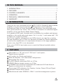
RECORDING STUDIO SET UP
UP
R
LTO
A1000.4
DRAGONFLY
ON
24 CLIP
26
20
18
22
24 CLIP
16
26
12
LIMIT
28
dB
SIG
20
18
22
24 CLIP
16
26
12
LIMIT
6
30
CH2
-
dB
30
6
SIG
20
22
24 CLIP
16
26
12
LIMIT
28
8
-
8
6
CH1
CH3
-
LIMIT
28
dB
30
6
SIG
CH4
-
28
8
18
22
12
OFF
8
20
18
16
POWER ON
dB
30
SIG
POWER
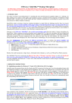
Also in this case, A1000.4 is connected to the CTRL ROOM output of the mixer
and drives four passive studio monitors such as the LTO MICRO4. There is plenty
of power even for bigger monitors still maintaining a very good headroom.
HOOK
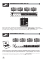
MULTIMEDIA SET UP
UP
R
LTO
A1000.4
DRAGONFLY
ON
18
22
24 CLIP
26
20
18
22
24 CLIP
16
26
12
LIMIT
28
dB
30
20
18
22
24 CLIP
16
26
12
LIMIT
6
SIG
CH2
-
28
8
-
8
6
CH1
dB
30
20
22
24 CLIP
16
26
12
LIMIT
6
SIG
CH3
-
28
dB
30
LIMIT
6
SIG
CH4
-
28
8
20
12
OFF
8
18
16
POWER ON
dB
30
SIG
POWER
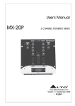
Today the advent of high-quality computer generated music creates the need
for hi-fi quality and high SPL audio reproduction. In this example, the A1000.4
is connected to the output of your computer sound card and drives two pairs
of advanced multimedia speakers such as the LTO MICRO4.
2
HOOK
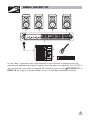
SMALL GIG SET UP
UP
R
LTO
A1000.4
DRAGONFLY
ON
18
22
24 CLIP
26
20
18
22
24 CLIP
16
26
12
LIMIT
28
dB
30
20
18
22
24 CLIP
16
26
12
LIMIT
6
SIG
CH2
-
28
8
-
8
6
CH1
dB
30
20
22
24 CLIP
16
26
12
LIMIT
6
SIG
CH3
-
28
dB
30
LIMIT
6
SIG
CH4
-
28
8
20
12
OFF
8
18
16
POWER ON
dB
30
SIG
POWER
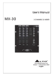
In this case, a passive mixer with different sound sources connected such as
microphone, keyboard and electric guitar send the main mix signal to the A1000.4.
You can connect two pairs of passive PA cabinets such as the LTO ELVIS 10 or
ELVIS 12 for a gig in a small pub/bar or for a small Band rehearsal session.
3
SP
OT
L
IG
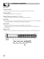
3. CONTROL ELEMENTS
HT
Front Panel:
1 Power On LED
This green LED will light up when you switch the A1000.4 ON.
2 Power Switch
To switch the A1000.4 ON and OFF.
3 Level Control for Channels 1, 2, 3 & 4
Adjust the output signal level of the respective channel.
4 Clip LED
It will flash when you are reaching the maximum power output of the amplifier.
It should flash only occasionally for optimum operation.
5 Limit LED
This LED will flash when the internal limiter is operating.
The limiter will prevent distortion and will protect the life of high frequency
transducers.
6 Signal LED
When a signal is applied to the input of your A1000.4, this LED will light up.
R
LTO
A1000.4
DRAGONFLY
ON
18
22
24 CLIP
26
20
18
22
24 CLIP
16
26
12
LIMIT
28
dB
30
20
18
22
24 CLIP
16
26
12
LIMIT
6
SIG
CH2
-
28
8
-
8
6
CH1
dB
30
20
22
24 CLIP
16
26
12
LIMIT
6
SIG
CH3
-
28
dB
30
LIMIT
6
SIG
CH4
-
28
8
20
12
OFF
8
18
16
POWER ON
dB
30
SIG
POWER
2
20
18
22
24 CLIP
26
20
18
22
24 CLIP
16
26
12
LIMIT
-
dB
30
6
SIG
CH2
-
28
8
CH1
28
8
6
20
18
22
24 CLIP
16
26
12
LIMIT
dB
30
6
SIG
20
CH3
-
28
24 CLIP
26
dB
30
LIMIT
6
SIG
CH4
-
28
dB
30
3
4
4
22
16
12
LIMIT
8
18
16
12
8
1
SIG
5
6
SP
OT
L
IG
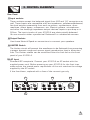
3. CONTROL ELEMENTS
HT
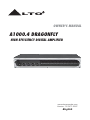
Rear Panel:
7 Input sockets
These sockets accept the balanced signal from XLR and 1/4" connectors as
well. These Inputs are compatible with low-impedance, unbalanced/balanced,
line-level outputs emanating from such as mixers, synthesizers, drum
machines, direct boxes, crossovers, etc. Electric guitars, microphones,
and other low level/high-impedance output devices require a pre-amp or a
D/I box. The input circuits of your A1000.4 are electronically balanced.
You can connect either symmetrical ("balanced") or unbalanced sources.
8 Output Sockets
Use these Neutrik Speak-on connectors to connect your speakers.
9 LIMITER Switch
The Limiter circuit will prevent the waveforms to be flattered thus preserving
a proper dynamic range and secure signal reproduction that is distortionfree. The Limiter status can be monitored from the limit led on the front
panel of your A1000.4.
10 AC Input
Standard IEC receptacle. Connect your A1000.4 an AC socket with the
supplied power cord. Before powering up your A1000.4 for the first time,
make certain the stated power requirement of the unit matches the voltage
supplied by the AC socket.
If the fuse blows, replaced with a fuse of the correct type only.
7
8
INPUT
10
Apparaten skall anslutas till
jordat uttag nar den ansluts
till ett natverk
POWER OUTPUT
CH1
CH3
LIMITER
LIMITER
OFF
ON
OFF
ON
CH2
CH4
AC INPUT
Use only with a 250V fuse
CH.1
CH.2
CH.3
CH.4
CH.1
CH.2
4
CH.3
SPEAKER LOAD MIN.
CH.4
AC INPUT 190-240V 50Hz
FUSE:T12AL 250VAC
Power Consumotion: 900W
9
5
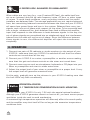
A DEEPER LOOK: BALANCED OR UNBALANCED?
When cables are very long (e.g., over 6 meters/20 feet), the cable itself can
act as an "antenna" and pick up radio frequency noise, AC hum, or other types
of noises. To avoid these problems, many recording studios and live sound
installers use balanced lines. The average application may not require balanced
lines, but committing balanced connectors between the mixer and your A1000.4
will cause less ground loops and hum in the system. Balanced lines carry two
signals, each one out of phase with respect to the other. To be converted back
into a single, unbalanced line, both balanced lines feed a differential amplifier
input that responds to the difference in levels between signals. In this way, the
out-of-phase signals are recombined into an unbalanced signal, but interference
induced into the cable will not be out of phase. Since the difference between
these signals is zero, the differential amplifier will reject the interference
completely.
4. OPERATION
1. Connect two pairs of PA cabinets or studio monitors to the output of your
A1000.4. make sure that your A1000.4 is switched off and that the volume
controls are turned down all the way.
2. Connect your A1000.4 to a mixer, a preamplifier or another source making
sure that the gain and volume controls on the mixer are turned down.
3. Connect some source such as microphones, keyboards or CD player into your
Mixer or preamplifier and start to make some noise.
4. Adjust the output level of your mixer or preamplifier at a proper level. A very
low output level will generate unwanted noise.
At this point, gradually turn up the volumes in your A1000.4 making sure that
the limit LEDs only flash occasionally.
!
Notice
OPERATION ADVICES:
4.1 TEMPERATURE CONSIDERATION IN RACK MOUNTING:
You can mount your A1000.4 in only 1.5U with the special optional brackets.
Although your A1000.4 generates almost no heat at all, you must secure proper
ventilation inside the rack to avoid overheating.
A sustained high-temperature operation will adversely affect the sound quality,
and the amplifier may shut itself off for as long as the excessive temperature
conditions exist.
6
4.2 IMPEDANCE
Your A1000.4 will easily drive 4 Ohm loads in Stereo mode.
However, the impedance of any loudspeaker changes with
frequency, and its rated impedance is not always its minimum
impedance.
If you connect more than one loudspeaker to the A1000.4, please check that
the actual load impedance does not drop below the A1000.4's rated output load
that is 4 Ohm. Your A1000.4 will not be damaged by excessively low output load
impedances, but will not be able to provide full output power and its protection
circuit will automatically cut off the output signal until the low load condition
is removed.
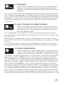
4.3 HOW TO CHOOSE THE CORRECT SPEAKER
Today it has become very popular to monitor and mix music
through near-field monitors "reference" speakers. With near
field monitoring, small speakers are positioned a few feet
from the engineer's ears.
As a consequence, the acoustic is not so critical. Near-field monitors offer
more advantages when compared to large studio monitor, such as smaller size
and lower cost.
Because of its optimal power rating, HI-FI performance, and a no-fan design,
your A1000.4 is ideal in driving reference near-field monitor speakers in smaller
studios.
Your A1000.4 is also at home driving high frequency compression drivers or
full range PA cabinets or Stage Monitors when enormous SPL is not required.
4.4 POWER CONSIDERATION
Digital amplifiers and switch mode power supply (which are
parts of your A1000.4) are designed to reproduce musical
signals with high dynamics, high SPL and low distortion. For
this reason, all major Manufacturers of these kinds of amplifiers do not specify
their amps in terms of RMS but most measurements are made with EIA (or
EIAJ) specifications. An EIAJ signal (you can download the signal string from
the site of Electronic Industry Association) simulates a musical signal and it is
applied to the input of LTO amplifier continuously, that is for a long period of
time. Under EIA specification, your A1000.4 will deliver 250 watt channel
continuously with 240 Volt as AC power and with one channel at a time driven.
But switch mode power supply like the one used in your A1000.4 are capable
of enormous dynamics and therefore we also measure your A1000.4 as "dynamic
power". This is the amplifier capability to deliver a very high "dynamic power" for
short periods of time securing unprecedent SPL with transient sounds. In this
case the total dynamic power of your A1000.4 is 450 watt channel on 4 Ohm.
7
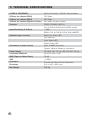
5. TECHNICAL SPECIFICATIONS
A1000.4 DRAGONFLY
20 Hz 20 kHz@ 0.1%THD, Stereo Mode
8 Ohms per channel (EIAJ)
150 Watt
4 Ohms per channel (EIAJ)
250 Watt
4 Ohms per channel (Dynamic Power)
450 Watt (PEAK POWER)
Controls
FRONT: POWER SWITCH,
CH1 & CH2 & CH3 & CH4 LEVEL knobs
Input Sensitivity @ 4 Ohms
+3dBu
REAR: CH1 & CH2 & CH3 & CH4 LIMITER
Indicators (per channel)
Power-On: Green LED
Clip: Red LED
Limit: Yellow LED
Signal: Green LED
Connectors of each channel
Input: COMBO connector
Output: Neutrik Speak-on connector
Power Supply
190-240 VAC~50 Hz / 95-120 VAC~60 Hz
Frequency Response
20 Hz-20 kHz+3 dB
SNR (Signal to Noise Ratio)
76 dB
THD
<0.35%
Protection
Thermal and Short Circuit Protection
Dimension
314 x 440 x 66.6 mm
Net Weight
6.8 Kg
8
6. WARRANTY
1. WARRANTY REGISTRATION CARD
To obtain Warranty Service, the buyer should first fill out and return the enclosed
Warranty Registration Card within 10 days of the Purchase Date.
All the information presented in this Warranty Registration Card gives the
manufacturer a better understanding of the sales status, so as to provide a
more effective and efficient after-sales warranty service. Please fill out all the
information carefully and genuinely, miswriting or absence of this card will void
your warranty service.
2. RETURN NOTICE
2.1 In case of return for any warranty service, please make sure that the
product is well packed in its original shipping carton, and it can protect your
unit from any other extra damage.
2.2 Please provide a copy of your sales receipt or other proof of purchase with
the returned machine, and give detail information about your return address
and contact telephone number.
2.3 A brief description of the defect will be appreciated.
2.4 Please prepay all the costs involved in the return shipping, handling and
insurance.
3. TERMS AND CONDITIONS
3.1 LTO warrants that this product will be free from any defects in materials
and/or workmanship for a period of 1 year from the purchase date if you
have completed the Warranty Registration Card in time.
3.2 The warranty service is only available to the original consumer, who purchased
this product directly from the retail dealer, and it can not be transferred.
3.3 During the warranty service, LTO may repair or replace this product at its
own option at no charge to you for parts or for labor in accordance with the
right side of this limited warranty.
3.4 This warranty does not apply to the damages to this product that occurred
as the following conditions:
Instead of operating in accordance with the user's manual thoroughly, any abuse
or misuse of this product.
Normal tear and wear.
The product has been altered or modified in any way.
Damage which may have been caused either directly or indirectly by another
product / force / etc.
Abnormal service or repairing by anyone other than the qualified personnel or
technician.
And in such cases, all the expenses will be charged to the buyer.
3.5 In no event shall LTO be liable for any incidental or consequential damages.
Some states do not allow the exclusion or limitation of incidental or
consequential damages, so the above exclusion or limitation may not apply to
you.
3.6 This warranty gives you the specific rights, and these rights are compatible
with the state laws, you may also have other statutory rights that may vary
from state to state.
9
SEIKAKU TECHNICAL GROUP LIMITED
NO. 1, Lane 17, Sec. 2, Han Shi West Road, Taichung 40151, Taiwan
http://www.altoproaudio.com Tel: 886-4-22313737
email: [email protected] Fax: 886-4-22346757
All rights reserved to ALTO. All features and content might be changed
without prior notice. Any photocopy, translation, or reproduction of part of this
manual without written permission is forbidden. Copyright c 2007 Seikaku Group
NF02215-1.2