1
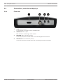
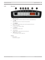
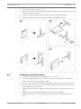
VIDEOJET decoder 3000
VJD-3000
en
Installation Manual
VIDEOJET decoder 3000
Table of Contents | en
3
Table of contents
1
Safety
5
1.1
Electric shock hazard
5
1.2
Installation and operation
5
1.3
Maintenance and repair
6
2
Short information
7
2.1
About this manual
7
2.2
Conventions in this manual
7
2.3
Intended use
7
2.4
EU Directives
7
2.5
Rating plate
7
3
System overview
8
3.1
Parts included
8
3.2
System requirements
8
3.3
Overview of functions
3.4
Connections, controls and displays
10
3.4.1
Front view
10
3.4.2
Rear view
11
4
Installation
12
4.1
Preparations
12
4.2
Mounting
12
4.3
Installing in a switch cabinet
13
5
Connection
15
5.1
Connecting monitors
15
5.2
Connecting audio
16
5.3
Establishing the network connection
17
5.4
Connecting alarm inputs and relay output
17
5.5
Creating a serial connection
18
5.6
Connecting the power supply
19
6
Configuration
21
6.1
Setup
21
6.2
Setup using Bosch Video Client
21
7
Troubleshooting
23
7.1
Contact
23
8
7.2
General malfunctions
23
7.3
LEDs
24
7.4
Processor load
25
7.5
Network connections
25
7.6
Terminal block
25
7.7
Copyrights
26
8
Maintenance
27
8.1
Updates
27
8.2
Factory reset
27
8.3
Repairs
27
9
Decommissioning
28
9.1
Transfer
28
9.2
Disposal
28
Bosch Sicherheitssysteme GmbH
Installation Manual
2014.01 | V4 | F.01U.296.741
4
en | Table of Contents
VIDEOJET decoder 3000
10
Technical data
29
10.1
Electrical
29
10.2
Mechanical
29
10.3
Environmental conditions
29
10.4
Standards
30
Index
31
2014.01 | V4 | F.01U.296.741
Installation Manual
Bosch Sicherheitssysteme GmbH
VIDEOJET decoder 3000
Safety | en
1
Safety
1.1
Electric shock hazard
–
5
Never attempt to connect the unit to any power network other than the type for which it
is intended.
–
Use only the power supply provided or power supply units with UL approval and a power
output according to LPS or NEC Class 2.
–
Connect the unit to an earthed mains socket-outlet.
–
Never open the housing.
–
Never open the housing of the power supply unit.
–
If a fault occurs, disconnect the power supply unit from the power supply and from all
other units.
–
Install the power supply and the unit only in a dry, weather-protected location.
–
When installing in a switch cabinet, ensure that the unit and the power supply units have
sufficient grounding.
–
If safe operation of the unit cannot be ensured, remove it from service and secure it to
prevent unauthorized operation. In such cases, have the unit checked by Bosch Security
Systems.
Safe operation is no longer possible in the following cases:
1.2
–
if there is visible damage to the unit or power cables,
–
if the unit no longer operates correctly,
–
if the unit has been exposed to rain or moisture,
–
if foreign bodies have penetrated the unit,
–
after long storage under adverse conditions, or
–
after exposure to extreme stress in transit.
Installation and operation
–
The relevant electrical engineering regulations and guidelines must be complied with at
all times during installation.
–
Relevant knowledge of network technology is required to install the unit.
–
Before installing or operating the unit, make sure you have read and understood the
documentation for the other equipment connected to it, such as monitors. The
documentation contains important safety instructions and information about permitted
uses.
–
Perform only the installation and operation steps described in this manual. Any other
actions may lead to personal injury, damage to property or damage to the equipment.
Please ensure the following installation conditions:
–
Do not install the unit or the power supply unit close to heaters or other heat sources.
Avoid locations exposed to direct sunlight.
–
Allow sufficient space for running cables.
–
Ensure that both the unit and the power supply unit have adequate ventilation. Bear the
total heat output in mind, particularly when installing multiple units in a switch cabinet.
–
When making connections, use only the cables supplied or use appropriate cables
immune to electromagnetic interference.
–
Position and run all cables so that they are protected from damage, and provide adequate
cable strain relief where needed.
–
When installing in a switch cabinet, ensure that the screw joints are free of tension and
subject to as little mechanical stress as possible. Ensure that the unit and the power
supply unit have sufficient grounding.
Bosch Sicherheitssysteme GmbH
Installation Manual
2014.01 | V4 | F.01U.296.741
6
en | Safety
VIDEOJET decoder 3000
–
Avoid impacts, blows, and severe vibrations that exceed the specification limits, as these
can irreparably damage the unit.
1.3
Maintenance and repair
–
Never open the housing of the unit. The unit does not contain any user-serviceable parts.
–
Never open the housing of the power supply unit. The power supply unit does not contain
any user-serviceable parts.
–
Ensure that all maintenance or repair work is carried out only by qualified personnel
(electrical engineers or network technology specialists). In case of doubt, contact your
dealer's technical service center.
2014.01 | V4 | F.01U.296.741
Installation Manual
Bosch Sicherheitssysteme GmbH
VIDEOJET decoder 3000
Short information | en
2
Short information
2.1
About this manual
7
This manual is intended for persons responsible for the installation and operation of a
VIDEOJET decoder 3000 unit. International, national and any regional electrical engineering
regulations must be followed at all times. Relevant knowledge of network technology is
required. The manual describes the installation of the unit.
2.2
Conventions in this manual
In this manual, the following symbols and notations are used to draw attention to special
situations:
Caution!
!
This symbol indicates that failure to follow the safety instructions described may endanger
persons and cause damage to the unit or other equipment.
It is associated with immediate, direct hazards.
Notice!
This symbol refers to features and indicates tips and information for easier, more convenient
use of the unit.
2.3
Intended use
VIDEOJET decoder 3000 receives and decodes video signals over data networks (Ethernet
LAN, Internet). The unit is intended for use with CCTV systems. Various functions can be
triggered automatically by incorporating external alarm sensors. Other applications are not
permitted.
In the event of questions concerning the use of the unit which are not answered in this
manual, please contact your sales partner or:
Bosch Sicherheitssysteme GmbH
Robert-Bosch-Ring 5
85630 Grasbrunn
Germany
www.boschsecurity.com
2.4
EU Directives
VIDEOJET decoder 3000 complies with the requirements of EU Directives 89/336
(Electromagnetic Compatibility) and 73/23, amended by 93/68 (Low Voltage Directive).
2.5
Rating plate
For exact identification, the model name and serial number are inscribed on the bottom of the
housing. Please make a note of this information before installation, if necessary, so as to have
it to hand in case of questions or when ordering spare parts.
Bosch Sicherheitssysteme GmbH
Installation Manual
2014.01 | V4 | F.01U.296.741
8
en | System overview
VIDEOJET decoder 3000
3
System overview
3.1
Parts included
–
1 VIDEOJET decoder 3000 video decoder
–
2 terminal blocks (6-pin, 8-pin)
–
4 self-adhesive elastic bumpers
–
1 wall-mounting panel
–
2 screws
–
2 wall plugs
–
1 power supply unit with 3 primary adapters (EU, US, UK)
–
1 Installation Manual
Notice!
Check that the delivery is complete and in perfect condition. Arrange for the unit to be
checked by Bosch Security Systems if you find any damage.
3.2
System requirements
General requirements
–
Computer with Windows XP or Windows 7 operating system
–
Network access (Intranet or Internet)
–
Screen resolution at least 1,024 × 768 pixels
–
16- or 32-bit color depth
–
Installed Oracle JVM
Notice!
The Web browser must be configured to enable cookies to be set from the IP address of the
unit.
In Windows 7, deactivate protected mode on the Security tab under Internet Options.
You can find notes on using Microsoft Internet Explorer in the online Help in Internet
Explorer.
Additional configuration and operational requirements
You find the information on additional configuration and operational requirements in the
Releaseletter document for the respective firmware.
For the latest version of the firmware, required programs and controls, and the current version
of the Bosch Video Client management software, access your Bosch product catalog on the
Internet.
3.3
Overview of functions
High Definition video decoder
VIDEOJET decoder 3000 displays H.264 encoded video at up to 60 images per second from
PAL, NTSC, or HD sources over IP networks.
Establish the video connections automatically from the camera, encoder, decoder, or the
comprehensive video management system from Bosch. The decoder is capable of decoding a
single HD video stream, or up to four SD video streams at the same time in quad-mode.
Control the viewing mode remotely via a management system. It can drive an HD monitor via
HDMI directly, thus is ideally suited for applications like flat-screen monitor walls.
Alternatively, it can connect to an analogue monitor using its composite video BNC output.
2014.01 | V4 | F.01U.296.741
Installation Manual
Bosch Sicherheitssysteme GmbH
System overview | en
VIDEOJET decoder 3000
9
VIDEOJET decoder 3000 provides one-channel bidirectional audio communication in parallel
to video.
Ultra-compact in size, VIDEOJET decoder 3000 is perfect for any application that depends on
space-saving solutions.
Access security
VIDEOJET decoder 3000 offers various security levels for accessing the network, the unit, and
the data channels. As well as password protection with two levels, it supports 802.1x
authentication using a RADIUS server for identification. You can secure Web browser access
by HTTPS using a SSL certificate that is stored in the unit, providing total data protection with
AES or 3DES encryption, according to the client's encryption capabilities. Alternatively, each
communication channel—video, audio, or serial I/O—can be independently AES encrypted with
128‑bit keys, once the encryption site license has been applied.
High performance
Transmit IP video to the high-performance decoder and present it with ultimate clarity on an
analog CCTV monitor or on a large, flat-screen display.
VIDEOJET decoder 3000 can handle up to four SD H.264 video streams with full resolution
and frame rate and display them in quad-view. When in single-view, it can display an HD video
stream up to 1080p30 or 720p60.
Flexibility
With its connection page in the web browser, the optional IP Matrix license, the support of
IntuiKey keyboard and integration into video clients and video management systems,
VIDEOJET decoder 3000 enables solutions in varieties from the smallest stand-alone up to
large or distributed but centrally controlled applications.
Easy upgrade
Remotely upgrade the unit whenever new firmware becomes available. This ensures up-to-date
products, thus protecting investment with little effort.
Summary
VIDEOJET decoder 3000 provides the following main functions:
–
Video, audio, and data reception over IP data networks
–
Quad view function with simultaneous decoding of four video streams
–
1 BNC composite video output (PAL/NTSC) for connecting an analog monitor
–
1 HDMI interface to display digital video on flat-screen monitors or the like
–
Video decoding according to international standard H.264
–
Integrated Ethernet port (10/100 Base-T)
–
Transparent, bidirectional data channel via RS-232/RS-422/RS-485 serial interface
–
Configuration and remote control of all internal functions via TCP/IP, also secured via
HTTPS
–
Password protection to prevent unauthorized connection or configuration changes
–
4 alarm inputs for external sensors (such as door contacts)
–
1 relay output for switching external units (such as lamps or sirens)
–
Event-controlled automatic connection
–
Convenient maintenance via uploads
–
Flexible encryption of control and data channels
–
Authentication according to international standard 802.1x
–
Bidirectional audio (mono) for line connections
–
Audio encoding according to international standards G.711 and L16
Bosch Sicherheitssysteme GmbH
Installation Manual
2014.01 | V4 | F.01U.296.741
10
en | System overview
VIDEOJET decoder 3000
3.4
Connections, controls and displays
3.4.1
Front view
1
HDMI monitor socket
for connecting a computer monitor via HDMI cable
2
VIDEO OUT video output
BNC socket for connecting a video monitor
3
AUDIO IN audio connection (mono)
3.5 mm (1/8 in) stereo socket audio in for connecting two audio sources
4
AUDIO OUT audio connection (mono)
3.5 mm (1/8 in) stereo socket line-out for connecting one audio connection
2014.01 | V4 | F.01U.296.741
Installation Manual
Bosch Sicherheitssysteme GmbH
VIDEOJET decoder 3000
3.4.2
System overview | en
11
Rear view
1
ETH RJ45 socket
for connecting to an Ethernet LAN (local network), 10/100 MBit Base-T
2
LED LINK
lights up when the unit is connected to the network
3
LED CONNECT
lights up when supplied with power and during data transmission
4
Factory reset button
to restore factory default settings
5
LED DISPLAY
indicates use of monitor ports
6
Terminal block
for alarm inputs, relay output and serial interface
7
12V DC power connector
for connecting the power supply unit
See also
–
LEDs, page 24
–
Terminal block, page 25
Bosch Sicherheitssysteme GmbH
Installation Manual
2014.01 | V4 | F.01U.296.741
12
en | Installation
VIDEOJET decoder 3000
4
Installation
4.1
Preparations
VIDEOJET decoder 3000 and the power supply unit are both intended for use indoors or in
housings. Select a suitable location for installation that guarantees to meet the environmental
conditions.
You may use the unit as a desktop device or wall-mounted using the mounting material
supplied. For installation in a switch cabinet, you can obtain a rack mount kit for up to three
units. For more information access your Bosch product catalog on the Internet.
Caution!
The ambient temperature for the delivered power supply unit must be between 0 and +40 °C
(+32 and +104 °F). The relative humidity must be between 20% and 80%. The ambient
temperature for the unit must be between 0 and +50 °C (+32 and +122 °F). The relative
!
humidity must not exceed 90%.
The unit and the power supply unit generate heat during operation, so you should ensure that
there is adequate ventilation and enough clearance between both units and heat-sensitive
objects or equipment. Please note the maximum heat value of 31 BTU/h per unit without the
power supply.
Please ensure the following installation conditions:
–
Do not install the unit or the power supply unit close to heaters or other heat sources.
Avoid locations exposed to direct sunlight.
–
Allow sufficient space for running cables.
–
Ensure that both the unit and the power supply unit have adequate ventilation. Bear the
total heat output in mind, particularly when installing multiple units in a switch cabinet.
–
When making connections, use only the cables supplied or use appropriate cables
immune to electromagnetic interference.
–
Position and run all cables so that they are protected from damage, and provide adequate
cable strain relief where needed.
–
When installing in a switch cabinet, ensure that the screw joints are free of tension and
subject to as little mechanical stress as possible. Ensure that the unit and the power
supply unit have sufficient grounding.
–
Avoid impacts, blows, and severe vibrations that exceed the specification limits, as these
can irreparably damage the unit.
Mounting
4.2
You can secure the unit to walls, below ceilings or any other load-bearing locations using the
wall-mounting panel, in either a vertical or a horizontal position.
Caution!
!
The mounting location must be able to reliably hold the unit. The load-bearing capacity must
be adequate for four times the weight of the unit.
If mounting the unit in a vertical position, you will need to use the lower plastic frame and
then place the unit onto the frame from above. If mounting the unit in a horizontal position,
you can use either of the two frames.
1.
Lift the plastic frame on one side of the housing and carefully remove it from the unit.
2.
Screw the plastic frame in the required position together with the wall-mounting panel.
2014.01 | V4 | F.01U.296.741
Installation Manual
Bosch Sicherheitssysteme GmbH
VIDEOJET decoder 3000
Installation | en
13
3.
Check that the plastic frame is secure.
4.
Place the unit on the wall-mounting panel, with the panel positioned between the housing
and the second plastic frame.
4.3
5.
Slide the unit into the plastic frame until you feel it lock securely into place.
6.
Finally, check that the unit is securely attached in the installation location.
Installing in a switch cabinet
1.
Install the required number of fixing plates, two for each unit.
2.
Prepare the switch cabinet in such a manner that you are easily able to insert the rack
mount frame directly at the installation point.
3.
Place the cage nuts in the corresponding drillings or spaces in the switch cabinet frame.
4.
Lift the empty rack mount frame into the switch cabinet frame and insert the fastening
screws together with the washers.
5.
Tighten the screws one after the other and then check once more that all the screws are
tight.
6.
Remove the plastic frames from both sides of each unit to be installed.
7.
Slide each unit onto the corresponding fixing plates until you feel it lock securely into
place.
Bosch Sicherheitssysteme GmbH
Installation Manual
2014.01 | V4 | F.01U.296.741
14
en | Installation
2014.01 | V4 | F.01U.296.741
VIDEOJET decoder 3000
Installation Manual
Bosch Sicherheitssysteme GmbH
VIDEOJET decoder 3000
Connection | en
5
Connection
5.1
Connecting monitors
15
You must connect a suitable monitor to the decoder. The unit provides two monitor outputs.
Simultaneous use of both outputs is possible once you have set the video standard to PAL or
NTSC.
Notice!
The default setting for the video standard is PAL. Display may not work properly if you
connect other than PAL monitors without adapting the corresponding setting.
Make sure that the cables used do not exceed the maximum length of 30 m (98 ft).
1.
Connect an analog video monitor (PAL/NTSC) to the BNC socket VIDEO OUT using a
video cable (75 ohm, BNC plug).
2.
Connect an HDMI-compatible computer monitor to the HDMI socket using an HDMI cable.
Note: No audio is supported via the HDMI connection. Use the audio ports if you need
audio transmission.
Using an HDMI-DVI adapter, you can also connect a DVI monitor via the HDMI socket.
Bosch Sicherheitssysteme GmbH
Installation Manual
2014.01 | V4 | F.01U.296.741
16
5.2
en | Connection
VIDEOJET decoder 3000
Connecting audio
The unit has two audio ports for audio line signals.
The audio signals are transmitted two-way and in sync with the video signals. The following
specifications should be complied with in all cases.
2 × audio in:
Impedance 9 kohm typ., 5.5 Vp-p max. input voltage
1 × line out:
3.0 Vp-p typ. output voltage at 10 kohm impedance
The stereo plug must be connected as follows:
Contact
AUDIO IN
AUDIO OUT
Tip
Channel 1
Channel 1
Middle ring
Channel 2
—
Lower ring
Ground
Ground
1.
Connect an audio source to the AUDIO IN socket with a 3.5 mm (1/8 in) stereo plug.
2.
Connect an audio receiver with line-in connection to the AUDIO OUT socket with a
3.5 mm (1/8 in) stereo plug.
Note that the audio function is not activated by default. To use audio connections activate the
corresponding setting when configuring the unit.
2014.01 | V4 | F.01U.296.741
Installation Manual
Bosch Sicherheitssysteme GmbH
VIDEOJET decoder 3000
5.3
Connection | en
17
Establishing the network connection
You can connect the unit to a 10/100 Base-T network using a standard UTP category 5 cable
with RJ45 plugs.
4
5.4
Connect the unit to the network via the ETH socket.
Connecting alarm inputs and relay output
Alarm inputs
The unit has 4 alarm inputs on the terminal block. The alarm inputs are used to connect to
external alarm devices such as door contacts or sensors. With the appropriate configuration,
an alarm sensor can automatically connect the unit to a remote location, for example.
A zero potential closing contact or switch can be used as the actuator. If possible, use a
bounce-free contact system as the actuator.
Bosch Sicherheitssysteme GmbH
Installation Manual
2014.01 | V4 | F.01U.296.741
18
en | Connection
VIDEOJET decoder 3000
Caution!
!
Please observe the labeling on the unit.
1.
Connect the lines to the appropriate terminals on the terminal block (IN1 to IN4) and
check that the connections are secure.
2.
Connect each alarm input to a ground contact (GND).
Relay output
The unit has one relay output for switching external units such as lamps or alarm sirens. You
can operate the relay output manually while there is an active connection to the unit. The
output can also be configured to automatically activate sirens or other alarm units in response
to an alarm signal. The relay output is also located on the terminal block.
Caution!
!
Please observe the labeling on the unit.
A maximum load of 30 Vp-p (SELV) and 200 mA may be applied to the relay contacts.
1.
Connect the lines to the appropriate terminals R on the terminal block and check that the
connections are secure.
2.
Connect the terminal block to the socket on the unit observing the labeling.
See also
–
5.5
Terminal block, page 25
Creating a serial connection
The bidirectional data interface is used to control units connected to the decoder, such as a
control panel for a dome cameras with motorized lens. The connection supports the RS-232,
RS-422, and RS-485 transmission standards. A video connection is necessary to transmit
transparent data.
The serial interface is also located on the terminal block.
2014.01 | V4 | F.01U.296.741
Installation Manual
Bosch Sicherheitssysteme GmbH
VIDEOJET decoder 3000
Connection | en
19
The range of controllable equipment is expanding constantly. The manufacturers of the
relevant equipment provide specific information on installation and control. Please take note
of the appropriate documentation when installing and operating the peripheral to be
controlled. The documentation contains important safety instructions and information about
permitted uses.
Caution!
!
Please observe the labeling on the unit.
1.
If you require a serial connection to the unit, connect the relevant cables to the terminal
block and check that the connections are secure.
2.
Connect the terminal block to the socket on the unit observing the labeling.
See also
–
5.6
Terminal block, page 25
Connecting the power supply
VIDEOJET decoder 3000 comes with a plug-in power supply unit with three primary adapters.
It does not have a power switch. The unit is ready for operation as soon as it is connected to
the mains.
Bosch Sicherheitssysteme GmbH
Installation Manual
2014.01 | V4 | F.01U.296.741
20
en | Connection
VIDEOJET decoder 3000
Caution!
Make sure to use the power supply unit provided only with the correct primary adapter for
your power outlet or use another power supply unit with UL approval and a power output
!
according to LPS or NEC Class 2.
Where necessary, use suitable equipment to ensure that the power supply is free from
interference such as voltage surges, spikes or voltage drops.
Do not connect the decoder to the power supply until all other connections have been made.
1.
Connect the power supply unit to the 12V DC socket.
2.
Ensure that the correct primary adapter is attached to the power supply unit and that a
suitable power outlet is available.
3.
Plug the power supply unit into the grounded power outlet. The unit is ready for use as
soon as the CONNECT LED changes from a red light, indicating the start-up procedure, to
a green light.
Provided the network connection has been correctly made, the green LINK LED also lights up.
The flashing green CONNECT LED signals that data packets are being transmitted via the
network.
See also
–
2014.01 | V4 | F.01U.296.741
LEDs, page 24
Installation Manual
Bosch Sicherheitssysteme GmbH
VIDEOJET decoder 3000
Configuration | en
6
Configuration
6.1
Setup
21
Before you can operate the unit within your network, it must have a valid IP address for your
network and a compatible subnet mask.
Notice!
As a default DHCP is enabled in the unit’s network settings.
With an active DHCP server in the network you must know the IP address assigned by the
DHCP server to operate the unit.
The following default address is preset at the factory: 192.168.0.1
The setup procedure is carried out via our Video Client software or other management
systems. All information regarding the configuration can be found in the relevant
documentation of the video management system in use.
6.2
Setup using Bosch Video Client
For the current version of our Video Client management software, access your Bosch product
catalog on the Internet. This program allows you to implement and set up the unit in the
network quickly and conveniently.
Installing the program
1. Download Video Client from the Bosch product catalog on the Internet.
2.
Unzip the file.
3.
Double-click the installer file.
4.
Follow the instructions on the screen to complete the installation.
Configuring the unit
You can start Video Client immediately after installation.
1.
Double-click the
icon on the desktop to start the program. Alternatively, start
the application via the Start button and the Programs menu (path: Start/Programs/
Bosch Video Client/Bosch Video Client).
2.
When the program is started for the first time, a wizard opens to help you detect and
configure devices on the network.
3.
If the wizard does not start automatically, click
to open the Configuration Manager
application. Then, click Configuration Wizard... on the Tools menu.
4.
Follow the instructions given in the Configuration Wizard window.
Bosch Sicherheitssysteme GmbH
Installation Manual
2014.01 | V4 | F.01U.296.741
22
en | Configuration
VIDEOJET decoder 3000
Additional parameters
You can check and set additional parameters with the assistance of the Configuration Manager
application in Bosch Video Client. You can find detailed information on this in the
documentation for these applications.
Note that the audio function is not activated by default. To use audio connections activate the
corresponding setting when configuring the unit.
2014.01 | V4 | F.01U.296.741
Installation Manual
Bosch Sicherheitssysteme GmbH
VIDEOJET decoder 3000
Troubleshooting | en
7
Troubleshooting
7.1
Contact
23
If you are unable to resolve a malfunction, please contact your supplier or systems integrator,
or go directly to Bosch Security Systems Customer Service.
The following tables are intended to help you identify the causes of malfunctions and correct
them where possible.
7.2
General malfunctions
Malfunction
Possible causes
Recommended solution
No image on the
Monitor error.
Connect local camera or other
monitor.
video source to the monitor
and check the monitor
function.
Faulty cable connections.
Check all cables, plugs,
contacts and connections.
Monitor fault.
Connect another monitor to the
unit or use another monitor
connection.
Incorrect configuration.
Check video standard settings
to match the monitor.
No connection
The unit's configuration.
established, no image
transmission.
Check all configuration
parameters.
Faulty installation.
Check all cables, plugs,
contacts and connections.
Wrong IP address.
Check the IP addresses.
Faulty data transmission within
Check the data transmission
the LAN.
with e.g. ping.
The maximum number of
Wait until there is a free
connections has been reached.
connection and then call the
sender again.
No audio transmission to Hardware fault.
Check that all connected audio
remote station.
units are operating correctly.
Faulty cable connections.
Check all cables, plugs,
contacts and connections.
Incorrect configuration.
Check audio parameters.
The audio connection is already Wait until the connection is
in use by another receiver.
free and then call the unit
again.
The unit does not report
Alarm source is not selected.
Check alarm source settings.
an alarm.
Bosch Sicherheitssysteme GmbH
Installation Manual
2014.01 | V4 | F.01U.296.741
24
en | Troubleshooting
Malfunction
VIDEOJET decoder 3000
Possible causes
Recommended solution
No alarm response specified.
Specify the desired alarm
response, change the IP
address, if necessary.
Control of cameras or
The cable connection between
Check all cable connections
other units is not
the serial interface and the
and ensure all plugs are
possible.
connected unit is not correct.
properly fitted.
The interface parameters do
Make sure that the settings of
not match those of the other
all units involved are
unit connected.
compatible.
The unit is not
Power failure during
Have the unit checked by
operational after a
programming by firmware file.
Customer Service and replace
firmware upload.
it, if necessary.
Incorrect firmware file.
Enter the IP address of the unit
followed by /main.htm in your
Web browser and repeat the
upload.
Placeholder with a red
JVM not installed on your
Install Oracle JVM from the
cross instead of the
computer or not activated.
Bosch product catalog on the
ActiveX components.
Web browser contains
Internet.
Active proxy server in network.
empty fields.
Create a rule in the local
computer's proxy settings to
exclude local IP addresses.
If a sender is connected
Auto-connect configured.
Deactivate auto-connect.
to the decoder, the first
connection remains.
7.3
LEDs
The unit has LEDs on its rear panel that show the operating status and can give indications of
possible malfunctions:
LINK LED
Lights up green:
Network connection established.
CONNECT LED
Does not light up:
The unit is switched off.
Lights up green:
The unit is switched on and startup completed.
Lights up red:
Startup in progress.
Flashes green:
Data packet transmission via network.
Flashes red:
The unit is faulty, for example following failed firmware
upload.
DISPLAY LED
Flashes green:
Both analog and digital video can be connected.
Lights up green:
Only digital video available.
2014.01 | V4 | F.01U.296.741
Installation Manual
Bosch Sicherheitssysteme GmbH
VIDEOJET decoder 3000
7.4
Troubleshooting | en
25
Processor load
If the unit is accessed via the Web browser, you will see the processor load indicator bar in
the top right of the window next to the information icon
.
You can obtain additional information to help you when troubleshooting or fine tuning the
unit. The values indicate the proportions of the individual functions on the coder load, shown
as percentages.
Move the cursor over the graphic indicator. Some additional numerical values are also
4
displayed.
7.5
Network connections
You can display information about the network connection. To do this, move the cursor over
.
7.6
Link
Ethernet link type
UL
Uplink, speed of the outgoing data traffic
DL
Downlink, speed of the incoming data traffic
Terminal block
The terminal block has several contacts for:
–
Serial data transmission
–
4 alarm inputs
–
1 relay output
Pin assignment serial interface
Options for using the serial interface include transferring transparent data, controlling
connected units or operating the unit with a terminal program.
The serial interface supports the RS-232, RS-422 and RS-485 transmission standards. The
mode used depends on the current configuration.
The pin assignment of the serial interface depends on the interface mode used:
Contact
RS-232 mode
RS-422 mode
RS-485 mode
CTS
—
RxD- (receive data minus)
—
TXD
TxD (transmit data)
TxD- (transmit data minus)
Data-
RTS
—
TxD+ (transmit data plus)
Data+
RXD
RxD (receive data)
RxD+ (receive data plus)
—
GND
GND (ground)
—
—
Bosch Sicherheitssysteme GmbH
Installation Manual
2014.01 | V4 | F.01U.296.741
26
en | Troubleshooting
VIDEOJET decoder 3000
Pin assignment I/O
Contact
Function
IN1
Input alarm 1
IN2
Input alarm 2
IN3
Input alarm 3
IN4
Input alarm 4
GND
Ground
R
Relay output
Connect each alarm input to a ground contact (GND).
7.7
Copyrights
The terms HDMI and HDMI High-Definition Multimedia Interface, and the HDMI logo are
trademarks or registered trademarks of HDMI Licensing LLC in the United States and other
countries.
Fonts
The firmware uses the fonts "Adobe-Helvetica-Bold-R-Normal--24-240-75-75-P-138-ISO10646-1"
and "Adobe-Helvetica-Bold-R-Normal--12-120-75-75-P-70-ISO10646-1" under the following
copyright:
Copyright 1984-1989, 1994 Adobe Systems Incorporated.
Copyright 1988, 1994 Digital Equipment Corporation.
Permission to use, copy, modify, distribute and sell this software and its documentation for
any purpose and without fee is hereby granted, provided that the above copyright notices
appear in all copies and that both those copyright notices and this permission notice appear
in supporting documentation, and that the names of Adobe Systems and Digital Equipment
Corporation not be used in advertising or publicity pertaining to distribution of the software
without specific, written prior permission.
Software
This software is based in part on the work of the Independent JPEG Group.
2014.01 | V4 | F.01U.296.741
Installation Manual
Bosch Sicherheitssysteme GmbH
VIDEOJET decoder 3000
Maintenance | en
8
Maintenance
8.1
Updates
27
Firmware updates are carried out via our Video Client software or other management systems
in use. Please refer to the relevant documentation.
8.2
Factory reset
You can use the factory reset button to restore the unit to its original settings. Any changes to
the settings are overwritten by the factory defaults. A reset may be necessary, for example, if
the unit has invalid settings that prevent it from functioning as desired.
1.
Using a pointed object, press the factory reset button located on the rear panel until the
CONNECT LED flashes red. All settings will revert to their defaults.
2.
The unit is ready for use as soon as the CONNECT LED lights up green.
P
The unit can now only be addressed via the factory default IP 192.168.0.1: reconfigure it
to your needs.
8.3
Repairs
–
Never open the housing of the unit. The unit does not contain any user-serviceable parts.
–
Never open the housing of the power supply unit. The power supply unit does not contain
any user-serviceable parts.
–
Ensure that all maintenance or repair work is carried out only by qualified personnel
(electrical engineers or network technology specialists). In case of doubt, contact your
dealer's technical service center.
Bosch Sicherheitssysteme GmbH
Installation Manual
2014.01 | V4 | F.01U.296.741
28
en | Decommissioning
VIDEOJET decoder 3000
9
Decommissioning
9.1
Transfer
VIDEOJET decoder 3000 should only be passed on together with this installation manual.
9.2
Disposal
Your Bosch product is designed and manufactured with high-quality materials and
components which can be recycled and reused.
This symbol means that electrical and electronic equipment, at their end-of-life, should be
disposed of separately from your household waste.
In the European Union, there are separate collection systems for used electrical and electronic
products. Please dispose of this equipment at your local community waste collection/recycling
center.
2014.01 | V4 | F.01U.296.741
Installation Manual
Bosch Sicherheitssysteme GmbH
VIDEOJET decoder 3000
Technical data | en
10
Technical data
10.1
Electrical
10.2
Input voltage
12 V DC
Input current
0.75 A
Power consumption
9W
29
Mechanical
Dimensions (H × W × D)
38 × 146 × 178 mm (1.5 × 5.7 × 7.0 in),
without brackets including BNC sockets
Weight
Approx. 0.6 kg (1.3 lb)
Video
1 × BNC socket, 75 ohm, terminated
Analog composite, 1 Vp-p, NTSC or PAL
1 × HDMI Type A socket, digital
Audio
2 × 3.5 mm (1/8 in) stereo socket (2 × mono line in; 1 × mono line
out)
Signal line in
9 kohm typical, 5.5 Vp-p max
Signal line out
3.0 Vp-p at 10 kohm typical
Ethernet
10/100 Base-T, auto-sensing,
half/full duplex, RJ45
COM port
1 × RS-232/RS-422/RS-485, bidirectional, push-in terminal
Alarm
4 × input, push-in terminal (non-isolated closing contact),
activation resistance 10 ohm max
Relay
1 × output, push-in terminal
30 Vp-p (SELV), 200 mA
Display
10.3
3 × LED (LINK, CONNECT, DISPLAY) on the rear panel
Environmental conditions
VIDEOJET decoder 3000
Operating temperature
0 °C to +50 °C (+32 °F to +122 °F)
Storage temperature
0 °C to +50 °C (+32 °F to +122 °F)
Relative humidity
0 to 90% atmospheric humidity, non-condensing
Thermal value
31 BTU/h max
Power supply unit
Operating temperature
0 °C to +40 °C (+32 °F to +104 °F)
Storage temperature
0 °C to +40 °C (+32 °F to +104 °F)
Relative humidity
20 to 80% atmospheric humidity, non-condensing
Bosch Sicherheitssysteme GmbH
Installation Manual
2014.01 | V4 | F.01U.296.741
30
en | Technical data
10.4
VIDEOJET decoder 3000
Standards
Video standards
PAL, NTSC, HDMI
Video coding protocols
H.264 High Profile, H.264 Main Profile, H.264 Baseline Profile
(ISO/IEC 14496-10)
M-JPEG, JPEG
Video data rates
9.6 kbps to 10 Mbps per channel
Image resolutions
PAL/NTSC
4CIF (704 × 576/480)
HDMI
Max. 1080p (1920 × 1080)
GOP structure
I, IP
Total delay
300 ms max
Frame rate
PAL/NTSC
1 to 25/30 ips
HDMI
60 ips max
Audio standards
G.711, L16
Audio frequency rate
G.711: 300 Hz to 3.4 kHz
L16: 300 Hz to 6.4 kHz
Audio sampling rate
G.711: 8 kHz
L16: 16 kHz
Audio data rate
G.711: 80 kbps
L16: 640 kbps
Signal-to-noise ratio
> 50 dB
Network protocols
IPv4, IPv6, UDP, TCP, HTTP, HTTPS, RTP/RTCP, IGMP V2/V3,
ICMP, ICMPv6, RTSP, Telnet, ARP, DHCP, SNTP, SNMP (V1, MIBII), 802.1x, DNS, DNSv6, DDNS (DynDNS.org, selfHOST.de, noip.com), SMTP, iSCSI, UPnP (SSDP), DiffServ (QoS), LLDP,
SOAP, digest authentication
Encryption
2014.01 | V4 | F.01U.296.741
TLS 1.0, SSL, DES, 3DES, AES
Installation Manual
Bosch Sicherheitssysteme GmbH
VIDEOJET decoder 3000
Index | en
31
Index
A
N
Alarm, 11
Network, 17
Alarm input, 17
Network connection, 11, 25
Analog video, 10
O
Audio connections, 10, 16
C
Operation, 5
Overview of functions, 8
Closing contact, 17
Conventions, 7
D
P
Parameters, 22
Pin assignment, 25
Danger, 5
Power supply, 5, 11
Data interface, 18
Processor load, 25
Default
Processor load indicator, 25
IP address, 21
Default IP address, 21
DHCP, 21
Digital video, 10
Dome camera, 18
E
R
Rear panel connections, 11
Regulations, 7
Relay, 11, 18
Relay outputs, 18
Repair, 6, 27
Electromagnetic compatibility, 7
Reset, 11, 27
H
S
HDMI, 15
Safety, 5
I
Screen resolution, 8
Identification, 7
Installation, 5
Installation conditions, 5, 12
Installation location, 12
Serial interface, 11
Serial number, 7
Signal source, 17
Symbols, 7
Interface, 25
T
IP address
Transmission standards, 18, 25
Default, 21
Trigger, 17
L
U
Low Voltage Directive, 7
Unit reset, 27
M
V
Main functions, 9
Video
Maintenance, 6, 27
Analog, 10
Monitors, 15
Digital, 10
Bosch Sicherheitssysteme GmbH
Installation Manual
2014.01 | V4 | F.01U.296.741
Bosch Sicherheitssysteme GmbH
Robert-Bosch-Ring 5
85630 Grasbrunn
Germany
www.boschsecurity.com
© Bosch Sicherheitssysteme GmbH, 2014