1
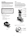
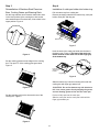
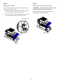
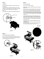
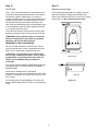
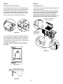
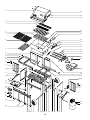
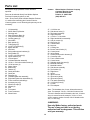
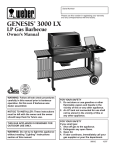
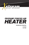
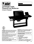
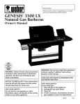
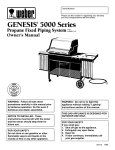
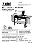
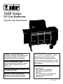
3400 Series LP Gas Barbecue Step-By-Step Instructions , , , ,,,, , , , ® ® E F WARNING: Follow all leak check procedures carefully in this manual prior to barbecue operation. Do this even though the barbecue is assembled. NOTICE TO INSTALLER: These instructions must be left with the owner and the owner should keep them for future use. THIS GAS APPLIANCE IS DESIGNED FOR OUTDOOR USE ONLY. WARNING: Do not try to light this appliance without reading "Lighting" instructions section of this manual. FOR YOUR SAFETY 1. Do not store or use gasoline or other flammable vapors and liquids in the vicinity of this or any other appliance. 2. An LP tank not connected for use shall not be stored in the vicinity of this or any other appliance. FOR YOUR SAFETY If you smell gas: 1. Shut off gas to the appliance. 2. Extinguish any open flame. 3. Open lid. 4. If odor continues, immediately call your gas supplier or your fire department. 63601 6/96 Step 2 Assembly Remove packaged parts Supplies needed Remove and unpackage glass door assemblies, warming rack, Weber Warm-Up Basket, 2 cooking grates, corrugated box (which contains cookbook and warranty card), 8 short stainless steel Flavorizer Bars and 5 long stainless steel Flavorizer Bars. Figure 2. You will need a soap and water solution to check for gas leaks. (See Step "Check for gas leaks.") Refer to exploded view if replacement parts are needed. Your LP tank is shipped empty for safety. After setting the LP fuel scale you will need to fill it. (See Step "Fill LP tank.") Note - Be sure no packaging material is left in the cooking box before reinstalling parts. Corrugated box containing glass doors While we give much attention to our products, unfortunately an occasional error may occur. If a part is missing, do not go back to the store. Call the Weber Customer Service Center toll free 1-800-446-1071 to receive immediate assistance. Have your owner’s manual and serial number of the barbecue available for reference. Warming basket Weber Warm-Up Basket Cooking grates Step 1 Short Stainless Steel Flavorizer Bars Removal of all tape Remove tape from the following locations: Long Stainless Steel Flavorizer Bars front and rear of side work tables swing tables swing table slide bars bottom tray beneath the cooking box bottom accessory trays Figure 2 Remove packaging material from the side burner. Figure 3. protective plastic on the stainless steel lid Figure 1 protective paper cap on the burner Figure 3 3 Step 3 Step 4 Reinstallation of Stainless Steel Flavorizer Bars, Cooking Grates and Warming Rack Installation of catch pan holder into bottom tray Pull out bottom tray from cooking box. Remove packaging material from bottom tray, catch pan holder, catch pan, and drip pan. Set the long stainless steel Flavorizer bars side to side in the lower position of the cooking box, then set the short stainless steel Flavorizer bars, front to back in the upper position. Figure 4. Bottom tray Figure 7 Hook the ends of the catch pan holder into the hole in the bottom tray. Figure 8. The front of the catch pan holder must be on the same side as the finger grip of the bottom tray. Figure 4 Set the cooking grates onto the ledges in the cooking box. The open "U" of the cooking grate goes down. Figure 5. Front of catch pan holder Finger grip Figure 8 Slide the bottom tray onto the mounting rails under the cooking box with finger grip toward you. CAUTION: Do not line bottom tray with aluminum foil. It can cause grease fires by trapping the grease and not allowing grease to flow into the catch pan. Figure 5 Set the warming rack into the slots at the rear of the cooking box. Figure 6. Put the foil drip pan into the catch pan. Slide the catch pan into the catch pan holder with its finger grip towards you. Figure 6 4 Step 5 Step 6 Removal of LP Tank Remove grill from lower packaging Note - You must remove tank and it's packaging before lifting grill out of lower carton. WARNING: Lifting the barbecue from the lower packaging requires at least two people. 1) Loosen tank lock wing nut and turn tank lock up out of the way. Tighten wing nut. Figure 9 (a). With two people lift straight up and over lower packaging and cardboard support. 2) Lift tank straight up. The cardboard sleeve will come with it, then remove the sleeve from the tank. Tank lock wing nut E F (a) Figure 10 Figure 9 5 Step 7 Step 9 Install Lid Set LP fuel scale Remove hinge pins and hair pin cotters from back of cooking box. You will need: LP tank (empty). Note - For accuracy, the fuel scale must be set with an empty tank. Set the lid in place. Align the hinges at the rear of the barbecue. Insert hinge pins from the outside. Insert hair pin cotters into the small holes in the hinge pins. Figure 11. We utilize various LP tank manufacturers. Some of the tanks we receive have differing top collar assemblies. (The top collar is the metal protective ring around the valve.) One series of tanks mounts with the valve facing front. The other tanks mount with the valve facing away from the fuel scale. These types of tanks are illustrated in Figure 13. Remove tape securing the thermometer into its holder. Hair pin cotter Loosen the tank lock wing nut. Tighten so the lock is held up out of the way. Figure 13 (a). Lift and hook the tank onto the fuel scale. With an empty LP tank, adjust the fuel scale setting to E with scale setting (top) wing nut. Figure 13 (b). Hinge pin CAUTION: Do not remove adjustment wing nut from tank scale. After adjusting tank scale, push tank down a couple of times to check that the tank scale is set on “E”. Scale setting wing nut (a) E Figure 11 F Step 8 Install Weber Warm-Up Basket Insert one end of the Weber Warm-Up Basket into the hole in the right end of the lid and the other end into the slot in the left end of the lid. Figure 12. E F (b) Figure 13 Figure 12 6 Step 10 Step 11 Fill LP tank Remove control panel Note - The LP tank manufacturer is responsible for the materials, workmanship and performance of the tank. If the tank has a defect, malfunctions, or you have a question regarding the tank, call the tank manufacturer's customer service center. The phone number is on the warning decal which is permanently attached to the tank. If the tank manufacturer has not resolved the issue to your satisfaction, then call Weber-Stephen Products Co., Customer Service Center. Pull the right hand swing table up. Stand to the right side of the barbecue. Slightly pull back both side burner locks. Slide the side burner out from the control panel. Figure 14. Do not disconnect the hose. To fill, take the LP tank to an RV center or look-up gaspropane in the phone book for other sources of LP gas. WARNING: We recommend that your LP tank be filled at an authorized LP gas dealer by a qualified attendant, who fills the tank by weight. IMPROPER FILLING IS DANGEROUS. Tell your LP dealer that this is a new LP tank. The air must be removed from a new LP tank before the initial filling. Your LP tank dealer is equipped to do this. CAUTION: If you exchange your LP tank, make sure you get a similar tank in return. Your LP tank is equipped with a quick-disconnect valve. Other LP tanks are not compatible with your barbecue connection. View from top The LP tank must be installed, transported and stored in an upright position. LP tank should not be dropped or handled roughly. Never store or transport the LP tank where temperatures can reach 125° Fahrenheit (too hot to hold by hand – for example: do not leave the LP tank in a car on a hot day). Side view Figure 14 For full instructions on safe handling of LP tanks, see Section "Safe handling tips for LP gas,” in the Operating Guide. 7 Remove the burner control knobs. Figure 15 (a). While standing at the right end of the barbecue, grasp the under the edge of the control panel at the control panel push-in buttons and slide along the frame toward you. Figure 15 (b). Lift off the control panel. Check that the igniter is secure in the frame brace and has not shifted out of the key hole. Figure 17. If it is loose, slide the igniter into the rear of the key hole. Carefully tighten the igniter lock nut with an adjustable wrench or pliers. (a) (a) Frame brace control panel push-in buttons (b) Keyhole in Igniter lock nut frame brace (b) (c) Figure 15 Step 12 Check that items are secured Note - Although the following items were factory assembled, check that they have not loosened during shipping and handling. Frame brace Remove the tape from the manifold bracket. Check that the bracket is securely hooked onto the frame brace and under the manifold at the center burner valve. Figure 16. Small part of keyhole in frame brace Figure 17 If it is loose lift the bracket, manifold and cooking box slightly as a unit and reposition onto the frame brace. Manifold Bracket Manifold Bracket Figure 16 8 Remove the tape from the hose and regulator. Check that the tank panel tabs are in their slots in the frame brace. Figure 18. Route the hose so it will not interfere with the scale indicator rod. Tank panel tabs The hose and regulator are connected in the following manner: Slide back the collar of the quick disconnect on the tank valve. Push the male fitting of the regulator into the quick disconnect, and maintain pressure. Slide the collar closed. Figure 21 (a). Figure 21 (b) shows the quick disconnect engaged and various components of the tank and regulator. Regulator vent hole should be at 3, 6, or 9 o'clock. It should not be pointed up. Figure 21 (c). (a) Figure 18 Collar Check that all the burner valves are off. Valves are shipped in the OFF position, but you should check to be sure. Put the knob on each valve. Check by pushing down and turning clockwise. If they do not turn, they are off. Proceed to the next step. Figure 19. Male fitting (b) Hose Tank valve Regulator Valve handwheel close clockwise Pressure relief valve Figure 19 Step 13 Tank Connect filled LP tank Regulator vent WARNING: Make sure that the LP tank valve is closed. Close by turning clockwise. Hook the LP tank onto the fuel scale. Loosen the tank lock wing nut. Swing the tank lock down. Tighten the wing nut. Figure 20. Quick disconnect engaged (c) Tank lock wing nut E Turn so regulator vent does not collect water F Figure 21 Figure 20 9 Step 14 WARNING: Do not ignite burners while leak checking. Check for gas leaks Check for leaks by wetting the connections with the soap and water solution and watching for bubbles. If bubbles form or if a bubble grows there is a leak. DANGER Do not use an open flame to check for gas leaks. Be sure there are no sparks or open flames in the area while you check for leaks. This will result in a fire or explosion which can cause serious bodily injury or death and damage to property. Check: a) Hose to manifold connection. Figure 24 (a). b) Regulator to tank connection. Figure 24 (b). c) Manifold to side burner hose connection. Figure 24 (c). WARNING: If there is a leak at connections a, b or c, retighten the fitting with a wrench and recheck for leaks with soap and water solution. WARNING: You should check for gas leaks every time you disconnect and reconnect a gas fitting. If a leak persists after retightening the fitting, turn OFF the gas. DO NOT OPERATE THE BARBECUE. Contact Weber-Stephen Customer Service. Note - All factory made connections have been thoroughly checked for gas leaks. The burners have been flame tested. As a safety precaution you should recheck all fittings for leaks before using your Weber Genesis Gas Barbecue. Shipping and handling may have loosened or damaged a gas fitting. d) Side burner hose to side burner connection. Figure 24 (d). e) Valves to manifold connections. Figure 24 (e). f) WARNING: Perform these leak checks even though the barbecue was assembled. Hose to regulator connection. Figure 24 (f). WARNING: If there is a leak at connections d, e or f, turn OFF the gas. DO NOT OPERATE THE BARBECUE. Contact Weber-Stephen Customer Service. You will need: a soap and water solution and a rag or brush to apply it. Note - Since some leaks test solutions, including soap and water, may be slightly corrosive, all connections should be rinsed with water after checking for leaks. When leak checks are complete, turn gas supply OFF at the source and rinse connections with water. (a) (b) Make sure side burner is OFF. Remove valve control knob and screws. Remove porcelain top. Figure 22. (c) Figure 22 To perform leak checks: open tank valve by turning the tank valve handwheel counterclockwise. Figure 23. (d) E (f) F (e) Figure 23 10 Figure 24 Step 15 Step 16 Put the control panel back on Install glass doors Set the control panel in place over both frame braces. (Hold the Crossover Ignition button up while setting the control panel in place.) Place your thumbs over the control panel push-in buttons, and push them into the frame brace until they snap into place. Figure 25 (a). You will need: one LH glass door assembly and two RH glass door assemblies. Start with the LH door assembly. Insert the long hinge pin at the top of the door into the plastic bushing in the underside of the left frame. Insert the bottom (short) hinge pin into the bushing in the frame connector. Repeat the procedure with the RH door assemblies. The glass doors latch on the frame connector. Figure 27. Push on the burner control knobs. Figure 25 (b). Bushing in underside and long hinge pin (b) (a) Bushing in frame connector and short hinge pin Figure 25 Pull the right hand swing table up. Stand to the right side of the barbecue. Slightly pull back both side burner locks. Slide the side burner toward the control panel. The locks will snap into the slots in the front and back of the side burner. Figure 26. Caution: Make sure both locks have snapped into place. Bushing in the underside Figure 27 View from top Side view Figure 26 11 1 43 44 ® ® 45 2 3 46 47 48 4 5 6 49 50 51 52 7 53 54 8 9 10 11 12 55 2 56 2 57 2 13 14 58 15-16 1 59 60 61-64 17 18-20 65-66 21 22 3 23 24 25 13 14 LH RH 26 RH W 27 E BE R 67 W 68 E BE R 28 29 30 31 32 33 34 35 36 37 12 38 38 39 40 41 42 Parts List Contact: All items are single quantities unless otherwise specified. Parts can be ordered directly from Weber-Stephen Products Company by phone or mail. Weber-Stephen Products Company Customer Service Center 250 South Hicks Road Palatine, IL 60067-6241 (800) 446-1071 Note - Do not return parts to Weber-Stephen Products Co. without first contacting the Customer Service Center by phone or mail. Returning the part may not be necessary. 1 2 3 4 5 6 7 8 9 10 11 12 13 14 15 16 17 18 19 20 21 22 23 24 25 26 27 28 29 30 31 32 33 34 35 36 37 38 39 40 41 42 43 44 45 46 47 48 49 50 51 52 53 54 55 56 57 58 59 60 61 62 63 64 65 66 67 68 Lid (assembly) Weber Warm-Up Basket Warming rack Short Flavorizer Bars (8) Long Flavorizer Bars (5) Cooking grates (2) Work table Back panels (3) Tubing plugs (4) 1/4-20 x 2 inch bolts (5) Spacer bracket Left frame Swing table support brackets (2) Swing tables (2) 1/4-20 x 1/2 inch bolts (6) Nylon washers (23) Left end panel Left hand slide bar assembly 10-24 x 1 3/4 inch machine screws (4) 10-24 hex nuts (4) Caster frame Bottom tray Casters (2) Catch pan holder Catch pan Drip pans (2) Left hand glass door assembly Right hand glass door assemblies (2) Frame connector w/bushings Accessory trays (2) Wheel hub caps (2) Wheels (2) Axle Front panel Frame connector Wheel frame 1/4-20 hex nut Side burner locks (2) Tank panel assembly Right end panel 1/4-20 x 1 1/2 inch bolt Right hand slide bar assembly Hair pin cotters (2) Hinge pins (2) Thermometer keps nut Cooking box Burner control knobs (3) Control panel Igniter button Control panel push-in buttons (2) Crossover tube Front or Back burner Center burner Stainless steel wing nuts (2) Manifold assembly Manifold bracket Side burner assembly Tool holders (3) Right frame Igniter Igniter lock nut Igniter wire (white) Igniter wire (black) Fuel scale (assembly) 1/4-20 wing nuts (2) LP tank Filler adapter Note - The hardware size of nuts, bolts and screws is given. For example "1/4-20 x 2 inch bolt" means a bolt 1/4 inch in diameter with 20 threads to the inch, 2 inches long. On a small screw for example, "6-32 x 1/2 inch screw" means a number 6 screw, with 32 threads to the inch, 1/2 inch long. WARNING: Use only Weber factory authorized parts. The use of any part that is not factory authorized can be dangerous. This will also void your warranty. 13 A FINAL WORD OF THANKS you for choosing a Weber Barbecue. TOurhankfamily here at Weber has worked hard to produce the highest quality products for your satisfaction. While we give much attention to our products, an occasional error may occur. Our knowledgeable Customer Service staff is prepared to help you with any problems with parts or assembly. Call our toll free number 1-800-446-1071. For quicker service, please have your owner’s manual available for reference. We also welcome any comments or suggestions you might have regarding our products. We wish your family the best in outdoor cooking enjoyment. Weber-Stephen Products Company Customer Service Center 200 East Daniels Road Palatine, Illinois 60067-6266