1
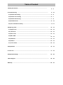
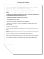
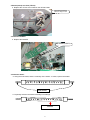
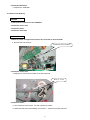
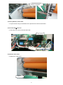
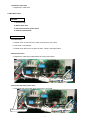
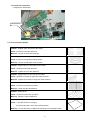
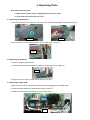
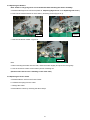
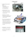
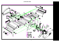
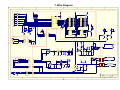
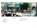
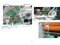
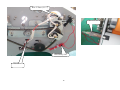
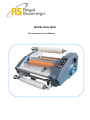
MODEL:RSH-380SL
Roll Laminator Service Manual
Table of Content
1.Safety Precautions ………………………………………………………………………
3 ~ 3
2.Troubleshooting ……………………………………………………………………………
4 ~ 10
2.1) Rollers Not Heating ………………………………………………………………………… 4 ~ 6
2.2) Rollers Over Heating …………………………………………………………………………6 ~ 7
2.3) Rollers Not Running ………………………………………………………………………… 7 ~ 9
2.4) No Main Power …………………………………………………………………………………9 ~ 10
2.5) Poor Lamination Quality …………………………………………………………………… 11 ~ 11
3.Replacing Parts ………………………………………………………………………………
12 ~ 14
3.1) Right Cover ……………………………………………………………………………………12 ~ 12
3.2) Left Cover
…………………………………………………………………………………… 13 ~ 13
3.3) Rear Cover ……………………………………………………………………………………13 ~ 13
3.4) Main PCB ………………………………………………………………………………………13 ~ 13
3.5) Sub PCB ……………………………………………………………………………………… 13 ~ 13
3.6) Heaters …………………………………………………………………………………………13 ~ 14
3.7) Cross Cutter ……………………………………………………………………………………14 ~ 14
4.Adjustments ……………………………………………………………………………………
15 ~ 16
5. Parts List …………………………………………………………………………………………
17 ~ 19
6.Exploded Drawings ………………………………………………………………………
20 ~ 25
7.Wire Diagram …………………………………………………………………………………
26 ~ 29
8.Backup ………………………………………………………………………………………………30 ~ 33
1. Safety Precautions
Failure to comply any of the following safety procedures could result in serious injury.
Please read the instructions carefully and keep for future reference.
1. Only a licensed electrician should install wiring and outlet for the laminator.
2. Ensure the unit is plugged into a properly grounded outlet with the correct
voltage.
3. Keep hands and clothing(ie.Neckties)away from rollers. The rollers are pinch points that
can trap body parts or clothing and cause serious injury .
Safety Precaution
4. Keep flammable and wet objects away from the machine .
5. Place machine on a level surface.
6. Avoid excessive sunlight, humidity and extreme temperatures.
7. Ensure the unit is turned off, cooled ,and unplugged from the outlet prior to moving
and/or repairing.
8. Keep out of reach of children.
9. Only Royal Sovereign authorized maintenance and service technicians should make
repairs.
10. Do not attempt to laminate items that exceed total recommended material thickness for
the unit.
11. When cleaning the machine, don't use flammable sprays or materials.
12. Do not touch the rollers when they are hot or place foreign objects inside the machine.
13. Do not cover the surface of the machine until the machine has completely cooled.
1
2. Troubleshooting
Note: While repairing:
a.
Make sure the power plug is unplugged from the power outlet.
b.
Open both side covers and rear cover.
c.
Be sure to follow the steps below in order.
2.1 Rollers Not Heating
CAUSES:
1. Improper laminating mode.
2. Heating wire is not connected to the main PCB.
3. Blown (burnt) upper and/or lower wire fuse (T/Fuse).
4. Defective Bi-Metal.
5. Defective heater.
6. Defective Main PCB.
MEASURE
1. Heating wire is not connected to the main PCB.
a. Connect the upper and lower heating wires to the main PCB.
Wire-Heater
Wire-Heater
2
2. Blown (burnt) wire fuse (T/Fuse).
a. Replace the T/Fuse wire located on the left-hand side.
Wire-Temp. Fuse
3. Defective Bi-Metal.
a. Replace the Bi-Metal
Bi-metal (135℃)
4. Defective heater.
a. Using the multi-meter, test the continuity of the heater. If it fails, replace the heater.
Multi-meter
b. Physically examine the heater assembly for breakage.
Broken
3
5. Defective Main PCB.
a. Replace the PCB Main.
2.2 Rollers Over Heating
CAUSES
1. Heat sensor is reversed on the PCB Main.
2. Defective T/Fuse wire.
3. Defective heater.
4. Defective main PCB.
MEASURES
1. Wires for lower and upper heat sensors are reversed on the main PCB.
a. Reverse the heat sensors.
Connector-Wire Sensor
2. Defective T/Fuse wire.
a. Replace the T/Fuse wire located on the left-hand side.
Wire-T / Fuse
3. Defective heater.
a. Test continuity of the heater. If it fails, replace the heater.
b. Glass tube that surrounds heating coil is broken – replace the heating element.
4
4. Defective Main PCB.
a. Replace the PCB Main.
2.3 Rollers Not Running
CAUSES
1. No power to the unit.
2. The main switch is close.
3. Opened safety cover.
4. Film is jammed on the rollers.
5. Disconnected motor wire.
6. Defective main motor.
7. Defective main PCB.
MEASURES
1. No power to the unit.
a. Make sure the power plug is connected to the proper source of outlet
2. The main switch is close.
Main Switch
3. Opened safety cover.
a. Close the safety cover and double check to insure that the safety cover switch
is engaged.
Note: By closing the safety cover, it engages the safety cover switch.
5
Switch is engaged
4. Film is jammed on the rollers.
a. Un-jam the film using a combination of the pressure lever and reverse button.
5. Disconnected motor wire.
a. Check the motor wire connection with PCB.
Wire-motor
6. Defective main motor.
a. Replace the main motor.
Motor
6
7. Defective main PCB.
a. Replace the main PCB.
2.4 No Main Power
CAUSES
1. No electricity.
2. Blown main fuse.
3. Disconnected main power wires.
4. Defective transformer.
MEASURES
1. No Electricity.
a. Double check to insure that you have electricity from your outlet.
b. Check the circuit breaker.
c. Double check that source of power is 220V, 15Amp, and single phase.
2. Blown main fuse.
a. Replace the main fuse located above the main power switch.
Main Fuse
3. Disconnected main power wires.
a. Check that the main power wires are properly connected.
Main Power Wires
7
4. Transformer is defective
a. Replace the transformer.
Transformer
2.5 Poor Lamination Quality
Problem: Straight wave lines across the output.
Cause: Excessive front roller pressure.
Measure: Loosen the front roller pressure.
Problem: Concave waves in the lamination.
Cause: Excessive rear (pulling) roller pressure.
Measure: Loosen the rear back roller pressure.
Problem: Angled waves on both sides of the output.
Cause: Insufficient rear roller pressure.
Measure: Tighten the rear roller pressure.
Problem: Angled waves on one side of the output.
Cause: Insufficient rear left (or right) side roller pressure.
Measure: Tighten the rear left (or right) side roller pressure.
Problem: Straight waves in the output.
Cause: Excessive heat at the nip rollers.
Measure: Lower the roller temperature.
Problem: Wake waves.
Cause: Insufficient heat at the nip rollers.
Measure: Raise the roller temperature.
Problem: Curling.
Cause: 1.The film tension is very tight;
2.The decurling bar is not in the working location.
Measure: 1.Loose the tension;2.Adjust the decurling bar to working location.
8
3. Replacing Parts
Note: While replacing parts:
a. Make sure the power plug is unplugged from the power outlet.
b. Open both side covers and rear cover.
3.1 Replacing the Right Cover.
a. Take out the pressure lever (Figure 1) and four cover screws using Phillips screw driver (Figure 2).
Figure 1
Figure
b. Pull out the male control panel connector from the Sub-PCB( Figure 3).
Figure
3.2 Replacing the Sub-PCB
a. Refer to “Replacing Right Cover”.
c. Loosen two screws from Sub-PCB , installed on to new Right Cover (Figure 4).
Figure
d. Follow the reverse order to assemble the Right Cover back.
3.3 Replacing the Main PCB
a. Remove the rear cover and label all the wires before unplugging from the Main PCB.
b. Detach the Main PCB from 6 white plastic holders ( Figure 7).
c. Replace the board with new PCB and connect all the wires.
Figure
9
3.4 Replacing the Heaters
Note: Cotton or surgical gloves are recommended while handling the heater assembly.
a. Disassemble Right and Left Covers (Refer to “Replacing Right Cover” and “Replacing Left Cover”).
b. Take out the heater brackets on each side by loosening screws (Figure 8, 9).
Figure9
Figure8
c. Take out the broken heater. Figure 10
Figure 1
Note:
a. When inserting the heater into the roller, rotate the heater slightly and push the rod in gently.
b. Use an air blower to blow out the broken pieces of heating rod.
(Please ensure that no one is standing on the other side.)
3.5 Replacing the Cross Cutter
a. Disassemble the nut from the Frame-Cutter.
b. Unfasten the spring from the cutter.
c. Change the Cutter.
d. Assemble the Cutter by reversing the above steps.
10
4. Adjustments
C.W
C.C.W
.2 Adjusting front and rear rollers
Pressure
• Use Screwdriver
to adjust the roller pressure:
C.W – Increase pressure.
C.C.W – Decrease pressure.
1.Using Push-Pull Scale , measure
3 spots as shown on Figure B &C:
Figure A
Front roller should be 5~6 and back
rollers should be 6~8.
2.Checking for over all tension –
when the machine is running, check that
the top and the bottom films are fed in
without any wrinkles.
3.Pressure mark checking (Heat Line) –
stop the machine for 30 seconds to
create a heat line. Then check to see if
you have two even parallel lines from
one end to other. Note: A narrow parallel
lines indicate that it has less pressure
Figure B
at that point.
4.Laminating Test – Laminate samples
with different thickness of substrates.
5.Check above steps 2 through 4 with
3mil & 5mil films.
Figure C
11
5.PART LIST
No.
Part No.
Part Name
Spec.
1
021LR0001A
COVER-L
ABS PA-765 UL94 V-0 PANTON 431
2
125LR4001A
HANDLE-TENSION
S45C Cu+Ni+Cr
3
138LR4012A
SPRING-TENSION
SWP Ф3.2
4
12200X022A
BEARING-RADIAL
15*28
5
141LR4033A
PLATE-PRESSURE,PULL
SPCC 3.0T
6
138LR4015A
SPRING-PRESSURE
SWP Ф2
7
141LR4032A
PLATE-PRESSDURE,LAMI
SPCC 3.0T
8
141LR4035A
PLATE-DU BUSH
SECC T=2.0
9
141LR4019A
BRACKET-HEATER,UP
SPCC 1.6T
10
36400X014B
MICRO SWITCH
AC 250V/5A 50-60HZ
11
141LR4054A
BRACKET-LIMIT SWITCH
SPCC 2.0T
12
147LR4013A
STOPPER-HEATER,UP
SILICONE
13
141LR4020A
BRACKET-HEATER,LOW
SPCC 1.6T
14
141LR3039A
PLATE-PRESSURE,L
SPCC 3.0T
15
021LR4001A
LAMIT-SWITCH COVER
PP
16
122LR4044A
BUSH-ROLLER LAMI,UP
FTG70 CU 3-35
17
122LR4046A
BUSH-ROLLER PULL,UP
FTG70 CU 3-35
18
111LR4024A
BOLT-GUIDE
S45C
19
124LR4005A
CAM
S45C
20
122LR4050A
BUSH-ROLLER LAMI,LO
FTG70 CU 3-35
21
122LR4047A
BUSH-ROLLER PULL,LO
FTG70Cu3-35
22
136LR4001X
CHAIN
RS#25 P6.35 98节
23
013LR3142A
FRAME-L
SPCC 3.0T
24
147LR4002A
PAD-TENSION
LEATER 1.5T
25
140LR4036A
HOLDER-SHAFT,FILM
S45C Cu+Ni+Cr
26
120LR4002M
SHAFT-FILM
S45C N19
27
ASMLR1339A
ASSY-AUTO GRIP CORE 2"
RSH-380SL
27-1
ASMLR1339B
ASM-AUTO GRIP CORE3"
RSH-380SL
27-2
124LR4006A
CORE-24
AL 6063
28
RIV05018E8
BRINDER RIVET
AL φ5*18
29
12200X029A
DU-BUSH
FLANGE Ф10*10
30
026LR4006A
FOOT
NBR 160g
31
141LR4064A
BRACKET-TABLE
SPCC 2.2T
32
013LR3146A
FRAME-STAND
25*25*2.0 SQUARE TUBE
33
023LR4002A
KNOB-BOLT GUIDE
PHENOL BLK
34
145LR3002A
GUIDE-DOCUMENT
ABS PA-765 UL94V-0 431C
12
Remark
35
141LR4043A
FRONT TABLE SAFETY LEVER
SPCC 1.5T
36
013LR4004A
SAFETY FRAME
SPCC
37
021LR3024A
SAFETY-COVER
PC 3.0T
38
014LR3001B
TABLE-FRONT
AL6063
39
133LR3001A
ROLLER-LAMI
STPG ORG
40
223LR3001H
HEATER ASS'Y
FCHW1 81Ω EU,KR,CH,EU(N),BR
40-1
223LR3001J
HEATER ASS'Y
FCHW1 96Ω AU,UK
40-2
223LR3001E
HEATER ASS'Y
FCHW1 24Ω CUL
40-3
223LR3001D
HEATER ASS'Y
FCHW1 20.2Ω TW
40-4
223LR3001F
HEATER ASS'Y
FCHW1 16.7Ω JOL,JAP
41
140LR4003A
HOLDER-SAFETY COVER
S45C
42
111LR4018A
SCREW-H
SWRH MFZN-Y
43
131LR4027A
SPROCKET-MOTOR
S45 24Z
44
210004002A
MOTOR-MAIN
DC 24V
45
131LR4017A
SPROCKET-LAMI
FTG70Cu3-35 28z
46
120LR3031B
SHAFT-CAM
S45C Cu+Ni+Cr
47
013LR3143A
PLATE-MIDDLE
SPCC 0.5T
48
015LR2010A
BAR-IDLE
S45C Φ20
49
015LR3011C
IDLE-BAR
S45C Cu+Ni+Cr
50
015LR3012C
SHAFT-DECURLING
S45C Cr
51
131LR4018A
SPROCKET PULL
FTG70Cu3-35 20z
52
133LR3002A
ROLLER-PULL
S45C GRY
53
013LR3144A
REAR-COVER
SPCC 0.5T
54
013LR3145A
TABLE-CUTTER
SPCC 2.0T
55
013LR3002H
FRAME-CUTTER
AL6063
56
021CR3001A
KNOB-CUTTER,C
ABS PA-765 UL94 V-0 PANTON 431C
57
140LR3001A
HOLDER-CUTTER,C
ABS PA-765 UL94 V-0 PANTON 431C
58
213LR4001A
CUTTER-CROSS
STS420 J2 1T
59
34000S011A
POWER TRANSFORMER
AC110-120V,220-240V/50-60HZ
60
141LR3038A
PLATE-PRESSURE,R
SPCC 3.0T
61
144LR4001B
CLAMPER-LEVER
S45C Cu+Ni+Cr
62
023LR4010A
KNOB LEVER
NYLON BLK
63
125LR4003B
LEVER-PRESSURE
S45C Cu+Ni+Cr
64
120LR4009B
SHAFT-COVER SAFETY
S45C
65
350LR3042A
PCB MAIN ASM
ROHS
66
032LR3029A
SHEET-FUNCTION
PC 0.75T
66-1
032LR3029C
SHEET-FUNCTION
PC 0.75T
67
023LR3007B
BUTTON-FUNC
SILICON
13
68
350LR3043A
PCB-SUB ASSY
FR-4
69
36600X001A
FUSE-BLOCK
FB66 LITTLE FUSE TRIAD INC
70
32500X0008
FUSE-MAIN
65TS AC250V 10A EU,AU,KR,CH,UK,EU(N),BR
70-1
32500X0005
FUSE-MAIN
65TS AC250V 20A TW,CUL,JOL,JAP
71
021LR3018A
COVER-R
ABS PA-765 UL94 V-0 PANTON 431
72
138LR4001A
SPRING-CUTTER CROSS
SWRH Φ0.3
73
KPS03012D2
KEY PLAIN
3*3*12 SUS27
74
138LR4018A
SPRING-LEVER
SUS 304-WPB
75
12200X027A
DU-BUSH
FLANGE Ф25*10
76
12200X028A
DU-BUSH
FLANGE Ф25*20
77
111LR4006A
BOLT-GUIDE
S45C SNC3 4*22.5
78
12200X030A
DU-BUSH
FLANGE Ф10*20
79
013LR3141A
FRAME-R
SPCC 3.0T
80
36400X002B
SWITCH-MAIN
8216 B/R I/O SIGNAL-LUX SPA
81
013LR2012G
FRAME-SENSOR
AL6063
82
033LP4016A
MICA-WASHER
Φ4*Φ11 T=0.5
83
12200X032A
DU-BUSH
FLANGE Ф12*10
84
12200X040A
DU-BUSH
φ6*8 FLANGE
85
363LR4013A
BIMETAL THERMOSTAL
135℃ 15A
86
141LP4018A
BRACKET-FUSE
EGI T=1
87
147CR4003A
SILICON RUBBER
SILICON Φ7*160
88
23300X001A
BUSHING-CORD,EU
7NR32 DONG-A
89
111LR4004A
BOLT-CORE
S45C Φ15*42
90
ASMLR2023A
ASM SENSOR
RSH-380SL
91
381LR4020B
WIRE-FUSE,EU
UL1015 AWG#14
92
381LR4052A
WIRE-MOTOR
UL1007 AWG#20 BLK RED
93
381LR4115A
WIRE-MAIN
UL2464 AWG#24,BLE
94
381LR4062B
WIRE-HEATER
UL1015 AWG#16 WHITE
95
381LR4063A
WIRE-TEMP FUSE
SF133E,AC250V 15A 133℃ UL1015 AWG#14
96
381LR4049A
WIRE-BIMETAL
UL1015 AWG#18, WHT
97
381LR4114A
WIRE-HEATER LOW
UL1015 AWG#16, WHT
98
381LR4051A
WIRE-HEATER LINK
UL1015 AWG#18, WHT
99
380LR4001A
POWER CORD
EU AC250V 15A 1.8M
99-1
380LR4003A
POWER CORD
AU AC250V 15A 1.8M
99-2
380CR4007A
POWER CORD
UK AC250V 10A 1.8M
99-3
380LR4001B
POWER CORD
KR AC250V 15A 1.8M
99-4
380CR4003A
POWER CORD
JAP AC125V 15A 1.8M
99-5
380CR4004A
POWER CORD
CUL AC125V 15A 1.8M
14
6.EXPLODE VIEW
24
25
27
26
1
2
3
29
28
4
56
55
54
6
6
5
57
86
6
23
9
6
51
7
83
53
52
48
8
21
78
72
29
17
50
52
49
12
16
18
11
58
31
84
19
18
90
15
10
81
12
13
41
14
31
44
43
83
18
76
47
2
20
3
46
4
45
73
84
42
32
41
31
31
75
41
31
39
80
31
40
22
79
36
30
40
37
83
39
32
35
6
33
6
77
48
30
42
5
34
31
31
6
41
62
41
6
64
82
83
7
38
17
78
65
41
36
64
63
82
24
21
16
60
64
76
25
82
18
26
18 19
31
64
29
31
82
9
18
61
20
59
66
73
70
71
75
27
69
32
74
13
89
381LR4020B
91
12
12
67
381LR4052A 92
85
68
381LR4115A 93
29
87
31
30
31
28
381LR4062B 94
381LR4063A 95
381LR4049A 96
J2
UP
LOW
J1
381LR4114A 97
381LR4051A 98
30
88
380LR4001A 99
15
No.
1
2
3
4
5
6
7
8
9
10
11
12
13
14
15
16
17
18
19
20
21
22
23
24
25
26
27
27-1
27-2
28
29
30
31
32
33
34
35
36
37
38
39
40
40-1
40-2
40-3
40-4
41
42
43
44
45
46
47
48
49
50
51
52
53
54
55
56
57
58
59
60
61
62
63
64
65
66
66-1
67
68
69
70
70-1
71
72
73
74
75
76
77
78
79
80
81
82
83
84
85
86
87
88
89
90
91
92
93
94
95
96
97
98
99
99-1
99-2
99-3
99-4
99-5
Part No.
021LR0001A
125LR4001A
138LR4012A
12200X022A
141LR4033A
138LR4015A
141LR4032A
141LR4035A
141LR4019A
36400X014B
141LR4054A
147LR4013A
141LR4020A
141LR3039A
021LR4001A
122LR4044A
122LR4046A
111LR4024A
124LR4005A
122LR4050A
122LR4047A
136LR4001X
013LR3142A
147LR4002A
140LR4036A
120LR4002M
ASMLR1339A
ASMLR1339B
124LR4006A
RIV05018E8
12200X029A
026LR4006A
141LR4064A
013LR3146A
023LR4002A
145LR3002A
141LR4043A
013LR4004A
021LR3024A
014LR3001B
133LR3001A
223LR3001H
223LR3001J
223LR3001E
223LR3001D
223LR3001F
140LR4003A
111LR4018A
131LR4027A
210004002A
131LR4017A
120LR3031B
013LR3143A
015LR2010A
015LR3011C
015LR3012C
131LR4018A
133LR3002A
013LR3144A
013LR3145A
013LR3002H
021CR3001A
140LR3001A
213LR4001A
34000S011A
141LR3038A
144LR4001B
023LR4010A
125LR4003B
120LR4009B
350LR3042A
032LR3029A
032LR3029C
023LR3007B
350LR3043A
36600X001A
32500X0008
32500X0005
021LR3018A
138LR4001A
KPS03012D2
138LR4018A
12200X027A
12200X028A
111LR4006A
12200X030A
013LR3141A
36400X002B
013LR2012G
033LP4016A
12200X032A
12200X040A
363LR4013A
141LP4018A
147CR4003A
23300X001A
111LR4004A
ASMLR2023A
381LR4020B
381LR4052A
381LR4115A
381LR4062B
381LR4063A
381LR4049A
381LR4114A
381LR4051A
380LR4001A
380LR4003A
380CR4007A
380LR4001B
380CR4003A
380CR4004A
Part Name
COVER-L
HANDLE-TENSION
SPRING-TENSION
BEARING-RADIAL
PLATE-PRESSURE,PULL
SPRING-PRESSURE
PLATE-PRESSDURE,LAMI
PLATE-DU BUSH
BRACKET-HEATER,UP
MICRO SWITCH
BRACKET-LIMIT SWITCH
STOPPER-HEATER,UP
BRACKET-HEATER,LOW
PLATE-PRESSURE,L
LAMIT-SWITCH COVER
BUSH-ROLLER LAMI,UP
BUSH-ROLLER PULL,UP
BOLT-GUIDE
CAM
BUSH-ROLLER LAMI,LO
BUSH-ROLLER PULL,LO
CHAIN
FRAME-L
PAD-TENSION
HOLDER-SHAFT,FILM
SHAFT-FILM
ASSY-AUTO GRIP CORE 2"
ASM-AUTO GRIP CORE3"
CORE-24
BRINDER RIVET
DU-BUSH
FOOT
BRACKET-TABLE
FRAME-STAND
KNOB-BOLT GUIDE
GUIDE-DOCUMENT
FRONT TABLE SAFETY LEVER
SAFETY FRAME
SAFETY-COVER
TABLE-FRONT
ROLLER-LAMI
HEATER ASS'Y
HEATER ASS'Y
HEATER ASS'Y
HEATER ASS'Y
HEATER ASS'Y
HOLDER-SAFETY COVER
SCREW-H
SPROCKET-MOTOR
MOTOR-MAIN
SPROCKET-LAMI
SHAFT-CAM
PLATE-MIDDLE
BAR-IDLE
IDLE-BAR
SHAFT-DECURLING
SPROCKET PULL
ROLLER-PULL
REAR-COVER
TABLE-CUTTER
FRAME-CUTTER
KNOB-CUTTER,C
HOLDER-CUTTER,C
CUTTER-CROSS
POWER TRANSFORMER
PLATE-PRESSURE,R
CLAMPER-LEVER
KNOB LEVER
LEVER-PRESSURE
SHAFT-COVER SAFETY
PCB MAIN ASM
SHEET-FUNCTION
SHEET-FUNCTION
BUTTON-FUNC
PCB-SUB ASSY
FUSE-BLOCK
FUSE-MAIN
FUSE-MAIN
COVER-R
SPRING-CUTTER CROSS
KEY PLAIN
SPRING-LEVER
DU-BUSH
DU-BUSH
BOLT-GUIDE
DU-BUSH
FRAME-R
SWITCH-MAIN
FRAME-SENSOR
MICA-WASHER
DU-BUSH
DU-BUSH
BIMETAL THERMOSTAL
BRACKET-FUSE
SILICON RUBBER
BUSHING-CORD,EU
BOLT-CORE
ASM SENSOR
WIRE-FUSE,EU
WIRE-MOTOR
WIRE-MAIN
WIRE-HEATER
WIRE-TEMP FUSE
WIRE-BIMETAL
WIRE-HEATER LOW
WIRE-HEATER LINK
POWER CORD
POWER CORD
POWER CORD
POWER CORD
POWER CORD
POWER CORD
7. Wire Diagram
1
2
3
4
5
VCC_5V
VCC_5V
CA RB ON S/ W
6
7
VCC_5V
8
VCC_5V
SW1
U101
PIC16C72
C106
3.3/50V
TEMP_UP SW
SW4
12
13
11
28
HEATER
TEMP_DOWN SW
PWMOUT
HEATER2
REVRELAY
SW5
RC1/T1OSI
RC2/CCP1
RC0/T1OSO/T1CKI
RB7
REV_SW
15
16
17
18
3
5
14
4
6
SPEED _UP SW
SW6
SPEED _DOWN SW
STOP_SW
TEMP_UP SW
TEMP_DOWN SW
REVSW
SW7
STOP SW
RUN_SW
RU N SW
RU N LED
HEATER2 LED
R103
330
LED3
6
5
QG2
6
5
8
7
QF2
8
7
QE1
10
9
QE2
10
9
SER2
BUZZER
QD 1
12
11
QD2
12
11
QC 1
14
13
QC2
14
13
QB1
16
15
QB2
16
15
QA1
18
17
QA2
18
17
20
19
20
19
SRCLK2
H/Display Com
R102 1M
XTAL101
8Mhz
RA0/AN0
GND_EARTH
470/25V
C107
2
2
VCC_5V
U102
74LS595
9
C105
3
VCC_5V
CN6
1
2
3
4
5
6
6
5
4
3
2
1
PWM- OUT
REV-RELAY
SRCLR
QH
QG
QF
QE
QD
QC
QB
QA
SER
SRCLK
RCLK
G
10
14
11
12
9
7
6
5
4
3
2
1
15
SER1
SRCLK1
RCLK1
13
QH
SRCLR
QH
QG
QF
QE
QD
QC
QB
QA
SER
SRCLK
RCLK
10
14
11
12
12V
SRCLK2
D1
BUZZER1
RCLK2
D2
1
2
13
G
Q2
C102M
1
REV
HEATER
HEATER2
SENS_ASS'Y
利寇急 SENSOR ASS'Y
CNN102
SMH025-05
vcc
gnd
1
2
1N4007
HEATER2
C
Q3
C102
1
R12
3K
CN102
SMW025-05
1
2
3
4
5
sensor_in
s_out
24V
1N4007
Q101
C102M
SER2
3
C
QH
U103
74LS595
F
2
1
D
M
1
H
C
_
2
Y
R
7
6
5
4
3
2
1
15
104
BZ1
BUZZER
R101
330
GND_EARTH
VCC_5V
CN101
3
VCC_5V
VCC_5V
330
LED4
Q104
C102M
1
D
F
2
1
D
M
2
H
C
1
Y
R
1
3
QF1
QG1
SER1
MA IN -S UB
Q103
C102M
RA103
330R 10P
1
2
LED2
LA102
LDQ-N51R
4
2
LED1
2
TEMP SEN SOR
R103
2
QH2
RC LK1
10
OSC2/CLKOUT
RA102
330R 10P
3
RC LK2
SRCLK1
9
OSC1/CLKIN
1
4
3
VCC_5V
RC4/SDI/SDA
RC5/SDO
RC6
RC7
RA1/AN1
RA3/AN3/VREF
RC3/SCK/SCL
RA2/AN2
RA4/TOCKI
21
22
23
24
25
26
27
7
RB0/INT
RB1
RB2
RB3
RB4
RB5
RB6
RA5/AN4/SS
LA101
LDQ-N51G
2
QH 1
2
MCLR/Vpp
SW3
D
Q102
C102M
1
H/Display Com
1
3
10K x 10
SPEED_DOWN SW
3
RA101
SW2
2
R104
10K
SPEED_UP SW
1
2
3
4
5
5v
R103
10K
C104
104
24V
24V
24V
SE NS OR
R6
R7
1K 1w
680 2w
HEATER
Q4
A1271
R4
VCC_5V
330
-
R5
HS?
HS-529
+
CN7
YW396-03V
FUSE1
1
2
3
D3
4
1N4148
2
3
R9
G
VO
HS?
HS-529
3
Q1
IRF830
220 1w
PC817
1
B
C4
1000/50V
C5
470/25V
C6
104
C101
104
C102
104
DC
1
2
3
DC?
MOTOR DC
-
RY1A
FF/REV Motor
CH2-MD12F
2
1
+
VI
CNN7
YH396-03V
470 1w
U4
U2
KA7805/1A
BD2
DB105G
D4
FR105
T 6.3AL 250V
PWM
C103
104
R8
2k
R10
4.7K
D5
B
FR105
ZD1
1W 15V
24v_gnd
SK2
104 120з
D6
CNN2
YH396-03
1
2
3
-
U1
R6
+
KA7824
VI
75 2w
C7
104
1
2
3
C1
100nF/275V MKP
C2
4700/100V
24V
R1
330
C8
470/50V
C3
104
C9
104
1
CNN5
MG610599
2
2
1
1
HEATER ASS'Y
TAC1
R2
100
BTA24-600C
SK1
104 120з
bimetal 70∩
UP Heater
U3
MOC3043
A
2
AC POWER S/W
FUSE1
T 15A 250V
AC_in
1
HEATER2 ASS'Y
bimetal 70∩
VO
CN1
BR-1103C02P
4
A
4
CN5
MG640598
Q5
PNP
CN2
YW396-03AV
P/ T IN PUT
2
RY2A
CH1-MD12F
P/ T OU TPU T
BD1
BR-106
POWER TRANSFORMER
TAC1
HS-501
1N4007
CNN4
MG610599
2
5
3
P/ T OU TPU T
CN4
MG640598
6
5
4
3
2
1
1
AC24V
HS?
HS-529
CN3
5
4
3
2
1
G
CNN3
AC13V
DOWN HEATER
R3
10K 1/2W
1
2
Title
AC I NP UT
Size
Number
Revision
A2
Date:
File:
1
2
3
4
5
16
6
7
6-Mar-2009
Sheet of
D:\PROGRAM FILES\EXAMPLES\RSL-382S CI\RSL-382S
Drawn By: CI.DDB
8
5
2
8
7
4
1
3
6
<Connect part>
1. Wire Main.
6. Wire Power Transformer In
2. Wire Power
7. Wires Power Transformer Output
3. Wire Heater,up
8. Wire Fuse
4. Wire Heater,low
5. Motor wires
17
SUB PCB
Bimetal(135℃)
Wire Sensor
Fuse Main
Power Cord
Wire Bimetal
Motor
Wire Lo Heater
Wire Up Heater
18
Wire T/Fuse (133℃)
Micro Switch
Wire Safety S/W
Wire Motor
19