1
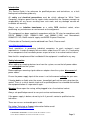
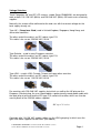
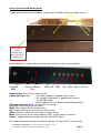
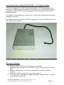
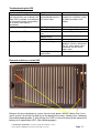
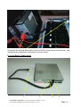
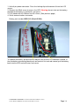
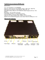
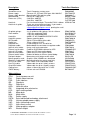
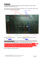
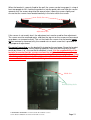
Torch Computers
EN069K Series
Service Guide
46 and 52 inch LCD screen
with integrated computer
50 South Street, Comberton, Cambridge CB3 7DZ
Telephone 01223 263818 Fax 01223 264118
Email: [email protected]; Website: http://www.torchcomputers.co.uk
Service Guide for EN069K Series
46 & 52 inch LCD screen
with built-in computer
Contents
Introduction
page 3
Safety and Warning information
page 3
Voltage Selection
UK, Singapore, Hong Kong
Europe
USA, Canada, Taiwan
page 4
Cable Access to the screen
page 6
Screen Controls and Buttons
page 8
Powering the screen on/off
page 9
Computer Interfaces
page 10
Uninterruptible Power Supply (IUPS)
page 11
Troubleshooting guide (IUPS) and removal
page 12
Fuse and Battery replacement (IUPS)
page 13
SoundFoCS Computer EN0039K series
page 15
Internal Components
page 16
Troubleshooting guide Computer and Screen
page 17
Speaker Audio Orientation Switch (Option)
page 19
Wall mounting
page 20
P:\WINWORD\P:\WINWORD\Torch Service Guide 46 and 52inch screens\
Service Guide for EN069K series 46 & 52 inch LCD screen.doc
Page 2
Introduction
This Service Guide is for reference for qualified persons and technicians, as a fault
finding and rectification guide only.
All safety and electrical precautions must be strictly adhered to. While Torch
Computers Ltd gives permission for repairs to be carried out, the Company accepts no
responsibility for any losses resulting from such work, and any damage caused will
invalidate our warranty.
Always use an isolation transformer or a safety RCD electrical socket, when
performing any maintenance or service work on the equipment.
This equipment has been supplied in accordance with the CE rules for compliance with
BS-EN 500081-1:1992, 500081-2:1992, and 500082-1:1992 and Amendment
93/68/ECC LVD, RoHS material supply and WEEE Disposal Directives.
A Declaration of Conformity can be obtained from Torch, Please email:
[email protected]
Torch specialises in producing individual computers to each customer's exact
requirements. In order to comply with our duties under these CE rules it is Torch policy
to use components that have been proven as part of a test in an authorised test house.
Note that this compliance will be invalidated if the equipment is modified in any way.
Safety Information
When adding or removing devices to or from the system, ensure that all power cables
are unplugged from the system.
Before adding or removing signal cables or adapters from the system, disconnect all
power cables.
Ensure the power supply input of the screen is set to the correct voltage for your area.
If foreign bodies or fluids enter the screen, immediately pull out the mains plug from the
socket. There is a risk of electric shock until a qualified person has checked and verified
the equipment before it is operated it again.
Warning: Never open the casing, while plugged in to a live electrical socket.
Always ask qualified personnel to carry out service maintenance jobs.
If the power supply is broken, do not try to fix it yourself, contact a qualified service
technician.
There are no user serviceable parts inside.
For further Technical or Support information Advice email:
[email protected]
P:\WINWORD\P:\WINWORD\Torch Service Guide 46 and 52inch screens\
Service Guide for EN069K series 46 & 52 inch LCD screen.doc
Page 3
Voltage Selection
Torch Computers 46” and 52” LCD screens, model Series EN063/69K, are designed to
work on both 110-120 VAC (60Hz) and 220-240 VAC (50Hz) 435 watts mains electricity
supplies.
Normally, the screen will be delivered to the end user with the correct voltage for the
local supply already set.
Type UK – (5amp fuse fitted) used in United Kingdom, Singapore, Hong Kong, and
some other countries.
The other end of the cable is an IEC socket, type C13.
This cable is for use on 220-240 VAC, 50 Hz
Type Schuko – used in many European countries
The other end of the cable is an IEC socket, type C13.
This cable is for use on 220-240 VAC, 50 Hz
Type USA – used in USA, Canada, Taiwan and some other countries
The other end of the cable is an IEC socket, type C19.
This cable is for use on 110-120 VAC, 60 Hz
For countries with 220-240 VAC supplies, but which use neither the UK plug nor the
European (Schuko) plug, the user should obtain a professionally-made power cable with
the local plug at one end and the IEC type C13 socket at the other, which can then be
used in place of the 220-240 cables supplied.
IEC type C13 socket
Countries with 110-120 VAC supplies often use the USA type plug, in which case the
type USA cable supplied can be used. (See above)
P:\WINWORD\P:\WINWORD\Torch Service Guide 46 and 52inch screens\
Service Guide for EN069K series 46 & 52 inch LCD screen.doc
Page 4
However, if the local plug is not the USA type, then a cable must be made with the local
plug at one end and an IEC type C19 socket at the other end.
USA type plug
IEC type C19 socket
WARNING
The IEC type C13 socket MUST NOT BE USED WITH THE TORCH COMPUTERS
46” or 52” SCREEN WHEN THE MAINS SUPPLY VOLTAGE IS 110-120 VAC
NOT ON 110-120 VAC
NEVER connect the square C19 connector
to a 220/240 VAC type plug
It is extremely dangerous to apply a voltage
of more than 120VAC to the input socket
designed for this C19 connector
P:\WINWORD\P:\WINWORD\Torch Service Guide 46 and 52inch screens\
Service Guide for EN069K series 46 & 52 inch LCD screen.doc
Page 5
Cable Access panels
Side access panel
with knurled
thumbscrew
Rear access panel
with 4 countersunk
screws M4 x 6 mm
The picture above is of the rear of the screen with the access panels closed. To fit the
cable, undo the knurled silver thumbscrew and remove the side access hatch. It is not
really necessary to remove the rear access hatch, but you may if you wish.
The cable can be led out from the screen in a number of different ways according the
needs of the installation.
P:\WINWORD\P:\WINWORD\Torch Service Guide 46 and 52inch screens\
Service Guide for EN069K series 46 & 52 inch LCD screen.doc
Page 6
Voltage Selection inlet connectors on the screen
Unscrew knurled knob and move slider to the left, and retighten to lock for 220-240 VAC
use. Plug cable into IEC type C14 inlet connector and fuse holder.
Unscrew knurled knob and move slider to the right, and retighten to lock for 110-120
VAC use. Plug cable into IEC type C20 inlet connector and fuse holder.
P:\WINWORD\P:\WINWORD\Torch Service Guide 46 and 52inch screens\
Service Guide for EN069K series 46 & 52 inch LCD screen.doc
Page 7
Screen Controls and Button panel
To gain access to the screen buttons, remove the 3 x M3x6 countersunk black screws.
Press once to
switch
computer on,
press once more
to turn off
Buttons below are shown after panel removed. (earlier versions have no panel)
PC power
Blue
Screen indicator
Red
Power Left Right
Up
Down Menu Source
Power button: Press to turn screen on/off.
Power indicator (red):
- Off when no power is applied to the screen
- On (steady) when power is applied and screen is
in stand-by mode
- Blinks and the turns off when screen becomes active
PC power indicator (blue): On while PC is running
Left: Move left in the on-screen menu.
Right: Move right in the on-screen menu.
Up: Increase volume or use in the on-screen menu.
Down: Decrease volume or use in the on-screen menu.
Menu: Press to see an on-screen display (OSD) of your screen’s features.
Source: Toggles between all input sources. (Set to PC input)
For further information on the use of these controls, see the LCD TV user manual.
P:\WINWORD\P:\WINWORD\Torch Service Guide 46 and 52inch screens\
Service Guide for EN069K series 46 & 52 inch LCD screen.doc
Page 8
Powering on the screen
When mains power is applied to the Torch Computers 46” and 52” LCD screens, a
bleep or a series of bleeps will be heard. This is the UPS (uninterruptible power supply)
initialising.
As delivered, the computer will not power up when the mains power is applied; the
screen is set up so that the LCD panel turns on as soon as power is applied, but will
shortly go into stand-by mode. The red light will come on and after a short pause it
flashes. (and turns off when the computer starts)
In the unlikely event that the red light is not flashing but shows a steady light, press the
power button once (shown with a green arrow on the previous page). The light should
then start flashing. Alternatively, if a remote control is available, insert the batteries and
use the red power button on the remote.
To start the unit, press the recessed red button on the side of the screen once, briefly
(see previous page). The computer will start and the LCD panel will come on, and the
equipment starts up. The red light will go out and the blue light will come on.
No further user intervention should be necessary, as the screen was shipped in a
configuration such that the artwork animation will start operating automatically, as soon
as the computer has completed its initialisation.
Powering off the screen
WARNING: Do not unplug the mains while the computer is in operation.
When the artwork is running, press the red button briefly and the computer will shut
down, putting the screen into sleep mode.
If the computer is still initialising, wait until the artwork is running before pressing the red
button.
Removing Mains Power from the Screen
Do not remove Mains Power from the Screen except when the computer is shut down.
On later models, there is a blue light which shows that the PC is running. This light will
go out when the computer has shut down.
Once the computer is shut down the mains can be switched off and/or unplugged.
When this is done, the UPS will bleep.
P:\WINWORD\P:\WINWORD\Torch Service Guide 46 and 52inch screens\
Service Guide for EN069K series 46 & 52 inch LCD screen.doc
Page 9
Computer Interfaces
The computer interfaces are not intended for the use of the end-user, and any problems
caused by so doing will be outside the warranty.
For authorised personnel only, the interfaces available are as shown:
Older models
PS-2 keyboard PS-2 mouse
(Red band)
(Green band)
10/100/1000 LAN
USB port
Newer models
USB keyboard
(Red band)
USB mouse 10/100/1000 LAN
(Green band)
USB port
P:\WINWORD\P:\WINWORD\Torch Service Guide 46 and 52inch screens\
Service Guide for EN069K series 46 & 52 inch LCD screen.doc
Page 10
Uninterruptible Power Supply (UPS 300K/500K - 110 or 220vac 60/50Hz)
The Torch Computers 46” and 52” screen are fitted with a UPS whose purpose is to
protect the unit against mains fluctuations. If the power is lost, the LCD panel will go off
immediately, but the UPS will keep the computer running. During this time, the UPS
bleeps continually.
If the power is restored within one minute, the LCD panel will come back on and normal
operation will resume.
If the power remains off, after one minute the computer will start to shut down, which will
take up to one minute more.
1.
2.
3.
4.
5.
Operation and Display
1. Red Over Heat LED, comes on if temperature is too high.
2. Red Battery Low LED, will flash with alarm sound, (1 second) Battery is weak or
failed.
3. Amber On battery LED, on if AC mains input failure, with alarm sound. (4
seconds)
4. Green On line LED, on when AC mains input is normal.
5. Test Button, press and hold to test battery condition, amber LED with 1 second
alarm indicates test passed.
P:\WINWORD\P:\WINWORD\Torch Service Guide 46 and 52inch screens\
Service Guide for EN069K series 46 & 52 inch LCD screen.doc
Page 11
Troubleshooting the UPS
Problem
When switched on LED’s do not
light up and there are no bleeps (the
green LED, marked 4 in the diagram
on the previous page should always
be on when mains power is
connected)
No Green power LED
Red and Amber LED’s are both on
Green and Red LED’s are both on
Possible cause
UPS may be
disconnected from the
AC mains input
Actions
Remove the AC power input.
Inspect the installation, check
all cable connectors and
cables
No AC power input
Fuse blown or loose
AC input voltage is too
low
Battery voltage low or
battery faulty
UPS has failed
Abnormal voltage
Check AC power source
Check fuse, 4A 220v 20x5mm
Inspect AC input voltage
Recharge device
malfunction
Recharge for 4hrs, and retest
Contact supplier
Press the test button, if
problem remains, disconnect
the AC mains power input,
reconnect the AC mains
input, retest
Contact supplier
Removal and Access to the UPS
Remove the four mounting tray screws from the rear panel, (M4x8) 3 black, and 1 zinc.
(earth screw) Lift out the tray and lay on the back of the screen, conduct tests, following
the troubleshooting guide. If, after testing, the UPS it is found to have failed, replace the
battery or fit replacement UPS. (See following pages)
P:\WINWORD\P:\WINWORD\Torch Service Guide 46 and 52inch screens\
Service Guide for EN069K series 46 & 52 inch LCD screen.doc
Page 12
Disconnect the red and black cables from the UPS by releasing the thumb screws, and
unplug the white connector and remove tray from screen.
Fuse and Battery Replacement
1.
2.
3.
4.
P:\WINWORD\P:\WINWORD\Torch Service Guide 46 and 52inch screens\
Service Guide for EN069K series 46 & 52 inch LCD screen.doc
Page 13
1. Inline 6 pin power connector. Press the locking clip to disconnect it from the LCD
screen.
2. Remove the M3x6 screw to access the UPS. Warning do not short out the battery,
damage to the battery or electronics can occur.
3. Fuse holder with 4A 220vac fuse 20 x 5mm, (See previous page)
4. Serial communications connector.
Battery part number; NP2.5-12 (12volt 2.5Ah)
To replace the battery; disconnect the red push-on terminal first and black second, fit
the new battery connecting black push-on terminal first and red second, put the battery
back into the UPS and refit cover and screw.
P:\WINWORD\P:\WINWORD\Torch Service Guide 46 and 52inch screens\
Service Guide for EN069K series 46 & 52 inch LCD screen.doc
Page 14
SoundFoCS Internal Computer EN0039K series
Specification:
Case: Torch SoundFocs 775, EN039K005
Processor: (CPU) Intel Core 2 Duo E7300 (2.66GHz, 3MB Cache, 1066 FSB)
Radial processor cooling fan: 75mm diameter, 30mm high, 12v.
Motherboard: Biostar Micro ATX GF7100P-M7S, Nvidia integrated GeForce 7100
graphics.
Ram Module: 1GB, 800 FSB, PC2-6400.
Power Supply: Enhance, 1U, ENP-3927B, 275 watt.
Hard Disk: 80GB, 2.5” Western digital, 5400rpm, SATA.
Cooling fans for optional graphic card: 1U 40mm 12v with connector.
Optional: Dual or Quad PCI-E graphics cards; Matrox Millennium P690 plus LP x16.
ATX rear panel connectors
AC inlet
PS2
VGA
USB ports
Power LED
Serial/UPS
Power Supply
USB ports
LAN Ethernet
10/100/1000
Audio
Input/Output
Dual/Quad
VGA option
Power
on/off
P:\WINWORD\P:\WINWORD\Torch Service Guide 46 and 52inch screens\
Service Guide for EN069K series 46 & 52 inch LCD screen.doc
Page 15
Internal components
ATX connector
Processor cooling fan
Power supply
Serial ATA cable
SATA power
Hard disk drive
Motherboard
Ram module (s)
Heatsink assembly
CMOS Battery Optional graphics
Card
Cooling fan regulator
Cooling fans
P:\WINWORD\P:\WINWORD\Torch Service Guide 46 and 52inch screens\
Service Guide for EN069K series 46 & 52 inch LCD screen.doc
Page 16
Computer and Screen Troubleshooting Guide
Problem
No picture on screen or
RED light
Possible cause
No power
Computer is not operating
LCD is not operating
Boot media error
message
None of the above
Hard disk or disk data or
power cable faulty
Software problem
Message on screen:
Corrupt CMOS or Battery fail
“CMOS check sum error”
Message on screen:
Incorrect screen resolution
“Mode not supported”
Blue screen errors
Screen freezes or locks
up
Software or hardware
problem
Cooling problem
Hardware problem
Actions
Check mains plug and fuse
Check screen input fuses
Press red button. Check that
blue LED is on
Press screen power button.
Check that red LED is on
Contact supplier
Contact supplier
Re-install operating system
and/or artwork file
Replace battery, reset
CMOS
Remove computer, connect
to external monitor and set to
1024 x 768, refit and set to
1920 x 1080
Contact supplier
Check airflow is sufficient
Power screen off and on
Contact supplier
If any of the problems are not resolved by the actions suggested, please contact
supplier.
Removal and Access to the Computer
Access cover
The red and green arrows point to six pairs of M4 screws. To gain access to the
computer remove the six inner M4 screws and lift off the access cover. To remove the
computer take out the six outer M4 screws and the supporting bars, disconnect the
cables and lift out the computer.
P:\WINWORD\P:\WINWORD\Torch Service Guide 46 and 52inch screens\
Service Guide for EN069K series 46 & 52 inch LCD screen.doc
Page 17
Description
SoundFocs case:
Power supply:
Power supply bracket:
Motherboard:
Processor: (CPU)
Torch Part Numbers
Torch Computers custom case
Enhance 1U, 275 watt PSU input 100~240VAC.
Mounting for PSU and fan guide
Biostar GF7100P-M7S
2.40 GHz, 800FSB
2.66 GHz, 1066FSB
Heatsink:
Passive heatsink black, Thermaflo E3101 x 60mm
Heatsink air guide:
There are several different types. If you need a
replacement part, please contact
[email protected] quoting the serial
number of the computer
Air guide springs:
4 x air guide tension springs, 30 x 6 x 0.8mm.
Ram module:
1 GB ram module 667 MHz
1 GB ram module 800 MHz
Hard disk:
80GB 2.5” WD 5400RPM IDE/SATA HDD
Hard disk spacer:
Spacer mounting plate
SATA cable:
Serial ATA hard disk drive cable
Radial fan:
75mm x 30mm 12 VDC
Regulator 9v:
Fixed voltage 9 VDC, to radial fan
Regulator cable:
Motherboard fan connector to regulator cable
Internal serial cable:
9 way serial male connector
External serial cable:
Cable for RUPS2000 software for UPS
Internal LCD cable:
Power on LED from motherboard
Internal on/off cable:
Power on to 2.5mm stereo socket
External on/off cable:
Red on/off button to 2.5mm stereo 90deg
Red push button:
Momentary push button on/off switch
Matrox graphics card: Graphics card, 256MB ram, dual/quad
Graphics card bracket: Mounting bracket for matrox card only
PCI-e riser cable:
Flexi 70mm riser card header cable
Dual DVI cable:
Video cable for up to 2 (dual) screens
Quad VGA cable:
Video cable for up to 4 (quad) screens
Cooling fans:
40mm x 10mm low noise fan 12 VDC
CMOS battery:
Lithium coin cell CR2032
EN039K005
PS2753927B
EN039A017
MXBGF7100P
CH775E4600
CH775E7300
HSP3101T60
SG06C08B30
RA1GD2667K
RA1GD800K
HD80G25HSA
EN0270A010
CB050SATA
FAN7530RAD
CH7809
CB023A003
CB027A018
CB2000RUPS
CB027A017
CB027A009
CB027A010
SWCH1PB
VX256P690
EN039A035
CB7PCIERIS
CBMATDUAL
CBMATQUAD
FAN40M1CWF
BAT2032LIT
Abbreviations:
CPU:
DVI:
FSB:
GB:
GHz:
HDD:
IDE:
LED:
MB:
MHz:
PSU:
SATA:
UPS:
VAC:
VDC:
VGA:
WD:
Central processor unit
Digital video interface
Front side bus
Giga byte
Giga hertz
Hard disk drive
Integrated drive electronics
Light emitting diode
Mega byte
Mega hertz
Power supply
Serial advanced technology attachment
Uninterruptable power supply
Volts alternating current
Volts direct current
Video graphics adapter
Western digital
P:\WINWORD\P:\WINWORD\Torch Service Guide 46 and 52inch screens\
Service Guide for EN069K series 46 & 52 inch LCD screen.doc
Page 18
Speaker Orientation Option
This feature enables the sound to be switched between the portrait & landscape
orientation before the mounting of the monitor. If the screen is mounted in portrait
orientation but with the speaker switch set to “landscape” the speakers will appear to be
top and bottom instead of left and right. For correct stereo audio operation, the speaker
switch should be set to match the orientation of the screen.
Make sure the mains input plug is disconnected, with the monitor placed face down on a
suitable protected soft flat surface. Locate the switch, which is through the rear right
hand landscape wall mounting opening in the rear panel, and identified by a label.
Set the switch to Portrait or Landscape as required.
P:\WINWORD\P:\WINWORD\Torch Service Guide 46 and 52inch screens\
Service Guide for EN069K series 46 & 52 inch LCD screen.doc
Page 19
Wall Mounting
Two wall mounting brackets are provided, one each for portrait (“vertical”) and for
landscape (“horizontal”) mounting.
In the rear of the screen are three holes, each 30 mm (13/16th inch) square, of which two
are used for each of the two orientations.
Landscape fixing holes
Portrait fixing holes
Landscape guide slots
UPS Access
Remove 4 screws to release
(See page12)
Portrait guide slot
Computer Access
Remove inner six screws, or all twelve to release
(See page 17)
For landscape mounting refer to the landscape holes and guide slots in the picture
above and use the bracket illustrated on the next page. Screw the bracket firmly to the
wall with the screws pointing upwards. Ensure that the bracket is level. It is the
responsibility of the installer to ensure that the screws used and the wall to which
the screen is attached are capable of holding the screen safely. The screen
weighs about 50kg – the fixings should be rated at least three times that value,
i.e. the wall and the screws should be able to withstand 150 kg load.
(See next page for portrait mounting)
P:\WINWORD\P:\WINWORD\Torch Service Guide 46 and 52inch screens\
Service Guide for EN069K series 46 & 52 inch LCD screen.doc
Page 20
When the bracket is securely fixed to the wall, the screen can be hung upon it, using at
least two people to lift it. Locate the guide fins into the guide slots and slide the screen
upwards until the screws drop into the square holes. Lower the screen slightly and
ensure that the screws have located correctly in the holes within the screen.
Guide fins
Adjustment nuts
If the screen is not exactly level, the adjustment nuts can be used for fine adjustment.
The screen must be removed again, and then the top nut on the screws can be wound
up or down, or removed entirely. The nut that holds the screws into the bracket must
not be removed or loosened; only the second nuts on each screw that is provided for
the purpose of adjustment.
For portrait mounting use the bracket illustrated on the next page. Screw the bracket
firmly to the wall with the screws pointing upwards. Note that the fixing holes are offcentre by 52mm (1.8”). Ensure that the bracket is level. It is the responsibility of the
installer to ensure that the screws used and the wall to which the screen is
attached are capable of holding the screen safely. The screen weighs about 50kg
– the fixings should be rated at least three times that value, i.e. the wall and the
screws should be able to withstand 150 kg load.
Guide slot
Portrait fixing holes
P:\WINWORD\P:\WINWORD\Torch Service Guide 46 and 52inch screens\
Service Guide for EN069K series 46 & 52 inch LCD screen.doc
Page 21
When the bracket is securely fixed to the wall, the screen can be hung upon it, using at
least two people to lift it. Locate the guide fin into the guide slots and slide the screen
upwards until the screws drop into the square holes. Lower the screen slightly and
ensure that the screws have located correctly in the holes within the screen.
Guide fin
Adjustment nuts
If the screen is not exactly level, the adjustment nuts can be used for fine adjustment.
The screen must be removed again, and then the top nut on the screws can be wound
up or down, or removed entirely. The nut that holds the screws into the bracket must
not be removed or loosened; only the second nuts on each screw that is provided for
the purpose of adjustment.
P:\WINWORD\P:\WINWORD\Torch Service Guide 46 and 52inch screens\
Service Guide for EN069K series 46 & 52 inch LCD screen.doc
Page 22