1
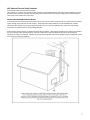
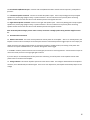
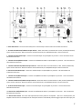
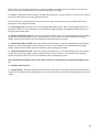
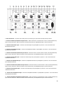
 2
Emotiva X‐Series Amplifiers – Table of Contents SAFETY PRECAUTIONS 5 NEC (National Electrical Code) Standards A Note for the Cable Television (CATV) Installer Antenna Grounding Outside the House 7
7
7
Thank You For Your Purchase 8 Emotiva X‐Series Amplifiers Overview 9 X‐Series Amplifier Features 10 Power Rating Note 10 Unpacking Your X Series Amplifier Inventory 11
11 Front Panel Layout 12 Back Panel Layouts XPA‐1 Back Panel XPA‐2 Back Panel XPA‐3 Back Panel XPA‐5 Back Panel 13
13
15
17
19 Installation and Connections AC Power Considerations Physical Placement/Heat Considerations Input Connection Considerations Output Connection Considerations Connection Tips for Superior Sound 22
22
22
23
23
23 Connection Diagram 24 Connection using a Multi‐Channel Preamp/Processor 25 Series and Parallel Speaker Connections 26 Series Connections 26 Parallel Connections 27 Technical Note about Multiple Speaker Connections 27 Table of Contents continues, next page 3
28
28
28
29
29
29
30
30
30 Troubleshooting Guide No Sound (from one or more speakers connected to the amplifier) The amplifier shuts down often or the line circuit breaker trips often Poor Bass Performance From Full Range Speakers connected to the amplifier Turn‐on and turn‐off thumps “Hum” Noises in the Speakers Other Probable Causes of Noise One or more RED lights on the Front Panel are Blinking Problems with the whole A/V System 31
31
32
33
34 TECHNICAL SPECIFICATIONS XPA‐1 Specifications XPA‐2 Specifications XPA‐3 Specifications XPA‐5 Specifications Limited Warranty 35 Service Assistance 35 Emotiva Disclosure 36 4
Safety Precautions Read this User’s Guide thoroughly before attempting to install and configure X Series Amplifier. All the safety and operation instructions should be read before any operation of the component(s) begin. After successful installation and configuration of the amplifier, be sure to retain this manual in a safe place for any future reference needs. All warning on the amplifier and in this Operation Manual should be followed. Safety is a key component to a long lasting, trouble free installation. The vast majority of the safety precautions are simply common sense. If you don't feel comfortable performing the installation of audio/video entertainment equipment, it is advised that you seek the services of a qualified installation professional. NEVER use X Series amplifiers near water such as a bathtub, washbowl, kitchen sink, laundry tub, in a wet basement, or near a swimming pool, etc. There is a risk of electric shock to your body and permanent damage to the equipment. Electric shock may result in permanent bodily injury or death. This amplifier should be installed in a location which provides adequate ventilation. The amplifier should not be installed on a bed, sofa, rug, or other similar surfaces that would block any of the ventilation openings; nor should the amplifier be installed in a closed environment that may impede airflow through the ventilation openings on the amplifier. Should you choose to install the amplifier in a closed equipment rack be sure to add forced air ventilation to provide adequate air circulation. The amplifier should be situated away from heat sources such as radiators or other heat producing devices. Emotiva amplifiers should be connected only to a power supply as described in this Operation Manual or shown on the label located on the back of the amplifier. The power cord should be routed so that it avoids high foot traffic areas; and, placement of the power cord should avoid locations where heavy items may be place upon or against it. Special attention should be given where the power cord will plug into the wall outlet, convenience receptacles, and the point where the power cord attaches to X Series Amplifier. The power cord of the amplifier should be unplugged from the outlet when unused for a long period of time. Never spray liquids directly into the component’s vent openings. Care should be taken so that small objects do not fall into the inside of the amplifier. The following situatio ns require your Emotiva X Series Amplifier is serviced only by qualified service personnel: • The power‐supply cord or the plug has been damaged; or Objects have fallen, or liquid has spilled into the component; or • The X Series Amplifier has been exposed to rain; or • The X Series Amplifier does not appear to operate normally or exhibits a marked change in performance; or • The X Series Amplifier has been dropped, or its enclosure or chassis is damaged. The user should not attempt to service the X Series Amplifier beyond the means described in this Operation Manual. All other servicing should be referred to Emotiva's service personnel. 5
To prevent electric shock, do not use this polarized plug with an extension cord, receptacle or other outlet unless the blades can be fully inserted to prevent blade exposure. Grounding or Polarization — Precautions should be taken so that the grounding or polarization means of the component is not defeated. This apparatus does not exceed the Class A /Class B (whichever is applicable) limits for radio noise emissions from digital apparatus as set out in the radio interference regulations of the Canadian Department of Communications. For questions regarding service, please contact: EMOTIVA Toll Free – 877‐EMO‐TECH www.emotiva.com WARNING: TO REDUCE THE RISK OF FIRE OR ELECTRIC SHOCK, DO NOT EXPOSE THIS APPLIANCE TO RAIN OR MOISTURE. CAUTION: TO PREVENT ELECTRIC SHOCK, MATCH WIDE BLADE OF PLUG TO WIDE SLOT, FULLY INSERT. 6
NEC (National Electrical Code) Standards A Note for the Cable Television (CATV) Installer This reminder is to call the CATV system installer’s attention to Article 820‐40 of the NEC that provides guidelines for proper grounding and in particular, specifies that the cable ground shall be connected to the grounding system of the building as close to the point of cable entry as practical. Antenna Grounding Outside the House If an outside antenna is connected to the receiver, be sure the antenna system is grounded so as to provide some protection against voltage surges and built‐up static charges. Article 810 of the National Electrical Code, ANSI/NFPA 70, provides information with regard to proper grounding of the lead‐in wire to an antenna‐discharge unit, connection to grounding electrodes, and requirements for the grounding electrode. Always observe proper antenna or satellite dish grounding techniques. When lightning strikes there is always the possibility that your antenna or dish (mounted high on the roof) can become a conduit for lightning and electrically damage any equipment to which it’s connected. Additionally, proper grounding offers safety to the people using the audio/video system in the event of an electrical problem. 7
Thank You for your Purchase We’re happy you chose Emotiva Audio! We believe our products set a new standard for performance and value. Emotiva amplifiers are designed for maximum performance, ease of use, and simple installation. Our experienced engineers use practical, proven designs, along with innovative ideas to create amplifiers that will easily power your speakers at any level while remaining as efficient as possible. Enjoy audio and video sources without concern for dynamic headroom during complex musical passages and high‐level effects – and with a sound quality that will satisfy the most discriminating listener. Our amplifiers are built for decades of reliable use, with a full five year warranty on all parts and labor. Our staff is a phone call away, ready to assist you if needed. We stand behind our products 100 percent, and we know that earning your trust and patronage depends on our continuing commitment to excellence in every way. Emotiva started with an idea – the idea of audio enthusiasts building gear that satisfied their own high standards, and sharing it with fellow enthusiasts, with no one in the middle. Just the best possible gear at the best possible prices, direct to you. We wish you many hours of enjoyment with your Emotiva purchase. Welcome to the family! Dan Laufman, President, Emotiva Audio Corporation 8
Emotiva X Series Amplifiers Overview The X series amplifiers were designed for multiple applications, and work well in both home theater and musical settings. They were engineered to be highly responsive, dynamic and deliver a clear, neutral and natural sound. XPA‐1 This amplifier works extremely well for stereo use (requires two amplifiers), and offers an extremely dynamic home theater experience – tons of power while retaining an open, relaxed sound miles away from listening fatigue. Fully balanced with a quad differential input stage and a discrete front end. It features 24 output devices and delivers 500 watts into 8 ohms, and 1,000 into 4 ohms. The XPA‐1 is for serious audiophiles who want a very detailed, clean sound. Recommended for left and right channels, left, right, and center channels, or all channels (one amplifier per channel) XPA‐2 This two channel amplifier packs a punch as either a stand‐alone stereo amplifier, or as an amplifier for the left and right channels in your home theater. Combining it with an XPA‐5 makes a formidable 7 channel system. The XPA‐2 boasts a larger transformer than the XPA‐5 or XPA‐3, as well as more secondary capacitance, larger power modules and higher rail voltage. An extremely robust output section (12 output devices) maximizes power and delivers exceptional performance. Rated at 250 watts into 8 ohms, 500 watts into 4 ohms (minimum rating – it will peak higher). The XPA‐2 is also bridgeable (for 8 ohm loads), transforming it into a potent monoblock. XPA‐3 The XPA‐3 was brought to the X family as a ‘turbo charger’ for the average receiver. Simply put, a receiver’s amplifier cannot compete with a separate amp. It’s just simply physics, due to the space limitations within the receiver. The XPA‐3 rates at 200 watts per channel (8 ohms), and was designed to be used to power the left, right and center channels, giving the receiver enough breathing space to adequately power the surrounds. Of course, it can be used with other amplifiers in various configurations, with or without using a receiver. XPA‐5 The first X series amplifier, and still the most popular. This five channel amplifier was the answer to the constant request for ‘more headroom, please’. An amplifier with ‘headroom’ has a power supply capable of peaking well beyond its continuous rating, making it extremely dynamic, while retaining clear imaging and detail. At 200 watts into 8 ohms (300 into 4 ohms), the XPA‐5 immediately raised the bar and became a classic. The backbone of a serious home theater and stereo system, and easily combined with an XPA‐2 for an absolute knockout of a 7 channel setup. 9
X Series Amplifier Features: •
•
•
•
•
•
•
•
•
•
•
•
•
•
•
Audiophile quality performance and sound High current power supply Low noise toroidal power transformer Complementary, discrete power amplifier design incorporating high current, high speed, On Semiconductor power devices Channel status indicators for standby, operate, and fault 12 volt trigger connections Completely stable into 4 ohm loads Signal to Noise Ratio is greater than 100dB, unweighted ref. full output THD .03% at rated power, 20Hz – 20kHz Fully protected from all fault conditions Soft start circuitry External trigger turn on Soft touch power switch Heavy duty, rack standardized chassis w/ solid milled aluminum faceplate IEC power inlet, 115/230 VAC Auto configurable Power Rating Note: ‘Peak’ vs. ‘Continuous’ Many companies will rate an amplifier with only one or two channels driven under load, which results in reporting inflated power output.. In real life, this will drop significantly when all channels are driven. This is called ‘peak’ power conditions (Peak Music Power Output, or PMPO). ‘Peak power’ represents the maximum amount of power that an amplifier/receiver can deliver without being damaged. Ratings are performed this way for the sole reason of exaggerating the perceived power of the product, and during normal use, the actual practical power output is much lower than the claimed ‘peak’ rating. Sometimes these ratings are also performed at 10% THD, even thought the industry accepted level is 1.0% THD. This practice has led many people to seek higher and higher levels of power in amplifiers because they misunderstand the difference between ‘peak’ and ‘continuous’ power. All Emotiva amplifiers are rated for continuous power, tested with all channels driven simultaneously. We at do not play games with the specifications, and test all of our amplifiers to industry standard test conditions with the amplifier put under the strictest loads. This means that the power output and other specifications listed are the bare minimum (or worst case scenario) you will receive from our amplifiers. Under normal circumstances you will get much higher output then what is rated. The bottom line is this: These amplifiers are powerful, and can give you control over your sound in ways a receiver could never come close to. We’re proud to offer amazing performance to match the amazing value of the X Series amplifiers. 10
Unpacking Your X Series Amplifier All Emotiva amplifiers are double boxed to survive the rigors of long distance shipping and arrive to you undamaged. The outer box may show wear and tear, but this is no cause for alarm. The outer box’s purpose is to protect the inner box. If the inner looks heavily damaged, and you are concerned about damage to the amplifier, please call Emotiva Technical Support at 877‐366‐8324 (877‐EMO‐Tech). Inside the laminated inner box, the amplifier is securely seated between to two reinforced pieces of high‐density impact foam. At first glance, the cardboard backing on the foam may give the appearance of a third box, but it is easily lifted to reveal the amplifier, which is wrapped in static free plastic. The plastic sheeting is tucked underneath the amplifier and securely taped. It is recommended that the plastic sheeting be removed after the amp is lifted out from the box. The bottom piece of foam is molded to fit tightly against the amplifier, but there is a recessed area on each side, allowing you to get your hands under the amplifier and lift it out of the box. Note: These amplifiers are HEAVY! Lift with your legs! Inventory Included with your X amplifier should be an IEC Class 1, 2 prong power cord, and this User’s Guide. Emotiva amplifiers are double insulated and do not require a grounded plug. Much care has been taken to make sure that your amplifier is safe, completely shielded, insulated and grounded. It is important to save all the packing materials and the box in case your X amplifier ever needs to be moved or shipped for servicing. 11
Front Panel Layout The face of an XPA‐5 is shown above. Although there is variation within the X‐Series amplifiers faceplates, the basic features are the same: a power button and LED Status window. 1. Front Panel LED Display The front panel display contains Status LED lighting to indicate the operation status of the amplifier. • NO LED = Amplifier is OFF • BLUE LED = Normal Operation • FLASHING RED LED = Fault Condition ‐ see “Troubleshooting” section for details. Note: The back panel of each amplifier has an LED Status Selector which can turn the blue LEDs off. 2. Front Panel Power Switch This switch provides the ON/OFF control of the amplifier from the front panel. When the unit is off and in standby mode, the switch illuminates amber. Automatic switching is accomplished with the 3.5mm trigger input on the back panel using a 5‐12V DC control signal. Note On Amplifier Supports: Do not remove the supports or ‘feet’ from your amplifier. In addition to minimizing vibration and insulating the amplifier from the surface it is placed on, these feet are essential in allowing airflow under the amplifier for proper cooling. 12
Back Panel Layouts XPA‐1 Back Panel 1. Rubber Terminal Protector – Four terminal protectors extend 1.5 inches from the back plate of the amplifier to absorb shock and protect the terminals when they are close to a wall or other surface. 2. Negative Speaker Terminals – Connects to the negative speaker inputs. These 5 way binding posts accept stripped speaker wire, banana plugs, or spade connectors. Be sure to observe correct polarity when connecting speakers and be sure that the wires do not touch between positive and negative terminals. When using the XPA‐1 to ‘bi‐wire’ a speaker, use both negative and both positive terminals to connect to the corresponding negative and positive terminals on your speakers. In a standard wiring situation, use only one negative terminal and one positive terminal to single negative and positive terminals on the speaker. Note: Potentially lethal voltages present! Never connect, disconnect or modify speaker wiring with the amplifier turned on. 3. Meter/LED Status Selectors – The status LED (single LED that lights when the unit is on) and meter LEDs (which move in sync with the amplifier output) on the amplifier faceplate can be turned on or off with these selectors. 4. Remote Trigger Input/Output – The XPA‐1 can be remotely triggered by another device, and in turn, remotely trigger another device. When a remote trigger output from a preamplifier, processor or other audio device is connected to the trigger input here, the amplifier will power up and shut down along with the first device. Another device (CD player, amplifier, etc) can be added to this chain using the trigger output. A 3.5mm, 5‐12 volt mono audio cable is used for both inputs and outputs. If building your own cable, center is positive and outer shield is negative. 5. RCA Audio Input – Connects to the RCA output of a preamplifier or processor. This is marked ‘Un‐Bal’ because it is an unbalanced connection. 13
6. Balanced/Unbalanced Input Selection Switch – When the switch is turned towards ‘Un‐Bal’, the RCA (unbalanced) input is
chosen and active. When the switch is turned towards ‘Bal’, the XLR/Balanced input is chosen and active.
7. XLR/Balanced Audio Input – Connects to the XLR/Balanced output of a preamplifier or processor.
8. Positive Speaker Terminals – Connects to the positive speaker inputs. These 5 way binding posts accept stripped speaker
wire, banana plugs, or spade connectors. Be sure to observe correct polarity when connecting speakers and be sure that the
wires do not touch between positive and negative terminals.
When using the XPA‐1 to ‘bi‐wire’ a speaker, use both negative and both positive terminals to connect to the corresponding
negative and positive terminals on your speakers. In a standard wiring situation, use only one negative terminal and one
positive terminal to single negative and positive terminals on the speaker.
Note: Potentially lethal voltages present! Never connect, disconnect or modify speaker wiring with the amplifier turned
on.
9. IEC Power Cable Connection
10. Master Power Switch ‐ This rocker switch provides the master power for the amplifier. After it is in the ON position, the
amplifier can be turned on manually from the front panel switch or automatically with the trigger input via 3.5mm input jack.
Under normal use, this switch should remain on, leaving the amplifier in standby position, and coming to full power with
either the front panel ‘STANDBY’ button, or activation through the remote trigger.
In ‘STANDBY’ mode the power button will emit an amber glow, but the unit is not fully powered. A small amount of amps are
used in this mode, less than an average night light would use.
If you are away for an extended period of time (more than a few days), shut off all power to the amplifier with the main
power switch on the back of the amplifier.
11. Voltage Indicator – All Emotiva amplifiers operate on either 115V or 230V. The voltage is detected when the amplifier is
turned on, and is identified by the indicator lights. There are no user adjustments, the amplifier automatically adjusts to the
voltage.
14
XPA‐2 Back Panel 1. Remote Trigger Input ‐ The XPA‐2 can be remotely triggered by another device. When a remote trigger output from a preamplifier, processor or other audio device is connected to the trigger input here, the amplifier will power up and shut down along with the first device. A 3.5mm, 5‐12 volt mono audio cable is used for both inputs and outputs. If building your own cable, center is positive and outer shield is negative. 2. Working LED Selector – The two ‘On’ status LEDs (one for each channel) on the amplifier faceplate can be turned on and off with this selector. 3. Meter LED Selector – The meter LEDs (which move in sync with amplifier output) can be turned on and off with this selector. 4. Right Channel XLR/Balanced Input – Connects with an XLR/Balanced cable to the right channel output of a preamplifier or processor. 5. Right Channel Balanced/Unbalanced Input Selector – When turned towards ‘Un‐Bal’, the RCA (unbalanced) input is chosen and active. When turned towards ‘Bal’, the XLR/Balanced input is chosen and active. 6. Right Channel RCA /Unbalanced Input ‐ Connects with an RCA/Unbalanced cable to the right channel output of a preamplifier or processor. 7. Bridged Configuration Selector – Leaving this selector on ‘OFF’ keeps the XPA‐2 in standard two channel mode. Turning it to ‘ON” bridges the two separate channels into one, turning the XPA‐2 into a monoblock amplifier. NOTE: Bridged mode is meant for use with 8 ohm speakers. Using bridged mode with lower impedence speakers may cause overheating, causing the amplifier to go into protect mode (fault), and possibly sustain permanent damage. 8. Left Channel RCA /Unbalanced Input ‐ Connects with an RCA/Unbalanced cable to the left channel output of a preamplifier or processor. 9. Left Channel Balanced/Unbalanced Input Selector – When turned towards ‘Un‐Bal’, the RCA (unbalanced) input is chosen and active. When turned towards ‘Bal’, the XLR/Balanced input is chosen and active. 15
10. Left Channel XLR/Balanced Input ‐ Connects with an XLR/Balanced cable to the left channel output of a preamplifier or
processor.
11. Left Channel Speaker Terminals ‐ Connects to the left side speaker inputs. These 5 way binding posts accept stripped
speaker wire, banana plugs (single or dual), or spade connectors. Be sure to observe correct polarity when connecting
speakers and be sure that the wires do not touch between positive and negative terminals.
12. Right Channel Speaker Terminals‐ Connects to the right side speaker inputs. These 5 way binding posts accept stripped
speaker wire, banana plugs (single or dual), or spade connectors. Be sure to observe correct polarity when connecting
speakers and be sure that the wires do not touch between positive and negative terminals.
Note: Potentially lethal voltages present! Never connect, disconnect or modify speaker wiring with the amplifier turned
on.
13. IEC Power Cable Connection
14. Master Power Switch ‐ This rocker switch provides the master power for the amplifier. After it is in the ON position, the
amplifier can be turned on manually from the front panel switch or automatically with the trigger input via 3.5mm input jack.
Under normal use, this switch should remain on, leaving the amplifier in standby position, and coming to full power with
either the front panel ‘STANDBY’ button, or activation through the remote trigger.
In ‘STANDBY’ mode the power button will emit an amber glow, but the unit is not fully powered. A small amount of amps are
used in this mode, less than an average night light would use.
If you are away for an extended period of time (more than a few days), shut off all power to the amplifier with the main
power switch on the back of the amplifier.
15. Voltage Indicator ‐ All Emotiva amplifiers operate on either 115V or 230V. The voltage is detected when the amplifier is
turned on, and is identified by the indicator lights. There are no user adjustments, the amplifier automatically adjusts to the
voltage.
16
XPA‐3 Back Panel 1. Status LED Selector ‐ The three status LEDs (one for each channel) can be turned on and off with this selector. 2. Channel Three Balanced/Unbalanced Input Selector – When the switch is turned towards ‘Un‐Bal’, the RCA (unbalanced) input is chosen and active. When the switch is turned towards ‘Bal’, the XLR/Balanced input is chosen and active. 3. Channel Three RCA Audio Input – Connects to the RCA output of a preamplifier or processor. This is the Channel Three unbalanced connection. 4. Channel Three XLR/Balanced Input – Connects an XLR/Balanced cable to a preamplifier or processor. This is the Channel Three balanced connection. 5. Channel Two Balanced/Unbalanced Input Selector – When the switch is turned towards ‘Un‐Bal’, the RCA (unbalanced) input is chosen and active. When the switch is turned towards ‘Bal’, the XLR/Balanced input is chosen and active. 6. Channel Two RCA Audio Input – Connects to the RCA output of a preamplifier or processor. This the Channel Two unbalanced connection. 7. Channel Two XLR/Balanced Input – Connects an XLR/Balanced cable to a preamplifier or processor. This is the Channel Two balanced connection. 8. Channel One Balanced/Unbalanced Input Selector – When the switch is turned towards ‘Un‐Bal’, the RCA (unbalanced) input is chosen and active. When the switch is turned towards ‘Bal’, the XLR/Balanced input is chosen and active. 9. Channel One RCA Audio Input – Connects to the RCA output of a preamplifier or processor. This the Channel One unbalanced connection. 10. Channel One XLR/Balanced Input – Connects an XLR/Balanced cable to a preamplifier or processor. This is the Channel One balanced connection. 11. Master Power Switch ‐ This rocker switch provides the master power for the amplifier. After it is in the ON position, the amplifier can be turned on manually from the front panel switch or automatically with the trigger input via 3.5mm input jack. 17
Under normal use, this switch should remain on, leaving the amplifier in standby position, and coming to full power with either the front panel ‘STANDBY’ button, or activation through the remote trigger. In ‘STANDBY’ mode the power button will emit an amber glow, but the unit is not fully powered. A small amount of amps are used in this mode, less than an average night light would use. If you are away for an extended period of time (more than a few days), shut off all power to the amplifier with the main power switch on the back of the amplifier. 12. Remote Trigger Input ‐ The XPA‐3 can be remotely triggered by another device. When a remote trigger output from a preamplifier, processor or other audio device is connected to the trigger input here, the amplifier will power up and shut down along with the first device. 13. Channel Three Speaker Terminals ‐ Connects to the left side speaker inputs. These 5 way binding posts accept stripped speaker wire, banana plugs (single or dual), or spade connectors. Be sure to observe correct polarity when connecting speakers and be sure that the wires do not touch between positive and negative terminals. 14. Channel Two Speaker Terminals ‐ Connects to the left side speaker inputs. These 5 way binding posts accept stripped speaker wire, banana plugs (single or dual), or spade connectors. Be sure to observe correct polarity when connecting speakers and be sure that the wires do not touch between positive and negative terminals. 15. Channel One Speaker Terminals ‐ Connects to the left side speaker inputs. These 5 way binding posts accept stripped speaker wire, banana plugs (single or dual), or spade connectors. Be sure to observe correct polarity when connecting speakers and be sure that the wires do not touch between positive and negative terminals. Note: Potentially lethal voltages present! Never connect, disconnect or modify speaker wiring with the amplifier turned on. 16. IEC Power Cable Connection 17. Voltage Indicator ‐ All Emoitva amplifiers operate on either 115V or 230V. The voltage is detected when the amplifier is turned on, and is identified by the indicator lights. There are no user adjustments, the amplifier automatically adjusts to the voltage. 18
XPA‐5 Back Panel 1. Status Led Selector ‐ The three status LEDs (one for each channel) can be turned on and off with this selector. 2. Channel Five Balanced/Unbalanced Input Selector – When the switch is turned towards ‘Un‐Bal’, the RCA (unbalanced) input is chosen and active. When the switch is turned towards ‘Bal’, the XLR/Balanced input is chosen and active. 3. Channel Five RCA Audio Input – Connects to the RCA output of a preamplifier or processor. This is the Channel Five unbalanced connection. 4. Channel Five XLR/Balanced Input – Connects an XLR/Balanced cable to a preamplifier or processor. This is the Channel Five balanced connection. 5. Channel Four Balanced/Unbalanced Input Selector – When the switch is turned towards ‘Un‐Bal’, the RCA (unbalanced) input is chosen and active. When the switch is turned towards ‘Bal’, the XLR/Balanced input is chosen and active. 6. Channel Four RCA Audio Input – Connects to the RCA output of a preamplifier or processor. This is the Channel Four unbalanced connection. 7. Channel Four XLR/Balanced Input – Connects an XLR/Balanced cable to a preamplifier or processor. This is the Channel Four balanced connection. 8. Channel Three Balanced/Unbalanced Input Selector – When the switch is turned towards ‘Un‐Bal’, the RCA (unbalanced) input is chosen and active. When the switch is turned towards ‘Bal’, the XLR/Balanced input is chosen and active. 9. Channel Three RCA Audio Input – Connects to the RCA output of a preamplifier or processor. This is the Channel Three unbalanced connection. 10. Channel Three XLR/Balanced Input – Connects an XLR/Balanced cable to a preamplifier or processor. This is the Channel Three balanced connection. 11. Channel Two Balanced/Unbalanced Input Selector – When the switch is turned towards ‘Un‐Bal’, the RCA (unbalanced) input is chosen and active. When the switch is turned towards ‘Bal’, the XLR/Balanced input is chosen and active. 19
12. Channel Two RCA Audio Input – Connects to the RCA output of a preamplifier or processor. This is the Channel Two
unbalanced connection.
13. Channel Two XLR/Balanced Input – Connects an XLR/Balanced cable to a preamplifier or processor. This is the Channel
Two balanced connection.
14. Channel One Balanced/Unbalanced Input Selector – When the switch is turned towards ‘Un‐Bal’, the RCA (unbalanced)
input is chosen and active. When the switch is turned towards ‘Bal’, the XLR/Balanced input is chosen and active.
15. Channel One RCA Audio Input – Connects to the RCA output of a preamplifier or processor. This is the Channel One
unbalanced connection.
16. Channel One XLR/Balanced Input – Connects an XLR/Balanced cable to a preamplifier or processor. This is the Channel
One balanced connection.
17. Master Power Switch ‐ This rocker switch provides the master power for the amplifier. After it is in the ON position, the
amplifier can be turned on manually from the front panel switch or automatically with the trigger input via 3.5mm input jack.
Under normal use, this switch should remain on, leaving the amplifier in standby position, and coming to full power with
either the front panel ‘STANDBY’ button, or activation through the remote trigger.
In ‘STANDBY’ mode the front panel button will emit an amber glow, but the unit is not fully powered. A small amount of
amps are used in this mode, less than an average night light would use.
If you are away for an extended period of time (more than a few days), shut off all power to the amplifier with the main
power switch on the back of the amplifier.
18. Remote Trigger Input ‐ The XPA‐3 can be remotely triggered by another device. When a remote trigger output from a
preamplifier, processor or other audio device is connected to the trigger input here, the amplifier will power up and shut
down along with the first device.
19. Channel Five Speaker Terminals ‐ Connects to the channel 5 speaker inputs. These 5 way binding posts
accept stripped speaker wire, banana plugs (single or dual), or spade connectors. Be sure to observe correct polarity when connecting
speakers and be sure that the wires do not touch between positive and negative terminals.
20. Channel Four Speaker Terminals ‐ Connects to the channel 4 speaker inputs. These 5 way binding posts accept stripped
speaker wire, banana plugs (single or dual), or spade connectors. Be sure to observe correct polarity when connecting
speakers and be sure that the wires do not touch between positive and negative terminals.
21. Channel Three Speaker Terminals ‐ Connects to the channel 3 speaker inputs. These 5 way binding posts accept
stripped speaker wire, banana plugs (single or dual), or spade connectors. Be sure to observe correct polarity when connecting
speakers and be sure that the wires do not touch between positive and negative terminals.
22. Channel Two Speaker Terminals ‐ Connects to the channel 2 speaker inputs. These 5 way binding posts accept
stripped speaker wire, banana plugs (single or dual), or spade connectors. Be sure to observe correct polarity when connecting
speakers and be sure that the wires do not touch between positive and negative terminals.
23. Channel One Speaker Terminals ‐ Connects to the channel 1 speaker inputs. These 5 way binding posts accept
stripped speaker wire, banana plugs (single or dual), or spade connectors. Be sure to observe correct polarity when connecting
speakers and be sure that the wires do not touch between positive and negative terminals.
Note: Potentially lethal voltages present! Never connect, disconnect or modify speaker wiring with the amplifier turned
on.
24. IEC Power Cable Connection
20
25. Voltage Indicator ‐ All Emotiva amplifiers operate on either 115V or 230V. The voltage is detected when the amplifier is turned on, and is identified by the indicator lights. There are no user adjustments, the amplifier automatically adjusts to the voltage. 21
Installation and Connections AC Power Considerations The majority of household electrical sockets (in places other than the kitchen and garage) are 15 amperes maximum, which is sufficient to power your X series amplifier. However, remember to account for the electrical power that other components will require if they share a common wall socket or electrical circuit. Most DVD players, preamplifiers and A/V source units are fairly low current items, and can successfully share a wall socket with your power amplifier, but big screen TVs and video projectors usually have minimum current requirements that can consume nearly an entire circuit. Refer to the owner’s manuals of your audio/video devices to assess your electrical power requirements for your home entertainment system. If you have any questions relating to issues with the power requirements for your X amplifier, please contact Emotiva Support at: 877‐366‐8324 (877‐EMO‐Tech) Surge Protection ‐ Along with built‐in noise filtering, your X Series amplifier is equipped with overcurrent, undercurrent, and spike protection. Upon powering up your X amplifier with the front panel switch or via 3.5mm trigger input (switch on the rear panel must be set to “ON”), you will notice the front panel LED lighting starts off red for 5 seconds and then turns to blue. This indicates the amplifier is “on,” functioning normally and ready for operation. If you do not see an LED light or a blinking red LED light while the amplifier is on during (otherwise) normal operation, please refer to the troubleshooting section of this manual. Physical Placement /Heat Considerations X series amplifiers employ convection cooling, which is very effective and completely noiseless. Under normal operating conditions, your X amplifier will remain cool to mildly warm, but considerations for heat should be taken into account during placement. Place your X amplifier on a flat, level surface, with the weight distributed equally on all four feet. If using a cabinet or shelf, please make sure that there is sufficient ventilation and there is at least 6 inches of free air space above the amplifier and 3 inches on each side. If adequate ventilation is not available, your may consider installing two small brushless DC fans (such as those used in computer cases) to provide continuous airflow around the unit. If the amplifier is located on a carpeted surface, place a board under the amplifier’s feet. NOTE: Expansion and contraction of the amplifier’s heat sinks may cause a faint ‘clicking’ sound at times. This is relative to how warm the heat sinks become and how quickly they cool. This is completely normal, and no cause for concern. Do NOT block the ventilation holes on the amplifier. Your X amplifier is equipped with a massive toroidal power transformer. This transformer generates a magnetic field that could induce a hum in a turntable (particularly a turntable equipped with a moving coil cartridge). Do NOT place a turntable directly above or directly adjacent to the amplifier. Before placing the amplifier on a shelf, verify that the weight bearing capacity of the shelf is 80 lbs or greater. The amplifier is heavy and should be placed toward the bottom of an audio rack to minimize the rack being unnecessarily top heavy. 22
Input Connection Considerations High quality, fully shielded RCA or XLR cables are recommended for use with X amplifiers. ‘Twisted Pair’ cables are not recommended. X amplifiers have an extremely high bandwidth, and twisted, non‐shielded cables can actually act as an ‘antenna’, receiving outside interference and signals (EMI and RFI), which will cause the amplifier to go into protect mode. Whenever possible, keep preamplifier level audio cables away from amplifier electrical power cords by at least a few inches. Amplifier AC power cords are carrying much more current than other source and preamplifier components, which means there is a larger degree of noise or “hum” potential with the amplifier power cord in close proximity. Output Connection Considerations The output connectors provided on each channel of X amplifiers are standard “binding post” speaker connectors with industry standard spacing. These are sometimes called 5‐way binding posts because of the many ways in which the speaker wire can connect into the posts. The posts can accept bare wire, spade terminals, or single banana connectors. Keep in mind that if you use “dual banana” plugs and “stack” them, you will be creating a parallel connection. For more details on series and parallel connections, see pages 26‐27. It is important to observe polarity so that the speaker wire connects to the red and black terminals on the amplifier and the corresponding terminals at the speaker. Also, make sure that the positive speaker wires do not touch the negative speaker wires, or any chassis metal. This will cause a short circuit and activate the protection circuitry. Connection Tips for Superior Sound Before setting up your new system, please consider the following: • Always make sure the amplifier is turned off before making or changing ANY connections. • Whenever possible, route the power cords away from the signal cables or speaker wires to prevent any hum or interference heard in the speakers. • Many RCA type patch cords can be a very tight fit and there is usually a preferred method of removing them. Some have to be removed with a twisting action. Be gentle or you may damage the jacks of your amplifier, the cables themselves, or other components. • Many audiophile signal cables are intended to be hooked up in one direction. If this is the case, the cables will be marked with arrows indicating the direction of signal flow. • It is usual for the right channel RCA patch cord plugs to be red and the left channel connections to be white, grey, or black (depending on the cable brand). RCA connectors that are gold will be designated with a colored band to designate the channel. 23
Connection Diagram (using an XPA‐5 for example) 24
Connections Using a Multi‐Channel Preamp/Processor with Speakers The diagram on the preceding page depicts an XPA‐5 connected to an Emotiva UMC‐1 Multi‐Channel Processor/Preamplifier. Your personal setup may differ, depending on which amplifier you own, and how many channels you are using. The XPA‐5 is simply shown as a basic example. The image shows a basic 5‐channel surround configuration connecting the RCA/Unbalanced outputs on the processor to the RCA/Unbalanced inputs on the amplifier. Note that each channel on the XPA‐5 has been switched to ‘Un‐Bal’ (for an RCA/Unbalanced connection) using the Balanced/Unbalanced Selectors. If the selector does not match the connection type, the amplifier channel in question does not pass the signal to the speakers, and that channel will remain silent. The preamplifier outputs on the processor are labeled as follows: L (Left), LS (Left Surround), C (Center), LBS (Left Back Surround), R (Right), RS (Right Surround), SW (Subwoofer), and RBS (Right Back Surround). Connect the outputs from the processor to the amplifier channels you wish to use to power each speaker. Example: You plan to use Channel 1 on the amplifier to power your front left speaker. With an RCA/Unbalanced cable, connect the output labeled ‘L’ to the unbalanced input on amplifier Channel 1. Then, connect the speaker terminals from amplifier Channel 1 to your front left speaker. Continue this process for all connections, making sure to keep the outputs, inputs and speaker terminal connections in order. If your processor/preamplifier has XLR/Balanced outputs, the Balanced inputs on your X‐Series amplifier may be used. Simply switch your channel selectors to ‘Bal’, and use the XLR/Balanced outputs on the processor, and the XLR/Balanced inputs on each channel of the amplifier. Surround Speakers Note: In a standard five channel configuration, LS (Left Surround) and RS (Right Surround) are used, and LBS (Left Back Surround) and RBS 9 (Right Back Surround) are left unused. In a standard seven channel configuration, LBS and RBS are included. Subwoofer Note: As seen in the diagram, the subwoofer output on the processor (shown as a XLR/Balanced connection) goes directly to the subwoofer itself. This assumes that the subwoofer has its own amplifier. If the subwoofer has a separate amplifier, the processor output would first go to the input of the amplifier, then to the subwoofer. 25
Series and Parallel Speaker Connections Whenever connecting more than one speaker per channel to an amplifier, you must consider the way in which the amplifier will be impacted by adding the additional speaker(s). Additionally, speakers with dual voice coils also apply to this consideration. Two voice coils in a single speaker also cause different reactions from an amplifier depending on the way in which they connect to the amplifier. The connection of more than one speaker per channel will make the amplifier run warmer. For the best sonic results, use one speaker per amplifier channel. If you must connect more than one speaker per channel, there are two methods in which to do so: Series and Parallel. Series Connection A series connection is established when voice coils are connected in a string – end to end – so there’s only one way for audio signals to flow “in” and only one way for audio signals to flow “out”. For example, if you were to series‐connect two speakers to the front right channel of the amplifier: • The positive output terminal of the right channel connects to the positive input post of the first speaker. • The negative input post of the first speaker connects to the positive input post of the second speaker. • The negative input post of the second speaker connects to the speaker's negative output terminal of the right channel. The total impedance of speakers in series is found by adding their impedances together. For example; two, four‐ohm speakers in series is an eight‐ohm load. Series connections are easier on the amplifier than parallel connections as the total impedance is higher than driving a single speaker. An example of a SERIES connection between two speakers. 26
Parallel Connections A parallel circuit is established when voice coils are connected in a way that there are multiple paths for audio signals to flow “in” and multiple paths for audio signals to flow “out”. When speakers are connected in parallel, the total resistance at the amplifier is proportionally divided based on the value of each individual voice coil resistance. The term “divided” simply means all of the values together in parallel are a SMALLER value than each all by itself. For example, if you were to parallel connect two speakers to the front right channel of the amplifier: The positive output terminal of the right channel connects to the positive input post of the first speaker and to the positive post of the second speaker. An example of a PARALLEL connection between two speakers. The negative output terminal of the right channel connects to the negative input post of the first speaker and to the negative post of the second speaker. The total impedance of equal speakers in parallel is found by dividing the impedance of one speaker by the number of speakers. For example; two, eight‐ohm speakers in parallel is a four‐ohm load (eight ohms divided by two), four eight‐ohm speakers in parallel is a two‐ohm load (eight ohms divided by four). Two‐ohm single channel loads are NOT RECOMMENDED! Running your amplifier below recommended impedance level can cause excessive heat and will eventually drive the amplifier into protect mode (blinking red LED’s on the front of the unit). Parallel connections are harder on the amplifier than series connection, as the total impedance is lower compared to driving a single speaker, and the amplifier must produce more current to drive them. Ideally, the total average impedance should be no less than 4 ohms per channel. You must make sure that the lower impedance does not cause the amplifier to overheat, shut down, or trip your circuit breaker. If this happens, you should reduce the number of speakers wired in parallel, rewire them in series, or use more than one power amplifier. Technical Note about Multiple Speaker Connections Although there are two possible connection types discussed in this manual, it is imperative that with either connection type that you use loudspeakers of the same type and nominal impedance for these connections. In doing so, you have the most predictable outcome for your installation. When speakers of different nominal impedances and/or different bandwidths are used, there are many other acoustic problems that come into play in addition to complex impedance at the amplifier’s speaker output terminals. If you must use multiple speakers on any individual amplifier channel, please use speakers as close to identical as possible. 27
Troubleshooting Guide X Series amplifiers are expertly designed and built to provide years of trouble‐free performance. Most problems that occur can usually be solved by checking your setup or making sure that the audio and video components connected to the amplifier are on and fully operational. NOTE: Before turning on your amplifier for the first time, be sure to check: 1. The Balanced/Unbalanced selectors for each amplifier channel (located on the back panel). If the selection does not match the connection, the channel will not work. Make sure that you are selecting the proper type of connection for the cables you are using. 2. The status and meter LED selectors on the back panel. If these are in the ‘off’ position, the status and meter LEDs will not light. The following information will help you deal with other common setup problems you may experience during normal use of your unit. If problems persist, contact Emotiva support for help. No Sound (from one or more speakers connected to the amplifier) • Speaker cables may have come undone. Turn off your system and check the cables, tighten the amplifier and speaker binding posts. • Damaged audio cable. • The preamplifier volume level is low for the channels concerned. Recheck the preamplifier calibration procedure. • A preamplifier Mute switch may be on, an external processor loop or a tape monitor loop is engaged. • Check that your preamplifier or source is running the correct surround mode. Maybe it is set for 2‐channel stereo when you were expecting 5.1 surround sound. • Check if any missing channels have been turned off in a preamplifier setup menu. For example, the center amplifier channel will not receive a signal if the preamplifier has been set to “Phantom”. • Check main power switch to make sure that it is in on position (1). • An internal fuse on the unit may have blown. Contact Emotiva Support for assistance. The amplifier shuts down often or the line circuit breaker trips often • Check that the positive and negative speaker wires are not shorted together. • Make sure that no speakers are shorted internally. If you have an ohm‐meter, disconnect the speaker wires and measure the resistance between the speaker’s positive and negative terminals. • Measure all speakers and check their impedance specifications. If necessary, review the “Series and Parallel Connections” section in this manual. • If you have connected speakers in parallel, the overall impedance may be too low. It is recommended that you rearrange the speakers in series to increase the overall impedance, thus taking some load off the amplifier. • Make sure the amplifier has good ventilation and is not overheating. Allow good airflow underneath wherever possible. If the amplifier is in a closed rack, open up the rear panel or use a quiet fan for improved ventilation. 28
Poor Bass Performance from Full Range Speakers • Make sure that your preamp does not have the bass (tone control) level turned down. • Many surround preamplifiers have controls, which can direct all the bass to subwoofers, or let your main speakers play the full range. Make sure that the preamplifier has been correctly set. If you are not using a subwoofer, set the speaker options to “Large” where possible. • Check that the speaker wires have been connected correctly: Make sure that the positive of each speaker connects to a positive output of the amplifier, and the negative of each speaker connects to the negative output. If one speaker is wired incorrectly, then it will be “out of phase” with the others, resulting in poor bass performance. DOUBLE CHECK ALL THE SPEAKER CONNECTIONS!! Turn‐on and Turn‐off Thumps • Plug the amplifier into an un‐switched AC outlet, and use the 3.5mm Trigger Input connection with a trigger between 5‐12VDC from the source unit or preamplifier. This should allow the amplifier to turn on and off silently. • If your powered subwoofer is the cause of the “thump” sound (not the other speakers connected to the amplifier), plug it into a different 115VAC outlet than the amplifier so there is no power surge conflict. • Install a line‐conditioning device. “Hum” Noises in the Speakers • This problem is more than likely caused by a “ground loop” in your system, rather than a fault in the amplifier. Follow these steps to isolate the main cause of the hum; there may even be more than one. Remember to turn off all components in your system, including the amplifier, before disconnecting or connecting any cables during troubleshooting. • Try to have all of your equipment on the same electrical outlet or circuit. Group all the low power components (preamp, CD player, DVD etc.) on a single outlet or power strip. This is provided that the overall current draw from your equipment does not exceed the rating of the outlet or breaker. • Disconnect all cables, which come from outside the room, and check if the hum goes away. This includes such connections as cable TV, satellite TV, or roof top antennas. Make sure that they are disconnected where they first enter the room, so they are making no connection to the preamplifier or the TV, or any other component. If the hum is caused by the cable TV line, then you will need a “ground loop isolator.” This is an inexpensive device fitted in line with the coaxial cable feed. Contact your Cable Company or Emotiva for assistance. • Disconnect all connections from the preamplifier to your TV, VCR or DVD. • As a test, disconnect any other component, which has a grounded power cord. NOTE: Never remove the ground pin from any power cords (if present). This is very dangerous. If the hum persists, disconnect all the source components one at a time from the back of the preamplifier, until you identify the problem. • Try moving the speaker cables away from any power cords. Try just one speaker, connecting it to each amplifier channel and see if one channel is bad. Check that the interconnect cables to the amplifier do not have any broken connections. The best way to do this is to substitute a known good connection for the suspect connection. If you reverse the cables and the problem goes away, the cable may be damaged or broken. This is possible even if you can’t physically see the break as the strain for pulling on audio cables can sometimes break the wire internally. 29
Ground loop isolators are available for audio lines and video devices. If you need assistance, contact Emotiva. Although this is not always an ideal solution, the grounding differences between certain home entertainment components sometimes require ground loop isolators. This is the exception rather than the rule. Other Probable Causes of Noise • Speaker noise may also be caused by interference or noise on your AC line. Make sure there are no large appliances sharing the line, or halogen lamps or light‐dimming Triac devices. • Try connecting your system to another AC socket on a separate line. • If the hum is heard from within the amplifier, and not through the speakers, this may also be caused by interference on the AC or DC lines. The power transformers may turn this interference into an audible noise. Internal hum can be made worse by a shelf or cabinet resonating, so try moving the amplifier to another shelf. • Try moving your components further away from the TV, especially if you notice the screen has changed color in the area closest to the component. • If you have very high efficiency speakers, these may tend to reveal noises, which other speakers do not. One or more RED lights on the Front Panel are Blinking Your X Series Amplifier is equipped with a ‘Protect Mode’ to minimize the possibility of damage to either itself or speakers. If a problem is detected, the channel(s) at risk will shut down, following a red blinking on the corresponding indicator light(s). Each RED light indicates a fault condition for the corresponding power module. A fault condition is one or more of the following: • Excessive Operating Temperature • Excessive Current (Short Circuit) • DC on the Outputs An excessive temperature fault can be reset by allowing amplifier to cool and cycling power on/off button on the front panel. Excessive current (short circuit) can be reset by removing the cause of the short and cycling power on/off button on the front panel. DC at output is a possible fault condition that is equipment related and requires technical assistance. Please contact Emotiva if you have repeated problems causing the RED front panel light to flash that are NOT thermal or short circuit related. Problems with the whole A/V System If you are having more complex problems in your overall home entertainment system (not just with the amplifier), please contact Emotiva Support for assistance. 877‐EMO‐Tech (877‐366‐8324) 30
TECHNICAL SPECIFICATIONS: XPA‐1 Number of Channels: 1 Topology: Fully Discrete, Dual Differential, High Current, Short Signal Path Class A/B Power output (all channels driven): 1,000 watts RMS @ 4 ohm (0.1% THD) 500 watts RMS @ 8 ohm (0.1% THD) Power Band Response: 20 Hz to 20 kHz with less than .05db deviation at rated power Broadband Frequency Response: (‐3db): 5Hz to 150kHz Amplifier Gain: 32db Signal to Noise Ratio 1 watt: >89db Full Power: >117db Input Impedance: Unbalanced – 20kohms Balanced – 18kohms Transformer Size: 1,200VA Secondary capacitance: 120,000uF Output Devices: 24 Size: 17” W x 7.75” H x 19.5” D (depth is measured from front faceplate to end of protective rear panel rubber pieces) Weight: 75 lbs (89 lbs boxed) continued, next page 31
XPA‐2 Number of Channels: 2 Topology: Fully Discrete, Dual Differential, High Current, Short Signal Path Class A/B Power output (all channels driven): 500 watts RMS @ 4 ohm (0.1% THD) 300 watts RMS @ 8 ohm (0.1% THD) Power Band Response: 20 Hz to 20 kHz with less than .05db deviation at rated power Broadband Frequency Response: (‐3db): 5Hz to 150kHz Amplifier Gain: 32db Signal to Noise Ratio 1 watt: >91db Full Power: >110db Input Impedance: Unbalanced ‐ 23.5kohms Balanced ‐ 33kohms Transformer Size: 1,200VA Secondary capacitance: 45,000uF Output Devices: 12 per channel Size: 17” W x 7.75” H x 19” D Weight: 75 lbs (89 lbs boxed) continued, next page 32
XPA‐3 Number of Channels: 3 Topology: Fully Discrete, Dual Differential, High Current, Short Signal Path Class A/B Power output (all channels driven): 300 watts RMS @ 4 ohm (0.1% THD) 200 watts RMS @ 8 ohm (0.1% THD) Power Band Response: 20 Hz to 20 kHz with less than .05db deviation at rated power Broadband Frequency Response: (‐3db): 5Hz to 150kHz Amplifier Gain: 32db Signal to Noise Ratio 1 watt: >98db Full Power: >112db Input Impedance: Unbalanced – 47kohms Balanced – 33kohms Transformer Size: 850VA Secondary capacitance: 60,000uF Output Devices: 6 per channel Size: 17” W x 7.75” H x 19” D Weight: 57 lbs (72 lbs boxed) continued, next page 33
XPA‐5 Number of Channels: 5 Topology: Fully Discrete, Dual Differential, High Current, Short Signal Path Class A/B Power output (all channels driven): 300 watts RMS @ 4 ohm (0.1% THD) 200 watts RMS @ 8 ohm (0.1% THD) Power Band Response: 20 Hz to 20 kHz with less than .05db deviation at rated power Broadband Frequency Response: (‐3db): 5Hz to 150kHz Amplifier Gain: 32db Signal to Noise Ratio 1 watt: >97db Full Power: >111db Input Impedance: Unbalanced – 23.5kohms Balanced – 33kohms Transformer Size: 1,200VA Secondary Capacitance: 60,000uF Output Devices: 6 per channel Size: 17” W x 7.75” H x 19” D Weight: 66 lbs (88 lbs boxed) 34
Limited Warranty Emotiva offers the following warranty to owners of X Amplifiers: Emotiva Audio warranties your X‐Series amplifier to be free from defects in materials and workmanship for a period of five years from the original date of purchase. The following items are excluded from, or will void this warranty coverage: • Damage caused during shipment and handling. If you receive an item that you believe to have been damaged during shipment, please contact Emotiva immediately. Phone: 877‐EMO‐Tech (877‐366‐8324) / Email: [email protected] • Damage caused by accident, misuse or abusive operation contrary to the instructions specified within this manual. • Units that have had the serial numbers defaced, modified, or removed. • Damage resulting from a modification of, or attempted repair by any person or company not authorized by Emotiva. • Any unit purchased from a non‐authorized dealer. Emotiva does not assume liability for loss of use, or damage to, associated or connected equipment. Service Assistance Please note that BEFORE sending your amplifier in for repair you MUST call Emotiva and obtain a return authorization (RMA) number. Before contacting Emotiva to begin the RMA process, please have as detailed a description of the problem(s) you are experiencing and the conditions under which the problem(s) occur. Additionally, please be sure to check the troubleshooting guide in this manual to rule out the possibility of something simple you may have overlooked. Many instances of perceived failure are simple operational and setup mistakes and Emotiva is happy to assist you however possible. Once you have obtained the RMA number, you must print this clearly on the outside of the box so it will be possible to determine from whom the unit came once it arrives. Parcels arriving without an RMA numbers will be refused and returned freight collect. Please send your repairs with RMA to: Emotiva Audio Corp. Attn.: Repair Department 131 Southeast Parkway Court Franklin, TN 37064 Reference – (Put you RMA number in this spot.) 877‐EMO‐TECH (877‐366‐8324) | [email protected] | www.emotiva.com 35
Emotiva Disclosure Copyright 2009 Emotiva All Rights Reserved. Emotiva reserves the right to make improvements to its products at any time. Therefore, the specifications of the product and the specific details of this manual are subject to change at any time. Emotiva and the Emotiva "E" are registered trademarks of Emotiva Audio Corporation. 36
37