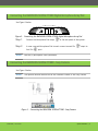
1
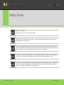
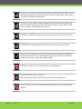
SCOPIA XT1000 User Guide Version 1.0 Notice © 2000-2009 RADVISION Ltd. All intellectual property rights in this publication are owned by RADVISION Ltd and are protected by United States copyright laws, other applicable copyright laws and international treaty provisions. RADVISION Ltd retains all rights not expressly granted. This publication is RADVISION confidential. No part of this publication may be reproduced in any form whatsoever or used to make any derivative work without prior written approval by RADVISION Ltd. No representation of warranties for fitness for any purpose other than what is specifically mentioned in this guide is made either by RADVISION Ltd or its agents. RADVISION Ltd reserves the right to revise this publication and make changes without obligation to notify any person of such revisions or changes. RADVISION Ltd may make improvements or changes in the product(s) and/or the program(s) described in this documentation at any time. If there is any software on removable media described in this publication, it is furnished under a license agreement included with the product as a separate document. If you are unable to locate a copy, please contact RADVISION Ltd and a copy will be provided to you. Unless otherwise indicated, RADVISION registered trademarks are registered in the United States and other territories. All registered trademarks recognized. For further information contact RADVISION or your local distributor or reseller. RADVISION SCOPIA XT1000 User Guide, June 2010 http://www.radvision.com RADVISION | User Guide Notice | 2 Table of Contents Notice ......................................................................................................... 2 Safety Rules .................................................................................................. 5 Warnings ................................................................................................... 7 Cleaning .................................................................................................... 8 Environmental Safety .................................................................................... 8 Safety Rules for Batteries ............................................................................... 9 En 55022 Class A Compliance ......................................................................... 10 FCC 15 Class A Compliance ............................................................................ 10 CE Mark ................................................................................................... 10 About SCOPIA XT1000...................................................................................... 11 Preliminary ............................................................................................... 11 General Introduction ................................................................................... 11 Features at a Glance ................................................................................... 12 SCOPIA XT1000 Components ........................................................................... 12 Videoconference Tips .................................................................................. 13 Updates and Detailed Information ................................................................... 14 System Installation ......................................................................................... 15 System Cabling........................................................................................... 15 Connecting the RADVISION SCOPIA XT1000 Digital Microphone Array Pod .................... 17 Connecting the RADVISION SCOPIA XT1000 - Sony Camera ...................................... 17 Remote Control .......................................................................................... 18 RADVISION | User Guide Table of Contents | 3 About the Graphical User Interface (GUI) ............................................................. 22 Elements Composing a Page ........................................................................... 22 How To Select a Page .................................................................................. 24 Function Key Usage ..................................................................................... 24 Menu Structure .......................................................................................... 25 First Time Equipment is Switched On .................................................................. 26 ONE Monitor Configuration ............................................................................ 26 TWO Monitors Configuration .......................................................................... 27 Product Registration .................................................................................... 27 Quick Setup .............................................................................................. 27 Call Management ........................................................................................... 32 How To Make a Call ..................................................................................... 32 Direct Call ................................................................................................ 32 Last Calls.................................................................................................. 33 How To Make a Call from Phonebook ................................................................ 34 How To Disconnect a Call .............................................................................. 35 How To Add Participants to a Conference (Optional) ............................................ 35 Secure Connections ..................................................................................... 36 How To Receive a Call .................................................................................. 36 Presentation.............................................................................................. 36 Phonebook ................................................................................................ 37 Audio-Video Management .............................................................................. 39 System Configuration Settings ........................................................................... 42 User Settings ............................................................................................. 42 Administrator Settings .................................................................................. 44 Technical Specifications .................................................................................. 59 RADVISION | User Guide Table of Contents | 4 Safety Rules DEVICE IN CLASS I Always connect to a grounded socket. CAUTION: for the operator's safety, only use the mains adapter that has been provided with the device. CAUTION: the mains cable is used as a disconnecting device, use therefore an easily accessible outlet located near the device for the power supply connection. Never remove the mains plug while the device is connected. CAUTION: connect the LAN port to an internal LAN circuit only. It is absolutely forbidden to connect the system to an outdoor telecommunication line. CAUTION: the Microphone Pod cable provided with the system must be used only with this system and must not be routed under carpets, through walls, within risers, or as part of building wiring systems. RADVISION | User Guide Safety Rules | 5 CAUTION: the ETHERNET cable provided with the system must be used only with this system and must not be routed under carpets, through walls, within risers, or as part of building wiring systems. CAUTION: the HD-CAMERA cable provided with the system must be used only with this system and must not be routed under carpets, through walls, within risers, or as part of building wiring systems. CAUTION: the OUTPUT connector provides a Limited Power Sources DC output. CAUTION: This equipment will be inoperable when the mains power fails. CAUTION: the change from cold to hot environments can cause condensate to form inside the device. To avoid malfunctioning, wait at least 2 hours before connecting the device to the main power supply. CAUTION: in case of fire, do NOT use water to extinguish it. CAUTION: RISK OF ELECTRIC SHOCK The power supply used by this device involves lethal voltage levels. CAUTION: do not touch the internal parts of the device (and/or of the mains adapter). RADVISION | User Guide Safety Rules | 6 CAUTION: if objects or liquids leak into the device, disconnect the power supply cable IMMEDIATELY. Have it checked by an authorized technician before using the device again. CAUTION: contact an authorized technician/consultant for assistance. CAUTION: when making repairs, disconnect the device from the power supply. Warnings Many of the components used in this device are sensitive to electrostatic charge. When handling the connection cables, disconnect the power supply and avoid direct contact with the connector terminals. When handling electronic components, touch a grounded surface to eliminate any static electricity. If possible, wear a grounding arm band. Failure to comply with these warnings could cause permanent damage to this device. RADVISION | User Guide Safety Rules | 7 Cleaning To clean the device use a dry soft cloth (or with a little bit of gentle detergent). Never use solvents, such as alcohol or gasoline, to avoid damaging the finish. Environmental Safety This equipment must not be treated as household waste and should instead be handed over to the applicable collection point for the recycling of electrical and electronic equipment. With the correct disposal of this equipment, you will help prevent any potential negative consequences for the environment and human health, which could otherwise be caused by inappropriate handling of this product. For more detailed information about recycling this product, please contact your local city office, your household waste disposal company or the dealer where you purchased this product. RADVISION | User Guide Safety Rules | 8 Safety Rules for Batteries RADVISION | User Guide Risk of explosion if batteries are replaced by an incorrect battery type. Dispose of used batteries following the user instructions. The batteries of this equipment must be disposed of by either a recycling company or a company qualified for the disposal of dangerous materials. The battery may also be disposed of in special recycling containers specifically for worn out battery (this may vary from country to country). Only use the same type of battery that was originally provided with the equipment. Replace the batteries when the remaining power charge significantly low. Do not recharge. Do not use any damaged batteries. Do not to use the batteries for different reasons from those prescribed. Do not short circuit the batteries (direct contact between + and – poles of the battery). This can happen accidentally during the maintenance of the equipment or the replacement of the worn out batteries. Do not put the batteries close to flames, sparks, radiators, microwave ovens, fireplaces, direct sun light or other sources of heat. Do not throw the batteries into the fire. Do not weld directly on the battery terminals. Do not install the batteries with the polarity upside down. Please refer to the installation instructions for battery installation. Do not damage the batteries in any way. Do not try to open or to pierce the batteries. Avoid any accidental collision as it could cause the batteries to rupture and leak corrosive liquids or irritable vapors. In such case disconnect the power immediately from the equipment and batteries. In case the battery liquids comes into contact with your skin or garments, wash the area immediately with water. If it comes into contact with your eyes, wash immediately with plenty of water and contact either a doctor or the nearest first aid office immediately. Keep away from the children’s reach. Safety Rules | 9 En 55022 Class A Compliance This is a Class A product. In a residential environment this product may cause radio interference. In such case the user may need to take adequate measures. FCC 15 Class A Compliance This equipment has been tested and found to comply with the limits for a Class A digital device, pursuant to part 15 of the FCC Rules. These limits are designed to provide reasonable protection against harmful interference when the equipment is operated in a commercial environment. This equipment generates, uses and can radiate radio frequency energy and, if not installed and used in accordance with the instructions manual, may cause harmful interference to radio communications. Operation of this equipment in a residential area is likely to cause harmful interference in which case the user will be required to correct the interference at his own expense. CE Mark RADVISION Ltd. hereby declares that this device complies with essential requirements and other relevant notes of R&TTE Directive 1999/5/EC. RADVISION | User Guide Safety Rules | 10 About SCOPIA XT1000 Preliminary The system supports the complete functionality and all associated configurations that are described in this guide. Some functionalities, being optional, need to be activated by a license. General Introduction SCOPIA XT1000 is the enhanced HD video communication system with top of the range performances and an elegant Italian design by Paolo Villa Design visible in each detail: from set-top to the customized camera, from Graphical User Interface to the new remote control. The high experience of RADVISION and the focus on innovation make SCOPIA XT1000 a perfect system to maximize HD video communication. It is suitable for videoconference sessions in medium and large video conferencing rooms. Very high usability of the Graphical User Interface – SCOPIA XT1000 features: several transparency levels for menu and information, video images in full screen, colored buttons to access the most used functions. Everything was designed to make SCOPIA XT1000 very easy to use. Highest performances and excellent quality - Video resolution up to 1920x1080 (1080p), excellent audio quality with unique 20 kHz G.719 audio coding, graphic resolution up to 1920x1200 (WUXGA) make SCOPIA XT1000 the professional system for the best HD video communication. RADVISION | User Guide About SCOPIA XT1000 | 11 Refined design in each detail - Each detail is carefully studied for a pleasant and refined video communication experience. Modularity and expandability - The basic system features a video resolution up to 1080p30. Many options can be added to reach the top technical level: MCU up to 4 or 9 sites, bandwidth up to 12 Mbps. Features at a Glance 2 HDMI input and 2 HDMI output audio/video ports. DVI-I port. SPDIF input and output audio ports. Automatic support for Dual Monitor. Support for IP-H.323, IP-SIP. Full-duplex audio with echo cancellation. Automatic Noise Suppression. Mixed mode HD MCU with dial-out/dial-in configuration. Support for AMX™ and Crestron™ protocols. WEB remote management, configuration and diagnostics. 2 USB ports (for future use). SCOPIA XT1000 Components Main components of the SCOPIA XT1000 are: RADVISION SCOPIA XT1000 - Codec Unit; RADVISION SCOPIA XT1000 – Standard Camera, or alternatively the RADVISION SCOPIA XT1000 – Sony Camera; RADVISION SCOPIA XT1000 Digital Microphone Array Pod; RADVISION SCOPIA XT1000 Remote Control Unit with batteries; Power supplier with cable; Cables for connection to monitor, camera, LAN network, personal computer; RADVISION | User Guide About SCOPIA XT1000 | 12 Mechanical kit for Codec Unit vertical placement; User guide; Quick setup guide. Note: The peripherals visible in the wiring system (see relevant chapter) that are not included in the above list are shown as examples only. Videoconference Tips Read these tips to improve a virtual meeting, to optimize audio-video transmission and reception, and to fully enjoy all videoconference benefits. Optimal Meetings Before starting a videoconference, be sure that all you need is ready: addresses or numbers to call, lighting, Microphone Pods. Connect and test all peripherals eventually needed (additional HD camera, DVD player or recorder, PC/laptop). Use natural gestures as in a real meeting. Speak in your normal voice. Optimal Video Avoid contemporaneous usage of natural (changing) and artificial lighting. Avoid direct artificial lighting. Avoid “mobile” backgrounds (curtains moved by the wind). Try to fill the screen as much as possible with persons, not backgrounds. Optimal Audio Place the Microphone Pod on the table in front of people (use 2 Microphone Pods in case of big tables). RADVISION | User Guide About SCOPIA XT1000 | 13 Do not place papers or other objects in front of the Microphone Pod. Don’t rustle papers or tap on the table or Microphone Pod. Mute the Microphone Pod before moving it. Speak in your normal voice. Updates and Detailed Information To verify the availability of manual updates or for more information about video conferencing, please visit www.radvision.com RADVISION | User Guide About SCOPIA XT1000 | 14 System Installation System Cabling See Figure 1, System Cabling Diagram for examples of possible connections. Attention All operations must be carried out without connection to main power supply. Step 1 Verify the contents of the delivery you received. Step 2 Plan the installation of the system in the desired location. Step 3 Connect the Standard Camera. The connection of the Sony Camera is the same as the Standard Camera. Step 4 Connect the Microphone Pod. Step 5 Connect the HD video cable to the HD1 monitor output. Step 6 Connect the LAN or GLAN input to the network. Step 7 Connect supplementary audio or video equipments to the available inputs/outputs. Step 8 Connect the power supply. RADVISION | User Guide System Installation | 15 Step 9 Switch the monitor on. Step 10 Press the Power button on the back of the Codec Unit. The system status LED on the front means: Step 11 LED on: System is on and normally operating. LED flashing: System power is on, but the system is in standby mode. LED off: System power is either off or not connected. Wait for the main user interface to appear. Figure 1. System Cabling Diagram RADVISION | User Guide System Installation | 16 Connecting the RADVISION SCOPIA XT1000 Digital Microphone Array Pod See Figure 2 below. Figure 2. Connecting the RADVISION SCOPIA XT1000 Digital Microphone Array Pod Step 1 Connect the Microphone Pod output Step 2 In case a second Microphone Pod is used: connect second Pod first Pod Note: to the rear panel of the system. output to input. Use two (2) Microphone Pods (maximum). Connecting the RADVISION SCOPIA XT1000 - Sony Camera See Figure 3 below. Note: The optional second camera can be the Standard Camera or the Sony Camera. Figure 3. Connecting the RADVISION SCOPIA XT1000 - Sony Camera RADVISION | User Guide System Installation | 17 Remote Control Attention You can manage all system functions using the remote control. Remote Control Keys Key Name ON/OFF RADVISION | User Guide Function Switch on/off. Enable screensaver mode. ALPHANUMERICS CHARACTERS Enter letters and numbers. PHONEBOOK Open the phonebook. CALL Place a Call. DISCONNECT Disconnect a call. ARROW Navigate through menus, move the camera. System Installation | 18 Key Name C RADVISION | User Guide Function In the main screen or in a Call, hide the graphics. Delete the last introduced alphanumeric character. BACK Come back to previous page. PRESENTATION Presentation activation/deactivation. FUNCTION Context sensitive keys. VOLUME Increase/decrease audio level. MUTE Enable/disable the audio transmission. PRIVACY Send/stop sending video privacy image to remote. System Installation | 19 Key Name Function ZOOM Zoom in/out the current local or remote camera. layouts Exchange the video images between monitors. pip Activate/deactivate PIP and PaP windows. inputs Select video input. help RADVISION | User Guide Activate/deactivate on line help. In a call, display call diagnostics. far Select the remote camera control. near Select the local camera control. preset - select preset - memo Select camera presets. Store camera presets. System Installation | 20 Insertion of Characters in the Alphanumeric Fields For number or letter insertion use the alphanumeric keyboard of the remote control or, alternatively, the virtual keyboard by pressing the OK key once the cursor is positioned in the alphanumeric field. Change the input mode by pressing OK in the input field. Available modes are abc1 (letters, then digit) 1abc (first digit, then letters) 123 (digits only) Virtual keyboard Select the BACK key on the remote control to close the virtual keyboard. Remote Control Batteries The remote control uses 2 (two) LR2055 batteries. An alert appears on the system information area when batteries are low. Change the batteries by opening the cover on the back of the remote control. RADVISION | User Guide System Installation | 21 About the Graphical User Interface (GUI) All system configurations and functionalities can be activated inside the GUI shown on the monitor. Elements Composing a Page System information area Local information area RADVISION | User Guide Button area Function key area About the Graphical User Interface (GUI) | 22 Page – any page inside the GUI. Home page – main GUI page; from here you can access all system functionalities and/or configurations. Button area – displayed in all pages right end, with the selectable page entries Function key area – the graphic horizontal bar displayed in all pages lower end, with the active remote control function keys System information area – the graphic horizontal bar displayed in the upper end, with status information Local information area – the graphic horizontal bar displayed upon the function key area, with system information Some pages have a preview area, showing next (nested) pages to make the navigation easier. RADVISION | User Guide About the Graphical User Interface (GUI) | 23 Finally, a content area showing data. How To Select a Page Use arrow keys on the remote to move through, orange frame showing the selection. To enter the page, press OK. Function Key Usage Use arrow keys on the remote to move through the button area controls and select command to perform (e.g. Make a call or Settings). According to the selected action, function key area buttons dynamically change showing further possibilities connected to the action. In this way, by pressing on the remote arrows keys and function keys only, you can access all system functionalities. For example, when selecting Make a call remote function keys show Recent calls, Direct call and Contacts, to indicate possibility to make a call by means of the last calls list, or directly inserting the number to be called or making a call from the phonebook. When selecting Settings, remote function keys allow to select Administrator settings, User settings, or Quick setup. RADVISION | User Guide About the Graphical User Interface (GUI) | 24 Menu Structure Preferences Call Options User Diagnostics Load Default Values Date-time System Location Call LDAP Settings Preferences Home Calls Cameras Video Quality Encryption Options Cameras Monitors I/0 Connections Audio-Inputs Administrator Audio-Outputs Preferences Networks GLAN LAN SIP Protocols H323 Password Remote access Utilities Licenses Load default values RADVISION | User Guide About the Graphical User Interface (GUI) | 25 First Time Equipment is Switched On You can connect to the system one monitor (to the HD1 Output), or two (one to the HD1 Output, one to the HD2 Output). In any case the system is able to automatically recognize the output configuration, and properly working. To change default settings, see the I/O Connections section. ONE Monitor Configuration When not connected, you’ll see the GUI overlapped to the local camera image. Once in connection, you’ll see two overlapped images: the remote image in full-screen format, and the local image in a smaller overlapped window (PIP, Picture In Picture). By pressing the layouts key on the remote control, you can swap the contents of the windows: you’ll see the local image in full-screen format, and the remote image in a smaller overlapped window. By pressing the pip key, you can change the visualization to two windows of the same size (PaP, Picture and Picture) or remove the second window. If the remote sends you a presentation, you’ll see it in full-screen format, with the remote image in a smaller overlapped window. By pressing in sequence the layouts key on the remote control you can change the contents of the windows, choosing to see the presentation, remote video or local video as the full-screen content. The pip key on the remote control acts as before. RADVISION | User Guide First Time Equipment is Switched On | 26 TWO Monitors Configuration When not connected, you’ll see the local camera image on the auxiliary monitor, and the GUI overlapped to the local image on the main monitor; once in connection, you’ll see the remote image on the main monitor, and the local image on the auxiliary monitor. Note: The main monitor is connected to HD1. The auxiliary monitor is connected to HD2. If the remote sends you a presentation, you’ll see it on the main monitor, and the remote image on the auxiliary monitor. Product Registration Step 1 Open the envelope that came with the SCOPIA XT1000. Step 2 Locate the serial number and product key. Step 3 On a computer, open a browser and navigate to http://www.radvision.com/XT1000. Step 4 Complete the online registration form and enter the serial number and product key. The web registration form returns a license key. Step 5 Write down the license key and keep it in a safe place for future use. Quick Setup A quick setup wizard will assist you in this first approach to the system. The quick setup will show more pages, allowing user to set some useful parameters for basic system management. RADVISION | User Guide First Time Equipment is Switched On | 27 Country and Language of Interface Graphics and Image Setup Certain types of monitors could cut the image on edges, and in this case the test orange frame could be not fully visible. To properly see all the graphic elements, you might be prompted to perform a setup. RADVISION | User Guide First Time Equipment is Switched On | 28 Date and Time Setup Note: RADVISION | User Guide Enable NTP - the NTP server (Network Time Protocol) allows you to synchronize your system clock to the clock in the network, allowing you to align with precision devices connected on the Internet. First Time Equipment is Switched On | 29 Codec Unit Display Name Network Settings Attention RADVISION | User Guide To set these parameters correctly, please contact your network administrator. First Time Equipment is Switched On | 30 Moving the Camera Step 1 On the general screen, navigate to Cameras using the arrow keys. Step 2 Select Move camera. Step 3 Use the arrow keys to move the camera to the preferred position. Step 4 Select Stop moving camera. Step 5 Repeat the procedure if you have an optional second camera installed. RADVISION | User Guide First Time Equipment is Switched On | 31 Call Management This section of the guide explains the basic functionality of the system. It is assumed that the system is correctly installed. How To Make a Call Once the system is on, the main user interface will display the home page. A call can be made in three different ways: Direct call – inserting the number/address to call, see Direct Call. Recent calls – reselecting an already called/incoming number, see Recent Calls. From the Phonebook – see How To Make a Call from Phonebook. Direct Call To place a Direct call: Step 1 From the home page, select Make your call in the button area. Step 2 You will enter the Direct call page for address/number input. Step 3 Press the CALL key RADVISION | User Guide or the dedicated function key on the remote control. Call Management | 32 Attention A virtual keyboard can be activated if you need to enter text (e.g., aliases for calls). To change the input mode, see Insertion of Characters in the Alphanumeric Fields. To activate it, simply press OK with the cursor in the input area. Then select the desired letter on the virtual keyboard by moving the cursor over it, and press OK. Call Options In the Direct call page you can insert number/address to call. Once in the dedicated area, by pressing the OK key on the remote control you can change characters mode insertion (available choices being alphanumeric with alpha first, alphanumeric with numbers first, numbers only), or access the virtual keyboard. Press the C key on the remote control to erase the last inserted character. Moreover, it is possible to set some communication parameters: Basic options – Call profiles, that is H.323 or SIP Advanced options – Call profiles, Rate (K), Call type. Call profiles, that is H.323 or SIP. Rate (K) to select the actual rate for the call. Call type to select Audio-Video or Audio only calls. Last Calls To make a Reselection: Step 1 From the home page, select Make your call in the button area. Step 2 Select Last calls by pressing the dedicated function key on the remote control, Step 3 A list will appear, and numbers can be selected and/or modified. A cyclic buffer of 25 numbers is available to store calls. RADVISION | User Guide Call Management | 33 The arrows that appear on the call number side show: Incoming call Outgoing call Lost incoming call How To Make a Call from Phonebook To enable the quick selection of a number to call, a phonebook is available to store data about terminals that are frequently called. In particular, up to 1000 contacts may be inserted, each contact being characterized by up to 100 terminals. To call one of these numbers, users need only select the entry in a list. To place a Call from the Phonebook: Step 1 From the home page, select Make your call in the button area. Step 2 Then select Contacts, by pressing the dedicated function key on the remote control. Step 3 Select the desired name. Step 4 Press the CALL Note: key or the dedicated function key on the remote control. In the Server menu choose among the local phonebook, or one of the remote LDAP servers configured in the Phonebook Configuration page (see Phonebook section). The remote control has a dedicated key to directly open the phonebook. See the Remote Control section. RADVISION | User Guide Call Management | 34 How To Disconnect a Call Once the call is on, you can: Disconnect by pressing the DISCONNECT Select Disconnect in the button area, then select Disconnect by pressing the dedicated function key on the remote control. remote control key. How To Add Participants to a Conference (Optional) Systems provided by optional MCU (Multi Conference Unit) license can manage conferences with more than two participants. Once the first connection is on, you can: Add a participant by pressing the CALL key on the remote control Select Add site in the button area: the same options as for placing the first call are available Accept an incoming call Once the Multi Conference is on, you can: Disconnect a terminal in conference by pressing the DISCONNECT key on the remote control or selecting Disconnect in the button area, then pressing the dedicated function key on the remote control (Disconnect), and selecting it in the connected terminals list Disconnect all terminals in conference by pressing the DISCONNECT key on the remote control or selecting Disconnect in the button area, then pressing the dedicated function key on the remote control (Disconnect all). Change the video layout selecting Video layout or Default layout by pressing the dedicated function keys on the remote control Take control over the conference by selecting Conference in the button area. RADVISION | User Guide Call Management | 35 Secure Connections The system can manage secure videoconference sessions via encrypted connections, in both point-to-point and multipoint sessions. The multipoint session supports up to three remote encrypted participants. To do this, the encryption function must be enabled: for more information, refer to the Encryption section of this guide. Once encryption is properly configured, you can make a secure call by following the same procedure described for a standard call. Useful Information The encryption status can be checked on the local information area. If the encryption is enabled and configured, an icon showing a padlock is displayed; the padlock icon meanings are: Encryption has been enabled but the function is not active. Encryption is active. Encryption is activated in transmission only. How To Receive a Call If you receive a call and the automatic answer function is not enabled, or you are in a configuration page, a notification will be displayed and you will be prompted whether or not to accept the call. Presentation Once a call has been established, you can send to the remote terminal a second video stream with the PC content (obviously having a PC connected to the DVI system input): to do this, simply press the Presentation key on the remote control. RADVISION | User Guide Call Management | 36 To close the presentation, simply press again the Presentation key. Important Presentation mode must be supported by the remote terminal too; if not, system will automatically send the PC content instead of the live camera video. You can start presentation without being in connection: in this case you’ll see your presentation; if a call will be started, system will automatically enter Presentation mode, that is live camera video + Presentation. Phonebook Entering Names in the Phonebook From the home page, select Make your call in the button area, then select Contacts, by pressing the dedicated function key on the remote control, or press the PHONEBOOK remote control key. Four choices are available: Call Add contact Modify contact Delete contact By selecting Add contact, the following page will be displayed: RADVISION | User Guide Call Management | 37 Up to 1000 contacts may be inserted, each contact being characterized by up to 100 terminals. Step 1 Enter new contacts data in the phonebook by using the remote control; data insertion mode could be changed, available choices being alphanumeric with alpha first, alphanumeric with numbers first, numbers only, or access the virtual keyboard. Press the C key on the remote control to erase the last inserted character. Step 2 Enter Surname, Name and Company. Step 3 Enter terminal (or terminals, since one contact may be associated to more terminals) data: name, number (or alias), call type (H.323, SIP). Modifying Phonebook Entries To modify a phonebook entry: Step 1 Select the desired entry Step 2 Select Modify contact, by pressing the dedicated function key on the remote control Step 3 Enter modifications and save them. Erasing Phonebook Entries To erase an entry in the phonebook: Step 1 Select the desired entry. Step 2 Select Delete contact, by pressing the dedicated function key on the remote control (the system will ask you to confirm deletion). RADVISION | User Guide Call Management | 38 Audio-Video Management Video Input Management From the home page, select Cameras; by pressing the RED function key on the remote control you can move the camera, while pressing the other function keys you can select different inputs. By pressing the remote control key OK you can toggle between different inputs (the same function can be achieved by pressing the remote control key Inputs). Note: The desired video source must be connected to the system inputs on the back of the equipment beforehand. For a correct setup of the function keys, see I/O Connections section, Camera section. During a connection it is also possible to control not only the local video camera’s zoom and panning functions but also those of the remote camera (if enabled). Use the remote control keys Far and Near to select remote or local camera. Using DVI-I IN In the system rear panel there is a DVI-I input to connect a personal computer. For a correct cabling, see the cabling diagram. Correct use of the DVI-I implies that the video PC configuration has been set (setting: screen properties) with one of the following picture frequency limits (or refresh frequencies). Resolution Refresh Frequency (Hz) 640 x 480 60, 72, 75, 85 800 x 600 56, 60, 72, 75, 85 1024 x 768 60, 70, 72, 75, 85 1280 x 768 60, 75 1280 x 1024 60, 67, 70, 72, 75, 76, 85 1440 x 900 60 1600 x 1200 60 1920 x 1200 60 RADVISION | User Guide Call Management | 39 Note: You can also connect a camera to the DVI-I input, but it will be managed as PC content. Video Privacy To activate the Video Privacy function, press the PRIVACY key on the remote control. Local video will no longer be transmitted, and a predefined image will be sent. The icon will appear in the system information area indicating that the remote terminal is no longer receiving video from local terminal. To transmit the local video again, press the PRIVACY key. Note: To have the Video Privacy function active at the system startup, see User Settings section. Do Not Disturb From the home page, select Options; by pressing the RED function key on the remote control you can activate the Do Not disturb function, that is the system does not answer to incoming calls (busy for the remote). The icon will appear in the system information area. Note: To have the Do Not Disturb function active at the system startup, see User Settings section. Controlling Audio The VOLUME keys allow you to adjust the level of received audio. By pressing the MUTE key you can activate the mute function, that is local audio will no longer be transmitted. On the local display, the icon will appear, indicating that the mute function is active. The icon terminal. RADVISION | User Guide on the local display will indicate that the mute function is active in the remote Call Management | 40 Video Camera Presets The Preset function allows the user to save camera positions (up to a maximum of 99 positions) to enable quick selection of a certain camera frame. To save a preset: Step 1 Set the desired camera position and adjust the video zoom. Step 2 Press the MEMO key on the remote control followed by a memory location (from 01 to 99); during the operation the system does not give you any feedback, but at the end a message will appear notifying the stored position. To recall a memory location: Step 1 Press the SEL remote control key Step 2 Enter the memory location number corresponding to the desired preset. RADVISION | User Guide Call Management | 41 System Configuration Settings This section describes the procedures to properly configure the system. Important Some configuration parameters have been set the first time the system was switched on; some other can be applied only when no connection is active. From the home page select Settings. Three choices are available: User settings– press the YELLOW function key on the remote control. Administrator settings – press the RED function key on the remote control. Quick Setup – press the BLUE function key on the remote control to come back to the setup wizard. User Settings User Preferences This menu contains the following configuration settings: Language to set the interface language. Automatic screensaver to enable screensaver function (with its activation time). Remote control code. The remote control has a code (01 by default) that can be RADVISION | User Guide System Configuration Settings | 42 changed to control with one remote control more systems in the same room avoiding interferences. To do this, you must change the code inside the system (in this menu), and then accordingly change the remote control code by pressing simultaneously the RED and GREEN function keys on the remote control. The ON/OFF function key on the remote control will become red, and you can insert the remote control code (two characters from 01 to 99). Call-Answer Mode This menu contains the following configuration settings: Mute - Selected, at the start-up and after each disconnection system will not transmit audio, an icon will be displayed in the local and remote terminals. Do Not Disturb - Selected, at the start-up and after each disconnection system will not accept incoming calls (system busy for the caller), an icon will be displayed in the local terminal. Video Privacy - selected, at the start-up and after each disconnection system will no longer transmit local video, and a predefined image will be sent; an icon will be displayed in the local terminal. Confirm disconnection - Enable/disable confirmation requests for call disconnection. Automatic answer: - Enable/disable the automatic answer function, after the selected number of rings. You may choose to enable the automatic answer always, never or never if another call is already in place. Ringing Volume - To set the ringing volume. Volume - To set the default system audio volume. Diagnostics This menu allows getting information about: Software version: all information about software modules. Audio I/O: all information useful to establish whether Audio interfaces are properly working, including two tests (local tone generation, local tone transmission to remote). Note: RADVISION | User Guide To access diagnostics information about the calls, press the help key on the remote control. System Configuration Settings | 43 Load Default Values To restore all default values for user settings, you will be asked for confirmation. Administrator Settings You need a password to access the administrator settings. The default password is 1234. You may change the password in Administrator settings->Utilities ->Password. Note: Some settings have already been covered in the Quick Setup section, because they belong to the minimal required set necessary to have system properly working. In any case they can be modified in this menu. System This menu contains the following configuration settings: Date – time Location LDAP Date - Time Use this menu to directly set date and time values, or to enable and configure NTP server (internet Time). Note: RADVISION | User Guide The NTP server (Network Time Protocol) allows you to synchronize your system clock to the clock in the network, allowing you to align with precision devices connected on the Internet. System Configuration Settings | 44 Location Use this menu to set regional data for the terminal: System name that will appear either in local, either on remote when connected Country Language Audio Coding Selection Tone Video Frequency, to set video refresh frequency Note: Once you select the Country, the other fields are automatically filled. LDAP Use this menu to set LDAP server address. As phonebook you can use a local, or a remote one. In this case, by selecting the Add server key you can access a menu to set: Server type Server address Used port (389 by default) User Password Base Filter By selecting the Modify server key you can modify parameters related to an already present link to a server. By selecting the Delete server key, you can delete a stored link to a remote server. Note: RADVISION | User Guide The LDAP server parameters must be requested to LDAP server administrator. System Configuration Settings | 45 Calls This menu contains the following configuration settings: Preferences Video Quality Encryption Preferences In this menu you can configure a set of parameters the system will use in transmission (obviously always taking into account the remote terminal capabilities): General Audio Video H.323 General In this menu you can configure: The maximum Rate for a call. The system will use the selected rate for all incoming or outgoing calls. Audio coding - the preferred Audio Coding for a call, that is the one the system will try to use for all incoming or outgoing calls, if supported by remote system too Video coding - the preferred Video Coding for a call, that is the one the system will try to use for all incoming or outgoing calls, if supported by remote system too. Audio In this menu you can configure a set of various functionalities that can be enabled/disabled, to make the system compatible with older systems. RADVISION | User Guide System Configuration Settings | 46 Video In this menu you can configure a set of various functionalities that you can enable/disable, to make the system compatible with older systems. H.323 In this menu you can configure: DTMF RFC2833 (H.323) to choose this mode of DTMF transmission as different alternative to in band transmission RTP Firewall enable a function that increases system security rejecting RTP packets not “rightful” for the current call Select dialing number format mode Separator, to choose the desired separator for call through a gatekeeper Video Quality In this menu you can configure some parameters related to video quality: Error resilience – In case of packet loss (due for example to network congestion) allows minimizing error, so making the codec much “stronger”. Flow Control – A Flow Control (bandwidth reduction) request is sent to the remote terminal, in case of packet loss. Error strategies – To set the number of allowed line errors before video is frozen: Min Fluency - Freezes video frames at the first occurred error, Max Fluency - Never freezes video frames, and allows errors through Automatic Lip Sync – You can also synchronize audio with video. The audio delay represents the value in milliseconds by which received audio is delayed. To have perfect synchronization between audio and video, you must adjust these parameters according to the connection type. By selecting the check box (strongly recommended option), you allow the system to perform this operation automatically. Alternatively, you can make manual adjustments by moving the slider along the bar until you obtain the best synchronization. RADVISION | User Guide System Configuration Settings | 47 Sharpness - Force use of high resolution formats at lower connection rates. Video fluency can be affected. Encryption In this menu you can configure: Accept protected calls – If encryption is not enabled, the system can in any case accept encrypted incoming calls Enable Encryption – If encryption is activated, the system will use encryption in H.323. Unprotected calls – from this menu you can choose the policy the system will apply if the remote terminal is not able to support protected calls. Disconnect – The system will not allow connection with a remote terminal that does not support encryption, and therefore automatically disconnects. Ask Confirmation – During the session negotiation phase, the system will ask you to confirm that you want to establish an unprotected call. Inform – The system will inform you that you are about to establish an unprotected connection by displaying a visual warning message. Show Status – The system will notify you that you are about to establish an unprotected call, and once the connection is established an open padlock symbol will be displayed on the local information area. Length of AES Key The AES key length is set to 128 bits. Note: For an IP connection, the key length is always 128 bits. Length of Prime DH Number The encryption protocol requires the simultaneous exchange of a prime number and an AES private key between terminals. The prime number length is set to High Security (length 1024 bits). Note: RADVISION | User Guide For IP calls, the system always uses the High Security option with a 1024-bit length. Most common video communication terminals normally use the High Security prime number length and the 128-bit AES private key. System Configuration Settings | 48 I/O Connections This menu contains the following configuration settings: Cameras Monitor Audio-Inputs Audio-Outputs Cameras This menu contains the following configuration settings: General HD1 HD2 DVI General In this menu you can: Set the default camera Set the correct driver for VISCA control Enable/disable remote control of the camera (if available) Enable/disable “bring back to place” function (system stores camera position when turned off), if available RADVISION | User Guide System Configuration Settings | 49 HD1 In this menu you can: Define whether the camera supports PTZ Give it a name Set white balance mode (in case of lighting problems, it is possible to choose appropriate white balancing mode) HD2 In this menu you can: Define whether the camera supports PTZ Give it a name Set white balance mode (in case of lighting problems, it is possible to choose appropriate white balancing mode) DVI In this menu you can: Enable this input Give it a name Set contrast, brightness, color Auto Adjust, to have the incoming image correctly displayed (in case of graphic problems) Reset, in case of problems when connecting a PC to the system Note: RADVISION | User Guide A camera can also be connected to the DVI-I input, but it will be managed as PC content. System Configuration Settings | 50 Monitor This menu contains the following configuration settings: General Graphic adjustment PIP – PaP General In this menu you can: Set output configuration (auto, 1 monitor, 2 monitors) Set the Resolution for HD1 output (auto, 1080p, 720p) Set the Resolution for HD2 output (auto, 1080p, 720p) Reset HD1 or HD2 monitors if you experience flickering problems or missing audio output from the monitor Graphic Adjustment Make setting operations to adjust the image on edges cut by some kind of monitors (same operation as described in the Quick Setup section). PIP - PaP In this menu you can set options connected to PIP (Picture In Picture) and PaP (Picture and Picture) functions. The PIP function allows seeing two overlapped images in one monitor, that is remote image in full-screen format, and local image in a smaller overlapped window. The PaP function is a Dual Monitor emulation on the main output. It allows to see in one monitor two windows side by side, with local and remote images. PIP – position, to set the default PIP position PIP – rotation, to enable/disable rotation, and its direction (rotation being controlled by pip function key on the remote control RADVISION | User Guide System Configuration Settings | 51 MultiImage Type Select AUTO to enable both PIP and PaP functions. Switch between PIP and PaP by pressing the pip function key. Select PIP to enable the PIP function. Select PaP to enable the PaP function. MultiImage Mode By selecting AUTO, PIP and PaP functions are enabled only when needed, that is when number of video flows is greater than available monitors number, and automatically place video flows (with precedence to remote ones). By selecting ON, PIP and PaP functions are enabled if at least two video flows are available (in case of unique video flow you have a full screen image, e.g. when system is not connected). By selecting OFF, PIP and PaP functions are disabled. Audio - Inputs This menu contains the following configuration settings: POD1 POD2 SPDIF/HDMI Echo Canceller POD1 In this menu you can: Enable/disable this input Set the gain for this input Enable/disable the echo canceller for this input RADVISION | User Guide System Configuration Settings | 52 POD2 In this menu you can: Enable/disable this input Set the gain for this input Enable/disable the echo canceller for this input SPDIF/HDMI In this menu you can decide how to manage this audio source, taking into account that you cannot have simultaneous use of SPDIF and HDMI. Enable/disable this input Set the gain for this input Set the usage mode, that is: Use SPDIF associated to DVI: when the DVI video input is selected, for example when a PC is connected, and an audio/video presentation is started on it Use SPDIF Use HDMI Echo Canceller In this menu you can: Enable/disable the AGC (the AGC effectively reduces the volume if the signal is strong and raises it when it is weaker) Enable/disable the Noise Reduction (the process of removing noise from the audio signal) RADVISION | User Guide System Configuration Settings | 53 Audio - Outputs In the General menu you can manage audio outputs: Listen SPDIF/HDMI input, to hear locally the audio input. Send HD-MON1/SPDIF to VCR, to send the transmitted audio to the output (to record the conference). Disabled by default, to avoid echo effects when a monitor is connected to MON1 (normal usage). Send remote received audio to VCR, to send to HD-MON1/SPDIF output the received audio. Networks This menu contains the following configuration settings: Preferences GLAN LAN Preferences This menu contains the following configuration settings: General Dynamic Ports NAT QoS General In this menu you can: Enable/Disable IPv6 support Set GLAN/LAN priority, that is the order used by the system to place outgoing calls RADVISION | User Guide System Configuration Settings | 54 Dynamic Ports In this menu you can set the range of Dynamic Ports for TCP and UDP, or leave in Auto detect mode. Note: When a firewall is crossed, the firewall administrator must open a range of dynamic TCP and UDP ports, as configured in the system, to allow bidirectional IP traffic. Moreover, once the ports have been opened, the protocols (TCP 1720 (Q.931), TCP 1503 (T.120), UDP 1719, and 1718 (RAS)) involved in a call must be taken into account. NAT In this menu you can: Enable/Disable NAT traversal Set NAT discovery mode Manual - user can set NAT IP public address HTTP autodiscovery - NAT discovery by means of HTTP server STUN autodiscovery - NAT discovery by means of STUN server Refresh time - opening time of pinhole inside NAT, also used as TTL by H.460 QoS In this menu you can Enable/Disable QoS, that is a means to offer the ability to provide different priority to different data flows, or to guarantee a certain level of performance to a data flow; in particular is possible to choose between Precedence/TOS and Differentiated Service. Precedence/TOS - For each flow (Audio, Video, Data, Signal) it is possible to define the Type Of Services and a Precedence to fit at best network capabilities. Differentiated Service - For each flow (Audio, Video, Data, Signal) it is possible to define a value to fit at best network capabilities. Note: RADVISION | User Guide Please contact your network administrator for correctly setting these parameters. System Configuration Settings | 55 GLAN The 10\100\1000 LAN interface, used by default. In this menu, you can enable automatic assignment of an IP address, or manually set: IP address Subnet mask Gateway IP address DNS server IP address You can enable and set bandwidth limitation. LAN The 10\100 LAN interface. In this menu, you can enable automatic assignment of an IP address, or manually set: IP address Subnet mask Gateway IP address DNS server IP address You can enable and set bandwidth limitation limits. Protocols This menu contains the following configuration settings: SIP H.323 SIP In this menu you can set: Terminal Alias - the name used by the terminal for registration to the server. Terminal password. RADVISION | User Guide System Configuration Settings | 56 Use registrar - run terminal registration at a SIP Registrar Server. Server - enter SIP Registrar Server IP address. Use Proxy - use a SIP Proxy Server. Server - enter SIP Proxy Server IP address. Server type - choose server type to connect to (e.g., CISCO UCM Microsoft LCS, etc.). Protocol type - use the appropriate protocol (UDP/TCP). Port - port for server signaling (default is 5060). H.323 In this menu you can set: Name H.323 (H.323 ID) - the name used by the terminal for registration to the gatekeeper. Number H.323 (E.164) - identifying number used by the terminal for registration to the gatekeeper. Refuse calls by IP address - Possibility to discard incoming calls by IP address, incoming calls by alias accepted only (if registered to a gatekeeper). Gatekeeper use and settings parameters. Utilities This menu contains the following configuration settings: Password Remote access Licenses Load default values RADVISION | User Guide System Configuration Settings | 57 Password In this menu you can set/change passwords for both User and Administrator. Remote Access In this menu you can: Enable the system being remotely controlled via WEB. Enable the system software to be remotely upgraded. Enable the system being remotely controlled by means of a proprietary protocol (AMX™ and Crestron™) via IP. Enable the system being remotely controlled via SNMP. Licenses In this menu you can insert software enabling licenses. Load Default Values In this menu you can restore all default values for administrator settings, or restore all Factory Defaults. RADVISION | User Guide System Configuration Settings | 58 Technical Specifications Supported Standards ITU-T H.323: IP networks IETF-SIP (RFC3261): IP networks Video : H.261, H.263, H.263+, H.263++, H.264 Audio : G.711, G.728 (option), G.729A, G.722, G.722.1, G.722.1 Annex C, G.719, MPEG4 AAC-LD Data: T.120 LDAP: H.350 Far End Camera Control (FECC): H.224, H.281 MCU compatibility: H.243, H.231 Transmission Bit rate: Point to point 64 kbps ÷ 4 Mbps over IP (H.323/SIP) 64 kbps ÷ 6 Mbps over IP (H.323/SIP) with rate extension software option MCU (software option) RADVISION | User Guide Technical Specifications | 59 64 kbps ÷ 6 Mbps over IP (H.323/SIP) 64 kbps ÷ 12 Mbps over IP (H.323/SIP) with rate extension software option Video Dual Video Stream H.239 Dual Video H.323 BFCP Dual Video SIP Support for resolution up to 1080p30 in both main stream and dual stream simultaneously Video resolution: 1920 x 1080@30fps: HD1080p30 1280 x 720@30fps: HD 720p30 1024 x 576@30fps: w576p 768 x 448@30fps: w448p 512 x 288@30fps: wCIF 352 x 288@30fps: CIF 352 x 240@30fps: SIF 1920 x 1200@30fps: WUXGA Reduced Blanking Mode 1440 x 900@30fps: WXGA+ 1280 x 1024@30fps: SXGA 1280 x 768@30fps: WXGA 1024 x 768@30fps: XGA 800 x 600@30fps: SVGA 640 x 480@30fps: VGA RADVISION | User Guide Technical Specifications | 60 Audio Audio Band Bit rate: G.711 300 ÷ 3400 Hz 48/56/64 kbps G.728 50 ÷ 3400 Hz 16 kbps G.722 50 ÷ 7000 Hz 48/56/64 kbps G.722.1 50 ÷ 7000 Hz 24/32 kbps G.722.1 Annex C 50 ÷ 14000 Hz 24/32/48 kbps G.719 50 ÷ 20000 Hz 32/48/64 kbps AAC-LD 50 ÷ 14000 Hz 48/56/64 kbps Echo Cancellation: Full-duplex Adaptive Post Filtering Audio Error Concealment Automatic Gain Control (AGC) Automatic Noise Suppression Microphone Pod Range: 360º Frequency Response: 50÷22000 Hz Microphone Pods: 3 Mute button Up to 2 Microphone Pods in a daisy-chain configuration RADVISION | User Guide Technical Specifications | 61 External HD Camera Resolution: 1920 x 1080 pixels Preset H. angle of view: 8° to 74°degrees PAN: ± 100° TILT: ± 25° Zoom: 10.5x (optical) 122 preset Network Interfaces Basic version Ethernet 1 Port 10/100 Base-T full-duplex: 1 RJ-45 1 Port 10/100/1000 Base-T full-duplex: 1 RJ-45 Optional Network Module: IDC type connector to connect the XLNA Network Protocols TCP/IP, TELNET, HTTP, HTTPS, DNS, DHCP, RTP/RTCP, STUN, SNTP, TFTP, SNMP Network Features IPv4 and IPv6 simultaneous support QoS support Auto Gatekeeper Discovery IP Precedence, IP Type of Service (ToS) RADVISION | User Guide Technical Specifications | 62 IP Adaptive packet management AeCPM including: Flow control Packet Loss based down-speeding Packet Loss recovery policies DTMF Tones H.323: H.245 User Input, RFC2833, in band SIP: RFC2833, in band Internet Date and Time synchronization via SNTP Firewall Traversal Auto NAT discovery HTTP and STUN H.460.18 H.460.19 Audio/Video Interfaces Connection Maximum Resolution Connector 2x HD 1920 x 1080@30fps HDMI 1x XGA 1920 x 1200@60fps DVI-I 1920 x 1080@30fps HDMI Video inputs Video outputs 2x HD Automatic Dual Monitor support via Monitor Auto Detect Feature RADVISION | User Guide Technical Specifications | 63 Connection Level Connector 1x Full Band Microphone Pod Dig. RJ-11 1x SPDIF user interface Dig. RCA 2x HD audio/video input Dig. HDMI 1x SPDIF user interface Dig. RCA 2x HD audio/video output Dig. HDMI Audio inputs Audio outputs Auxiliary Interfaces Data/Diagnostic RS232: Mini-DIN 8 pin with DB9 adapter VISCA RS232: Mini-DIN 8-pin for PTZ camera control USB 2.0 (Host) USB 2.0 (OTG) User Interface Multilingual on-screen graphic user interface 20 user selectable languages Infrared remote control for full function control Contextual help Diagnostics and management functions Call progress monitoring API for GUI customization (XML) RADVISION | User Guide Technical Specifications | 64 Interoperability Microsoft® Office Communicator 2007 Cisco® Call Manager 6.0 Directory Service & Address Book Embedded LDAP Client H.350 compliant Embedded LDAP Server H.350 compliant for Local Directory Supported features: Save, Remove, Edit, Redial, Sort, List Quick Dial Recent calls, received calls, missed calls with call info: date & time, duration, address details. Multipoint Function Integrated MCU H.323 and SIP mixed mode up to 4 HD CP participants (software option) up to 9 HD CP participants (software option) Compatible with analog and mobile networks Multisite Calls H.231 Chair control H.243 Dial-In/Dial-Out capabilities Transcoding Encryption Automatic CP layouts Dual-video from any site RADVISION | User Guide Technical Specifications | 65 Security Features Embedded Encryption supported in point to point and multipoint Key generation and exchange with Public-Key Cryptography (Diffie-Hellman), H.323 and SIP H.235 AES 128 Confidentiality for RTP media H.235 MD5 Authentication H.235 Authentication and Integrity (H.235v3/Annex D) Digest Authentication HTTPS, SSH Selective Enable/Disable of IP features Web Management All the configuration, call, diagnostics and management functions are accessible using the following web browsers: Microsoft® Internet Explorer™7.0+ Firefox 3.0+ Safari 3.0+ Remote Diagnostics and Management Local Web Browser Self test Yes Yes Diagnostic Yes Yes Configuration Yes Yes Call Yes Yes Error tracking Yes Yes RADVISION | User Guide Technical Specifications | 66 Power Supply 100-240 V AC 50-60 Hz 2.5 A Max Physical Characteristics Codec Unit Horizontal Mounting Width 37.8 cm (14.9") Height 5 cm (2") Depth 18.3 cm (7.2") Weight 3.3 kg (7.3 lb) Codec Unit Vertical Mounting with Pedestal Width 16.1 cm (6.3”) Height 39.8 cm (15. 7”) Depth 20.5 cm (8.1”) Weight 3.9 kg (8.6 lb) Camera Width 15.3 cm (6.0”) Height 18.0 cm (7.1”) Depth 15.6 cm (6.1”) Weight 1.3 kg (2.9 lb) Microphone Pod Width 14.0 cm (5.5”) Weight 0.3 kg (0.7 lb) RADVISION | User Guide Technical Specifications | 67 Power Rating Operating voltage 100-240 VAC, 50-60 HZ, 2.5 A Use and Storage Conditions Operating temperature +0°C ÷ +40 °C Relative operating humidity 10% ÷ 93 % (without condensation) Storage temperature -40 ÷ +70 °C Reference Regulations (CE Mark and Reliability Tests) Storage Transportation EN 60068-2-1 Test Ab (IEC 60068-2-1) EN 60068-2-2 Test Bb (IEC 60068-2-2) IEC 60068-2-32 Test Ed - Method 1 IEC 60068-2-64 Test Fdb (CEI 50-6/9) CEI 50-3 EN 60068-2-1 Test Ab (IEC 60068-2-1) EN 60068-2-2 Test Bb (IEC 60068-2-2) IEC 60068-2-14 Test Nb Operating conditions IEC 60068-2-56 Test Cb IEC 60068-2-6 Test Fc IEC 60068-2-31 Test Ec IEC 60068-2-32 Test Ed - Method 1 IEC 60068-2-64 Test Fdb (CEI 50-6/9) RADVISION | User Guide Technical Specifications | 68 EN 55022 EN 55024 EN 61000-3-2 EMC EN 61000-3-3 CISPR 22 FCC15 ICES-003 VCCI Safety UL/EN/IEC 60950-1 (2nd Edition) TIA-968-A Connection to telecommunication network 47 CFR Part 68 IC CS-03 RADVISION | User Guide Technical Specifications | 69 About RADVISION RADVISION (NASDAQ: RVSN) is the industry’s leading provider of market-proven products and technologies for unified visual communications over IP and 3G networks. With its complete set of standards based video networking infrastructure and developer toolkits for voice, video, data and wireless communications, RADVISION is driving the unified communications evolution by combining the power of video, voice, data and wireless – for high definition video conferencing systems, innovative converged mobile services, and highly scalable video-enabled desktop platforms on IP, 3G and emerging next generation networks. For more information about RADVISION, visit www.radvision.com USA/Americas T +1 201 689 6300 F +1 201 689 6301 [email protected] EMEA T +44 20 3178 8685 F +44 20 3178 5717 [email protected] APAC T +852 3472 4388 F +852 2801 4071 [email protected] This document is not part of a contract of license as may be expressly agreed RADVISION is registered trademarks of RADVISION, Ltd. All trademarks recognized. All rights reserved © 2010 RADVISION. RADVISION | User Guide Technical Specifications | 70