1
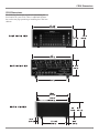
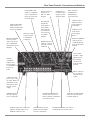
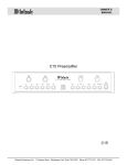
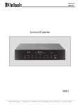
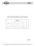
Owners Manual CR16 Audio/Video Multizone Control System CR16 McIntosh Laboratory, Inc. 2 Chambers Street Binghamton, New York 13903-2699 Phone: 607-723-3512 FAX: 607-724-0549 The lightning flash with arrowhead, within an equilateral triangle, is intended to alert the user to the presence of uninsulated dangerous voltage within the products enclosure that may be of sufficient magnitude to constitute a risk of electric shock to persons. WARNING - TO REDUCE RISK OF FIRE OR ELECTRICAL SHOCK, DO NOT EXPOSE THIS EQUIPMENT TO RAIN OR MOISTURE. IMPORTANT SAFETY INSTRUCTIONS! PLEASE READ THEM BEFORE OPERATING THIS EQUIPMENT. General: 1. Read these instructions. 2. Keep these instructions. 3. Heed all warnings. 4. Follow all instructions. 5. Warning: To reduce risk of fire or electrical shock, do not expose this equipment to rain or moisture. This unit is capable of producing high sound pressure levels. Continued exposure to high sound pressure levels can cause permanent hearing impairment or loss. User caution is advised and ear protection is recommended when playing at high volumes. 6. Caution: to prevent electrical shock do not use this (polarized) plug with an extension cord, receptacle or other outlet unless the blades can be fully inserted to prevent blade exposure. Attention: pour pevenir les chocs elecriques pas utiliser cette fiche polarisee avec un prolongateur, une prise de courant ou un autre sortie de courant, sauf si les lames peuvent etre inserees afond ans en laisser aucune partie a decouvert. 7. Unplug this apparatus during lightning storms or when unused for long periods of time. 8. Only use attachments/accessories specified by the manufacturer. 2 The exclamation point within an equilateral triangle is intended to alert the user to the presence of important operating and maintenance (servicing) instructions in the literature accompanying the appliance. NO USER-SERVICEABLE PARTS INSIDE. REFER SERVICING TO QUALIFIED PERSONNEL. To prevent the risk of electric shock, do not remove cover or back. No user serviceable parts inside. Installation: 9. The equipment shall be installed near the AC Socket Outlet and the disconnect device shall be easily accessible. 10. Do not block any ventilation openings. Install in accordance with the manufacturers instructions. 11.Do not install near any heat sources such as radiators, heat registers, stoves, or other equipment (including amplifiers) that produce heat. 12. Do not use this equipment near water. 13. Do not expose this equipment to dripping or splashing and ensure that no objects filled with liquids, such as vases, are placed on the equipment. 14. Use only with the cart, stand, tripod, bracket, or table specified by the manufacturer, or sold with the equipment. When a cart is used, use caution when moving the cart/equipment combination to avoid injury from tip-over. Connection: 15. Connect this equipment only to the type of AC power source as marked on the unit. 16. Protect the power cord from being walked on or pinched particularly at plugs, convenience receptacles, and the point where they exit from the equipment. 17. Do not defeat the safety purpose of the polarized or grounding-type plug. A polarized plug has two blades with one wider than the other. A grounding type plug has two blades and a third grounding prong. The wide blade or the third prong are provided for your safety. If the provided plug does not fit into your outlet, consult an electrician for replacement of the obsolete outlet. 18. Do not overload wall outlets, extension cords or integral convenience receptacles as this can result in a risk of fire or electric shock. 19. To completely disconnect this equipment from the AC Mains, disconnect the power supply cord plug from the AC receptacle. Care of Equipment: 20. Clean only with a dry cloth. 21. Do not permit objects or liquids of any kind to be pushed, spilled and/or fall into the equipment through enclosure openings. 22. Unplug the power cord from the AC power outlet when left unused for a long period of time. Repair of Equipment: 23.Refer all servicing to qualified service personnel. Servicing is required when the equipment has been damaged in any way, such as power-supply cord or plug is damaged, liquid has been spilled or objects have fallen into the equipment, the equipment has been exposed to rain or moisture, does not operate normally, or has been dropped. 24. Do not attempt to service beyond that described in the operating instructions. All other service should be referred to qualified service personnel. 25. When replacement parts are required, be sure the service technician has used replacement parts specified by McIntosh or have the same characteristics as the original part. Unauthorized substitutions may result in fire, electric shock, or other hazards. 26. Upon completion of any service or repairs to this product, ask the service technician to perform safety checks to determine that the product is in proper operating condition. Thank You Your decision to own this McIntosh CR16 Audio/Video Control System ranks you at the very top among discriminating music listeners. You now have The Best. The McIntosh dedication to Quality, is assurance that you will receive many years of musical enjoyment from this unit. Please take a short time to read the information in this manual. We want you to be as familiar as possible with all the features and functions of your new McIntosh. Please Take A Moment The serial number, purchase date and McIntosh dealer name are important to you for possible insurance claim or future service. The spaces below have been provided for you to record that information: Serial Number: Purchase Date: Dealer Name: Technical Assistance If at any time you have questions about your McIntosh product, contact your McIntosh dealer who is familiar with your McIntosh equipment and any other brands that may be part of your system. If you or your dealer wish additional help concerning a suspected problem, you can receive technical assistance for all McIntosh products at: McIntosh Laboratory, Inc. 2 Chambers Street Binghamton, New York 13903 Phone: 607-723-1545 Fax: 607-723-3636 Customer Service If it is determined that your McIntosh product is in need of repair, you can return it to your dealer. You can also return it to the McIntosh Laboratory Service Repair department. For assistance on factory repair return procedure, contact the McIntosh Repair Department at: McIntosh Laboratory, Inc. 2 Chambers Street Binghamton, New York 13903 Phone: 607-723-3515 Fax: 607-723-1917 Copyright 2000 ã by McIntosh Laboratory, Inc. 3 Table of Contents Safety Instructions ............................................................ 2 Thank You and Please Take a Moment............................. 3 Technical Assistance and Customer Service .................... 3 Table of Contents and General Notes ............................... 4 Connector Information ..................................................... 5 Introduction ...................................................................... 6 Performance Features ....................................................... 6 Dimensions ....................................................................... 7 Installation ........................................................................ 8 Rear Panel Controls, Connections and Switches ............... 9 How to Connect the CR16 with a MX132 ...................... 10 How to Connect the CR16 with a MX130/C39............... 12 How to Connect the CR16 in a Stand Alone System ...... 14 How to Connect Additional CR16s in a System ............ 16 Zone Location and Setting Listings ................................. 18 CR16 Front Panel Displays, Push-Buttons, and Switch ....................................................................... 20 How to Operate ................................................................ 21 How to Operate in Remote Zones ................................... 22 How to Program the CR16 .............................................. 22 Remote Control Push-Buttons ......................................... 24 How to Operate by Remote Control ................................ 25 Specifications .................................................................. 26 Packing Instructions ........................................................ 27 General Notes 1. Connecting Cables and Connectors are available from the McIntosh Parts Department: Data and Power Control Cable Part No. 170-202 Six foot, shielded 2 conductor, with 1/8 inch stereo mini phone plug on each end. MX130/C39 to CR16 Cable Part No. 170-203 Three foot, DB25, Shielded, straight through, 25 conductor male-to-male cable. MX132 to CR16 and CR16 to CR16 Cable Part No. 170-430 Six foot, DB37, shielded, straight through, 37 conductor male-to-male cable. Control Center to Multi Channel Power Amplifier Cable Part No. 170-631 Six foot, DB25, shielded, straight through, 25 conductor male-to-female cable. CR16 Keypad Terminal Plug Part No. 117-634 Five Pin connector for attaching the 4 conductor cable to the CR16 Keypad Socket. 2. The Main AC Power going to the CR16 and any other McIntosh Component(s) should not be applied until all the system components are connected together. When the CR16 and other McIntosh Components are in their Standby Power Off Mode the Microprocessors Circuitry inside each component is active and communication is occurring between them. Failure to do so could result in malfunctioning of some or all of the systems normal operations. 4 3. Up to four sensors or keypads can be wired in parallel for a single zone and up to six CR16s can be connected together in one system, along with a MX132/MX130/C39. 4. For additional information on Video/Audio connections, refer to the owners manual(s) for the component(s). 5. The CR16 Input Source Name DVD is equivalent to VAux on some McIntosh Keypads, Remote Controls and Audio/Video Control Centers. 6. If the CR16 is interconnected with a McIntosh MX132/ MX130/C39 A/V Control Center, and both components are located together, the internal front panel IR sensor on all the CR16(s) must be disabled. When multiple CR16s are connected together in a stand alone system, the front panel sensors on all the CR16s, except for the first CR16, also need to be disabled. This avoids interference problems caused by sending remote control IR commands simultaneously to the front panel sensors of all the units. To disable the CR16 Front Panel Sensor, move the recessed slide switch to the Off position. It is located through the opening in the bottom panel behind the Front Panel between the RESET and MUTE Pushbuttons. 7. When the CR16 is connected with a MX132/MX130/C39 A/V Control Center, certain Analog Audio Inputs and their Data Control Signals from the A/V Control Center are passed on to the CR16 via the DB37 or DB25 connectors. The MX132 has re-assignable input names; the number in parenthesis, to the left of the factory default names, refers to actual connections on the rear panel of the MX132. CR16 Inputs TUNER AUX CD TAPE TV LV VCR DVD MX132 Inputs TUN (0) AUX (1) CD2 (3) TAPE 1 (4) TV (7) LV (8) VCR1 (9) DVD (11) MX130/C39 Inputs TUNER AUX CD2 TAPE 1 None None None None 8. If an Audio Source Component, such as a separate tuner, is connected to the CR16 Tuner Input and the CR16 is connected to a McIntosh A/V Control Center (MX132/ MX130) conflict will occur between the two tuners. To prevent this from happening it is necessary to disable, in the DB37 or DB25 interconnecting cable between the two units, the Left & Right Audio along with the Data Control for that input. This can be simply performed by cutting out the three pins for that input. The pin outs for both the DB37 and DB25 connectors are shown below: General Notes and Connector Information Controller Input B (DB37 Connector): 1. Accessory-On 14. LV-Left 2. SYS-Off 15. TV-Left 3. Sum Data 16. Aux-Left 4. DVD-Data 17. Tape 1-Left 5. LV-Data 18. Tuner-Left 6. Aux-Data 19. CD-Left 7. Tuner-Data 20. Video Power 8. N/C 21. Ground 9. N/C 22. Home-Data 10. N/C 23. VCR-Data 11. Ground 24. TV-Data 12. DVD-Left 25. Tape-Data 13. VCR-Left Controller Input A (DB25 Connector): 1. Aux-Left 10. N/C 2. TV-Left 11. CD 2-Data 3. N/C 12. Tape 1-Data 4. Tape 1-Left 13. Video Power 5. Tuner-Left 14. Aux-Right 6. CD 2-Left 15. TV-Right 7. Ground 16. N/C 8. Ground 17. Tape 1-Right 9. Tuner-Data 18. Tuner-Right 26. CD-Data 27. N/C 28. N/C 29. Ground 30. DVD-Right 31. VCR-Right 32. LV-Right 33. TV-Right 34. Aux-Right 35. Tape-Right 36. Tuner-Right 37. CD-Right 19. CD-Right 20. SYS-Off 21. Accessory On 22. Aux-Data 23. Sum Data 24. N/C 25. Home Data 9. When connecting a dedicated source component to the ZONE AUX IN Jacks, it is important to also connect a data cable to the ZONE AUX IN DATA Jack. If a McIntosh Component without a Data Port or a non-McIntosh Component is connected to the ZONE AUX IN Jacks, it is important to insert a stereo mini phone plug with the tip to ring shorted together. This allows the CR16 to process the signal present at the ZONE AUX IN Jacks instead of the source connected to the regular AUDIO/VIDEO INPUT Jacks, for that Zone only. Connector Information Keypad Terminal Connector To use a WK-3 or WK-4 keypad, connect the shield and four leads of a shielded 4 conductor cable to a keypad terminal connector, according to the numbers listed below. There is a similar numbered connector built-in to each keypad. 1. Supply Voltage Positive 2. Supply Voltage Negative 3. Cable Shield 4. Signal Data 5. Signal Data Gnd. Balanced Outputs Din Connector Pin Layout Note: Refer to figure 1. 1. Left Channel (-) 2. (Not used) 3. Right Channel(-) 4. Left Channel Gnd. 5. Right Channel Gnd. 6. Left Channel (+) 7. Right Channel (+) Figure 1 Multi-Channel Din Connector Pin Layout Note: Refer to figure 1. 1. Zone 3-Pwr. Ctrl. 2. Zone 1-Pwr. Ctrl. 3. Pwr. Ctrl. (Main) 4. Zone 2-Pwr. Ctrl. 5. Video Power 6. Zone 4-Pwr. Ctrl. 7. Gnd. Pwr. Ctrl. Din Connector Pin Layout Note: Refer to figure 1. 1. Zone 3-Pwr. Ctrl. 2. Zone 1-Pwr. Ctrl. 3. Power On Output 4. Zone 2-Pwr. Ctrl. 5. Video Power 6. Zone 4-Pwr. Ctrl. 7. Gnd. RS 232 DB9 Connector Pin Layout 1. N/C 6. N/C 2. Data Out (TXD)In (RXD) 7. N/C 3. Data In (RXD) 8. N/C 4. N/C 9. N/C 5. Gnd. Multi-Channel Amp DB25 Connector Pin Layout 1. Zone 2-Left 14. Zone 2-Left Gnd. 2. Zone 1-Left 15. Zone 1-Left Gnd. 3. Zone 2-Right 16. Zone 2-Right Gnd. 4. Zone 3-Left 17. Zone 3-Left Gnd. 5. Zone 1-Right 18. Zone 1-Right Gnd. 6. Zone 3-Right 19.Zone 3-Right Gnd. 7. Zone 4-Left 20. Zone 4-Left Gnd. 8. Zone 4-Right 21. Zone 4-Right Gnd. 9. N/C 22. N/C 10. N/C 23. Zone 3-Pwr. Ctrl. 11. Zone 1-Pwr. Ctrl. 24. Zone 4-Pwr. Ctrl. 12. Zone 2-Pwr. Ctrl. 25. Pwr. Ctrl. Gnd. (Main) 13. Pwr. Ctrl. (Main) 5 Introduction and Performance Features Introduction Now you can take advantage of traditional McIntosh standards of excellence in the CR16 advanced design Audio/ Video Multizone Control System. You only need to push a button on a remote controller or a keypad to enjoy music and video programs throughout your home with McIntosh quality and reliability. The heart of the CR16 consists of four, independent, remotely controlled stereo preamplifiers. Performance Features · Four Independent Preamplifiers The CR16 consists of four independent stereo Audio/Video preamplifiers that can be remotely controlled from four separate zones. The front panel display shows the status of each zone. · Separate Programming Each of the four zones can be programmed from the CR16 front panel for selection of signal source and wake-up volume level. · Eight Source Selection Select any of four stereo audio/video signal sources, and four stereo audio signal sources in each zone using a Keypad or Remote Control. · Local Source Zone Selection An audio/video or audio only signal source component can be dedicated to operate only in a specific zone. · Independent Zone Tone Adjustment Individual bass and treble controls for each zone allow tone shaping to optimize audio performance for different speakers and room acoustics. · Video Switching Matched and buffered video switching ensures perfect picture integrity from the latest high resolution video sources. · Four Keypads and/or Sensors per Zone Each remote zone can accommodate up to four keypads or wall sensors to select and operate all the available signal source components. 6 · Front Panel LED Status Indicators Long life LED indicators show active zones, program source that has been selected and volume level in each zone. · RS 232 Port Allows for control of the CR16 with Remote Control Touch Panels and other external control systems. · Zone Volume Trim Adjustment The CR16 provides for each Zone, the adjustment of maximum Volume to compensate for differences in speaker efficiency and room acoustics. · Front Panel Source Selection The CR16 Front Panel allows for selection of the source and volume in all four zones at any time. · Buffered Video Outputs Each CR16 Video Input also has an corresponding Video Output. The Video Outputs are buffered by special Video Amplifiers to prevent signal degradation and allows the Video Signal Source to pass onto the next CR16 or the McIntosh Audio/Video Control Center. · Multiple Multizone Capable Multiple McIntosh CR16s Controllers can be connect together for additional zones. Six CR16s can provide a total of 24 independent zones. · Zone Control Lockout The CR16 has a unique control system that permits a selected zone to have access to a specific source and adjust the volume for the source, but prevents controlling the functioning for that source in that zone. CR16 Dimensions CR16 Dimensions The following dimensions can assist in determining the best location for your CR16. There is additional information on the next page pertaining to installing the CR16 into cabinets. 17-1/2" 44.45cm Front View of the CR16 7 -5/8" 7 -1/8" 18.10cm 19.37cm 17" 43.18cm Rear View of the CR16 6 -5/16" 16.03cm 13 -1/4" 33.66cm 15-3/4" 40.01cm 14-9/16" 36.99cm Side View of the CR16 3/16" 0.48cm 6-1/2" 16.51cm 13/16" 2.06cm 11-17/32" 29.29cm 29/32" 2.30cm 7 Installation Installation The CR16 can be placed upright on a table or shelf, standing on its four 1 inch high feet. The four feet may be removed from the bottom of the CR16 when it is custom installed as outlined below. The four feet together with the mounting screws should be retained for possible future use if the CR16 is removed from the custom installation and used free standing. It also can be custom installed in a piece of furniture or cabinet of your choice. The required panel cutout, ventilation cutout and unit dimensions are shown. CR16 Front Panel Always proCustom Cabinet Cutout vide adequate ventilation for your CR16. Cool operation ensures the longest possible operating life for any electronic instrument. Do not install the Cabinet CR16 directly Front Panel above a heat generating component such as a high powered amplifier. If all the components are CR16 Side View installed in a in Custom Cabinet single cabinet, a quiet running ventilation fan can be Support a definite asset in Shelf maintaining all the system components at the coolest possible operating tem2-13/16" perature. CR16 Bottom View 7.14cm A custom cabi- in Custom Cabinet net installation should provide the following minimum spacing dimensions for cool operation. Allow at least 2 inches (5.08 cm) above the top, 2 inches (5.08cm) below the bottom and 1 inch (2.54 cm) on each side of the Control Center, so that airflow is not obstructed. Allow 20 inches (50.8 cm) depth behind the front panel. Be sure to cut out a ventilation hole in the mounting shelf according to the dimensions in the drawing. 17-1/16" 43.34cm 6 -5/8" 16.83cm Cutout Opening for Custom Mounting Cutout Opening for Ventilation 1/2" Spacers 1.27cm 3-1/2" 8.89cm 9-5/32" 15-5/32" 24.77cm 38.50cm Cutout Opening for Ventilation 9-25/64" 23.85cm 8 Chassis Rear Panel Controls, Connections and Switches DATA PORTs send signals to compatible source components to allow for remote control functioning MULTI-CHANNEL AMP connects to a McIntosh multi-channel power amplifier MULTI-CHANNEL connector which sends a turn-on signal to a McIntosh multi-channel power amplifier PWR CTL sends a turn-on signal to a McIntosh Component Keypad connector allows use of WK-3 or WK-4 keypads UNBALanced OUTPUTS feed signals to power amplifier inputs VIDEO OUT TO MONitor sends a video signal to a monitor/TV BALANCED OUTPUTS send signals to power amplifier inputs and the switch that selects Fixed or Variable Outputs Dedicated Local Zone Audio/ Video Signal Source BASS and TREBLE controls provide ±12dB adjustment from the flat center position HOME Data Port connects to the optional HC-1 Home Controller Level control provides ± 6dB adjustment, for the maximun volume level, from the center position POWER CONTROL Outputs send turn-on signals to a McIntosh Power Controller RS232 connector for use with an external control system Connect the CR16 power cord to a live AC outlet. Refer to information on the back panel to determine the correct voltage VIDEO INPUTS for Video signal source components VIDEO OUTPUTS to send video signals to another CR16 or to a McIntosh Control Center EXT (external) SENSOR for a McIntosh Keypad or IR sensor CONTROLLER INPUT B connects from a previous CR16 Controller or McIntosh A/V Control Center AUDIO INPUTS accept signals from the outputs of source components TO NEXT CONTROLLER connects to the next CR16 Controller Input B CONTROLLER INPUT A connects to a McIntosh A/V Control Center 9 How to Connect the CR16 with a MX132 Monitor/TV 1. Connect a McIntosh Multi-Channel Amplifier with a DB25 computer type cable from the CR16 Multi-Channel Amp connector to amplifier input connector. Note: Both audio and zone power control pass through this cable. Discrete zone audio cables may also be used, either balanced or unbalanced. Refer to page 4 for the DIN plug balanced terminal connections. Also connect a cable from the CR16 DIN Multi-Channel Amp connector to the matching connector on the amplifier to provide zone power control. 2. Connect a WK-3/WK-4 keypad, using 4 conductor shielded cable to a zone terminal connector. Note: A WK-2 keypad or R649 Wall Sensor connected to the Zone Sensor Connector with RG6 or RG59U coax cable may also be used. 3. Connect the video outputs of A/V source components to the CR16 video inputs and the CR16 video outputs to the matching MX132 video inputs. 4. Connect the Audio Outputs from A/V source components to the matching MX132 Inputs. 5. For a dedicated Zone Source Component, connect the Audio/Video Outputs and the Data Port Input to the CR16 Zone Aux In connectors. 6. Connect the Video Out To Mon to the Video input of a remote zone TV or monitor. 7. Connect a DB37 cable from the CR16 Controller Input B Connector to the To Multizone Controller Connector on a McIntosh MX132. 8. Connect a Power Control cable from the CR16 POWER CTL (Control) jack to the Power Control In of a McIntosh Tuner. 9. Connect a Power Control cable from the McIntosh Tuner Power Control Out Jack to the Power Control In of a McIntosh DVD Player and then onto the next McIntosh Source Component. 10. Connect a Data cable from the CR16 DVD DATA PORT to the DATA IN of a McIntosh DVD Player. 11. Connect the CR16 power cord to a live AC outlet. McIntosh Eight Channel Amplifier 10 McIntosh Keypad How to Connect the CR16 with a MX132 McIntosh Tuner To AC Outlet McIntosh A/V Control Center McIntosh DVD Player 11 How to Connect the CR16 with a MX130/C39 Monitor/TV 1. Connect a McIntosh Multi-Channel Amplifier with a DB25 computer type cable from the CR16 Multi-Channel Amp connector to amplifier input connector. Note: Both audio and zone power control pass through this cable. Discrete zone audio cables may also be used, either balanced or unbalanced. Refer to page 4 for the DIN plug balanced terminal connections. Also connect a cable from the CR16 DIN Multi-Channel Amp connector to the matching connector on the amplifier to provide zone power control. 2. Connect a WK-3/WK-4 keypad, using 4 conductor shielded cable to a zone terminal connector. Note: A WK-2 keypad or R649 Wall Sensor connected to the Zone Sensor Connector with RG6 or RG59U coax cable may also be used. 3. Connect a DB25 cable from the CR16 Controller Input A Connector to the To Multiroom Controller Connector on a McIntosh MX130/C39. Note: The DB25 cable passes only the CD2, Tuner, Tape 1 and Aux audio along with matching Data, Sys Off and Power Control signals from the control center to the CR16. 4. Connect the video outputs of A/V source components to the CR16 video inputs and the CR16 video outputs to the matching MX130/C39 video inputs. 5. Connect the Audio Outputs from A/V source components to both the CR12 and C39/MX130 inputs using a Y adapter if necessary. 6. For a dedicated Zone Source Component, connect the Audio/Video Outputs and the Data Port Input to the CR16 Zone Aux In connectors. 7. Connect the Video Out to Mon to the Video input of a remote zone TV or monitor. 8. Connect a Power Control cable from the CR16 POWER CTL (Control) jack to the Power Control In of a McIntosh Tuner. 9. Connect a Power Control cable from the McIntosh Tuner Power Control Out Jack to the Power Control In of a McIntosh DVD Player and then McIntosh Eight Channel Amplifier onto the next McIntosh Source Component. 10. Connect a Data cable from the CR16 DVD DATA PORT and the MX130/C39 DATA PORT to the DATA IN of a McIntosh DVD Player inputs using a Y adapter if necessary. 11. Connect the CR16 power cord to a live AC outlet. 12 McIntosh Keypad How to Connect the CR16 with a MX130/C39 McIntosh Tuner To AC Outlet McIntosh A/V Control Center McIntosh DVD Player Y Adapters 13 How to Connect the CR16 in a Stand Alone System Monitor/TV 1. Connect a McIntosh Multi-Channel Amplifier with a DB25 computer type cable from the CR16 Multi-Channel Amp connector to amplifier input connector. Note: Both audio and zone power control pass through this cable. Discrete zone audio cables may also be used, either balanced or unbalanced. Refer to page 4 for the DIN plug balanced terminal connections. Also connect a cable from the CR16 DIN Multi-Channel Amp connector to the matching connector on the amplifier to provide zone power control. 2. Connect a WK-3/WK-4 keypad, using 4 conductor shielded cable to a zone terminal connector. Note: A WK-2 Keypad or R649 Wall Sensor connected to the Zone Sensor Connector with RG6 or RG59U coax cable may also be used. 3. Connect the Video Outputs of A/V Source Components to the CR16 Video Inputs. 5. For a dedicated Zone Source Component, connect the Audio/Video Outputs and the Data Port Input to the CR16 Zone Aux In connectors. 6. Connect the Video Out to Mon to the Video input of a remote zone TV or monitor. 7. Connect a Power Control cable from the CR16 POWER CTL (Control) jack to the Power Control In of a McIntosh Tuner. 8. Connect a Power Control cable from the McIntosh Tuner Power Control Out Jack to the Power Control In of a McIntosh DVD Player and then onto the next McIntosh Source Component. 9. Connect a Data cable from the CR16 DVD DATA PORT to the DATA IN of a McIntosh DVD Player. 10. Connect the CR16 power cord to a live AC outlet. McIntosh Eight Channel Amplifier 14 McIntosh Keypad How to Connect the CR16 in a Stand Alone System McIntosh Tuner To AC Outlet McIntosh DVD Player 15 How to Connect Additional CR16s in a System Monitor/TV 1. Connect a McIntosh Multi-Channel Amplifier with a DB25 computer type cable from the CR16 Multi-Channel Amp connector to amplifier input connector. Note: Both audio and zone power control pass through this cable. Discrete zone audio cables may also be used, either balanced or unbalanced. Refer to page 4 for the DIN plug balanced terminal connections. Also connect a cable from the CR16 DIN Multi-Channel Amp connector to the matching connector on the amplifier to provide zone power control. 2. Connect a WK-3/WK-4 keypad, using 4 conductor shielded cable to a zone terminal connector. Note: A WK-2 keypad or R649 Wall Sensor connected to the Zone Sensor Connector with RG6 or RG59U coax cable may also be used. 3. Connect the video outputs of A/V source components to the CR16 video inputs and the CR16 video outputs to the next CR16 video inputs. 5. For a dedicated Zone Source Component, connect the Audio/Video Outputs and the Data Port Input to the CR16 Zone Aux In connectors. 6. Connect the Video Out to Mon to the Video input of a remote zone TV or monitor. 7. Connect a DB37 cable from the CR16 Controller To Next Controller Output Connector to the Controller Input B Connector on the next CR16. 8. Connect a Power Control cable from the CR16 POWER CTL (Control) jack to the Power Control In of a McIntosh Tuner. 9. Connect a Power Control cable from the McIntosh Tuner Power Control Out Jack to the Power Control In of a McIntosh DVD Player and then onto the next McIntosh Source Component. 10. Connect a Data cable from the CR16 DVD DATA PORT to the DATA IN of a McIntosh DVD Player. 11. Connect the CR16 power cord to a live AC outlet. McIntosh Eight Channel Amplifier 16 McIntosh Keypad How to Connect Additional CR16s in a System McIntosh Tuner To AC Outlet Additional CR16 McIntosh DVD Player To next CR16 or A/V Control Center To next CR16 or A/V Control Center 17 Zone 1 Locations and Settings /RFDWLRQ Zone 2 Locations and Settings /RFDWLRQ 5RRP1DPH 'HGLFDWHG6RXUFH&RPSRQHQW 'HGLFDWHG6RXUFH&RPSRQHQW &RPSRQHQW &RPSRQHQW 1DPH 1DPH 3URJUDPPLQJ 3URJUDPPLQJ )XQFWLRQ1DPH 18 <HV 5RRP1DPH 1R )XQFWLRQ1DPH $FFHVVRU\ $FFHVVRU\ &RQWURO2II &RQWURO2II $FFHVVRU\2Q $FFHVVRU\2Q 7UDQVSRUW3OD\ 7UDQVSRUW3OD\ :DNHXSWR/DVW :DNHXSWR/DVW 6RXUFHDQG 6RXUFHDQG 9ROXPH 9ROXPH :DNHXSWR :DNHXSWR 6DPH6RXUFH 6DPH6RXUFH DQG9ROXPH DQG9ROXPH 'HIDXOW6RXUFH 'HIDXOW6RXUFH 'HIDXOW9ROXPH 'HIDXOW9ROXPH <HV 1R Zone Location and Setting Listings Zone 3 Locations and Settings /RFDWLRQ Zone 4 Locations and Settings 5RRP1DPH /RFDWLRQ 'HGLFDWHG6RXUFH&RPSRQHQW 'HGLFDWHG6RXUFH&RPSRQHQW &RPSRQHQW &RPSRQHQW 1DPH 1DPH 3URJUDPPLQJ )XQFWLRQ1DPH <HV 5RRP1DPH 3URJUDPPLQJ 1R )XQFWLRQ1DPH $FFHVVRU\ $FFHVVRU\ &RQWURO2II &RQWURO2II $FFHVVRU\2Q $FFHVVRU\2Q 7UDQVSRUW3OD\ 7UDQVSRUW3OD\ :DNHXSWR/DVW :DNHXSWR/DVW 6RXUFHDQG 6RXUFHDQG 9ROXPH 9ROXPH :DNHXSWR :DNHXSWR 6DPH6RXUFH 6DPH6RXUFH DQG9ROXPH DQG9ROXPH 'HIDXOW6RXUFH 'HIDXOW6RXUFH 'HIDXOW9ROXPH 'HIDXOW9ROXPH <HV 1R 19 CR16 Front Panel Displays, Push-Buttons and Switch The LEDs indicate which Zone has front panel control and when it is in the programming mode The LED indicates if the zone selected has the accessory control off command programmed Disables the control operations of accessory components in any Zone The LED Displays indicate what signal sources have been selected for each Zone Program an accessory turn-on command when that source is selected Select any one of the Audio or Audio/Video signal sources for use in any Zone Turns off the entire McIntosh Audio/ Video System Resets all CR16 microprocessors The LED indicates if the mute function is active for the Zone selected Mutes or unmutes audio in any Zone that is turned-on 20 Selects the Zone you wish to control or program The LEDs indicate which Zones are The LED indicates if turned-on the Zone selected has the accessory on command programmed Turns on or off a specific Zone to operate or to allow Turns all AC programming power on or off The digital display indicates the % (Percent) of the maximum volume for the zone selected. After 10 seconds the display reverts to the volume setting for Zone 1 IR Sensor receives commands from a remote control Adjust the volume level up or down in any Zone LED is on when the AC power cord is connected to a live AC outlet, and the front panel POWER switch is turned to ON The LED indicates if the Zone selected has the transport play command programmed Issues a transport play command when that source is selected How to Operate the CR16 How to Operate the CR16 Power On Press the POWER switch to ON. The Red LED, to the left of the VOLUME Down q Push-button, lights to indicate the CR16 is in Standby Mode. To turn ON the CR16 press one of the ZONE ON/OFF push-buttons. Refer to figure 1. Note: The POWER Switch is only intended to be switched OFF when the CR16 Audio/Video Multizone Control System is not used for extended periods of time, like while away on vacation. During normal operation, the POWER Switch should stay in the ON position. Press one of the ZONE ON/ OFF push-buttons for turning the CR16 ON and OFF. The CR16 may also be turned ON or OFF from a McIntosh Keypad or with the supplied Remote Control. Figure 1 Zone On/Off Turn on and operate any of the four Zones by pressing a ZONE ON/OFF Push-button. The LED to the right of the ZONE ON/OFF Push-button will illuminate to indicate that particular Zone is ON. The Zone will turn ON with the default (or programmed) signal source and volume level. Press the ZONE ON/OFF Push-button a second time to turn the Zone OFF. Refer to figure 1. Note: If no programming has been performed, all Zones will turn ON to the Tuner Source at a volume indication of 20. System Off Normally, remote zones are turned on and off individually in each respective zone by pressing the Power push-button on a keypad or remote control. If you desire to turn off all zones of an entire CR16 system simultaneously, including a control center and accessory source components, you can press the Sys Off Push-button on the front panel. You can also turn off the entire system in any remote zone by pressing the Sys Off push-button on a keypad. Refer to figure 2. Figure 2 Note: Individual remote zones should normally be turned off with the Power Push-button since there may be other zones in use. Select/Program The SELECT/PROGRAM Push-buttons allow for two dif- ferent functions for each Zone of the CR16. When a Zone is first turned ON, the LED to the left of the SELECT/ PROGRAM Push-button will flash On and Off for about 10 seconds indicating the SELECT Mode is active for that Zone. During this period of time, Source Selection, Volume changes and Volume Muting are possible. At any time when a given Zone is ON, Source Selection,Volume changes and Volume Muting can be made by first pressing the SELECT/PROGRAM Push-button followed by selecting a different source, muting and/or volume level for that Zone. Pressing the SELECT/PROGRAM Push-button a second time, during that 10 second period of time, the control of that Zone will switch Off. Refer to page 22 for information on programming the CR16. Note: Ten seconds after Zones 2, 3 or 4 are turned ON, all front panel operating functions return to Zone 1 after 10 seconds even if Zone 1 is not active. For information on programming refer to page 22. Dedicated zone source components If a specific CR16 zone has a source component dedicated exclusively to that zone, it can be operated in that zone with a keypad or remote control. When a dedicated zone source component is connected, it replaces the source component that is connected to the CR16 Aux inputs. If the CR16 is connected with a Control Center which has a source component connected to its Aux inputs, that component will not be available in the zone with the dedicated source component. Bass, Treble and Level Controls Adjust the bass and treble controls for the desired tone shaping in each zone. Adjust the zone level controls to increase or decrease a maximum of 6dB from the center detent position. Volume changes with the level controls add or subtract from the turn on levels. Figure 3 Refer to figure 3. Balanced and UnBalanced Outputs Place the slide switch to the correct position according to the output hook-up, balanced or unbalanced connections. Reset of Microprocessors In the event that the controls of the CR16 stop functioning, there is a user reset function built in. Press the Reset pushbutton and this will reset the CR16 microprocessors. Refer to figure 2. 21 How to Operate in Remote Zones Power Press the Power push-button and the Zone will turn-on with either the default or programmed signal source and volume level. Press the Power push-button a second time to turn the Zone OFF. Note: Operations in remote Zones can be performed by pressing a push-button on a keypad or remote control. Refer to figures 4 and 5. The Remote Control Pushbuttons that are highlighted in white are for use with other McIntosh Control Centers. Source Selection Select and operate any available signal source by pressing the appropriate Keypad or Remote Control Push-button. Note: In order to Program a Zone for any function, it first must be switched OFF. Setting the same source and volume level 1. Press the Program Push-button for the Zone you wish to program. The LED next to the selected Zone will turnon with a constant indication. Volume The Turn-On Volume Level can be changed by pressing an UP p or DOWN q Volume Push-button. Note: After pressing a Program push-button, you must make any changes with 10 seconds of each other. After the 10 seconds, the programming for that Zone will turn Off. Figure 5 Note: Individual Remote Zones should normally be turned Off with the Power Push-button since there may be other Zones in use that would automatically be turned Off by the Sys OFF Pushbutton in a Specific Zone. Dedicated Zone Source Components If a specific CR16 Zone has a Source Component dedicated exclusively to that Zone, it can be operated with a 22 Introduction to Programming The default setting for each Zone is to turn-on with the Tuner as the Source and a Volume Level of 20. You can change the default setting to any of CR16 Inputs at the desired volume level. It is also possible to have a Zone turnon with the Last Selected Source and Volume Level Setting. A Power-On and Play Command can also programed for a compatible source component so that it occurs when the Zone is first turned-on. It is also possible to prevent the Control of a Selected Source for a given Zone yet allow listening and/or viewing of that source. All programming is stored in permanent memory and is retained until changed, even in the event of a power failure. Refer to figure 6. Figure 4 System Off Normally remote Zones are turned On and Off individually in each respective Zone by pressing the Power Push-button on a Keypad or Remote Control. If you desire to turn off the entire McIntosh Audio/Video System you can press the SYS Off Push-button. Keypad or Remote Control. When a dedicated Zone Source Component is connected, it replaces the source component that is connected to the CR16 Aux Input. If the CR16 is connected with a Control Center which has a Source Component connected to its Aux Input, that component will not be available in the Zone with the Dedicated Source Component. 2. Select a Source for that Zone by pressing any of the eight Source Push-buttons and the selected source front panel LED will turn-on. This will become the active Source whenever that Zone is first turned-on. 3. Press an Up p or Down Volume q Push-button to select the desired volume level in that Zone. The Front Panel Display will indicate the selected level. 4. Press Program Push-button again or wait 10 seconds to exit the programming mode. Setting the last selected source and volume level 1. Press the Program Push-button for the Zone you wish to program. The LED next to the selected Zone will turnon with a constant indication. Note: After pressing a Program Push-button, you must make any changes within 10 seconds of each other. After the 10 seconds, the programming for that Zone programming will turn Off. How to Operate in Remote Zones and Program the CR16 2. Press the Source Push-button, whose LED is currently illuminated. The entire row of Front Panel Source LEDs for that Zone will turn-off. 3. Press Program Push-button again or wait 10 seconds to exit the programming mode. The next time that Zone is turned-on it will come on with the last selected source and volume level. Accessory Power On or Off 1. Press the Program Push-button for the Zone requiring the Accessory Control On Function. 2. Press Accessory Control On to program a turn on signal. The LED next to the Accessory On Push-button will Turn-On to indicate accessory on command has been selected. 3. Press Program Push-button again or wait 10 seconds to exit the programming mode. Note: If the Acessory Control is already on just repeat the above procedures to turn off the feature. The accessory source component must have a Data cable interconnected with the CR16 in order to receive the turn-on command and must also have a power switch that automatically cycles off when AC power is removed. Transport Play 1. Press the Program Push-button for the Zone requiring a Transport Play Command. 2. Press the Source Push-button that requires the Transport Play Command. 3. Press the Transport Play Push-button. The LED next to the Transport Play Push-button will Turn-On to indicate the Transport Play Command has been selected. Note: If Accessory Power On is used in combination with Transport Play Command there is a 2 second time delay between the two commands. 4. Press Program Push-button again or wait 10 seconds to exit the programming mode. Accessory Control Off 1. Press the Program Push-button for the Zone requiring Accessory Control Off. 2. Press the Accessory Control Off Push-button. The Red LED to the right of the Accessory Control Off Pushbutton will turn ON to indicate that the Control function is Turned OFF for that Zone. 3. Press Program Push-button again or wait 10 seconds to exit the Programming Mode. Programming with a Keypad or Remote Control 1. Press the Source Push-button for the desired new Source. 2. Press an Up p or Down qVolume Push-button to select the desired volume level in that Zone. 3. Press and hold the new Source Push-button for 3 seconds. The zone audio will mute, indicating that the change has occurred. Release the push-button to unmute. The next time that Zone is turned on, the new signal source and volume level will be in effect. Figure 6 23 Remote Control Push-Buttons Turns AC Power ON or OFF to some McIntosh Components when connected via the Data Port Press to Power the CR16 ON or OFF Selects Functions for McIntosh Home Controller Selects one of the eight High Level Audio/Video Sources Selects On Screen Functions for McIntosh DVD Players and some CD Players Selects CD Player or Tape Recorder Functions and also performs various functions on a variety of McIntosh Components Selects the Fast Forward Mode on Disc Players and Tuning Up the AM/ FM Dial Press the push-button to illuminate the keys Press to review Tuner Station Presets and selects certain functions on McIntosh CD Players Selects the Rewind Mode on Disc Players and Tuning Down the AM/FM Dial Use to select tuner presets, disc tracks or any numbered operation Selects AM Tuner Operating Functions and Disc Selection on some McIntosh CD Players Selects FM Tuner Operating Functions and Track Selection on some McIntosh CD Players Mutes the audio Adjusts the volume level up or down Note: The Remote Control push-buttons that are highlighted in white are for use with other McIntosh Control Centers. 24 How to Operate the Remote Control The supplied remote control is capable of directly controlling the functions of contemporary McIntosh Source Components connected to the CR16. Earlier McIntosh source components and other brand source components can be controlled by the CR16 with the addition of a McIntosh Remote Control Translator (RCT). Note: Your McIntosh Dealer can assist you with the installation and operation of the Remote Control Translator (RCT). Mute Press the MUTE push-button to mute audio at the active Zone. Input Source Selection Press any of the eight input push-buttons to select a Audio/ Video Source. CD/Tape Functions Use these push-buttons to operate a CD player, CD changer or tape recorder. Acc Off Press ACC OFF to turn the power OFF to a McIntosh Disc Player. E Press E to perform various functions on a variety of McIntosh Components. It will also pause the playing of a disc or tape player. Lighting Press and release the LIGHTING push-button to momentarily illuminate the upper half of the remote control pushbuttons. Note: While the LIGHTING push-button is being depressed, the remote control will be unable to send a remote command. When the LIGHTING push-button is released, the push-buttons will continue to stay illuminated for approximately three seconds thus allowing you to send the desired command. Numbered Push-buttons Press push-buttons 0 through 9 to access tuner station presets or CD tracks/discs. Disc and Track Use the DISC and TRACK push-buttons when a CD player or changer is being used. Tuner Push-buttons Press the AM or FM push-button to select the desired broadcast band. Press and release the Channel Upp or Downqpush-button to move from station to station. Press and hold a Channel Upp or Downq push-button to move continuously from station to station. Press REVIEW Pushbutton to start the automatic brief audition of each of the presets stored in the tuner memory. Press REVIEW a second time to stop on a station preset and exit the review process. Volume Press the Up or Down VOLUME push-button to raise or lower the listening volume level. Acc On Press ACC ON to turn the power ON to a McIntosh Disc Player. 25 Specifications Specifications Frequency Response +0, -0.5dB from 20Hz to 20,000Hz Maximum Voltage Output 6Volts Total Harmonic Distortion 0.01% From 20Hz to 20,000Hz Sensitivity 250mV for 1.5V rated output Signal To Noise Ratio 90dB below rated output, (A Weighted) Maximum Input Signal 8Volts Input Impedance 22K ohms Output Impedance 600 ohms, Balanced and Unbalanced Tone Controls +12dB, -12dB from center detent position Voltage Gain Input to Variable Outputs, 14dB Input to Fixed (Balanced) Outputs, 0dB Power Requirements 100 Volts, 50/60Hz at 25 watts 110 Volts, 50/60Hz at 25 watts 120 Volts, 50/60Hz at 25 watts 220 Volts, 50/60Hz at 25 watts 230 Volts, 50/60Hz at 25 watts 240 Volts, 50/60Hz at 25 watts Note: Refer to the rear panel of the CR16 for the correct voltage Overall Dimensions 17-1/2 inches (44.5cm) W, 7-1/16 inches (17.9cm) H, 20 inches (50.8cm) D, (including clearance for connectors) Weight 27.2 pounds (12.2 Kg) net, 39.5 pounds (18 Kg) in shipping carton 26 Packing Instructions Packing Instructions In the event it is necessary to repack the equipment for shipment, the equipment must be packed exactly as shown below. It is very important that the four plastic feet are attached to the bottom of the equipment. This will ensure the proper equipment location on the bottom pad. Failure to do this will result in shipping damage. Use the original shipping carton and interior parts only if they are all in good serviceable condition. If a shipping carton or any of the interior part(s) are needed, please call or write Customer Service Department of McIntosh Laboratory. Please see the Part List for the correct part numbers. Quantity 1 2 Part Number 033762 033763 Description Shipping carton only End Cap 1 1 1 033620 033726 033729 Inside carton only Top Pad Bottom pad 4 4 4 018578 100159 104080 Plastic foot #10-32 x 3/4 screw #10 Flat washer 1 047920 Shipping carton complete with all the above parts Top Pad Unit with (4) feet on Bottom Cover Foot (4) 10-32 x -3/4 screws with washers Bottom Pad IMPORTANT (Read Above) End Cap Inside Carton Inside Carton Shipping Carton 27 McIntosh Laboratory, Inc. 2 Chambers Street Binghamton, NY 13903 McIntosh Part No. 040728