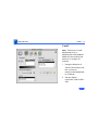
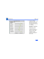
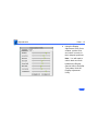
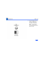
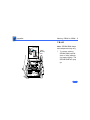
1
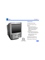
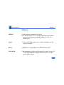
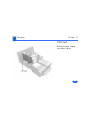
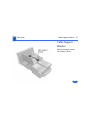
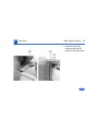
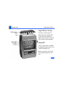
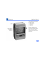
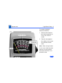
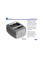
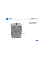
K Service Source
Power Macintosh G3
All-In-One
K Service Source
Basics
Power Macintosh G3
All-In-One
Basics
Overview - 1
Overview
Introducing the Power
Macintosh G3 All-In-One
design.
• The new all-in-one is
designed for education and
fulfills all the computing
needs of teachers and
students.
• Powerful and easy-to-use
video editing and multimedia
authoring features at an
affordable price.
Click the icon at left for a
QuickTime VR movie of the
Power Mac G3 All-In-One.
Basics
Overview - 2
Features of the Power Macintosh G3 All-In-One include
• PowerPC G3 microprocessor running at 233 MHz or
266 MHz
• RAM expandable to 384 MB in 3 DIMM slots using 64bit wide, 168-pin JEDEC-standard 3.3 V unbuffered
SDRAM DIMMs
• 512K of static RAM used as L2 cache on processor module
• Built-in 2D and 3D hardware graphics acceleration
• PERCH slot to support I/O card
• One modem slot on the I/O card for optional fax/modem
card
• 4 GB or 6 GB ATA hard drive
• 100 MB SCSI Iomega Zip drive
• CD-ROM ATAPI drive at 24X speed
• 1.4 MB SuperDrive
• One SCSI port
• Two GeoPort serial ports
• 10BASE-T Ethernet port
Basics
Overview - 3
• One ADB port
• Three PCI expansion slots to accept
• three 7-inch PCI cards, or
• three 15 W cards, or
• two 25 W cards, or
• one 15 W card and one 25 W card
• Fan speed thermally controlled
• Energy Saver control panel
• 2 MB video RAM expandable to 6 MB with
3.3 V, 100 MHz or faster SGRAM on a 144-pin small
outline dual inline memory module (SO-DIMM)
Basics
Overview - 4
Optional Build-to-Order Power Mac All-In-One Features:
• 100 MB SCSI Iomega Zip drive in the expansion bay
• 6 GB hard drive
• 64 MB (using one 64 MB DIMM) or 96 MB (using 1x
32 MB and 1x64 MB DIMM) of memory
• I/O, Audio/Video card
• 10/100 BaseT ethernet card
Basics
The Cuda Chip - 5
The Cuda Chip
The Cuda is a microcontroller chip. Its function is to
• Turn system power on and off
• Manage system resets from various commands
• Maintain parameter RAM (PRAM)
• Manage the Apple Desktop Bus (ADB)
• Manage the real-time clock
Many system problems can be resolved by resetting the Cuda
chip (see Symptom Charts for examples). Press the Cuda
reset button on the logic board to reset the Cuda chip. (See
“Logic Board Diagram” later in this chapter to locate the
Cuda reset button.) If you continue to experience system
problems, refer to “Resetting the Logic Board” in this
Basics chapter.
Basics
Resetting the Logic Board - 6
Resetting the Logic Board
Resetting the logic board can resolve many system problems
(refer to “Symptom Charts” for examples). Whenever you
have a unit that fails to power up, you should follow this
procedure before replacing any modules.
1
Unplug the computer.
3
Disconnect the power supply cable from the logic board
and then press the Cuda Reset button. (See “Logic
Board Diagram” later in this chapter to locate the Cuda
Reset button.)
2
4
5
Remove the battery from the logic board.
Wait at least 10 minutes before replacing the battery.
Make sure the battery is installed in the correct +/direction.
Basics
Resetting the Logic Board - 7
6
Reassemble the computer and test the unit.
Note: This procedure resets the computer’s PRAM. Be sure
to check the computer’s time/date and other system
parameter settings afterwards.
Basics
Sound - 8
Sound
The sound system for the Power Macintosh G3 computers is
implemented entirely on the I/O card. Each supports 16-bit
stereo sound output and input, available simultaneously.
The sound circuitry on the I/O card and system software can
create sounds digitally and either play the sounds through
speakers inside the enclosure or send the sound signals out
through the sound output jacks. The sound circuitry digitizes
and records sound as 16-bit samples. The computer can use
22.050K or 44.100K samples per second. The sound system
plays samples at the sampling rate specified in the Monitors
& Sound control panel.
Basics
Sound - 9
The Power Macintosh G3 also records sound from several
sources:
• A microphone connected to the line-level sound input
jack
• A compact disc in the CD-ROM player
• Analog sound from the cross-platform card in a PCI slot
• Analog sound from optional communication cards
• Internal Microphone
With each sound input source, sound playthrough can be
enabled or disabled.
Basics
Sound - 10
Sound Output
All sound output features for the Power Macintosh G3
computer are provided by the I/O card. The I/O card
provides one mini jack for sound output on the back of the
enclosure.
The output jacks are connected to the sound amplifier. The
mini jack is intended for connecting a pair of headphones or
amplified external speakers. There are two speakers and two
headphone jacks on the front of the system. Inserting a plug
into the sound output mini jack disconnects the internal
speaker.
Basics
Sound - 11
Sound Input
The I/O card provides a stereo sound input jack on the back
of the enclosure for connecting an external Apple PlainTalk
line-level microphone or other sound source pair of linelevel signals. The sound input jack accepts a standard 1/8inch stereophonic phone plug (two signals plus ground).
Note: The microphone for the Macintosh LC and LC II does
not work with the I/O cards.
Options in the Monitors & Sound control panel determine the
interaction between the sound input and output devices. The
sound circuitry normally operates in one of three modes:
• Sound playback—computer-generated sound is sent to the
speaker and the sound output jacks.
• Sound playback with playthrough—computer sound and
sound input are mixed and sent to the speakers and sound
output jacks.
Basics
Sound - 12
• Sound record with playthrough—input sound is recorded
and also sent to the speakers and sound output jacks.
Basics
PowerPC G3 and Backside Cache - 13
PowerPC G3 and Backside Cache
Backside cache is a significant architectural design change
from earlier PowerPC processors. The main advantage of the
backside cache architecture is the speed of the dedicated
CPU-to-L2 cache interface. Using the dedicated bus allows
the CPU to access the fast L2 cache storage through a high
speed bus without addressing the slower system bus or
competing with other devices attached to the system bus. In
comparison, a “far-side” cache running on the system bus
would limit that SRAM interface to 50MHz.
The PowerPC G3 microprocessor interfaces with SRAM
storage via a dedicated bus running at various multiples of
the core PLL CPU speed. With high speed L2 SRAM and a
dedicated L2 bus, the CPU can access stored information up
to the speed of the processor clock. L2 access is determined
by the clock ratio setting. For example, with a 250MHz
Basics
SDRAM DIMMs - 14
PowerPC G3, and a 2.5 L2 bus ratio, the backside cache bus
speed will be 100MHz, twice the speed of the system bus.
SDRAM DIMMs
Three DRAM expansion slots on the logic board accept 3.3 V
SDRAM unbuffered 8-byte DIMMs. The 168-pin DIMM has a
64-bit-wide data bus per bank. The minimum bank size
supported on the Power Macintosh G3 all-in-one model is 4
MB, and the largest is 64 MB. The largest DIMM supported
is a two-bank DIMM of 64 MB using 32 Mbit SDRAM
devices.
The Power Macintosh G3 All-In-One logic board supports a
maximum DRAM expansion of 384 MB. Fill all three slots
with 128 MB DIMMs.
Basics
SDRAM DIMMs - 15
The DRAM DIMMs can be installed one or more at a time. The
logic board supports only linear memory organization.
Therefore, no performance gains are seen when two DIMMs
of the same size are installed. Any supported size DIMM can
be installed in any DIMM slot, and the combined memory of
all the DIMMs installed will be configured as a contiguous
array of memory.
Important: Power Macintosh G3 computers use SDRAM
DIMMs. DIMMs from older Macintosh computers are not
compatible and should not be used even though they fit into
the DRAM DIMM slots.
Basics
SGRAM Video Memory - 16
SGRAM Video Memory
The Power Macintosh G3 logic board comes with 2 MB of
Synchronous Graphic RAM (SGRAM) video memory soldered
on. The logic board also contains a video memory expansion
slot that accepts a Small Outline DIMM (SO-DIMM) to
increase video memory up to a maximum of 6 MB. Apple
supports a 4 MB SGRAM SO-DIMM that is 32-bit wide,
144-pin, fast-paged, 100 MHz/10 ns cycle time or faster.
Important: Use only SGRAM SO-DIMMs. Never use the 256K
or 512K video memory DIMMs used in older Macintosh
computers.
Basics
DIMM Slots - 17
DIMM Slots
DRAM
DIMM
Slots
ROM Slot
(Do not remove
the ROM DIMM.)
Video Memory Expansion Slot
SGRAM SO-DIMM
Basics
- 18
Peripheral Component Interconnect
(PCI)
The Peripheral component Interconnect (PCI) expansion
slots accept 7-inch PCI cards. Install only expansion cards
that come with Macintosh drivers and are compliant with the
PCI 2.1 standard. Nubus™ cards cannot be used in these
expansion slots.
PCI offers significantly higher performance than the NuBus
architecture used in previous Macintosh models. Running at
33 MHz, the PCI bus is up to three times faster than NuBus,
offering overall enhanced system performance, particularly
in the areas of video and networking.
Basics
Internal Locator - 19
Internal Locator
Video Board
Power Supply
Analog Board
Zip Drive
Logic Board
CD-ROM Drive
Hard Drive
Floppy Drive
Basics
Rear View - 20
Rear View
Sound Output Port
Sound Input Port
SCSI Apple Ethernet Printer Monitor Internal
Port Modem
Port Desktop (10Base-T) &
Port External
Card
Bus
modem
Port
(ADB)
Port
Port
Access
Covers for
Expansion
Slots (3)
See next page for
optional AV card.
Basics
Optional AV Card - 21
Optional AV Card
Audio output ports
(right & left)
Composite Video Ports
(OUT and IN)
Sound Output Port
Audio Input Ports
(right & left)
S-Video Ports
(OUT and IN)
Sound Input Port
Optional AV ports
Basics
Logic Board - 22
Logic Board
Power Supply PERCH
Jumper Block
Slot
Ethernet
ADB
Port
Port
Monitor
Serial
SCSI
Port
Ports
Port
Internal SCSI
Connector
Cuda Reset Button
IDE Connector
PCI
Slots
Power Supply
Connector
Video Memory
SO DIMM
Floppy Drive
Connector
Voltage Regulator
Processor Jumper Block
Battery
LED
Speaker Power CD ROM
On/Off Audio DIMM
DRAM
DIMM
Microprocessor
Basics
Repair Strategy - 23
Repair Strategy
Service the Power Macintosh G3 computers through module
exchange and parts replacement. Customers can request onsite service from an Apple Authorized Service Provider Plus
(AASP+), Apple Assurance (US only), or Apple Canada
Technical Answerline (Cananda only). They can also choose
carry-in service from an AASP.
Ordering
Apple Service Providers planning to support the computer
systems covered in this manual may purchase Service
modules and parts to develop servicing capability. To order
parts, use the AppleOrder (US only) or ARIS (Canada only)
system and refer to the Power Macintosh G3 “Service Price
Pages.”
Basics
Repair Strategy - 24
Large businesses, universities, and K-12 accounts must
provide a purchase order on all transactions, including
orders placed through the AppleOrder (US only) or ARIS
(Canada only) system.
USA Ordering
US Service providers not enrolled in AppleOrder may fax
their orders to Service Provider Support (512-9088125) or mail them to
Apple Computer, Inc.
Service Provider Support
MS 212-SPS
Austin, TX 78714-9125
For US inquiries, please call Service Provider Support at
800-919-2775 and select option #1.
Basics
Repair Strategy - 25
Canadian Ordering
Canadian Service providers not enrolled in ARIS may fax
their orders to Service Provider Support in Canada (1800-903-5284). For Canadian inquiries, please call
Service Provider Support at 905-513-5782 and select
option #3.
Basics
Warranty/AppleCare/ARIS - 26
Warranty/AppleCare/ARIS
US Only
The Power Macintosh G3 computers are covered under the
Apple One-Year Limited Warranty. The AppleCare Service
Plan is also available for these products. Service Providers
are reimbursed for warranty and AppleCare repairs made to
these computers. For pricing information, refer to “Service
Price Pages.”
Canada Only
The Power Macintosh G3 computers are covered under
AppleCare. The Extended AppleCare Service Plan is also
available for these products. Service Providers are
reimbursed for warranty and AppleCare repairs made to
these computers. For pricing information, refer to “Service
Price Pages.”
K Service Source
Specifications
Power Macintosh G3 All-in-One
Specifications
Introduction - 1
Introduction
Specifications information for this product can be found in this chapter and also in the Spec
Database, which you can access in one of three ways:
— Launch it directly by double-clicking the Apple Spec Database runtime alias at the
top level of the Main Service Source CD.
— Select "Apple Spec Database" from the Service Source drop-down main menu.
— Click the Acrobat toolbar icon for the database, which is near the right end of the
toolbar with the letters "SP."
Specifications
Processor - 2
Processor
CPU
Processor Bus
PowerPC G3 RISC microprocessor running at 233 or 266 MHz
Built-in FPU
Requires system software version 8.1 or later with appropriate
Enabler version
64-bit wide, 66 MHz, supporting split address and data tenures
Specifications
Memory - 3
Memory
SDRAM
Cache
ROM
Video RAM
32 MB standard, expandable to 384 MB
Uses 168-pin, 64-bit, 10 ns, 100 MHz unbuffered synchronous
dynamic access memory (SDRAM) DIMMs (1K, 2K, or 4K
refresh rate)
512K of static RAM used as Level 2 cache integrated into the
processor module
4 MB ROM on 160-pin DIMM, 64-bit ROM data bus width
2 MB expandable to 4 MB or 6 MB using 32-bit wide, 144-pin, 3.3
V, fast-paged SGRAM SO-DIMM connector with 10 ns RAM
access time or faster
Specifications
I/O Interfaces - 4
I/O Interfaces
SCSI Port
External SCSI connector is 25-pin D-type connector. Supports up
to seven SCSI devices.
Serial Port
Two serial ports support AppleTalk and GeoPort serial protocols.
Accept 8-pin or 9-pin plugs.
ADB Port
One Apple Desktop Bus port for a keyboard, mouse, etc.
Ethernet Port
10Base-T, RJ-45
Specifications
Expansion
I/O Interfaces - 5
Three internal expansion slots, supporting 7-inch PCI expansion
cards, compatible with all PCI 2.1 specification-compliant cards
with the addition of Mac OS-specific software driver (not NuBus
compatible)
Accepts three PCI cards, or two 25-watt cards, or one 15-watt
card and one 25-watt card.
One internal expansion bay that accepts a 3.5” or 5.25” storage
device that is up to 1.625” (41.3 mm) high. Some models
come with a Zip drive already installed in one of the bays.
Specifications
I/O Devices - 6
I/O Devices
Keyboard
AppleDesign Keyboard
Mouse
ADB Mouse II
Microphone
Apple internal microphone standard
Specifications
Disk Storage - 7
Disk Storage
Hard Drive
2 GB or 4 GB internal ATA hard drive
6 GB internal on build-to-order systems
Floppy Drive
One Apple SuperDrive 1.4 MB floppy drive
CD-ROM Drive
One internal 24x ATAPI CD-ROM drive
Zip Drive
Optional 100 MB SCSI Iomega Zip drive
Specifications
Video - 8
Video
Built-in Video
Display
Video Display Modes
Graphics
acceleration
Multi-scan, tilt-and-swivel color display: 15-inch (13.8 inch
diagonal viewable image size), .28-mm dot pitch
Built-in monitor port supports:
• 640 x 480, 800 x 600, 832 x 624 at 32 bits per pixel
• 1024 x 768 at16 bits per pixel
Built-in graphics controller, 2D and 3D hardware graphics
acceleration of QuickDraw graphics
Specifications
I/O Cards - 9
I/O Cards
PERCH Slot
Sound
Modem Slot
The PERCH slot connector is a 182-pin microchannel connector
that supports the Apple I/O cards.
Note: The PERCH slot does not accept PCI cards.
Rear jack for stereophonic speakers
Supports 16 bits/channel stereo input and output
External 1/8" jack for sound in
Sample rates of 22.05, or 44.1 kHz
112-pin connector to accept optional fax/modem card
Note: Does not carry PCI signals
Specifications
Electrical - 10
Electrical
Line Voltage
90–264 V AC, rms, single phase
Frequency
50–60 Hz
Maximum Power
300 W maximum continuous
Specifications
Physical - 11
Physical
Dimensions
Height:
Width:
Depth:
Weight:
19.92 in. (498 mm)
16.08 in. (402 mm)
18.00 in. (450 mm)
59.5 lb. (27 kg); weight varies depending on devices installed
Specifications
Environmental - 12
Environmental
Operating
Temperature
50 to 104° F (10 to 40° C)
Storage
Temperature
-40 to 116° F (-40 to 47° C)
Relative Humidity
5–95% noncondensing
Maximum Altitude
10,000 ft. (3,048 m)
K Service Source
Take Apart
Power Macintosh G3
All-In-One
Take Apart
Chassis Carrier - 1
Chassis Carrier
No preliminary steps are
required before you begin
this procedure.
1
2
Loosen the four screws.
Pull the chassis carrier
half way out of the unit.
Take Apart
Chassis Carrier - 2
3
Disconnect the front
control panel cable, RGB
cable, main power cable,
and HDA power cable.
Take Apart
Chassis Carrier - 3
4
5
Press up on the tabs to
release the chassis
carrier.
Pull chassis carrier out
of unit.
Note: See graphic on next
page showing complete
chassis carrier out of the
unit.
Take Apart
Chassis Carrier - 4
Note: Graphic illustrates
modules and support
bracket located in
chassis carrier.
Take Apart
Hard Drive - 5
Hard Drive
Before you begin, remove
the chassis carrier.
Take Apart
Hard Drive - 6
1
Disconnect the hard
drive data cable and the
power cable from the
back of the hard drive.
Take Apart
Hard Drive - 7
2
Pull up the release latch
and slide the hard drive
forward to remove it
from the internal
chassis.
Note: Be sure to remove
the hard drive from its
carrier before
returning the drive to
Apple.
Take Apart
Floppy Drive - 8
Floppy Drive
Before you begin, remove
the chassis carrier.
Take Apart
Floppy Drive - 9
1
2
3
Pull up the release
latch, and slide the
floppy drive forward
enough to reach the
floppy cable.
Disconnect the cable
from the back of the
floppy drive.
Remove the floppy drive
from the unit.
Note: Be sure to remove
the EMI shield and floppy
drive carrier before
returning the drive to
Apple.
Take Apart
Zip Drive - 10
Zip Drive
Before you begin, remove
the chassis carrier.
Take Apart
Zip Drive - 11
1
2
3
Pull up the release
latch, and slide the Zip
drive forward enough to
reach the cables.
Disconnect the SCSI and
Zip power cables from
the back of the Zip drive.
Remove the Zip drive
from the unit.
Note: Be sure to remove
the EMI shield and Zip
drive carrier before
returning the drive to
Apple.
Take Apart
Adding a Zip Drive - 12
Adding a Zip Drive
There may be requests to add a zip drive
to a Power Mac G3 All-in-one
computer. Some prebuilt and build-toorder configurations do not include a
zip drive. Therefore, customers may
want to upgrade their systems by
installing a zip drive taken from
another computer, or by purchasing the
individual service parts.
See the Additional Procedures section
for instructions.
Take Apart
CD-ROM - 13
CD-ROM
Before you begin, remove
the chassis carrier.
08
Take Apart
CD-ROM - 14
1
2
Position the chassis
carrier on its side.
Disconnect the CD-ROM
power cable, CD-ROM
SCSI cable, and CD-ROM
audio cable from the
back of the CD-ROM
drive.
Take Apart
CD-ROM - 15
3
Pull down on the plastic
frame while squeezing
the latch. Slide the CDROM drive forward to
remove it from the unit.
Note: Be sure to remove
the EMI shield and CDROM carrier before
returning the drive to
Apple.
Take Apart
CD-ROM - 16
Replacement Note: If you
removed the CD-ROM cables
from the chassis you will
need to reposition them
before connecting the CDROM drive.
1
2
3
Tuck the CD-ROM power
cable, the CD-ROM SCSI
cable, and the CD-ROM
audio cable through the
hole in the plastic
chassis.
Reconnect the cables to
the CD-ROM drive.
Push CD-ROM into the
chassis until it clicks
into position.
Take Apart
I/O Card - 17
I/O Card
Before you begin, remove
the chassis carrier.
Take Apart
I/O Card - 18
1
2
Disconnect cables on the
I/O Card.
Remove two screws that
secure card to chassis.
Note: Be careful of the
voltage regulator when
removing or replacing
the I/O card.
Take Apart
I/O Card - 19
3
Remove external I/O
screw on chassis.
Take Apart
I/O Card - 20
4
5
Gently rock the I/O card
out of the socket.
Remove card from logic
board.
Replacement Note: Line up
back end (end nearest
voltage regulator) of I/O
card and push card down into
slot. Be careful not to
damage the voltage
regulator or modem.
Take Apart
Cable Support Bracket - 21
Cable Support
Bracket
Before you begin remove
the chassis carrier.
Take Apart
Cable Support Bracket - 22
1
Disconnect the SCSI
cable and the two IDE
cables on the logic board.
Take Apart
Cable Support Bracket - 23
2
3
4
Remove screw on cable
support bracket.
Open white plastic cable
retainer and remove
gray cables from the
support bracket.
Lift the metal support
bracket out of unit.
Take Apart
Logic Board - 24
Logic Board
Before you begin do the
following:
• Remove the chassis
carrier
• Remove I/O card
• Disconnect the SCSI and
IDE cables
• Remove cable clamp
support bracket
Caution: Review the ESD
precautions in Bulletins/
Safety.
Take Apart
Logic Board - 25
1
2
3
Disconnect the floppy
drive cable.
Pull the Zip drive out a
bit to disconnect the Zip
drive power cable.
Disconnect the CD-Audio
cable (located next to
battery).
Take Apart
Logic Board - 26
4
Remove the two silver
screws.
Note: Do not remove
ground wire from the
heatsink.
Take Apart
Logic Board - 27
5
Gently lift the logic
board out of the chassis
carrier.
Replacement Note: This
logic board requires that
jumper J28 be set properly
for the unit to function. The
power supply jumper, which
installs at J28, should cover
the pins marked "Mac" when
a new board is installed.
Take Apart
12
CRT EMI Shield - 28
CRT EMI Shield
±Warning: This product
contains high voltage and a
high-vacuum picture tube.
To prevent serious injury,
review CRT safety in
Bulletins/Safety.
Before you begin, do the
following:
• Remove the chassis
carrier
• Remove the top, side, and
rear panel housing
Take Apart
CRT EMI Shield - 29
1
Remove the six screws
on the EMI Shield.
Note: The EMI shield has
sharp edges. Be careful
not to cut yourself.
Take Apart
CRT EMI Shield - 30
2
3
Lift the shield up,
releasing the shield from
the metal tabs on the
chassis.
Remove the shield from
the unit.
Replacement Note: Make
sure the microphone cable is
pulled through the CRT
chassis frame so the EMI
shield doesn’t pinch the
microphone cable.
Take Apart
Power Supply - 31
Power Supply
Before you begin do the
following:
• Remove the chassis
carrier
• Remove the top, side, and
rear panel housing
• Remove the CRT EMI
shield
• Discharge the CRT
Take Apart
Power Supply - 32
1
2
Push tab in.
Lift and pull the power
supply up to clear the
pegs from the chassis
holes.
Note: The cables are still
attached to the power
supply at this point.
Take Apart
Power Supply - 33
3
Disconnect the multicolored power cable
(P904),the ground wire
(P911), and the 2-pin
brown wire (TH901),
from the power supply.
Take Apart
Power Supply - 34
4
5
Tilting the power
supply off to the side,
disconnect the remaining
cables on the power
supply board:
• P912
• P905
• P906
• P913
• P908
Note: P906 and P908
have locking connectors.
Pinch or squeeze to
release the connectors.
Remove power supply
from the chassis.
Take Apart
Power Supply - 35
Replacement Note: Some
connectors are impossible to
reconnect when the board is
in place. Before inserting
the power supply, connect
cables TH901, P908,
P913, P906, and P905.
Also, make sure the pegs on
the power supply reseat into
the holes in the chassis.
Take Apart
Power Supply - 36
Additional cable descriptions:
P912: Thermistor cable: a 2-wire gray & brown cable that
connects to the brown connector on the power supply board
P905: Fan cable: a 2-wire red &black cable
P906: a flat gray ribbon cable (922-3492). This cable is a
wide gray ribbon cable that connects to the I/O card and then
splits off into three cables, one goes to the front panel board,
one to the power supply board (P906), and one to the analog
board (P503).
P913: a 10-wire gray & blue cable (2 wires from this cable
split off and connect to P4 on the front panel board and the
other end connects to P505 on the analog board)
P908: a 5-wire gray & blue cable (P908 connects to P507
on the analog board)
Take Apart
Analog/Video Board - 37
Analog/Video
Board
Before you begin do the
following:
• Remove the chassis
carrier
• Remove the top, side, and
rear housing
• Remove the CRT EMI
shield
• Discharge the CRT
• Disconnect anode cap
Take Apart
Analog/Video Board - 38
1
Disconnect the
microphone (P703),
ground wire (P702),
degaussing wire
(P508), and the yoke
wire (P701).
Take Apart
Analog/Video Board - 39
2
3
Gently remove the CRT
video board.
Push in tab and lift
analog board out of
chassis holes.
Take Apart
Analog/Video Board - 40
4
5
Disconnect P502,
P503, P507, P506, and
P505.
Important: P502,
P503, P507, and P506
have clamped (or
locking) connectors.
Pinch or squeeze to
release these connectors.
Remove analog/CRT
video board from
chassis.
Note: See next page for cable
connection information.
Take Apart
Analog/Video Board - 41
On the analog board:
• P502 connects to P305 on the CRT video board
• P503 connects to P906 on power supply
• P505 connects to P913 on the power supply
• P507 connects to P908 on the power supply
• P506 connects to P302 on the CRT video board
Take Apart
CRT Bezel - 42
CRT Bezel
Before you begin, remove
the following:
• Top, side, and rear panel
housing.
• Front door
Take Apart
CRT Bezel - 43
1
2
3
Remove the two silver
torx screws located on
each side of the CRT.
Disconnect the
microphone cable (P11)
from the microphone
board.
Pull bezel off the
chassis.
Take Apart
Speakers - 44
Speakers
Before you begin do the
following:
• Remove the top, side, and
rear panel housing
• Front door
• CRT Bezel
• Front panel board
Take Apart
Speakers - 45
1
Remove speaker screw.
3
Slide the speaker
forward to remove it
from the chassis.
2
4
Speaker cable should be
disconnected from sound
board; gently pull
speaker cable out from
underneath the CRT.
Repeat steps 1-3 to
remove opposite
speaker.
Take Apart
Front Panel Board - 46
Front Panel Board
Before you begin do the
following:
• Remove the top, side and
rear panel housing
• Front door
• CRT bezel
1
Remove two screws.
Take Apart
Front Panel Board - 47
2
3
Pull front panel board
forward to disconnect
the three cables and
ribbon connector.
Remove front panel
board from chassis.
Take Apart
CRT - 48
CRT
±Warning:
This product
contains high voltage and a
high-vacuum picture tube.
To prevent serious injury,
review CRT safety in
Bulletins/Safety.
Before you begin do the
following:
• Remove the chassis
carrier
• Remove the top, side, and
rear panel housing
• Remove the CRT EMI
shield
• Discharge the CRT
Take Apart
CRT - 49
•
•
•
•
•
Remove the analog board
Remove the power supply
Remove the front door
Remove the CRT bezel
Remove front panel board
Take Apart
CRT - 50
1
2
Remove the screws that
secure the clips.
Remove clips.
Take Apart
CRT - 51
3
Remove two screws that
secure the CRT frame to
the main chassis.
Take Apart
CRT - 52
4
Securely hold CRT and
lift CRT off the chassis.
Take Apart
CRT - 53
Replacement Note: Position
bottom of CRT so the CRT
frame connects with the four
chassis catches under the
front of the CRT.
Continue lowering the CRT
frame onto the main
chassis. Squeeze the rear of
the CRT chassis frame
inward so it fits inside
chassis catches on either
side.
Attach screw (one on other
side also) where black
arrow is pointing.
Take Apart
Fan - 54
Fan
Before you begin, do the
following:
• Remove the chassis
carrier.
• Remove the top, side, and
rear panel housing.
• Remove the CRT EMI
shield
• Discharge the CRT
• Remove the analog board
• Remove the power supply
Take Apart
Fan - 55
1
2
Position hand inside
chassis to catch fan as it
drops down when the
two fan screws are
removed.
Remove fan from
chassis.
Take Apart
Thermistor - 56
Thermistor
Before you begin, do the
following:
• Remove the chassis
carrier.
• Remove the top, side, and
rear panel housing.
• Remove the CRT EMI
shield
• Discharge the CRT
• Remove the analog board
• Remove the power supply
Take Apart
Thermistor - 57
1
2
Remove screw on
thermistor bracket.
Remove bracket;
remove thermistor.
Take Apart
Chassis w/ Cables - 58
Chassis w/ Cables
Before you begin do the
following:
• Remove the chassis
carrier
• Remove the top, side, and
rear housing
• Remove the CRT EMI
shield
• Discharge the CRT
• Remove the analog board
• Remove the power supply
• Remove the CRT bezel
• Remove the front door
• Remove the CRT
• Remove fan and
thermistor
Take Apart
Chassis w/ Cables - 59
• Remove Tilt /Swivel Base
The chassis and three cables
remain. The chassis with
cables is part number 9223489.
Note: These cables are
available separately:
– Main power cable
(922-3481)
– RGB cable (9223480)
– Cable to I/O, front
panel, analog, p/s
(922-3492)
Take Apart
Processor Module - 60
Processor Module
Before you begin, do the
following:
• Remove the chassis
carrier
• Remove I/O card
• Remove cable clamp
support bracket
Caution: Review the ESD
precautions in Bulletins/
Safety.
Take Apart
Processor Module - 61
1
Remove the screw that
holds the processor
module wire to the logic
board.
Replacement Note: The
processor module wire
attaches to the top of the
logic board (not
underneath). When
screwing down the wire, be
careful not to damage the
capacitor that is next to the
screw hole. Use a manual
screw driver to avoid
damaging the capacitor.
Take Apart
Processor Module - 62
Warning: the heat sink may
be hot to the touch.
2
While pressing down on
the top of the clip that
secures the heatsink, use
a small flatblade
screwdriver to lift up on
the front tab of the clip
to release it.
Take Apart
Processor Module - 63
3
Lift up the clip and
remove it from the
heatsink.
Take Apart
Processor Module - 64
4
Lift up the heatsink to
remove it from the
processor module.
Take Apart
Processor Module - 65
5
Lift the metal lever at
the left of the processor
module.
Take Apart
Processor Module - 66
6
Pick up the processor
module by the edges and
gently lift straight up to
remove it. Be careful not
to bend the pins
underneath the module.
IMPORTANT: If you are only
replacing the processor
module, stop here. If,
however, you are removing
the processor module in
order to replace the logic
board, continue on to the
next page.
Replacement Note: Don’t
force the processor module.
Take Apart
Processor Module - 67
7
Remove the warranty
sticker and red jumper
block located next to the
battery if replacing the
logic board only.
IMPORTANT: When
replacing the processor
module, you must change
the processor jumper block
and warranty sticker to be
compatible with the processor module you are installing. Failure to install the
jumper block properly will
result in a unit that does not
power on. See the instructions on the following page.
Take Apart
Processor Module - 68
8
Processor
Jumper Block
233 MHz
Red
266 MHz
White
Battery
The graphic at left shows
the proper installation
for the processor module
jumper. Depending on
the unit, you will either
install a red jumper
block (for the 233 MHz
configuration) or a
white jumper block
(for the 266 MHz
configuration). Be sure
to cover the pins as
shown and to install the
jumper block with the
gold connector pins
facing down towards the
board.
Take Apart
Processor Module - 69
Replacement Note: Position the processor module evenly
over the processor module slot and make sure the card is
seated evenly. Press down gently on the processor module to
install it. Never force the module into place or you may
damage the gold connector pins on the underside. Flip down
the metal lever that secures the processor module to the
board.
Replace the heat sink on top of the processor module. Secure
the heat sink by inserting the clip into the slot at the rear of
the processor and then swinging the clip down over the heat
sink. Press the clip into the front latch to fasten in place.
Take Apart
Front Door - 70
Front Door
There are no first remove
procedures for the font door.
Take Apart
Front Door - 71
1
2
3
Pull down on the bottom
tab while at the same
time gently pry the side
slot with a screwdriver
to release the front door.
If necessary, repeat
step one for the other
side.
Remove front door from
bezel.
Note: Plastic tabs on
underside of front door are
fragile. Be careful not to
break them.
Take Apart
Housing - 72
Housing
Before you begin, do the
following:
• Remove the chassis
carrier
• Remove the front door
Take Apart
Housing - 73
1
Remove the four screws
on the CRT bezel to
release the housing
from the CRT bezel.
Take Apart
Housing - 74
2
3
Remove the two plastic
plugs covering the top
panel housing screws.
Remove the two screws.
Take Apart
Housing - 75
4
Pull housing back and
lift housing off
computer.
Note: The housing is
removed as one unit, but
separates into four parts:
the top panel housing (9223476), rear panel housing
(922-3475), left side
housing (922-3474), and
right side housing (9223473).
See next page for individual
housing screw locations.
Take Apart
Housing - 76
Note: This picture is a view
looking inside the housing.
5
Remove screws (10) to
separate housing into
individual panels.
Take Apart
Tilt/Swivel Base - 77
Tilt/Swivel Base
Before you begin, do the
following:
• Remove the front door
• Remove the CRT bezel
• Remove the housing
K Service Source
Troubleshooting
Power Macintosh G3
All-In-One
Troubleshooting
General/ - 1
General
The Symptom Charts included in this chapter will help you
diagnose specific symptoms related to your product. Because
cures are listed on the charts in the order of most likely solution,
try the first cure first. Verify whether or not the product
continues to exhibit the symptom. If the symptom persists, try
the next cure. (Note: If you have replaced a module, reinstall the
original module before you proceed to the next cure.)
If you are not sure what the problem is, or if the Symptom Charts
do not resolve the problem, refer to the Flowchart for the product
family.
For additional assistance, contact Apple Technical Support.
Troubleshooting
New Components Theory of Operation/Voltage Regulator - 2
New Components Theory of Operation
New components on the Power Macintosh G3 logic boards and
new strategies for parts replacement make troubleshooting these
systems significantly different from previous models. Take a
moment to read and understand how each of these new
components interacts with the system.
Voltage Regulator
The voltage regulator module regulates the voltage for the particular processor used in different Power Macintosh G3 systems. This
system provides an easy way to regulate voltage without changing specific resistor values on the logic board. You can also order
the voltage regulator as a separate part.
Troubleshooting
New Components Theory of Operation/Processor Module - 3
Processor Module
The Power Macintosh G3 logic board comes with a removable processor module. You can replace this module when the logic board
or processor module fails. The processor module sits in a ZIF
socket for easy removal. Processor modules can be ordered from
Service, and each is shipped with the appropriate jumper configuration block to place in location J16. The processor should rarely
fail. Replace it only as a last resort.
When replacing the processor module, you must change the processor jumper block and warranty sticker to be compatible with
the processor module you are installing. Failure to install the
jumper block properly will result in a unit that does not boot up.
Refer to “Processor Module” in Take-Apart for installation instructions.
Troubleshooting
New Components Theory of Operation/Jumper Location J16 - 4
Jumper Location J16
The jumper block you place at location J16 configures the board
to work with different processor modules. Use the appropriate
jumper block, identified by color, for each processor module. Refer
to “Processor Module” in Take-Apart for installation instructions.
Processor Speed
Jumper Color
266
White
233
Red
The jumper block is protected by a void-warranty sticker. End
users are not allowed to remove this jumper block. If the sticker
has been tampered with on a unit you receive for repair, do not
honor the service warranty on the system.
Troubleshooting
New Components Theory of Operation/Jumper Location J28 - 5
Jumper Location J28
Jumper location J28 controls which power supply the Power Macintosh G3 logic board can accommodate. When you receive a
Power Macintosh G3 logic board from Service, you need to place
the jumper in the proper location. The power supply used in the
Power Macintosh G3 all-in-one computer is different from the
power supply used in the G3 Minitower and G3 Desktop computer.
The jumper should be set to “Mac Supply”
When replacing the logic board, be sure to check the power supply
jumper setting. If this jumper is missing or set incorrectly for the
computer model, the computer will not boot up
Troubleshooting
New Components Theory of Operation/I/O Cards - 6
I/O Cards
Power Macintosh G3 computers require an I/O card that moves
audio and/or video from the main logic board. These cards are
placed in the PERCH connector on the main logic board. If the card
is not seated correctly, different symptoms appear. Look in the
Symptom Charts for details on troubleshooting these cards.
Note: the Power Macintosh G3 computers will boot up without the
I/O card installed, but they will not operate properly.
Troubleshooting
Cleaning Procedure for Card Connectors/I/O Cards - 7
Cleaning Procedure for Card Connectors
It is possible for residue to build up on the gold edge connector
pins on some PCI cards, which could cause a variety of symptoms.
If you are having problems with a PCI card, inspect the connector
pins with a magnifying glass. If you find residue, use a pencil
eraser to gently clean the pins.
Troubleshooting
Symptom Charts/System - 8
Symptom Charts
System
Fan is running, but no
startup chime, screen
is black, drive not
accessed at startup,
and no LED on front
of system
1
2
3
4
5
6
7
8
Check jumper block J28. Be sure setting is correct for type of
power supply installed (see “Logic Board” in Take-Apart
chapter for more information).
Check jumper block configuration at J16. Make sure jumper
block is correct color for processor type installed (see
“Processor Module” in Take-Apart chapter).
Reseat processor module. Make sure locking arm is in down
position.
Reseat ROM DIMM.
Replace voltage regulator.
Replace logic board.
Replace processor module.
Replace analog board.
Troubleshooting
Fan is running, LED is
on, drive is accessed
at startup, but no
startup chime and
screen is black
No apparent power,
fan isn’t running, no
LED
Symptom Charts/System - 9
1
2
1
2
3
4
5
6
Check jumper block J28. Make sure setting is correct for type
of power supply installed (see “Logic Board” in Take-Apart
chapter for more information).
Reseat ROM DIMM.
Verify power cord is attached securely at both ends.
Check internal power cables and verify they are attached
securely.
Reseat ROM DIMM and processor module. The logic board
must have both a ROM DIMM and processor module installed
to operate.
Reset Cuda chip. (Refer to “The Cuda Chip” in Basics chapter
for instructions.)
Reset logic board. (Refer to “Resetting the Logic Board” in
Basics chapter for instructions.)
Check jumper block J28. Make sure setting is correct for type
of power supply installed (see “Logic Board” in Take-Apart
Troubleshooting
Symptom Charts/System - 10
7
8
9
10
11
12
13
Clicking, chirping,
thumping, or rubbing
1
2
chapter for more information).
Check jumper block configuration at J16. Make sure jumper
block is correct color for processor type installed (see
“Processor Module” in Take-Apart chapter for more
information).
Replace power cord.
Replace voltage regulator.
Replace power supply.
Replace analog board
Replace logic board.
Replace processor module.
Remove all PCI cards and test unit. If problem does not occur
with cards removed, begin replacing cards one at a time to
determine which card is causing problem. Replace problem
card with known-good card.
Remove hard drive. If problem no longer occurs, replace hard
drive with a known-good drive.
Troubleshooting
System shuts down
intermittently
Symptom Charts/System - 11
3
4
5
6
7
8
9
Replace
Replace
Replace
Replace
Replace
Replace
Replace
1
Make sure air vents are clear. Thermal protection circuitry
may shut down system. After 30 to 40 minutes, system
should be OK.
Make sure power cord is plugged in firmly.
Replace power cord.
Check battery.
Reset Cuda chip. (Refer to “The Cuda Chip” in Basics chapter
for instructions.)
Reset logic board. (Refer to “Resetting the Logic Board” in
Basics chapter for instructions.)
2
3
4
5
6
power supply.
analog board.
processor module.
logic board.
floppy drive cable.
floppy drive.
I/O card.
Troubleshooting
System intermittently
crashes or hangs
Symptom Charts/System - 12
7
8
9
Replace power supply.
Replace logic board.
Replace processor module.
1
2
Verify system software is version 8.1 with enabler.
Verify software is known-good. Do a clean install of system
software.
Verify software is Power Macintosh compatible (contact
developer). Also, try booting with extensions off to
determine if there are system init problems.
Clear parameter RAM. Hold down <Command> <Option> <P>
<R> during startup but before "Welcome to Macintosh"
appears.
Remove all SDRAM DIMMs and try replacing them one at a
time to test. Replace any bad DIMMs.
Replace logic board.
Replace processor module.
3
4
5
6
7
Troubleshooting
During startup,
following message is
displayed, "This
startup disk will not
work on this
Macintosh model...."
Symptom Charts/System - 13
1
2
3
Verify startup disk is good.
Verify system software is version 8.1 with enabler.
Do a clean install of system software.
Troubleshooting
Symptom Charts/Error Chords - 14
Error Chords
One-part error chord
sounds during startup
sequence
1
2
3
4
5
Eight-part error chord
(death chimes)
sounds during startup
sequence
1
2
Disconnect IDE data cable from hard drive and reboot
system. If startup sequence is normal, initialize hard drive.
Test unit again with IDE data cable connected. If error chord
still sounds, replace hard drive.
Disconnect floppy drive cable from floppy drive and reboot
system. If startup sequence is normal, replace floppy drive.
Reseat processor module.
Replace logic board.
Replace processor module.
Replace SDRAM DIMMs one at a time to test SDRAM. Replace
any faulty DIMMs.
Replace logic board.
Troubleshooting
Symptom Charts/Video - 15
Video
Screen is black or
green, but boot tone
is present, drive
operates, fan is
running, and LED is lit
1
2
Adjust brightness on monitor.
Clear parameter RAM. Hold down <Command> <Option> <P>
<R> during startup but before "Welcome to Macintosh"
appears.
3 Reseat the Audio/Video I/O card. Replace the card with a
known good I/O card.
4 Reset Cuda chip. (Refer to “The Cuda Chip” in Basics chapter
for instructions.)
5 Reset logic board. (Refer to “Resetting the Logic Board” in
Basics chapter for instructions.)
6 Check cable connections on analog and CRT video board.
7 Check that P505 connects to P913 and P905 on the power
supply board.
8 Check that P507 connects to P908 on the power supply.
9 Replace RGB monitor cable.
10 Remove all SDRAM DIMMs and try replacing them one at a
Troubleshooting
Symptom Charts/Video - 16
time to test. Replace any bad DIMMs.
11 Replace logic board.
12 Replace processor module.
Screen is black or
green, no boot tone
and drive does not
operate, but fan is
running and LED is lit
1
2
3
4
5
6
7
8
9
Reset Cuda chip. (Refer to “The Cuda Chip” in Basics chapter
for instructions.)
Reset logic board. (Refer to “Resetting the Logic Board” in
Basics chapter for instructions.)
Remove all SDRAM DIMMs and try replacing them one at a
time to test. Replace any bad DIMMs.
Reseat the Audio/Video I/O card. Replace the card with a
known good I/O card.
Check cable connections on analog and CRT video board.
Check that P505 connects to P913 and P905 on the power
supply board.
Check that P507 connects to P908 on the power supply.
Replace RGB monitor cable.
Replace analog board.
Troubleshooting
Symptom Charts/Video - 17
10 Replace power supply.
11 Replace processor module.
Boot tone is present
and screen lights up,
but nothing is
displayed on screen
1
2
3
4
5
6
7
8
9
Reset Cuda chip. (Refer to “The Cuda Chip” in Basics chapter
for instructions.)
Reset logic board. (Refer to “Resetting the Logic Board” in
Basics chapter for instructions.)
Reseat the Audio/Video I/O card. Replace the card with a
known good I/O card.
Check cable connection on analog and CRT video board.
Check that P505 connects to P913 and P905 on the power
supply board.
Check that P507 connects to P908 on the power supply.
Replace analog board.
Replace logic board.
Replace processor module.
Troubleshooting
Predominant color tint
Symptom Charts/Video - 18
1
2
3
4
5
Horizontal flickering
lines when viewing
Apple Video Play
application with video
mirroring on
1
Perform video adjustments. (Refer to “Video” in the
Adjustments chapter.)
Check cable connection on analog and CRT video board.
Replace RGB video cable.
Replace analog/video board. Perform video adjustments.
(Refer to “Video” in the Adjustments chapter.)
Replace CRT.
Replace the Audio/Video card with a Version II Audio/Video
card (p/n 661-2044).
Troubleshooting
Symptom Charts/Floppy Drive - 19
Floppy Drive
Internal floppy drive
does not operate
1
2
3
4
5
Replace
Replace
Replace
Replace
Replace
floppy disk with known-good disk.
floppy drive cable.
floppy drive.
logic board.
processor module.
During system
startup, disk ejects;
display shows icon
with blinking "X"
1
2
3
4
5
Replace
Replace
Replace
Replace
Replace
disk with known-good system disk.
floppy drive cable.
floppy drive.
logic board.
processor module.
Disk does not eject
1
Switch off computer. Hold down mouse button while you
switch computer on.
Replace floppy drive cable.
Replace floppy drive.
2
3
Troubleshooting
Symptom Charts/Floppy Drive - 20
4
5
Replace logic board.
Replace processor module.
Drive attempts to
eject disk, but doesn’t
1
2
Reseat floppy drive bezel and drive so bezel slot aligns
correctly with drive.
Replace floppy drive.
Internal floppy drive
runs continuously
1
2
3
4
5
Replace
Replace
Replace
Replace
Replace
MS-DOS drive does
not recognize a disk
formatted on a 1.4
MB drive
To read and write files with either MS-DOS or 1.4 MB drive, format
all disks with MS-DOS drive first.
disk with known-good floppy disk.
floppy drive cable.
floppy drive.
logic board.
processor module.
Troubleshooting
Symptom Charts/Hard Drive - 21
Hard Drive
Single internal hard
drive does not
operate; drive doesn’t
spin
1
2
No internal SCSI drives
operate
1
3
2
3
4
5
6
7
Replace hard drive power cable.
Replace hard drive. If problem resolved, reinstall IDE device
driver and system software.
Replace power supply.
Verify there are no duplicate SCSI device addresses on a
single SCSI bus.
Disconnect external SCSI devices and check for proper
termination. Only last device in SCSI chain should be
terminated.
Check internal SCSI devices for proper termination.
Replace internal SCSI data cable to which non-operational
devices are attached.
Replace power supply.
Replace logic board.
Replace processor module.
Troubleshooting
Works with internal or
external SCSI devices
but not with both
Symptom Charts/Hard Drive - 22
1
2
3
4
Verify there are no duplicate SCSI device addresses
Replace terminator on external SCSI device.
Verify that SCSI device at end of internal SCSI data cable is
only device terminated.
Refer to appropriate manual to troubleshoot defective
external device.
Troubleshooting
Symptom Charts/Peripherals - 23
Peripherals
Cursor does not move
1
2
6
7
Check mouse connection.
Inspect inside of mouse for buildup of dirt or other
contaminants. Clean mouse if necessary.
If mouse was connected to keyboard, connect mouse to
computer ADB port instead. If mouse works, replace
keyboard.
Replace ADB cable.
If mouse does not work in any ADB port on computer, replace
mouse.
Replace logic board.
Replace processor module.
1
2
3
Boot from floppy or bootable CD.
Replace mouse.
Replace logic board.
3
4
5
Cursor moves, but
clicking mouse button
has no effect
Troubleshooting
Double-click doesn’t
open application, disk,
or server
Symptom Charts/Peripherals - 24
1
2
5
Remove duplicate system folders.
Clear parameter RAM. Hold down <Command> <Option> <P>
<R> during startup but before "Welcome to Macintosh"
appears.
If mouse was connected to keyboard, connect mouse to
computer ADB port instead. If mouse works, replace
keyboard.
If mouse does not work in any ADB port on computer, replace
mouse.
Replace logic board. Retain customer's DIMMs.
1
2
3
4
Check keyboard connection to ADB port.
Replace keyboard cable.
Replace keyboard.
Replace logic board.
3
4
No response to any
key on keyboard
Troubleshooting
Symptom Charts/Peripherals - 25
Known-good serial
printer does not work
1
2
3
4
5
6
Verify you have correct version of system software.
Verify that Chooser is set correctly.
Reinstall correct printer drivers.
Do clean install of system software.
Replace printer interface cable.
Replace logic board. Retain customer's DIMMs.
Known-good network
printer does not print
1
2
3
4
Check network connections.
Verify you have correct version of system software.
Verify that Chooser is set correctly.
Does printer show up in Chooser? If so, do clean install of
system software and/or network and printer software.
Replace logic board. Retain customer's DIMMs.
5
Troubleshooting
Symptom Charts/CD-ROM Drive - 26
CD-ROM Drive
CD-ROM drive does
not work
1
2
Try using known-good compact disc.
Replace CD-ROM drive mechanism.
Macintosh does not
display CD-ROM icon
once CD is inserted in
drive
1
2
3
4
Try using known-good compact disc.
Verify that CD-ROM software is installed.
Reinstall CD-ROM software.
Reseat CD-ROM data cable at logic board connector and at
CD-ROM connector.
Replace CD-ROM drive mechanism.
Replace CD-ROM data cable.
5
6
Troubleshooting
Symptom Charts/Miscellaneous - 27
Miscellaneous
No sound from
speaker
1
2
3
4
5
6
7
Ethernet connection
drops off line by itself
Disconnect any microphones or external speakers.
Verify that volume setting in Control Panel is adequate and
mute is not checked.
Clear parameter RAM. Hold down <Command> <Option> <P>
<R> during startup but before "Welcome to Macintosh"
appears. Verify speaker is plugged into logic board.
Plug headphones or external speakers into the external jack.
If the the external jack works, replace the internal speaker or
logic board. If the external jack doesn’t work, proceed to the
next step.
Replace I/O Audio card.
Replace speaker.
Replace logic board.
Install Ethernet driver 2.0.4 or later.
K Service Source
Adjustments
Power Macintosh G3
All-in-One
Adjustments
Light Meter Setup - 1
Light Meter Setup
This topic covers setup for
three light meter models: R77,
L-248, and 246. Model R77
(Apple part number 076-0310)
is the newest model available.
Model R77
The R77 light meter is capable
of reading luminance from 10 to
1,000 footcandles (fc).
Before you begin, remove the
10X multiplier plate from the
lens.
Adjustments
Light Meter Setup - 2
Three scales are shown on
the light meter:
• 200-1000 fc
• 50-250 fc
• 10-50 fc
Because display screen
luminance typically ranges
from 10 to 50 fc, take
readings from the bottom
scale only.
Adjustments
Light Meter Setup - 3
To measure a display
screen’s luminance,
1
Set the scale switch to
the bottom position (to
set up the 10-50 fc
scale).
2
Place the lens against
the middle of the screen
and read the bottom
scale.
Note: When the light meter
is not in use, slide the scale
switch to its top position,
and store the meter in its
protective case.
Adjustments
Light Meter Setup - 4
Important: If you suspect
the light meter is giving
false readings, verify the
readings with a known-good
light meter or photometer.
Also check the age of the
R77 light meter by its fourdigit manufacturing date
stamp (such as 0398 for
March 1998).
Caution: Dropping the
meter can permanently
damage its accuracy. A
shock-damaged meter might
read incorrectly or its
pointer may not drop to
zero.
Adjustments
Light Meter Setup - 5
Model L-248
Lens
1
Press the red button on
the back of the light
meter. If the reading is
out of the red area,
replace the battery.
2
Move the side switch to
its upper position so that
the scale reads 10
through 18.
3
Uncover the lens of the
meter.
4
Place the lens against
the middle of the screen
and press the read
button to read the scale.
Side Switch
Read
Button
Red Area
Scale
Adjustments
Light Meter Setup - 6
Model 246
Lens
This topic covers setup for
light meter Model 246.
1
Remove the metal slide,
if installed, from the top
of the light meter.
2
Install the white lens
with the red dot.
3
Swivel the head so the
lens of the meter faces
the monitor.
4
Place the lens against
the middle of the screen
and read the scale.
Swivel Head
Scale
Adjustments
Geometry - 7
Geometry
The Geometry adjustments
shown are controlled via the
Display Adjustment Utility.
1
Using the Display
Adjustment Utility, adjust
the settings by moving
the appropriate slider bar.
Note: Geometry adjustments
are also accessible through
the Monitors & Sound control
panel.
Adjustments
Geometry - 8
Saving Geometry
Settings for Multiple
Resolutions
• Important: In order to save
a set of adjustments for a
specific resolution you must
first click the “Save” button
and then “Quit” the Display
Adjustment Utility. Only
after quitting, does the
utility save the adjustments
you made to a particular
resolution. Failure to quit the
Display Adjustment Utility
before changing resolutions
will cause the previous
adjustments to be lost.
Adjustments
Geometry - 9
Using Monitors &
Sound Control Panel
To use the Monitors & Sound
control panel, select Control
Panels from the Apple menu,
and select Monitors & Sound.
1
Click the Monitor button
to adjust color depth,
resolution, contrast and
brightness.
2
Click the Geometry
button to make
geometry adjustments.
Adjustments
Video - 10
Video
Use the Display Adjustment
Utility version 2.0 and the
Display Service Utility
version 4.2.1 to perform the
Cutoff and White Balance
adjustments. These utilities
are located on the Service
Source Companion 2 CD and
on the MacTest Pro
Diagnostic CD, and online.
Replacement Note: Perform
the cutoff adjustment
whenever you replace the
CRT or the analog /video
board.
Adjustments
Video - 11
Cutoff
Note: Perform the cutoff
adjustment prior to
adjusting the white balance.
Make sure the monitor has
been on for at least 10
minutes.
1
Using the Monitors &
Sound Control Panel, set
the contrast to
maximum and brightness
to midrange.
2
Set the display
resolution is set to 640 x
480.
Adjustments
Video - 12
3
DAU
Using the Display
Adjustment Utility, move
the Sub Contrast and
Sub Brightness controls
to midrange.
Important: The Display
Adjustment Utility
requires that your
system be restarted in
order for Color, Sub
Contrast, or Sub
Brightness changes to
take effect.
Adjustments
Video - 13
4
Using the Display
Adjustment Utility Color
window, set the drive
and cutoff controls to
their midpoint positions.
Note: You will need to
switch back and forth
between the Display
Service Utility's Gray Bar
Test pattern and the
Display Adjustment
Utility.
Adjustments
Video - 14
5
Run the Display Service
Utility to display the
Gray Bar Test pattern.
Note: This procedure
should be performed in a
dimly lit room.
Adjustments
Video - 15
6
Look at the Gray Bar
Test pattern.
• the bars should have
no predominant color
• the leftmost bar
should be as black as
the screen border
• the second bar (from
the left) should be
barely visible
• the third bar should be
dark gray
Adjustments
Video - 16
7
Using the Display
Adjustment Utility,
adjust the red, green,
and blue cutoff controls
together until the
second bar (from the
left) is barely visible.
Important: The Display
Adjustment Utility
requires that your
system be restarted in
order for Color, Sub
Contrast, or Sub
Brightness changes to
take effect.
Adjustments
Video - 17
8
Check the Gray Bar test
pattern. If there is a
predominant color in the
three gray bars (on the
left), adjust the color
accordingly until there is
no predominant color.
Adjustments
Video - 18
9
The cutoff is now set
correctly. You should see
shades of black and gray
and the second bar
(from the left) is barely
visible.
Adjustments
Video - 19
White Balance
Note: Make sure the cutoff is
set correctly before you
proceed and that the monitor
has been on for at least 10
minutes.
1
Run the Display Service
Utility’s Gray Bar test
pattern.
Adjustments
Video - 20
2
Hold a light meter on the
white bar (last bar on
the right). Adjust the
red, green, and blue
drive controls until the
light meter reads one of
the following:
• 18 foot candles on
light meter R77
• 18 foot candles on
light meter L246
• Middle of 9 on the 1
through 10 scale of
light meter Model L248
Note: The drive controls
adjust the lighter bars.
Adjustments
Video - 21
Important: If a
predominant color is
displayed in the three
left gray bars, adjust the
cutoff controls until you
see no predominant
color. Recheck the white
bar until you get one of
the meter readings
mentioned on the
previous page. Adjust
the red, green, and blue
drive controls until there
is no predominant color
and the meter reading is
within the specified
range.
Adjustments
Video - 22
3
Using the Display Service
Utility, display the AllWhite screen test. Hold a
light meter or photometer
against the center of the
screen.
The screen luminance
reading should be one of
the following:
• 21 (foot candles) on
light meter Model R77
• Upper end of 10 on the
10 through 18 scale of
light meter Model L-248
• 21 (foot candles) on the
red scale of light meter
Model 246.
Adjustments
Video - 23
Note: You may have to
adjust the contrast a bit
to raise the overall
luminance.
• 25 fL (foot lamberts)
on a photometer
Adjustments
Video - 24
4
Using the Display
Adjustment Utility, Color
window, adjust the Sub
Contrast slider to increase
the screen brightness until
the luminance measures
correctly.
Important: The Display
Adjustment Utility requires
that your system be
restarted in order for
Color, Sub Contrast, or
Sub Brightness changes to
take effect.
Note: Leave the Sub
Brightness slider at
midrange.
Adjustments
Focus - 25
Focus
1
Run Display Service
Utility to display the
Focus test pattern.
2
Using a flat-head plastic
adjustment tool, adjust
the focus control on the
flyback transformer until
the Focus test pattern
reaches the best centerof-screen performance.
Adjustments
Display Adjustment Utility v. 2.0 Read Me File - 26
Display Adjustment Utility
v. 2.0 Read Me File
Use the Display Adjustment Utility to adjust the geometry,
brightness, contrast, and color of Power Macintosh G3 All-in-one
and iMac displays. The utility is designed to run under Mac OS 8.1
or greater.
Note: When running this utility, QuickTime™ v2.5 (or later)
extension and QuickTime™ PowerPlug v2.5 (or later) extension
must be enabled.
Adjustments
Display Adjustment Utility v. 2.0 Read Me File - 27
Geometry Adjustments
Save button - Clicking this button saves the adjustments
you have performed.
Note: For Rotation, Parallelogram, and Pincushion Bal,
adjustments at one resolution will also apply to the other
resolutions. However, adjustments other than Rotation,
Parallelogram, and Pincushion Bal are linked to the resolution
that the display is currently using.
Caution: In order to save a complete set of geometry
adjustments for a specific resolution you must first click the
“Save” button and then “Quit” the Display Adjustment
Utility. You may then launch the Display Adjustment Utility
again, change to a different resolution, and make geometry
adjustments for the next resolution. Failure to quit the
Display Adjustment Utility before changing resolutions will
cause the adjustments for the previous resolution to be lost.
Adjustments
Display Adjustment Utility v. 2.0 Read Me File - 28
Revert - Clicking this button restores the display to the last
set of saved geometry adjustments. Once you save a set of
adjustments, you cannot revert to a previous set of
adjustments.
Factory Setting - Clicking this button sets the geometry
adjustments to pre-defined factory settings.
Color Adjustments
Save - Clicking this button saves the color adjustments.
Note: In order for the saved Color, Sub Contrast, or Sub
Brightness to take effect you must restart the machine. A
dialog box will appear when you click on the “Save” button
asking you to either “Restart” or “Cancel”. Cancel means the
adjustments will not be saved. Restart means the color
adjustments will be saved (as well as any geometry
Adjustments
Display Adjustment Utility v. 2.0 Read Me File - 29
adjustments that were made for the current resolution) and
the machine will be restarted automatically.
Caution: Be careful when performing color, sub-brightness,
and sub-contrast adjustments: There are no pre-defined
factory settings for color, sub-brightness, or sub-contrast.
Do not turn sub-brightness and sub-contrast all the way
down. If you do, you may not be able to see the controls
clearly enough to readjust them.
Revert - Clicking this button restores the display to the last
set of adjustments. Once you save a set of adjustments,
you cannot revert to a previous set of adjustments.
Take Apart
Tilt/Swivel Base - 78
1
2
Remove two screws.
Slide tilt/swivel base
up and off the unit.
K Service Source
Upgrades
Power Macintosh G3
All-In-One
Upgrades
PCI or I/O Cards - 1
PCI or I/O Cards
Screw
PCI Card
Before you begin, remove
the chassis carrier.
1
2
Remove the screw that
holds the port access
cover in place.
Remove the port access
cover.
Note: If you remove all
three port access covers,
be sure the sheet metal
shield remains under the
edge of the logic board.
PCI Slot
Upgrades
PCI or I/O Cards - 2
3
Screw
PCI Card
PCI Slot
Align the card connector
with the expansion slot
and press straight down
until the connector
inserts all the way into
the slot.
Upgrades
Memory—DRAM or VRAM - 3
DRAM
DIMM
Slots
ROM Slot
(Do not remove
the ROM DIMM.)
Memory—DRAM
or VRAM
Before you begin, remove
the
• Chassis carrier
• Cable clamp support
bracket
Video Memory Expansion Slot
SGRAM SO-DIMM
.
Upgrades
Memory—DRAM or VRAM - 4
DRAM
Note: DIMM shape and
components may vary.
DRAM DIMM
Ejector
DRAM Slots
1
To remove existing
DRAM DIMMs to make
room for new ones, push
down on the ejectors.
Upgrades
Memory—DRAM or VRAM - 5
2
DRAM DIMM
Ejector
DRAM Slots
3
Align DIMM notches with
DRAM slot ribs.
Note: The DIMM is
designed to fit in the slot
only one way.
With ejectors open,
press the DIMM into the
slot.
Note: Slot may have one
or two ejectors.
Upgrades
Memory—DRAM or VRAM - 6
VRAM
Note: SGRAM DIMM shape
and components may vary.
SGRAM
SO-DIMM
Video
Memory
Slot
1
To remove existing
SGRAM DIMM, spread
arms of video memory
slot apart slightly. The
SGRAM DIMM will pop
up.
K Service Source
Additional Procedures
Power Macintosh G3
All-in-One
Additional Procedures
Adding a Zip Drive - 1
Adding a Zip Drive
There may be requests to add a zip drive to a Power
Mac G3 All-in-one computer. Some prebuilt and
build-to-order configurations do not include a zip
drive. Therefore, customers may want to upgrade
their systems by installing a zip drive taken from
another computer, or by purchasing the individual
service parts.
Note: If a customer wants a zip drive from another
computer installed in their All-in-one, make sure
to remove any cables and mounting brackets, and
make sure to install the All-in-one EMI shield
(part number 922-3525). The zip drive cables
are already in place and ready to use.
See the following pages for instructions.
Additional Procedures
Adding a Zip Drive - 2
Before you begin, remove
the chassis carrier (see the
Take-Apart procedures).
1
Pull up on the release
tab and remove the Zip
drive carrier from the
unit.
Note: When there is no
Zip drive installed, the
carrier has a Zip plug
and Zip bracket attached
to the carrier. You must
remove these to install a
Zip drive.
Additional Procedures
Adding a Zip Drive - 3
2
3
4
5
6
Flip the carrier over and
remove the two screws
that hold the Zip bracket
on the carrier.
Screw the zip drive to
the carrier, slide the
carrier into place, and
connect the cables.
Attach the zip EMI
shield, part number
922-3525.
Replace chassis carrier.
Connect remaining
internal cables, power
on, and test the unit.
K Service Source
Exploded View
Power Macintosh G3
All-In-One
Exploded View
2
922-3476
Top Panel
922-3479
Screw
Covers
922-3473
Right Side
Panel
922-3439
Microphone
922-3475
Rear Panel
922-3438
Bezel, CRT
922-3474
Left Side,Panel
922-3440
Door, Front
922-3490
Cable Support Bracket
922-3447
Shield,Top
Cover, CRT
076-0715
Heat Sink Kit 233 & 266 MHz
922-3292
Voltage Regulator Card
661-1510
Modem,Fax, 56k
661-2043
Card, I/O, Audio Rev 2
or
661-2044
Card, Audio/Video Rev 2
661-2041
Board, Analog /
Video
Processor
Module
661-1460 (233)
661-1461 (266)
661-2042
Power Supply
Board
661-2063
Logic Board,PMG3, 3-Slot
922-3497
CRT Assy,
ASAG/NH
922-3491 Insulator,LB
922-3495
Panel,
Rear, I/O
661-1331
Zip
Drive
661-1390
Floppy Drive
922-3525 EMI Shields
FD/Zip Drives
922-3437
Carrier, Chassis
922-1124 Carrier,
FD/Zip Drives
661-1342
4GB, IDE,3.5"
922-3448 Fan
922-3516
Thermistor Bracket
922-3528
Carrier, HD
661-1401
CD-ROM Drive,
24X, ATAPI
922-3441
Speaker
Enclosure,
Right
922-0850
Carrier, CD-ROM
922-3526
EMI Shield, CD-ROM
922-3436
Tilt/Swivel Base
922-3489 922-3442
Speaker
Main
Chassis Enclosure,
Left
Note: for cable see G3 EV 2, and screw Identification see EV Screw Matrix
922-3488
CRT
Mounting
Clips
922-3446
Board
Front Panel
Controls
Exploded View
3
Cables Exploded View
922-3482
Zip/CD-ROM Cable
922-3486
HDA Cable
922-3550
Power, HD Zip Cable
922-3487
Floppy Drive Cable
922-2663
Cable, CD-ROM
Audio, IDE, 4-Pin
922-3480
Cable RGB
922-3449
Cable,
Thermistor
922-3483
Zip Power Cable
922-3493
Main
Power Cable
922-3492
Ribbon Cable
Power Macintosh G3 (All-in-One) EV 2- Carrier Chassis & Main Chassis Cables
Exploded View
4
Screw Matrix Exploded View
SCALE 1''=1''
3 7 11 15 19 23 27 31
32 32 32 32 32 32 32 32
1 5 9 13 17 21 25 29
32 32 32 32 32 32 32 32
0
Power Macintosh G3 (All-in-One) Screw Matrix
1
1 3 5 7 9 11 13 15
16 16 16 16 16 16 16 16
1 1
8 4
3 1
8 2
5 3
8 4
7
8
(922-3538) Housing Panel Screws (10)
(922-3546) I/O Door (Bottom Drawer) (2)
(922-3542) CRT Bezel front(4), Top Housing (2), CRT Metal Frame to Bezel (4)
(922-1382) Carrier for Floppy/Zip Screws (4 per device), Zip Plug & shield -if installed (2)
(922-3544) Fan (2)
(922-3537) I/O Plastic Panel (from inside) to Metal Chassis (5)
(922-3259) I/O Card on Exterior (1), Cable Support Bracket (1),
I/O Card to Chassis (2), Logic Board (2)
(922-3543) CRT Clips (2), EMI Shield (5), Back of CRT (2), PCI Covers (3)
(922-3540) Thermistor Bracket (1)
(922-3539) Front Panel Board (2), Speakers, (2)
(922-3541) Microphone (1)
(922-3536) Tilt Swivel Base (2)