1
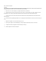
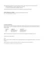
Digi International, Inc.
11001 Bren Road E.
Minnetonka, MN 55343
(612) 912-3444
Digi International GmbH
Domkloster 1
50667 Köln
Germany
+49 221 920-520
USER’S MANUAL
SYNC/570i-56
Synchronous Switched 56K - Leased Line
CSU/DSU Expansion Board
90000005A
Digi International is a registered trademark of Digi International Inc. The Digi logo is a trademark of Digi International Inc. All other
brand and product names are the trademarks of their respective holders.
© Digi International Inc. 1996 All Rights Reserved
Information in this document is subject to change without notice and does not represent a commitment on the part of Digi International.
Digi provides this document “as is”, without warranty of any kind, either expressed or implied, including, but not limited to, the implied
warranties of fitness or merchantability for a particular purpose. Digi may make improvements and/or changes in this manual or in the
product(s) and/or the program(s) described in this manual at any time.
This product could include technical inaccuracies or typographical errors. Changes are periodically made to the information herein; these
changes may be incorporated in new editions of the publication.
A Note Concerning Radio and Telephone Network Interference
FCC Part 15 Requirements
The ISA SYNC/570i-56 has been tested and found to comply with the limits for a Class B computing device pursuant to Subpart J of Part
15 of FCC rules.
Warning: Changes or modifications to this unit not expressly approved by the party responsible for compliance could void the user’s
authority to operate the equipment.
This device complies with part 15 of the FCC Rules. Operation is subject to the following two conditions: (1) This device may not cause
harmful interference, and (2) this device must accept any interference received, including interference that may cause undesired
operation.
However, there is no guarantee that radio interference will not occur in a particular installation. If this equipment does cause harmful
interference to radio or television reception, which can be determined by turning the equipment off and on, the user is encouraged to try
to correct the interference by one or more of the following measures:
Reorient or relocate the receiving antenna.
Increase the separation between the equipment and receiver.
Connect the equipment into an outlet on a circuit different from that to which the receiver is connected.
Consult the dealer or an experienced radio/TV technician for help.
If these measures fail to eliminate the interference, the user should contact either the distributor or an experienced radio/television
technician for further suggestions. The user may also find the booklet, How to Identify and Resolve Radio/TV Interference Problems
(prepared by the FCC) helpful.
This booklet is available from the U.S. Government Printing Office, Washington, DC 20402, Stock No. 004-000-00345-4.
SHIELDED CABLES MUST BE USED ON THE V.35/EIA-232 PORT TO REMAIN IN COMPLIANCE WITH PART 15 OF
THE FCC RULES.
Declaration of Conformity
(in accordance with FCC Dockets 96-208 and 95-19)
Manufacturer’s Name:
Digi International
Corporate Headquarters:
11001 Bren Road East
Minetonka, MN 55343
Manufacturing Headquarters: 10000 West 76th Street
Eden Prairie, MN 55344
Digi International declares, that the product:
Product Name:
Model Numbers:
SYNC/570i-56
50000563-01
50000564-01
to which this declaration relates, meets the requirements specified by the Federal Communications Commission as
detailed in the following specifications:
Part 15, Subpart B, for Class B Equipment
FCC Docket 96-208 as it applies to Class B personal
Computers and Peripherals
The product listed above has been tested at an External Test Laboratory certified per FCC rules and has been found
to meet the FCC, Part 15, Class B, Emission Limits. Documentation is on file and available from the Digi
International Homologation Department.
50000563-01
50000564-01
Tested To Comply
With FCC Standards
FOR HOME OR OFFICE USE
FCC Part 68 Requirements
This equipment complies with Part 68 of the FCC rules. The FCC registration number for this equipment is located on the PC card. If
requested, provide this number to the telephone company.
An FCC compliant telephone cord and modular plug is provided with this equipment. This equipment is designed to be connected to the
telephone network or premises wiring using a compatible modular jack which is Part 68 compliant.
If this equipment causes harm to the telephone network, the telephone company may temporarily discontinue service. Advance
notification will be given if possible; otherwise, notification will be given as soon as possible. The telephone company will advise the
customer of the right to file a complaint with the FCC.
The telephone company may make changes in its facilities, equipment, operations, or procedures that could affect the proper operation of
this equipment; advance notification and the opportunity to maintain uninterrupted service is given.
The following information may be required when applying to the local telephone company for leased line facilities:
Service
Type
56 kbps Digital Interface
64 kbps Digital Interface
Digital Facility
Interface Code
04DU5-56
04DU5-64
Service Order
Code
6.0 F
6.0 F
USOC
Jack
RJ48S
RJ48S
If trouble is experienced with this equipment, please contact Digi International for repair or warranty information. If the equipment is
causing harm to the telephone network, the telephone company may request that you disconnect the equipment until the problem is
resolved.
The equipment contains no user serviceable parts.
Canada
This equipment complies with part CS03 of the Canadian Department of Communication rules. Digi’s SYNC/570i-56 connects directly
to off-premise Common Carrier facilities via a DDS 4-wire service.
Notice: The Canadian Department of Communications label identifies certified equipment. This certification means that the equipment
meets certain telecommunications network protective operational and safety requirements. The Department does not guarantee the
equipment will operate to the user’s satisfaction.
Before installing this equipment, users should ensure that it is permissible to be connected to the facilities of the local
telecommunications company. The equipment must also be installed using an acceptable method of connection. In some cases, the
company’s inside wiring associated with a single line individual service may be extended by means of a certified connector assembly
(telephone extension cord). The customer should be aware that compliance with the above conditions may not prevent degradation of
service in some situations.
Repairs to certified equipment should be made by an authorized Canadian maintenance facility designated by the supplier. Any repairs or
alterations made by the user to this equipment, or equipment malfunctions, may give the telecommunications company cause to request
the user to disconnect the equipment.
Users should be aware for their own protection that the electrical ground connections of the power utility, telephone lines and internal
metallic water pipe system, if present, are connected together. This precaution may be particularly important in rural areas.
Caution: Users should not attempt to make such connections themselves, but should contact the appropriate electric inspection authority,
or electrician, as appropriate.
This Class B digital apparatus meets the requirements of the Canadian Interference Causing Equipment Regulations.
Cet appareil numerique de la classe B respecte toutes les exigences du Reglement sur le materiel brouilleur du Canada.
Underwriters Laboratory
The Digi SYNC/570i-56 is certified by Underwriters Laboratories, Inc. to UL 1950 and CSA 22.2 No. 950.
1.
Introduction......................................................................................... 1
CSU/DSU Features...........................................................................2
V.35/EIA-232 Port Features .............................................................2
Specifications...................................................................................2
2.
Checking Your Package Contents.........................................................3
3.
Installation ...........................................................................................5
Step 1. Set Up the Main Board ............................................................5
Step 2. Set Up Daughterboard..............................................................9
Step 3. Install In Computer................................................................12
Step 4. Configure the Micro Channel SYNC/570i..............................13
Step 5. Other ISA Card Set-up Options..............................................15
4.
Diagnostics.........................................................................................17
5.
Operation ...........................................................................................21
Switched 56K/DDS Telco Interface................................................21
V.35/EIA-232 Selectable Interface .................................................22
6.
In Case of Trouble ..............................................................................25
Appendix A: Protecting Your Equipment and Data..................................29
Electrical Surge and Power Protection ................................................29
Grounding Techniques .......................................................................30
Static Protection .................................................................................30
Appendix B: AT Commands....................................................................33
Appendix C: S Registers ..........................................................................39
Appendix D: AT Responses .....................................................................43
Appendix E: CSU/DSU Tests...................................................................45
Index ......................................................................................................49
1.
Switched 56K - Leased Line CSU/DSU daughterboard ........................9
2.
Jumper positions for V.35 and EIA-232.............................................10
3.
DIP switch block ...............................................................................11
4.
Female loopback connector wiring diagrams .....................................18
5.
Switched 56K/DDS RJ-45 Telco Interface .........................................21
6.
Board DB-25 female connector pinout and pin assignments...............22
7.
Cable DB-25 male connector pinout and pin assignments..................23
8.
V.35 male connector pinout and pin assignments ..............................24
9.
LL/TP (Local Loopback with Test Pattern) ........................................45
10.
LL (Local Loopback) .........................................................................46
11.
RT (Remote Terminal) ......................................................................46
12.
RL (Remote Loopback)......................................................................47
13.
RL (Remote Loopback) with Test Pattern (TP) ..................................47
The Digi SYNC/570i-56 is a high-performance expansion board for ISA or Micro Channel computers. This two port card
includes an integrated CSU/ DSU function for one port and a jumper configurable V.35/EIA-232 interface for the second
port. Each board assembly and connector package is supplied with all the hardware and software needed for a complete
board installation.
The Hitachi HD64570 Serial Communications Adapter (SCA) provides a highly-integrated advanced communications
subsystem for the SYNC/570i-56. It further maximizes synchronous communications performance by using protocolspecific features to minimize driver overhead.
The onboard memory of the SYNC/570i-56 is directly addressable by both the system and the SCA’s DMA. Programinitiated DMA transfers operate at DMA/memory speed independent of other system activity. This architecture provides low
system overhead and high performance.
The SYNC/570i-56 V.35 port communicates at T1/E1 line speeds up to 2.5 Mbps. Each HD64570 chip supports two
synchronous/asynchronous ports and four channels of DMA as well as interrupt and timer logic.
The CSU/DSU supports Clear Channel 64K, Leased Line 56K and Switched 56K service. In addition to providing Digital
Data Service (DDS) operation, the SYNC/570i-56 can serve as a limited distance modem providing full-duplex synchronous
communications over privately owned 4-wire, unloaded, twisted pair cable. The CSU/DSU Telco interface is a standard RJ45 8-pin jack. The V.35/EIA-232 port is a standard DB-25 connector.
The optional OEM software lock ensures that OEM software will operate only with OEM-supplied boards.
SYNC/570i-56 includes SurgeBlock™, which is designed to protect the board and the computer in which it is installed
against damage from data line surges.
Multiple SYNC/570i-56 ISA boards may share a common memory window. Micro Channel boards may share a common
interrupt request line.
CSU/DSU Features
• AT&T Specification 62310 compliance
• AT Command Set configurable
• Switched 56K or leased line configurable
• Clear Channel 64K
• LED indicators for
No Signal/Out of Service
Test Mode
TXD/RXD
• Configurable CSU/DSU status control lines
• V.54 remote loopback
• Surge and power cross protection
V.35/EIA-232 Port Features
• Independent operation from CSU/DSU port
• Hardware selectable
• V.35 serial data rates up to 2.5Mbits/second
• EIA-232 serial data rates up to 150Kbits/second
• Transient surge protection
Specifications:
Power Requirements: 458mA @ +5 VDC ± 5%
Switched 56K CSU/DSU 34mA @ -5 VDC ± 5%
24mA @ +12 VDC ± 5%
24mA @ -12 VDC ± 5%
Operating Temperature: 10-55° C
Relative Humidity: 5-90%, noncondensing
Altitude: 0 to 12,000 feet
Compliance: AT&T Technical Publication 62310
AT&T Technical Publication 41458
CSU/DSU Transmit Pair
Output Impedance: 135 ohm ± 10%
Output Pulse: 50 ± 5%
Output Amplitude: 2.8V ± 0.1V
CSU/DSU Receive Pair
Impedance: 135 ohm ± 10%
Input Levels: Maximum line loss of 43db
After opening the shipping box, check the contents.
WARNING
Leave the board in its protective anti-static bag until installation. When installing or removing boards, always use adequate
precautions (such as a grounding strap) to prevent electrostatic damage.
• SYNC/570i-56
• One 6-foot, Telco cable
• Telco loopback connector
• Information packet, including
-User’s manual
-Diagnostic diskette
-Customer Information Packet
The following cables are also available from Digi:
• EIA-232 interface cable – DB-25 to DB-25, male-to-male cable
• V.35 interface cable – DB-25 to V.35, male-to-male cable
The appropriate loopback connector is included in the cable package.
Step 1. Set Up the Main Board
Before installing the SYNC/570i-56 in an ISA system, you must set the I/O address.
NOTE
If you are installing the SYNC/570i-56 in a Micro Channel system, skip this step. Continue with the daughterboard configuration as
described in Step 2.
Set the multi-segment switch on the main board. The setting of the switch selects the starting address of the block of I/O
locations which the
SYNC/ 570i-56 uses.
The SYNC/570i-56 is shipped with a setting of 300H.
Diagrams of commonly used I/O address switch settings begin on the following page.
NOTE
All I/O addresses mentioned in this manual are in hexadecimal format.
Commonly Used I/O Address SYNC/570i-56 Switch Settings
Step 2. Set Up Daughterboard
There are two configuration options that you must set properly on the daughterboard:
• Interface port set via two blocks of jumpers, see below
• CSU/DSU powerup – set via a DIP switch, go to Page 11
The locations of the jumper sets and the DIP switch are shown on the figure below.
Figure 1, Switched 56K - Leased Line CSU/DSU daughterboard
Interface Port Selection
The selectable interface port is hardware configurable via two jumper sets on the daughterboard.
NOTE
When disconnecting the daughterboard in order to set the jumper, use adequate precautions (such as a grounding wrist strap
that is connected to earth ground) to prevent electrostatic damage.
Set the jumpers for the correct interface as described below.
a.
Remove the metal screws (from the host side) which secure the daughterboard to the motherboard.
b. Pull the daughterboard from the motherboard. (There is one connector holding the daughterboard. Do not use a
twisting motion.)
c. Install the jumper for the correct interface. Refer to Figure 1 for the location of the jumper sets. Each jumper set on the
daughterboard has 3 rows of 5 pins.
V.35
When the jumpers are on the top 2 rows of pins, the connectors interface with V.35 devices.
EIA-232
When the jumpers are on the bottom 2 rows of pins, the connectors interface with EIA-232 devices.
The position of the jumper block shown in Figure 2 is upright with the small 1 at the upper left corner.
Figure 2, Jumper positions for V.35 and EIA-232
V.35
EIA-232
d. Reconnect the daughterboard to the motherboard by matching the connectors and screw wells. Push the
daughterboard onto the motherboard and replace the screws.
CSU/DSU Powerup Configuration
The DIP switch, that configures the initial powerup of the CSU/DSU, can be changed with the daughterboard connected to
the motherboard.
The initial powerup configuration of the CSU/DSU is determined by the DIP Switch settings. This configuration can be
overwritten by AT commands. (Refer to Appendix B for AT commands.)
Refer to Figure 1 for the switch block location. This switch can be changed without separating the daughterboard from the
motherboard. With the boards connected, the OFF label on the switch block is not visible. OFF is away from the base of the
daughterboard, toward the motherboard.
DIP Switch
OFF
1
Leased Line
2
56K Rate
3
Slave (DDS) Timing
4
&D0 Mode
DTR off: Command Mode
DTR on: Data Mode
switched call
ON
Switched Line*
64K Clear Channel Rate
Internal Timing
&D2 Mode
Dropping DTR terminates a
*Selecting a switched line will automatically choose a 56K rate with slave timing
Figure 3, DIP switch block
Step 3. Install In Computer
WARNING
Turn off power to your computer and disconnect the power cord. Inserting a board into the system with power applied could
damage the system, the board, or both. Such abuse will void your warranty.
a.
Remove the cover of the computer (see computer manufacturer’s instructions).
b. Determine which 16-bit slot your SYNC/570i-56 will occupy. Loosen the thumb screw (Micro Channel) or remove
the hold-down screw at the top of the blank card bracket of the slot and remove the blank card bracket (ISA).
c. Insert the SYNC/570i-56 and switched 56K board assembly into the mating motherboard socket. Push the board
firmly into place.
d. Secure the board by tightening the thumb screw or replacing the board hold-down screw that was removed in Step 3b
above.
e.
Replace the computer cover and reconnect the power cord.
f.
Power-up the computer. The NS LED displays a steady red light to indicate that no lines are connected.
g.
Complete the software configuration of the board (Step 4 or Step 5).
h.
Run the diagnostics described in Chapter 4.
Step 4. Configure the Micro Channel SYNC/570i-56
NOTE
Skip this step if you have an ISA card.
Configure the SYNC/570i-56 through your computer’s Micro Channel Programmable Options Select (POS) system, using
data from the Digi Adapter Definition File (ADF) on the diagnostic diskette. This system uses hardware registers, selected
and loaded through software, to assign system resources to an expansion board. Each type of expansion board has its own
unique code number, assigned in conjunction with the computer manufacturer, which identifies it to the system. (If you
cannot determine the proper setup information, check with an operating system vendor or Digi Customer Support.)
NOTE
Refer to your computer system documentation for information on the
a.
Programmable Option Select.
Install the board as described in Step 3.
b. Determine which .ADF file on the Digi Diagnostics Diskette you need for configuration. Refer to the note below for
an explanation of the files. If necessary, copy and rename the file you need.
NOTE
The diagnostics diskette actually contains three ADF files: @6163.ADF, @6163.AD1, and @6163.AD2. The files @6163.ADF
and @6163.AD1 are identical. (This ADF file is the one that is copied to your reference diskette.)
The .ADF and .AD1 files contain the most commonly used configurations.
The @6163.AD2 file contains every possible option for configuration.
If you wish to use the .AD2 file, you must copy the file to the reference diskette as @6163.ADF. Since the reference diskette will
copy only the .ADF file, copy the file to another diskette and rename.ADF.
it
c. Reboot the computer with the backup copy of your computer system's reference diskette. The computer will show error
165 and beep twice. Continue as instructed.
d. Follow the instructions shown on the screen to select the mode necessary to manually set the configuration—do not
use the automatic configuration. (The instructions for manual configuration will vary for computers made by different
manufacturers.)
e.
When you are prompted to copy the new adapter files, insert the Digi Diagnostics Diskette.
f.
Press ENTER. The computer will read the @6163.ADF file.
g.
At the prompt, remove the diagnostics disk and reinsert the reference diskette.
h.
Press ENTER. The file @6163.ADF copies to the reference disk.
i.
Follow the instructions shown on the screen to set or change the configuration for the Digi SYNC/570i-56.
j.
Select the I/O address, memory address, and IRQ from the list of addresses and interrupt lines shown.
k.
Follow the instructions to save the configuration you have chosen and to exit the program.
l.
Remove the copy of the reference diskette.
Step 5. Other ISA Card Set-up Options
The memory address and interrupt line (IRQ) are software configurable via either your operating system or an installable
driver. You will be asked to specify a 16KB memory window location.
Jumper JP1 on the ISA SYNC/570i-56 controls the Fast Select circuitry on board. The SYNC/570i-56 is shipped with a
jumper connecting pin 2 and pin 3 of JP1. This setting allows the boards to work with any combination of 8 or 16 bit video
and/or network cards supporting Fast Select. When pins 1 and 2 are jumpered, the board must be installed in a 128KB
paragraph which contains only 16 bit cards. The default setting (pins 2 and 3 jumpered) works in most computers and
should not be changed without verification from Digi Technical Support.
The diagnostics diskette in conjunction with the loopback connector is designed to verify correct installation. Make a copy
of this disk and store the original. Should a problem develop in the future, you can run the diagnostics to locate the
problem.
NOTE
Before beginning the diagnostics program, make sure no devices are connected to the SYNC/570i-56 ports. When prompted by
the diagnostics program, install the loopback connector.
Your system must be running DOS in order to use the diagnostics program.
The diagnostics tests one board at a time. Although the active board by default is the ISA board at the highest I/O address or
the Micro Channel board at the highest slot number, you may change the active board. The screen header indicates the
active board and its address.
The tests will fail if there is an address or interrupt conflict. If the diagnostics cannot determine your switch settings, there
is probably a conflict. In this case, try other address and/or interrupt settings.
For an ISA system, the diagnostics program displays IRQ, the base memory address, and the base I/O address. You may
modify the address and IRQ selections from the diagnostics. The IRQ must be active, and you must select a non-zero
address. If you cannot determine a setting, call Digi Customer Support for assistance.
For a Micro Channel system, the diagnostics program displays the current POS registers which identify the IRQ, the base
memory address, and the base I/O address. If any of these parameters need to be changed, repeat the procedure in beginning
on Page 13. If you cannot determine a setting, call Digi Customer Support for assistance.
1.
Insert the diagnostic disk into Drive A.
2.
3.
Type A:SYNC570 to start the diagnostics.
Follow the instructions on the screen.
When IRQ and address selection are acceptable, the adapter memory is tested. The test does write/verify at every
location with word accesses only. Each 16K memory window is selected and tested independently. Address and data buses
are tested separately.
The program then runs a window uniqueness test. A different, single word is written to each of the eight 16K
windows; then the test reads each window to verify that the windows are indeed unique.
When prompted, install the Telco loopback connector on the Telco connector. The wiring diagram for the loopback
connectors is shown below. The diagnostics program tests the control and data lines. When the line 1 tests are complete,
install the single channel loopback connector onto the V.35/EIA-232 cable connector. The tests will be repeated for line 2.
The control line loopback tests RTS to CTS, and DTR to DSR to DCD. The data loopback test is the default single channel
chained-block DMA transfer mode test.
Figure 4, Female loopback connector wiring diagrams
V.35/RS 232
Telco
The diagnostics program also tests the ability of the card to generate interrupts by way of internal data loopbacks. It
tests all found ports. For example, a 4 port board will prompt you to move the loopback connector when performing the
external data and control signal tests.
The internal and external tests are run at the maximum supported bit rates for their respective interfaces. On the
internal tests, all available channels are run simultaneously at the maximum bit rate to help resolve arbitration and memory
bandwidth issues.
If the diagnostics are successful, connect the appropriate interface cables. The SYNC/570i-56 provides two ports:
• Switched 56K/DDS Telco interface with RJ-45 keyed 8-pin jack
• V.35/EIA-232 selectable interface with DB-25 connector
The cables and connectors for each interface are described below and on the following pages.
Switched 56K/DDS Telco Interface
The Telco interface is an RJ-45 keyed 8-pin jack. The jack pinout is shown below.
Figure 5, Switched 56K/DDS RJ-45 Telco Interface
CSU/DSU LED Indicators
During operation two bicolor LEDs show the status of the CSU/DSU. The location of the two bicolor LEDs is shown in
Figure 1 on Page 9. The No Rx Signal/Receive Data LED is labeled NS/RD, and the Test Mode/Transmit Data LED is
labeled TM/TD.
LED State
Red
Green
Off
NS/RD LED
Loss of Telco Rx Signal
DTE Rx Data active
DTE Rx Data inactive
TM/TD LED
CSU/DSU in Test Mode
DTE Tx Data active
DTE Tx Data inactive
When you connect the cable, both LEDs will be off. If the LEDs are blinking green, data traffic is present.
V.35/EIA-232 Selectable Interface
NOTE
Refer to Pages 9 and 10 for information about configuring the jumpers on the daughterboard to make the correct interface
selection.
The pinout and pin assignments for the DB-25 connector on the SYNC/570i-56 are shown below.
Figure 6, Board DB-25 fe***00000male connector pinout and pin assignments
The cable included in the SYNC/570i-56 EIA-232 package has a DB-25 male connector on the board end, and a DB-25
male connector on the peripheral end. The connector provides an EIA-232-D interface for serial data transmission and
reception. The pinout and pin assignments for the DB-25 connector are shown in Figure 7.
Figure 7, Cable DB-25 male connector pinout and pin assignments
The cable included in the SYNC/570i-56 V.35 package has a DB-25 male connector on the board end, and a V.35 male
connector on the peripheral end. The pinout and the pin assignments for the male V.35 connector are shown in Figure 8.
Figure 8, V.35 male connector pinout and pin assignments
A
B
C
D
E
F
H
P
R
S
T
U
V
W
X
Y
AA
CGND
GND
RTS
CTS
DSR
DCD
DTR
TXD(A)
RXD(A)
TXD(B)
RXD(B)
TXCLKOUT(A)
RXCLK(A)
TXCLKOUT(B)
RXCLK(B)
TXCLKIN(A)
TXCLKIN(B)
WARNING
Make sure your computer is turned off before installing or removing boards. When installing or removing boards, always use
adequate precautions (such as a grounding strap) to prevent electrostatic damage.
Test your SYNC/570i-56 using the diagnostics disk provided. If the SYNC/570i-56 passes all the tests, the problem is
probably elsewhere.
The symptoms of particular problems may vary between operating systems. Common problems are listed below.
Address/Interrupt Conflicts
All devices in your system must have unique addresses that must not overlap. The memory location must be outside
the caching memory range. If you think you have a conflict problem, try alternate settings.
Inconsistent Baud Rate
The baud rate and other parameters chosen via the operating system must be the same for the SYNC/570i-56 and the
peripherals connected to it.
No Handshaking Signals
Some peripheral devices may need some or all of the handshaking signals that SYNC/570i-56 supports.
Incomplete or Incorrect Installation
Some operating systems require that an installation procedure be run before SYNC/570i-56 is recognized.
Refer to your operating system user's manual. Verify correct SYNC/570i-56 hardware installation.
Improper Grounding
Make sure that every component in your system is properly grounded. Differences in ground potential between your
computer and terminals can damage equipment.
Whom To Call
If your board fails the diagnostics or you are unable to isolate the problem, call Digi Technical Support (800-344-4273)
anytime between 8 a.m. and 6 p.m. Central Time (Monday through Friday). We can give you suggestions for things to try.
Please have the following information ready when you call:
Fill in information here
• Computer make
• Computer model number
• Operating system
• Which Digi board you are using
Serial number
Revision number
• Type of hard drive in your system
• Type of video card in your system
• Type of tape backup in your system
• Failure symptoms
• Results of diagnostics
• Whether the board has worked before
(was it installed successfully?)
• Dealer/store where you purchased
your Digi board
______________
______________
______________
______________
______________
______________
______________
______________
______________
______________
______________
If You Must Return a Board
Sometimes our boards do have problems and have to be returned for service. In this case, you’ll need to call us for an RMA
number. You must have an RMA number to return a board to Digi. The RMA number must appear on the outside of the
package. Before calling for the number, make sure you can answer the following questions:
1. Where did you buy your board? If you bought from a dealer, you should go through the dealer to return the board. If
you bought it from Digi, you can deal directly with us for repair.
2.
What is your board’s serial number, revision level number, and date of purchase?
3. Have you followed the checklist at the beginning of this chapter and tried all of the steps? We’ve found that these
procedures eliminate most problems encountered during installation.
4.
Have you contacted the dealer from whom you originally purchased the board for his advice and assistance?
Your Digi board is one of the most reliable parts of your networked system. If you purchase a board from us and it does not
work in your application, or if you decide not to keep it for any reason during the first 30 days, we will refund your money.
But remember, we are here to help in any case—because our ultimate goal is to keep your system up and running, and to
keep you a satisfied customer.
Electrical Surge and Power Protection
Lightning, electrical surges, and power fluctuations can damage your equipment and/or data through the power lines and/or
the serial data lines. When electrical storms occur, the most effective method of protecting your computer system is to
unplug your computer and peripherals, and disconnect all data and telephone lines.
To protect against lightning, electrical surges, and power fluctuations, Digi recommends uninterruptible power supplies
(UPS), power line filters, and surge protectors for every installation.
A UPS can provide protection from electrical surges and fluctuations in the power supplied to the computer. However, it
does little good to protect the main console if you have no protection on the other devices attached to the system. Power line
filters protect against electrical surges and transient spikes. Some filters even have a shutdown feature that drops power to
the device if voltage drops below a preset level. This prevents the spikes and surges caused by the typical “off and on”
electrical problems that occur during a thunderstorm. AC line filters should be used with all electrical devices connected to
a computer system, no matter how small or simple.
The interface cables themselves present another potential danger. Nearby lightning strikes can induce high-voltage surges
into the cables. Machinery, especially commercial machines with electric motors, often generates electrical noise that can be
picked up by cables and cause data errors or equipment damage. Digi includes SurgeBlock on every SYNC/570i-56.
SurgeBlock clips fast-rising peak voltages to help protect against spikes over twenty-five volts caused by lightning, static, or
induced voltage. For maximum protection we recommend surge suppressors on the peripheral end of all serial cables.
Cables running long distances and/or through electrically noisy areas are subject to noise pickup that can cause data errors
or equipment damage. Destructive power surges can also enter through modems via telephone connections. Filters made
specifically for this purpose should be included on all telephone line connections.
Using a receptacle for only the computer and terminal also protects against data errors or equipment damage. Sharing the
receptacle with noise-producing devices such as fax machines, printers, calculators, and heaters may allow noise pickup.
Grounding Techniques
Many terminals and computers are dependent on earth ground to set a reference for signal ground. Improper grounding or
differences in ground potential between your computer and terminals can damage your equipment or even create a safety
hazard. Consequently, you should make sure that every component in your system is properly grounded.
Connect your computer and all terminals and other peripherals to three-pronged grounded receptacles, making sure that the
receptacles are wired
properly. If you must use three-prong to two-prong adapters, make sure that the adapter ground tabs are properly grounded.
A proper chassis ground guarantees that no dangerous voltages exist on terminal frames. Proper grounding also helps
cancel noise that can otherwise be induced on the frame or equipment.
Local electrical codes may also dictate special grounding arrangements. Your electrician can make sure that your
installation complies with all applicable codes. If you have any doubt about the integrity of the grounding system in your
location, have the system checked by a licensed electrician.
Static Protection
Your computer's case not only houses its family of computer components, but it also protects these sensitive electronic
components from stray magnetic (EMI) and electrical (RFI, static) fields.
WARNING
Using proper static control methods is essential whenever you use, move, or open your computer for modifications.
Make sure that you are working in a static-controlled area which includes at least a conductive benchtop mat or chair mat
that is electrically connected to earth ground. Conductive wrist straps in conjunction with ground cords provide extra
protection for handling electronic components. Always store and/or move individual printed circuit boards in a conductive
bag. Consult your local electronics or office supply distributor for static control products.
If you would like an overview of grounding and static protection theories and techniques, you can obtain a copy of Federal
Information Processing Standards Publication 94: Guideline on Electrical Power of ADP Installations. This booklet is
available from the National Technical Information Service, U.S. Department of Commerce, Springfield, VA 22161
703/487-4650.
The following configurations are controlled by AT commands:
Mode :
Rate:
Loopbacks:
RTS:
CTS:
DCD:
DSR:
Switched / Leased
56K / 64K Clear Channel
Local Loopback
Remote Terminal
Normal (follow DTE’s RTS)
Forced High
Normal Mode (follows RTS)
Off during No Signal Condition
Normal Mode (Off during Control Mode Idle (CMI)
Forced High
Off during No Signal Condition condition
Forced High
Refer to Appendix E, “CSU/DSU Tests.”
The AT codes and commands are shown below and on the following page.
* - indicates powerup default
•- indicates powerup configuration is defined by DIP switches
Code
AT
D
H
I
I1
I2
O
Sr?
Sr=n
Code
V0
V1 *
&C0
&C1 *
&C2
&D0 •
&D1
&D2 •
&F0
&F1
&F2
&L0
&L1
&N0 •
&N1 •
&R0 *
&R1
&S0
&S1 *
&T0
&T1
Command
Related S Register
Attention command
Dial Telephone number
Dial Modifiers
0-9
Numbers to dial
,
Pause 2 seconds
Hang-up Call
Display product code
Display ROM checksum
Display Firmware Revision Level
Return to Data mode
Display register r value
Set register r to value n
Command
Related S Register
Send numeric responses
S14
Send word responses
S14
Force DCD on
S21
Normal DCD
S21
Normal DCD; CTS off when DCD off
S21
DTR off: Cmd mode; DTR on: Data mode
S21
Dropping DTR enters command mode
S21
Dropping DTR terminates call
S21
Factory Configuration 0 - 56K leased line
Factory Configuration 1 - Switched 56K line
Factory Configuration 2 - Clear Channel 64K leased
•
Switched 56K Service
S27
•
Leased Line
S27
56K rate
S27
64K rate
S27
Normal RTS
S21
Force RTS on
S21
Force DSR on
S21
Normal DSR
S21
End test in progress
Local Loop (LL)
S16
&T3
&T4 *
&T5
&T6
&T7
&T8
&T9
&X0 •
&X2 •
Remote Terminal (RT)
Enable Remote Loopback (RL)
S23
Disable Remote Loopback (RL)
Remote Loopback
Remote Loopback with Test Pattern
Local Loopback with Test Pattern
Test Pattern
Internal timing
S27
Slave timing
S27
S16
S23
S16
S16
S16
S16
AT
Attention characters
Every command line must begin with the attention characters “AT” and end with a carriage return (Hex 0D). The “AT”
command string must be less than 30 characters.
D
Dial command
The D command instructs the CSU/DSU to pulse dial a telephone number. The DSU must be in switched mode (&L0) in
order to dial. The format for the dial command is “ATD n” where n is the telephone number to dial including any dial
modifiers. After a number has been dialed call progression responses (CONNECT, NO ANSWER, etc.) will be sent to the
DTE.
H
Hang-up command
Sending an ATH command causes the switched 56k call to terminate.
I
Returns CSU/DSU information
This command returns information (in the form of an ASCII string) from the DSU/CSU followed by a valid command
response.
I or I0
Display product code
I1
Display ROM checksum
I2
Display Firmware Revision Level
O
This command returns the CSU/DSU to data mode if DTR control is configured for &D1 or &D2
Sr?
Read register number r
This command reads the decimal value of register r.
ATS0? reads the current value of register 0. A three character decimal number is returned (for example, 000, 014, 255)
followed by a valid command response.
Sr=n Store value n into register r
This command stores the decimal value n into register r.
ATS0=1 stores 1 into register 0.
V
Response format
This command instructs the DSU whether to respond to commands with words or numbers. The responses are described in
Appendix D on Page 43.
V or V0
DSU sends numeric responses
V1
DSU sends word responses
&C
DCD control
This command configures the DCD options
&C or &C0
Forces DCD on permanently
&C1
Normal DCD operation - DCD is on unless CSU is receiving control codes (powerup default)
&C2
Normal DCD operation - CTS is turned off if DCD is off
&D
DTR control
This command configures the DTR options.
&D or &D0
DTR off: command mode; DTR on: data mode. Answer incoming switched call if S0=1 (option
normally used for leased line mode).
&D1
Dropping DTR enters command mode. Return to data mode with “ATO” command or when a
switched call connects. Answer incoming switched call if DTR is on and S0=1.
&D2
Dropping DTR terminates switched call and enters command mode. Return to data mode with
“ATO” command or when a switched call connects. Answer incoming switched call if DTR is on and S0=1 (option
normally used for switched mode).
&F
Restore factory configuration profile
This command restores the following configuration profiles
&F or &F0
Restores factory profile 0
Leased line 56K, slave timing, normal RTS, DCD and DSR
&F1
Restores factory profile 1
Switched 56K line, answer incoming calls
&F2
Restores factory profile 2
Clear Channel 64K lease line, slave timing, normal RTS, DCD and DSR
&L
Dial or Leased line control
This command configures the DSU for switched or leased line operation (powerup configuration is defined by DIP switch 1)
&L or &L0
Selects a Switched 56K dial mode
&L1
Selects leased line
&N
Leased line rate configuration (powerup configuration is defined by DIP switch 2)
&N or &N0
Configure leased line rate to 56K
&N1
Configure leased line rate to 64K
&R
RTS/CTS control
This command configures the RTS options.
&R or &R0
Normal RTS - CTS follows RTS (powerup default)
&R1
Force RTS on - RTS is forced on to the DSU (CTS is on also)
(note: CTS operation can be effected by &C command.)
&S
DSR control
This command configures the DSR options.
&S or &S0
Force DSR on permanently
&S1
Normal DSR - DSR is on when all conditions are met for transmitting data (powerup default).
&T
Test configuration
&T or &T0
Stops the current test in progress
&T1
LL - Initiates the Local Analog Loopback test. The DSU/CSU performs a loopback close to the
Telco interface. Data is looped back from the DTE as well as the Telco line.
&T3
RT - Initiates the Remote Terminal loopback test. The DSU/CSU performs a loopback close to
the DTE interface. Data is looped back to the DTE as well as the Telco line.
&T4
Enable Remote Loopback (RL) - Allows the DSU/CSU to respond to a remote CSU’s (RL)
request (powerup default).
&T5
Disable Remote Loopback (RL) - ignore remote CSU’s RL request.
&T6
(RL) - Initiate a remote loopback test. This test verifies the local CSU, the remote CSU and the
telephone line.
&T7
Initiates RL/TP -Remote Loopback with a DSU/CSU generated 511 test pattern. At the end of the
test an error count is returned to the DTE followed by a valid command response. Anything other than an error count of 000
indicates data errors were received
&T8
Initiates LL/TP - Local Loop with a DSU/CSU generated 511 test pattern.At the end of the test
an error count is returned to the DTE followed by a valid command response. Anything other than an error count of 000
indicates data errors were received.
&T9
Initiates TP - An internally generated 511 test pattern is transmitted.
At the end of the test an error count is returned to the DTE followed by a valid command
response. Anything other than an error count of 000 indicates data errors were received. (Max count is 255.)
&X
timing control
This command configures the source of the TXCLK (powerup configuration is defined by DIP switch 3).
&X or &X0
Selects the DSU’s internal timing source.
&X2
Slave timing - Receive clock is the timing source.
S14
S16
S21
S23
S27
S0
Bit mapped
Bit mapped
Bit mapped
Bit mapped
Bit mapped
Auto answer
Read only
Read only
Read only
Read only
Read only
Read/Write
Register S0 - Auto answer
Range: 0 to 1
A value of 1 tells the CSU/DSU to answer incoming calls. A value of 0 tells the CSU/DSU to ignore incoming calls.
Register S14
Bit
0-2
3
4-7
Register S16
Bit
0
Bit mapped register
Function
Not used
Response
format
Not used
Value
0-number responses
1-word responses
Related command
V0
V1
Bit mapped register
Function
LL
1
Telco loopback
2
RT
3
RL from
remote DSU
Value
Related command
0-test disabled
&T1
1-test enabled
0-not in Telco loopback
1-in Telco loopback
0-test disabled
&T3
1-test enabled
0-not in RL
1-in RL
Register S16, continued
4
RL
5
RL/TP
6
LL/TP
7
TP
0-test disabled
1-test enabled
0-test disabled
1-test enabled
0-test disabled
1-test enabled
0-test disabled
1-test enabled
&T6
&T7
&T8
&T9
S21 register - Bit mapped register
Bit
0-1
2
3-4
Function
Not used
RTS/CTS
options
DTR options
5-6
DCD options
7
DSR options
Value
Related command
0-normal RTS
1-permanent RTS
0 - DTR off: command mode
1 - dropping DTR enters
command mode
2 - dropping DTR terminates
switched call
3 - not used
0-force DCD on
1-normal DCD
2-normal DCD/CTS off
when DCD off
3-not used
0-force DSR on
1-normal DSR
&R0
&R1
&D0
&D1
&D2
&C0
&C1
&C2
&S0
&S1
S23 register - Bit mapped register
Bit
0
Function
RL enable/disable
1
Loss of Rx Signal
2 Out of Service (OOS)
3
4-7
Switched call status
Value
Related command
0-RL disabled
&T5
1-RL enabled
&T4
0-Rx Signal Present
1-Loss of Rx Signal
0-Normal Operation
1-OOS Signal Present
0-Call Disconnected
1-Call Connected
Not used
S27 register - Bit mapped register
Bit
0-1
2
Function
Not used
Line type
3
Not used
Value
Related command
0-Dial line
1-Leased line
&L0
&L1
0-internal timing
1-not used
2-slave timing
3-not used
0-56K
1-64K
&X0
S27 register, continued
4-5
Txclk timing
source
6
Leased line speed
7
Not used
&X2
&N0
&N1
These are the messages that the CSU/DSU sends to the DTE in response to an AT command. Whether a numeric response
or a word response is sent is determined by the V command. Each response is followed with an ASCII carriage return (Hex
0D) and an ASCII line feed (Hex 0A).
Numeric
0
1
2
3
4
5
6
Word
OK
CONNECT
RING
DISCONNECT
ERROR
NO WINK
NO ANSWER
Meaning
Valid command
Connection Made
Incoming ring detected
Call disconnected
Invalid command
No Wink received from CO
No Answer from far end
The following AT commands respond with an ASCII string terminated with a carriage return and a line feed, followed by a
valid command response (refer to the above responses):
•I
• Sr?
• &T0 (with TP active)
Use the AT commands to send test patterns through loopback paths in order to test the operation of network components.
The TM LED is on during a locally or remotely initiated test.
Local Loopback (LL) With Test Pattern (TP)
An LL/TP performs a self test of the CSU/DSU. A 511 bit test pattern from the CSU/DSU pattern generator passes through
the the transmit logic (Tx) and the receive logic (Rx) to the test pattern detector.
Figure 9, LL/TP (Local Loopback with Test Pattern)
Local Loopback (LL)
Data received from the network passes through the line receiver and loops back through the line driver to the network. The
LL is bilateral. Data from the DTE passes through the the transmit logic (Tx) and the receive logic (Rx) back to the DTE.
Figure 10, LL (Local Loopback)
Remote Terminal (RT)
Data from the network passes through the interface, the transmit and receive logic, back to the network.
Figure 11, RT (Remote Terminal)
Remote Loopback (RL)
Upon receiving a RL signal from the local CSU/DSU, the remote CSU/DSU enters RT configuration. The local DTE can
then transmit data to determine if the local CSU/DSU, the DDS network, and the remote CSU/DSU are functional.
Figure 12, RL (Remote Loopback)
Remote Loopback (RL) with Test Pattern (TP)
RL with TP is similar to RL except that an internally generated 511 test pattern is used for data.
Figure 13, RL (Remote Loopback) with Test Pattern (TP)
address/interrupt conflicts, 25
ADF files, 13, 14
AT commands, 11, 33, 43, 45
AT responses, 43
baud rate (inconsistent), 25
cables 3, 21, 22, 23, 30
connectors, 10, 21, 22, 23, 24
CSU/DSU, 1, 2, 9, 21, 35, 39, 43, 45, 46
CSU/DSU LED Indicators, 21
CSU/DSU powerup, 9, 11, 33, 36, 37, 38
DB-25 connector, 1, 3, 21, 22, 23
EIA-232, 1, 2, 3, 10, 18, 20, 22, 23
EIA-232 connector, 18, 22
grounding, 26, 30, 31
handshaking signals, 25
I/O address (ISA) , 5, 6-8, 17
I/O address (Micro Channel), 14, 17
interface port selection, 9, 10, 21, 22
IRQ (ISA), 15, 17, 18
IRQ (Micro Channel), 14, 17, 18
jumpers, 9, 10, 15, 22
LED Indicators, 12, 21, 22, 45
LL Test, 46
LL/TP Test, 45
loopback connector, 3, 17, 18, 19
loopback tests, 18, 19, 33, 36, 37, 38, 39, 45, 46, 47
memory address ISA), 15, 17
memory address (Micro Channel), 14, 17,
NS/RD LED,12, 21
POS registers, 17
powerup configuration, 11, 33, 36, 37, 38
RJ-45, 21
RL Test, 47
RL/TP Test, 47
RT Test, 46
S Registers, 39
selectable interface, 9, 10, 21, 22
switch settings (I/O address), 5, 6-8
switch settings (CSU/DSU powerup configuration), 11
Telco cable, 3
Telco connector, 18
Telco interface, 1, 21, 37
Telco loopback connector, 3, 18
TM/TD LED, 12, 21, 45
V.35, 1, 2, 3, 10, 18, 22, 23
V.35 connector, 3, 18, 22, 23, 24