1
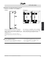
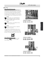
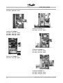
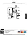
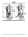
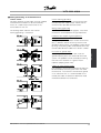
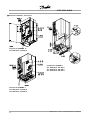
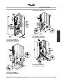
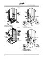
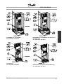
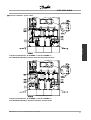
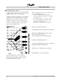
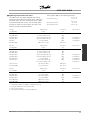
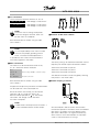
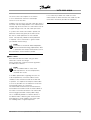
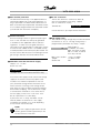
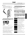
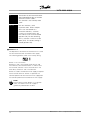
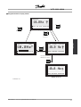
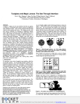
VLT® 8000 AQUA
■ Mechanical installation
Please pay attention to the requirements
that apply to integration and field mounting
kit, see the below list. The information given
in the list must be observed to avoid serious damage
or injury, especially when installing large units.
The adjustable frequency drive must be
installed vertically.
All units require a minimum space above and
below the enclosure.
Installation
The adjustable frequency drive is cooled by means
of air circulation. For the unit to be able to release its
cooling air, the minimum distance over and below the
unit must be as shown in the illustration below.
To protect the unit from overheating, it must be ensured
that the ambient temperature does not rise above the
max. temperature stated for the adjustable frequency
drive and that the 24-hour average temperature is not
exceeded. The max. temperature and 24-hour average
can be seen from the General Technical section.
When installing the adjustable frequency drive on
a non flat surface, i.e. a frame, please consult
the instruction, MN.50.XX.YY.
If the ambient temperature is in the range of 45° C
- 55° C, derating of the adjustable frequency drive
will be required in accordance with the diagram in
the Design Guide. The service life of the adjustable
frequency drive will be reduced if no allowance is made
for the derating for ambient temperature.
■ Installation of VLT 8006-8352
All AFDs must be installed in a way that
ensures proper cooling.
Cooling
MG.80.A6.22 - VLT is a registered Danfoss trademark
47
VLT® 8000 AQUA
Side by side/flange by flange
All AFDs can be mounted side by side/flange by flange.
d [mm/in]
Comments
Compact (all enclosure types)
VLT 8006-8011, 380-480 V
VLT 8002-8011, 525-600 V
100/3.9
100/3.9
Installation on a plane, vertical surface (no spacers)
VLT 8006-8032, 200-240 V
200/7.9
VLT 8016-8072 380-480 V
VLT 8102-8122 380-480 V
VLT 8016-8072 525-600 V
200/7.9
225/8.9
200/7.9
Installation on a plane, vertical surface (no spacers)
VLT 8042-8062, 200-240 V
VLT 8100-8300, 525-600 V
225/8.9
225/8.9
Installation on a plane, vertical surface (no spacers)
VLT 8152-8352, 380-480 V
225/8.9
Installation on a plane, vertical surface (spacers can be used). IP 54 filter
IP 54 filter mats must be changed when they are dirty.
mats must be changed when they are dirty.
48
MG.80.A6.22 - VLT is a registered Danfoss trademark
VLT® 8000 AQUA
■ Installation of VLT 8450-8600 380-480 V Compact IP
00/Chassis, IP 20/NEMA 1 and IP 54/NEMA 12
Side-by-side
All units in the above-mentioned series require a
minimum space of 400 mm (15.8 in) above the
enclosure and must be installed on a plane floor. This
applies to both IP 00/Chassis, IP 20/NEMA 1 and IP
54/NEMA 12 units.
Gaining access to VLT 8450-8600 requires a
minimum space of 605 mm (23.8 in) in front of the
AFD.
All IP 00/Chassis, IP 20/NEMA 1 and IP 54/NEMA 12
units in the above-mentioned series can be installed
side by side without any space between them, since
these units do not require cooling on the sides.
Installation
Cooling
■ IP 00 VLT 8450-8600 380-480 V
The IP 00/Chassis unit is designed for installation in a
cabinet when installed according to the instructions
MG.80.A6.22 - VLT is a registered Danfoss trademark
in the Installation Guide MG.56.AX.YY. Please note,
that the same conditions as for NEMA 1/ IP20
and IP54/NEMA 12 must be fulfilled.
49
VLT® 8000 AQUA
■ General information about electrical installation
■ High voltage warning
If more than one device is installed in cabinets, the
cabinet rear plate, which must be made of metal,
should be used as a common ground reference
plate. The metal cabinets of the different devices are
mounted on the cabinet rear plate using the lowest
possible HF impedance. This avoids having different
HF voltages for the individual devices and avoids the
risk of radio interference currents running in connection
cables that may be used between the devices. The
radio interference will have been reduced.
In order to obtain a low HF impedance, use the
fastening bolts of the devices as HF connection to
the rear plate. It is necessary to remove insulating
paint or similar from the fastening points.
The voltage of the AFD is dangerous
whenever the equipment is connected
to line. Incorrect installation of the motor
or the AFD may cause damage to the equipment,
serious personal injury or death. Consequently,
the instructions in this manual, as well as national
and local safety regulations, must be complied
with. Touching the electrical parts may be fatal even after disconnection from line:
Using VLT 8006-8062, 200-240 V wait at
least 15 minutes
Using VLT 8006-8072, 380-480 V wait at
least 15 minutes
■ Cables
Using VLT 8102-8352, 380-480 V wait at
Control cables and the filtered line cable should be
least 20 minutes
installed separate from the motor cables so as to avoid
Using VLT 8450-8600, 380-480 V wait at
interference overcoupling. Normally, a distance of
least 15 minutes
204mm (8 in) will be sufficient, but it is recommended
Using VLT 8002-8006, 525-600 V wait at least 4 minutes
to keep the greatest possible distance wherever
Using VLT 8008-8027, 525-600 V wait at
possible, especially where cables are installed in
least 15 minutes
parallel over a substantial distance.
Using VLT 8032-8300, 525-600 V wait at
least 30 minutes
With respect to sensitive signal cables, such as
telephone cables and data cables, the greatest
NOTE
possible distance is recommended with a minimum
It is the user’s or certified electrician’s
of 1m (3 ft) per 5m (15 ft) of power cable (line
responsibility to ensure correct grounding
and motor cable). It must be pointed out that
and protection in accordance with applicable
the necessary distance depends on the sensitivity
national and local codes and standards.
of the installation and the signal cables, and that
therefore no precise values can be stated.
■ Grounding
The following basic issues need to be considered
when installing an AFD.
•
•
Safety grounding: Please note that the
AFD has a high leakage current and must be
grounded appropriately for safety reasons.
Apply local safety regulations.
High-frequency grounding: Keep the ground
wire connections as short as possible.
If cable jaws are used, sensitive signal cables
are not to be placed in the same cable jaws as
the motor cable or brake cable.
If signal cables are to cross power cables, this should
be done at an angle of 90 degrees.
Remember that all interference-filled in- or
outgoing cables to/from a cabinet should be
shielded/armored or filtered.
Connect the different ground systems at the lowest
■ Shielded/armored cables
possible conductor impedance. The lowest possible
The shield must be a low HF-impedance shield. This is
conductor impedance is obtained by keeping the
ensured by using a braided shield of copper, aluminium
conductor as short as possible and by using the
greatest possible surface area. A flat conductor, for
example, has a lower HF impedance than a round
conductor for the same conductor cross-section CVESS.
50
MG.80.A6.22 - VLT is a registered Danfoss trademark
VLT® 8000 AQUA
Installation
or iron. Shield armor intended for mechanical
protection, for example, is not suitable.
MG.80.A6.22 - VLT is a registered Danfoss trademark
51
VLT® 8000 AQUA
■ Extra protection with regard to indirect contact
ELCB relays, multiple protective grounding or
grounding can be used as extra protection, provided
that local safety regulations are complied with. In
the case of an ground fault, a DC content may
develop in the faulty current.
Never use ELCB relays, type A, since such relays
are not suitable for DC fault currents.
If ELCB relays are used, this must be:
• Suitable for protecting equipment with a direct
current content (DC) in the faulty current
(3-phase bridge rectifier)
• Suitable for power-up with short charging
current to ground
• Suitable for a high leakage current
52
MG.80.A6.22 - VLT is a registered Danfoss trademark
VLT® 8000 AQUA
■ RFI switch
Mains supply isolated from earth:
If the adjustable frequency drive is supplied from an
isolated mains source (IT mains and grounded delta),
the RFI switch can be turned off (OFF). In OFF position,
the internal RFI capacities (filter capacitors) between
the chassis and the intermediate circuit are cut off to
avoid damage to the intermediate circuit and to reduce
the earth capacity currents (according to IEC 61800-3).
NOTE
Open RFI switch is only allowed at factory
set switching frequencies.
Compact IP 20/NEMA 1
VLT 8006 - 8011 380 - 480 V
VLT 8002 - 8011 525 - 600 V
Installation
NOTE
The RFI switch is not to be operated with
mains connected to the unit. Check that
the mains supply has been disconnected
before operating the RFI switch.
NOTE
The RFI switch disconnects the capacitors
galvanically to ground.
The red switches are operated by means of e.g. a
screwdriver. They are set in the OFF position when
they are pulled out and in ON position when they are
pushed in (see drawing below). Factory setting is ON.
Mains supply connected to earth:
The RFI switch must be in ON position in order
for the adjustable frequency drive to comply
with the EMC-standard.
Compact IP 20/NEMA 1
VLT 8016 - 8027 380 - 480 V
VLT 8006 - 8011 200 - 240 V
VLT 8016 - 8027 525 - 600 V
Compact IP 20/NEMA 1
VLT 8032 - 8042 380 - 480 V
VLT 8016 - 8022 200 - 240 V
MG.80.A6.22 - VLT is a registered Danfoss trademark
53
VLT® 8000 AQUA
VLT 8032 - 8042 525 - 600 V
Compact IP 54/NEMA 12
VLT 8006 - 8011 380 - 480 V
Compact IP 20/NEMA 1
VLT 8052 - 8122 380 - 480 V
VLT 8027 - 8032 200 - 240 V
VLT 8052 - 8072 525 - 600 V
Compact IP 54/NEMA 12
VLT 8016 - 8032 380 - 480 V
VLT 8006 - 8011 200 - 240 V
Compact IP 54/NEMA 12
VLT 8102 - 8122 380 - 480 V
Compact IP 54/NEMA 12
VLT 8042 - 8072 380 - 480 V
VLT 8016 - 8032 200 - 240 V
54
MG.80.A6.22 - VLT is a registered Danfoss trademark
VLT® 8000 AQUA
■ High voltage test
A high voltage test can be carried out by short-circuiting
terminals U, V, W, L1, L2 and L3 and energizing
by max. 2.5 kV DC for one second between
this short-circuit and the chassis.
NOTE
The RFI switch must be closed (position ON)
when high voltage tests are carried out . The
line and motor connection must be interrupted
in the case of high voltage tests of the total installation
if the leakage currents are too high.
Installation
■ Heat emission from VLT 8000 AQUA
The tables in General technical data show the
power loss Pϕ (W) from VLT 8000 AQUA. The
maximum cooling air temperature tIN, MAX is 40° C
(104° F) at 100% load (of rated value).
■ Ventilation of integrated VLT 8000 AQUA
The quantity of air required for cooling AFD
can be calculated as follows:
1. Add up the values of P for all the AFDs to be
integrated in the same panel.
The highest cooling air temperature (tIN ) present
must be lower than tIN, MAX 40° C (104° F).
The day/night average must be 5°C (9° F) lower.
The outlet temperature of the cooling air must
not exceed: tOUT, MAX 45° C (113° F).
2. Calculate the permissible difference between
the temperature of the cooling air (tIN) and
its outlet temperature (tOUT):
t= 45° C (113° F) -tIN.
3. Calculate the required
Insert
t in Kelvin
The outlet from the ventilation must be placed
above the highest-mounted AFD.
Allowance must be made for the pressure loss
across the filters and for the fact that the pressure
is going to drop as the filters are choked.
MG.80.A6.22 - VLT is a registered Danfoss trademark
55
VLT® 8000 AQUA
■ EMC-correct electrical installation
525-600 V units do not comply with European
EMC and Low Voltage Directives.
The following is a guideline to good engineering
practice, when installing drives. Following these
guidelines is advised, where compliance with EN 50081,
EN 55011 or EN 61800-3 First environment is required.
If the installation is in EN 61800-3 Second environment,
then it is acceptable to deviate from these guidelines. It
is however not recommended. See also CE labelling,
Emission and EMC test results in this manual.
Good engineering practice to ensure EMC-correct
electrical installation:
•
•
•
•
•
Use only braided shielded/armored motor cables
and braided shielded/armored control cables. The
shield should provide a minimum coverage of 80%.
The shield material must be metal, not limited to
but typically copper, aluminum, steel or lead. There
are no special requirements for the line cable.
Installations using rigid metal conduits are not
required to use shielded cable, but the motor
cable must be installed in conduit separate from
the control and line cables. Full connection
of the conduit from the drive to the motor is
required. The EMC performance of flexible
conduits varies a lot and information from the
manufacturer must be obtained.
Connect the shield/armor/conduit to ground
at both ends for motor cables as well as for
control cables. See also Grounding of braided
shielded/armored control cables.
Avoid terminating the shield/armor with twisted
ends (pigtails). Such a termination increases the
high frequency impedance of the shield, which
reduces its effectiveness at high frequencies.
Use low impedance cable clamps or EMC
cable glands instead.
It is important to have good electrical contact
between the mounting plate on which the AFD is
installed and the metal chassis of the AFD unit.
Exception:
- IP54/NEMA 12 units designed for wall mounting
- VLT 8152-8600 (380-480 V) IP20/NEMA 1
- VLT 8042-8062 (200-240 V) IP20/NEMA 1
•
•
•
Use starwashers and galvanically conductive
installation plates to secure good electrical
connections for IP00/Chassis and IP20/NEMA
1 installations.
Avoid using unshielded/unarmored motor or
control cables inside cabinets housing the drive(s),
whenever this can be avoided.
An uninterrupted high frequency connection
between the AFD and the motor is required
for IP54/NEMA 12 units.
The next illustration shows an example of an
EMC-correct electrical installation of an IP 20/NEMA
1 AFD; the AFD has been installed in a cabinet
(enclosure) together with an output contactor and is
connected to a PLC which, in this example, is installed
in a separate cabinet. For IP 54/NEMA 12 units, VLT
8152-8600 (380-480 V) and VLT 8042-8062 (200-240
V) units in IP20/NEMA 1 enclosures; shielded cables
are connected by using EMC conduits to assure proper
EMC performance. (See next illustration.)
Other ways of making the installation may give as
good an EMC performance, provided the above
engineering practice guidelines are followed.
Please note, that when the installation is not made
according to these guidelines as well as when
unshielded cables and control wires are used, some
emission requirements are not complied with, although
the immunity requirements are fulfilled.
This however does not apply to IP54/NEMA 12
units as they are designed for wall mounting and
VLT 8152-8600, 380-480 VAC and VLT 8042-8062,
200-240 VAC in IP20/NEMA 1 enclosure.
56
MG.80.A6.22 - VLT is a registered Danfoss trademark
Installation
VLT® 8000 AQUA
MG.80.A6.22 - VLT is a registered Danfoss trademark
57
VLT® 8000 AQUA
58
MG.80.A6.22 - VLT is a registered Danfoss trademark
VLT® 8000 AQUA
■ Earthing/Grounding of shielded/armored
control cables
Generally speaking, control cables must be shielded/
armored and the shield must be connected by
means of a cable clamp at both ends to the
metal cabinet of the unit.
The drawing below indicates how correct
earthing/grounding is carried out.
Correct earthing/grounding
Control cables and cables for serial communication
must be fitted with cable clamps at both ends to
ensure the best possible electrical contact.
Wrong earthing/grounding
Do not use twisted cable ends (pigtails), since these
increase the shield impedance at high frequencies.
Protection with respect to ground potential
between PLC and AFD
If the ground potential between the AFD and the PLC
(etc.) is different, electric noise may occur that will
disturb the whole system. This problem can be solved
by fitting an equalizing cable, to be placed next to the
control cable. Minimum cable cross-section: 8 AWG.
Installation
For 50/60 Hz ground loops
If very long control cables are used, 50/60 Hz
ground loopsmay occur that will disturb the whole
system. This problem can be solved by connecting
one end of the shield to via a ground 100nF
capacitor (keeping leads short).
Cables for serial communication
Low-frequency noise currents between two AFD can
be eliminated by connecting one end of the shield
to terminal 61. This terminal is connected to ground
via an internal RC link. It is recommended to use
twisted-pair cables to reduce the differential mode
interference between the conductors.
MG.80.A6.22 - VLT is a registered Danfoss trademark
59
VLT® 8000 AQUA
■ Electrical installation, enclosures
Compact IP 54/NEMA 12
VLT 8006-8011, 380-480 V
Compact IP 20/NEMA 1
VLT 8006-8032, 200-240 V
VLT 8016-8072, 380-480 V
VLT 8016-8072, 525-600 V
Compact IP 20/NEMA 1
VLT 8006-8011, 380-480 V
VLT 8002-8011, 525-600 V
60
MG.80.A6.22 - VLT is a registered Danfoss trademark
VLT® 8000 AQUA
Installation
VLT 8100-8150, 525-600 V
Compact IP 00/Chassis
VLT 8042-8062, 200-240 V
VLT 8100-8150, 525-600 V
Compact IP 54/NEMA 12
VLT 8006-8032, 200-240 V
VLT 8016-8072, 380-480 V
Compact IP 54/NEMA 12
VLT 8042-8062, 200-240 V
Compact IP 20/NEMA 1
VLT 8042-8062, 200-240 V
MG.80.A6.22 - VLT is a registered Danfoss trademark
61
VLT® 8000 AQUA
Compact IP 20/NEMA 1
VLT 8102-8122, 380-480 V
IP 00/Chassis
VLT 8200-8300, 525-600 V
Compact IP 54/NEMA 12
VLT 8102-8122, 380-480 V
Compact IP 20/NEMA 1
VLT 8200-8300, 525-600 V
62
MG.80.A6.22 - VLT is a registered Danfoss trademark
IP 54/NEMA 12, IP 21/NEMA 1
VLT 8152-8352, 380-480 V
IP 00/Chassis
VLT 8152-8352, 380-480 V
MG.80.A6.22 - VLT is a registered Danfoss trademark
Installation
VLT® 8000 AQUA
IP 54/NEMA 12, IP 21/NEMA 1 with disconnect
and main fuse
VLT 8152-8352, 380-480 V
IP 00/Chassis with disconnect and main fuse
VLT 8152-8352, 380-480 V
63
VLT® 8000 AQUA
Compact IP 00/Chassis, IP 20/NEMA 1,
and IP 54/NEMA 12
VLT 8450-8600, 380-480 V
64
MG.80.A6.22 - VLT is a registered Danfoss trademark
VLT® 8000 AQUA
■ Electrical installation, power cables
Installation
IP 20/NEMA 1
VLT 8006-8032, 200-240 V
VLT 8016-8122, 380-480 V
VLT 8016-8072, 525-600 V
Compact IP 20/NEMA 1, and IP 54/NEMA 12
VLT 8006-8011, 380-480 V
VLT 8002-8011, 525-600 V
IP 54/NEMA 12
VLT 8006-8032, 200-240 V
VLT 8016-8072, 380-480 V
MG.80.A6.22 - VLT is a registered Danfoss trademark
65
VLT® 8000 AQUA
■ Electrical installation, power cables
IP 00/Chassis and IP 20/NEMA 1
VLT 8042-8062, 200-240 V
VLT 8100-8150, 525-600 V
IP 54/NEMA 12
VLT 8042-8062, 200-240 V
Compact IP 54 /NEMA 12
VLT 8102-8122, 380-480 V
IP 00/Chassis and IP 20/NEMA 1
VLT 8200-8300, 525-600 V
66
MG.80.A6.22 - VLT is a registered Danfoss trademark
VLT® 8000 AQUA
Installation
■ Electrical installation, power cables
Compact IP 00/Chassis, IP 20/NEMA 1, and IP 54/NEMA 12
VLT 8450-8600 380-480 V without disconnectors and line fuses
Compact IP 00/Chassis, IP 20/NEMA 1, and IP 54/NEMA 12
VLT 8450-8600 380-480 V with disconnectors and line fuses
MG.80.A6.22 - VLT is a registered Danfoss trademark
67
VLT® 8000 AQUA
■ Use of EMC-correct cables
Braided shielded/armored cables are recommended
to optimise EMC immunity of the control cables and
the EMC emission from the motor cables.
The ability of a cable to reduce the in- and outgoing
radiation of electric noise depends on the transfer
impedance (ZT). The shield of a cable is normally
designed to reduce the transfer of electric noise;
however, a schield with a lower transfer impedance
(ZT) value is more effective than a shield with a
higher transfer impedance (ZT).
Transfer impedance (ZT) can be assessed on the
basis of the following factors:
- The conductibility of the shield material.
- The contact resistance between the individual
shield conductors.
- The shield coverage, i.e. the physical area
of the cable covered by the shield - often
stated as a percentage value.
- Shield type, i.e. braided or twisted pattern.
Aluminium-clad with copper wire.
Twisted copper wire or armoured steel wire cable.
Single-layer braided copper wire with varying
percentage shield coverage.
This is the typical Danfoss reference cable.
Double-layer braided copper wire.
Twin layer of braided copper wire with a magnetic,
shielded/armored intermediate layer.
Cable that runs in copper tube or steel tube.
Lead cable with 1.1 mm wall thickness.
Transfer impedance (ZT) is rarely stated by
cable manufacturers, but it is often possible to
estimate transfer impedance (ZT) by assessing
the physical design of the cable.
68
MG.80.A6.22 - VLT is a registered Danfoss trademark
VLT® 8000 AQUA
VLT type
These figures apply to the following terminals:
Line terminals (Nos.)
91, 92, 93
L1, L2, L3
Motor terminals (Nos.)
96, 97, 98
U, V, W
Ground terminal (Nos.)
94, 95, 99
Tightening-up
Screw/bolt
3 x 200-240 V
torque
size
VLT 8006-8011
16 in-lbs/1.8 Nm (IP 20)
M4
VLT 8006-8016
16 in-lbs/1.8 Nm (IP 54)
M4
VLT 8016-8027
26.6 in-lbs/3.0 Nm (IP 20)
M53)
4 mm/0.16 in
VLT 8022-8027
26.6 in-lbs/3.0 Nm (IP 54)2)
M53)
4 mm/0.16 in
53 in-lbs/6.0 Nm
M63)
5 mm/0.20 in
100 in-lbs/11.3 Nm
M8 (bolt)
Tightening-up
Screw/bolt
torque
size
VLT 8006-8011
5.3 in-lbs/0.5-0.6 Nm
M3
VLT 8016-8027
16 in-lbs/1.8 Nm (IP 20)
M4
VLT 8016-8032
16 in-lbs/1.8 Nm (IP 54)
M4
VLT 8032-8052
26.6 in-lbs/3.0 Nm (IP 20)
M53)
4 mm/0.16 in
VLT 8042-8052
26.6 in-lbs/3.0 Nm (IP 54)2)
M53)
4 mm/0.16 in
VLT 8062-8072
53 in-lbs/6.0 Nm
M63)
5 mm/0.20 in
VLT 8102-8122
133 in-lbs/15 Nm (IP 20)
M83)
6 mm/0.24 in
3)
8 mm/0.31 in
VLT 8032
VLT 8042-8062
VLT type
3 x 380-480 V
213 in-lbs/24 Nm (IP
54)1)
VLT 8152-8352
168 in-lbs/19 Nm4)
M10 (bolt)
VLT 8450-8600
372 in-lbs/42 Nm
M12 (bolt)
VLT type
Allen key size
Allen key size
Tightening-up
Screw/bolt
3 x 525-600 V
torque
size
Allen key size
VLT 8002-8011
5.3 in-lbs/0.5-0.6 Nm
M3
VLT 8016-8027
16 in-lbs/1.8 Nm
M4
VLT 8032-8042
26.6 in-lbs/3.0 Nm2)
M53)
4 mm/0.16 in
VLT 8052-8072
53 in-lbs/6.0 Nm
M63)
5 mm/0.20 in
VLT 8100-8150
100 in-lbs/11.3 Nm
M8
VLT 8200-8300
100 in-lbs/11.3 Nm
M8
1. Loadsharing terminals 14 Nm/M6, 5 mm/0.20 in Allen key
2. IP 54 units with RFI filter line terminals 6 Nm
3. Allen screws (hexagon)
4. Loadsharing terminals 84 in-lbs/9.5 Nm/M8 (bolt)
MG.80.A6.22 - VLT is a registered Danfoss trademark
69
Installation
■ Tightening torque and screw sizes
The table shows the torque required when fitting
terminals to the AFD. For VLT 8006-8032, 200-240 V,
VLT 8006-8122, 380-480 and 525-600 V the cables
must be fastened with screws. For VLT 8042-8062,
200-240 V and for VLT 8152-8600, 380-480 V, the
cables must be fastened with bolts.
VLT® 8000 AQUA
■ Line connection
Line must be connected to terminals 91, 92, 93.
Nos. 91, 92, 93
Line voltage 3 x 200-240 V
L1, L2, L3
Line voltage 3 x 380-480 V
Line voltage 3 x 525-600 V
NOTE
Check that the line voltage corresponds
to the line voltage of the AFD, which can
be seen from the nameplate.
■ Direction of IEC motor rotation
See Technical data for correct sizing of cable
cross-sections.
NOTE
It is the responsability of the user or installer
to ensure that proper grounding, branch
circuit, and motor overload protection is
in accordance with national and local electrical
and safety regulations and codes.
■ Motor connection
The motor must be connected to terminals 96,
97, 98. Ground to terminal 94/95/99.
Nos.
96. 97. 98
Motor voltage 0-100 % of mains voltage
U, V, W
No. 94/95/99
Ground connection
See Technical data for correct sizing of cable
cross-sections.
The factory setting is for clockwise rotationwith the VLT
frequency transformer output connected as follows.
Terminal 96 connected to U-phase
Terminal 97 connected to V-phase
Terminal 98 connected to W-phase
The direction of rotation can be changed by switching
two phases in the motor cable.
■ Parallel coupling of motors
All types of three-phase asynchronous standard motors
can be used with a VLT 8000 AQUA unit.
Small-size motors are normally star-connected.
(220/380 V,
/Y). Large-size motors are
delta-connected (380/660 V, /Y). The correct
connection and voltage can be read from
the motor nameplate.
NOTE
In older motors without phase coil insulation, a
LC filter should be fitted to the AFD output.
70
VLT 8000 AQUA is able to control several motors
connected in parallel. If the motors are to have different
rpm values, the motors must have different rated
rpm values. Motor rpm is changed simultaneously,
which means that the ratio between the rated rpm
values is maintained across the range.
MG.80.A6.22 - VLT is a registered Danfoss trademark
VLT® 8000 AQUA
The total current consumption of the motors
is not to exceed the maximum rated output
current IVLT,N for the AFD.
If it is necessary to break the shield to install a
motor isolator or motor contactor, the shield must be
continued at the lowest possible HF impedance.
Problems may arise at the start and at low rpm values if
the motor sizes are widely different. This is because the
relatively high ohmic resistance in small motors calls for
a higher voltage at the start and at low rpm values.
In systems with motors connected in parallel, the
electronic thermal relay (ETR) of the AFD cannot
be used as motor protection for the individual
motor. Consequently, additional motor protection
is required, such as thermistors in ground motor
(or individual thermal relays).
Installation
NOTE
Parameter 107 Automatic Motor Adaptation,
AMA and Automatic Energy Optimization, AEO
in parameter 101 Torque characteristics cannot
be used motors are connected in parallel.
■ Motor cables
See Technical data for correct sizing of motor
cable cross-section and length.
Always comply with national and local regulations
on cable cross-sections.
NOTE
If an unshielded cable is used, some
EMC requirements are not complied with,
see EMC test results.
If the EMC specifications regarding emission are
to be complied with, the motor cable must be
shielded, unless otherwise stated for the RFI filter
in question. It is important to keep the motor cable
as short as possible so as to reduce the noise level
and leakage currents to a minimum.
The motor cable shield must be connected to the
metal cabinet of the AFD and to the metal cabinet of
the motor. The shield connections are to be made
with the biggest possible surface (cable clamp).
This is enabled by different installation devices in
the different AFDs. Mounting with twisted shield
ends (pigtails) is to be avoided, since these spoil
the shielding effect at higher frequencies.
MG.80.A6.22 - VLT is a registered Danfoss trademark
71
VLT® 8000 AQUA
■ Motor thermal protection
■ DC bus connection
The electronic thermal relay in UL-approved AFD has
The DC bus terminal is used for DC back-up,
received UL-approval for single motor protection, as
with the intermediate circuit being supplied
long as parameter 117 Motor thermal protection has
from an external DC source.
been set to ETR Trip and parameter 105 Motor current,
Terminal nos.
Nos. 88, 89
IVLT,N has been programmed for the rated motor current
(can be read from the motor nameplate).
Contact Danfoss if you require further information.
■ Ground connection
■ High-voltage relay
Since the leakage currents to ground may be higher
The cable for the high-voltage relay must be connected
than 3.5 mA, the AFD must always be grounded
to terminals 01, 02, 03. The high-voltage relay is
in accordance with applicable national and local
programmed in parameter 323, Relay 1, output.
regulations. In order to ensure good mechanical
connection of the ground cable, its cable cross-section
Relay output 1
No. 1 1+3 break, 1+2 make.
must be at least 8 AWG/10 mm2. For added security,
Max. 240 V AC, 2 Amp.
an RCD (Residual Current Device) may be installed. This
Min. 24 V DC, 10 mA or
ensures that the AFD will cut out if the leakage currents
24 V AC, 100 mA.
get too high. See RCD Instructions MI.66.AX.02.
■ Installation of 24 Volt external DC supply
Torque: 0.5 - 0.6 Nm
Screw size: M3
Max. cross-section:
Torque:
Screw size:
4 mm2 /10 AWG.
0.5 Nm/5 in-lbs
M3
No.
Function
35 (-), 36 (+) 24 V external DC supply
(available with VLT 8152-8600 380-480 V only)
24 V external DC supply can be used as low-voltage
supply to the control card and any option cards
installed. This enables full operation of the LCP
(incl. parameter setting) without connection to line.
Please note that a warning of low voltage will be
given when 24 V DC has been connected; however,
there will be no tripping. If 24 V external DC supply
is connected or switched on at the same time as
the line supply, a time of min. 200 msec. must
be set in parameter 111, Start delay.
A pre-fuse of min. 6 Amp, slow-blow, can be
fitted to protect the external 24 V DC supply.
The power consumption is 15-50 W, depending
on the load on the control card.
NOTE
Use 24 V DC supply of type PELV to ensure
correct galvanic isolation (type PELV) on the
control terminals of the AFD.
72
MG.80.A6.22 - VLT is a registered Danfoss trademark
VLT® 8000 AQUA
■ Electrical installation, control cables
Torque: 0.5 Nm/5 in-lbs
Screw size: M3
See Earthing/Grounding of shielded (armoured control
cables for correct termination of control cables.
Installation
■ Control card
All terminals for the control cables are located
under the protective cover of the AFD.
The protective cover (see drawing below) can be
removed by means of a pointed object (except
IP54/NEMA 12 units) - a screwdriver or similar.
connecting one end of the shield to ground via a
100nF capacitor (keeping leads short).
■ Electrical installation, control cables
Torque:
Screw size:
0.5 Nm (5 in-lbs)
M3.
Generally speaking, control cables must be shielded/
armored and the shield must be connected by
means of a cable clamp at both ends to the metal
cabinet of the unit (see Earthing/Grounding of
shielded (armoured control cables).
Normally, the shield must also be connected to the
body of the controlling unit (follow the instructions for
installation given for the unit in question).
If very long control cables are used, 50/60 Hz
ground loops may occur that will disturb the
whole system. This problem can be solved by
MG.80.A6.22 - VLT is a registered Danfoss trademark
No.
04, 05
Function
Relay output 2 can be used for
indicating status and warnings.
12, 13
Voltage supply to digital inputs. For
the 24 V DC to be used for digital
inputs, switch 4 on the control card
must be closed, position "on".
16-33
Digital inputs. See parameters
300-307 Digital inputs.
20
Common for digital inputs.
39
Common for analog/digital outputs.
See Examples of connection.
42, 45
Analog/digital outputs for indicating
frequency, reference, current and
torque. See parameters 319-322
Analoge/digital outputs.
50
Supply voltage to potentiometer and
thermistor 10 V DC.
53, 54
Analog voltage input, 0 - 10 V DC.
55
Common for analog inputs.
60
Analog current input 0/4-20 mA. See
parameters 314-316 Terminal 60.
73
VLT® 8000 AQUA
61
Termination of serial communication.
See Earthing/Grounding of shielded
(armoured control cables.
This terminal is not normally to be
used.
68, 69
RS 485 interface, serial
communication. When multiple
AFD’s are connected to a
communication bus, switches
2 and 3 on control card in the
first and last units must be closed
(position ON). For the remaining
AFD’s, switches 2 and 3 must be
open (OFF). The factory setting is
closed (position ON).
■ Switches 1-4
The dipswitch is located on the control card. It is used
for serial communication and external DC supply.
The switching position shown is the factory setting.
Switch 1 has no function.
Switches 2 and 3 are used for terminating an RS
485 interface, serial communication. In the first and
the last AFD, switches 2 and 3 must be ON. In the
other AFD, switches 2 and 3 must be OFF.
Switch 4 is used if an external 24 V DC supply is required
for the control terminals. Switch 4 separates the
common potential for the internal 24 V DC supply from
the common potential of the external 24 V DC supply.
NOTE
Please note that when Switch 4 is in position
"OFF", the external 24 V DC supply is
galvanically isolated from the AFD.
74
MG.80.A6.22 - VLT is a registered Danfoss trademark
Installation
VLT® 8000 AQUA
■ Bus connection
The serial bus connection in accordance with the RS
485 (2-conductor) norm is connected to terminals
68/69 of the AFD (signals P and N). Signal P is
the positive potential (TX+,RX+), while signal N
is the negative potential (TX-,RX-).
If more than one AFD is to be connected to a given
master, use parallel connections.
MG.80.A6.22 - VLT is a registered Danfoss trademark
In order to avoid potential equalizing currents in the
shield, the cable shield can be grounded via terminal
61, which is connected to the frame via an RC-link.
Bus termination
The bus must be terminated by a resistor network
at both ends. For this purpose, set switches 2
and 3 on the control card for "ON".
75
VLT® 8000 AQUA
■ Connection example VLT 8000 AQUA
The diagram below gives an example of a typical
VLT 8000 AQUA installation.
The line supply is connected to terminals 91 (L1),
92 (L2) and 93 (L3), while the motor is connected to
96 (U), 97 (V) and 98 (W). These numbers can also
be seen from the terminals of the AFD.
An external DC supply can be connected to
terminals 88 and 89.
Analog inputs can be connected to terminals 53 [V],
54 [V] and 60 [mA]. These inputs can be programmed
for either reference, feedback or thermistor. See
Analog inputs in parameter group 300.
There are 8 digital inputs, which are controlled with
24 V DC. Terminals 16-19, 27, 29, 32, 33. These
inputs can be programmed in accordance with the
table in Inputs and outputs 300-328.
There are two analog/digital outputs (terminals
42 and 45), which can be programmed to show
the present status or a process value, such as
0-fMAX. Relay outputs 1 and 2 can be used for
giving the present status or a warning.
On terminals 68 (P+) and 69 (N-) RS 485 interface,
the AFD can be controlled and monitored via
serial communication.
* These terminals can be programmed for
other functions.
76
MG.80.A6.22 - VLT is a registered Danfoss trademark
VLT® 8000 AQUA
■ Connection examples
■ Run permissive
■ Single-pole start/stop
-
Start/stop using terminal 18.
Parameter 302 = Start [1]
Quick-stop using terminal 27.
Parameter 304 = Coasting stop, inverse [0]
-
■ Digital speed up/down
-
Start permitted with terminal 16.
Parameter 300 = Run permissive [8].
Start/stop with terminal 18.
Parameter 302 = Start [1].
Quickstop with terminal 27.
Parameter 304 = Coasting stop, inverse [0].
Activated peripheral equip
Parameter 323 = Start command active [13].
Installation
-
■ 2-zone regulation
-
Speed up and down using terminals 32 and 33.
Parameter 306 = Speed up [7]
Parameter 307 = Speed down [7]
Parameter 305 = Freeze reference [2]
■ Potentiometer reference
-
Parameter 308 = Feedback [2].
Parameter 311 = Feedback [2].
■ Transmitter connection
-Parameter 308 = Reference [1]
Parameter 309 = Terminal 53, min. scaling
Parameter 310 = Terminal 53, max. scaling
-
MG.80.A6.22 - VLT is a registered Danfoss trademark
Parameter 314 = Reference [1]
Parameter 315 = Terminal 60, min. scaling
Parameter 316 = Terminal 60, max. scaling
77
VLT® 8000 AQUA
■ 3-wire start/stop
- Stop inverse by means of terminal 32.
Parameter 306 = Stop inverse[14]
- Latched start using terminal 18.
Parameter 302 = Latched start [2]
- Jog by means of terminal 29.
Parameter 305 = Jog [12]
78
MG.80.A6.22 - VLT is a registered Danfoss trademark
VLT® 8000 AQUA
■ Control unit LCP
The front of the AFD features a control panel - LCP
(Local Control Panel). This is a complete interface for
operation and programming of the VLT 8000 AQUA.
The control panel is detachable and can - as
an alternative - be installed up to 3m/10 ft away
from the AFD, e.g. on the front panel, by means
of a mounting kit option.
respectively. All AFD parameter Setups can be
changed immediately via the control panel, unless this
function has been programmed to beLocked [1] via
parameter 016 Lock for data change or via a digital
input, parameters 300-307 Lock for data change.
The functions of the control panel can be
divided into five groups:
1. Display
2. Keys for changing display mode
3. Keys for changing program parameters
4. Indicator lamps
5. Keys for local operation.
Installation
All data are indicated by means of a 4-line
alpha-numeric display, which, in normal operation, is
able to show 4 operating data values and 3 operating
condition values continuously. During programming, all
the information required for quick, effective parameter
Setup of the AFD will be displayed. As a supplement
to the display, there are three indicator lamps for
voltage (ON), warning (WARNING) and alarm (ALARM),
■ Control keys for parameter setup
The control keys are divided into functions. This means
that the keys between display and indicator lamps
are used for parameter Setup, including selecting the
display indication during normal operation.
[DISPLAY MODE] is used for selecting
the indication mode of the display or
when returning to the Display mode
from either the Quick menu or the
Extend menu mode.
MG.80.A6.22 - VLT is a registered Danfoss trademark
79
VLT® 8000 AQUA
[QUICK MENU] gives access to the
parameters used for the Quick menu.
It is possible to switch between the
Quick menu and the Extend menu
modes.
NOTE
The voltage indicator lamp is activated when
the AFD receives voltage.
■ Local control
Underneath the indicator lamps are keys
for local control.
[EXTEND MENU] gives access to all
parameters. It is possible to switch
between the Extend menu and the
Quick menu modes.
[CHANGE DATA] is used for changing
a setting selected either in the Extend
menu or the Quick menu mode.
[CANCEL] is used if a change of
the selec-ted parameter is not to be
carried out.
[OK] is used for confirming a change
of the parameter selected.
[+/-] is used for selecting parameters
and for changing a chosen parameter.
These keys are also used to change
the local reference.
In addition, the keys are used in
Display mode to switch between
operation variable readouts.
[<>] is used when selecting a
parameter group and for moving the
cursor when changing numerical
values.
■ Indicator lamps
At the bottom of the control panel is a red
alarm lamp and a yellow warning lamp, as well
as a green voltage LED.
If certain threshold values are exceeded, the
alarm and/ or warning lamp is activated, and a
status or alarm text is displayed.
80
[HAND START] is used if the AFD is to
be controlled via the control unit. The
AFD will start the motor, since a start
command is given by means of [HAND
START].
On the control terminals, the following
control signals will still be active when
[HAND START] is activated:
• Hand start - Off stop - Auto start
• Safety Interlock
• Reset
• Coasting stop inverse
• Reversing
• Setup select lsb - Setup select msb
• Jog
• Run permissive
• Lock for data change
• Stop command from serial
communication
NOTE
If parameter 201 Output frequency low limit
fMIN is set to an output frequency greater than
0 Hz, the motor will start and ramp up to this
frequency when [HAND START] is activated.
[OFF/STOP] is used for stopping the
connected motor. Can be selected as
Enable [1] or Disable [0] via parameter
013. If the stop function is activated,
line 2 will flash.
[AUTO START] is used if the AFD is to
be controlled via the control terminals
and/or serial communication. When
a start signal is active on the control
terminals and/or the bus, the AFD will
start.
MG.80.A6.22 - VLT is a registered Danfoss trademark
NOTE
An active HAND-OFF-AUTO signal via the digital
inputs will have higher priority than the control
keys [HAND START]-[AUTO START].
80.0% 5.08A 2.15kW
40.0Hz
[RESET] is used for resetting the AFD
after an alarm (trip). Can be selected as
Enable [1] or Disable [0] via parameter
015 Reset on LCP.
See also List of warnings and alarms.
2nd line
VAR 1.1 VAR 1.2 VAR 1.3
VAR 2
SETUP
1
3rd line
4th line
STATUS
The left part of the status line indicates the control
element of the AFD that is active. AUTO means that
control is via the control terminals, while HAND indicates
that control is via the local keys on the control unit.
OFF means that the AFD ignores all control
commands and stops the motor.
The centre part of the status line indicates the reference
element that is active. REMOTE means that the
reference from the control terminals is active, while
LOCAL indicates that the reference is determined
via the [+/-] keys on the control panel.
The last part of the status line indicates the current
status, for example "Running", "Stop" or "Alarm".
■ Display mode I
VLT 8000 AQUA offers different display modes
depending on the mode selected for the AFD.
Below is a display mode, in which the AFD
is in Auto mode with remote reference at an
output frequency of 40 Hz.
In this display mode, reference and control are
determined via the control terminals.
The text in line 1 gives the operating variable
shown in line 2.
FREQUENCY
■ Display mode, cont.
Three operating data values can be shown in the first
display line, while one operating variable can be shown
in the second display line. To be programmed via
parameters 007, 008, 009 and 010 Display read-out.
•
Status line (4th line):
MG.80.A6.22 - VLT is a registered Danfoss trademark
40.0Hz
SETUP
1
AUTO REMOTE RUNNING
Line 2 gives the current output frequency
and the active Setup.
Line 4 says that the AFD is in Auto mode with remote
reference, and that the motor is running.
81
Installation
AUTO REMOTE RUNNING
HAND LOCAL STOP
OFF
LOCAL STOPRAMPING
HAND
JOGGING
.
.
.
.
STAND BY
195NA113.10
1st line
1
175ZA683.10
■ Display mode
In normal operation, any 4 different operating variables
can be indicated continuously: 1.1 and 1.2 and
1.3 and 2. The present operating status or alarms
and warnings that have arisen are shown in line 2
in the form of a number. In the case of alarms, the
alarm in question will be shown in lines 3 and 4,
accompanied by an explanatory note. Warnings will
flash in line 2, with an explanatory note in line 1. In
addition, the display shows the active Setup.
The arrow indicates the direction of rotation; here
the AFD has an active reversing signal. The arrow
body disappears if a stop command is given or
if the output frequency falls below 0.01 Hz. The
bottom line gives the status of the AFD.
The scroll list on the next page gives the operating
data that can be shown for variable 2 in display mode.
Changes are made via the [+/-] keys.
SETUP
175ZA701.10
VLT® 8000 AQUA
VLT® 8000 AQUA
100% 7.8A 5.9kW
50.0Hz
SETUP
1
175ZA685.10
■ Display mode II:
This display mode makes it possible to have three
operating data values displayed at the same time
in line 1. The operating data values are determined
in parameters 007-010 Display readout.
AUTO REMOTE RUNNING
REF% CURR.A.POW.,KW
50.0Hz
SETUP
1
175ZA695.10
■ Display mode III:
This display mode is active as long as the [DISPLAY
MODE] key is kept depressed. In the first line,
operating data names and units of operating data
are displayed. In the second line, operating data 2
remains unchanged. When the key is released, the
different operating data values are shown.
AUTO REMOTE RUNNING
USE +/-
40Hz
40.0Hz
0
SETUP
1
176FA156.10
■ Display mode IV:
This display mode is only active in connection with
local reference, see also Reference handling. In this
display mode, the reference is determined via the
[+/-] keys and control is carried out by means of the
keys underneath the indicator lamps. The first line
indicates the required reference. The third line gives
the relative value of the present output frequency at
any given time in relation to the maximum frequency.
The display is in the form of a bar graph.
----60
HAND LOCAL RUNNING
82
MG.80.A6.22 - VLT is a registered Danfoss trademark
VLT® 8000 AQUA
■ Navigation between display modes
FREQUENCY
40.0Hz
AUTO REMOTE RUNNING
▲
Press briefly
▲
Display mode I
With remote
reference
40.0Hz
80%
---- 60
▲
1
HAND LOCAL RUNNING
5,9 KW
40.0 Hz
SETUP
0
7,8A
Installation
▲
HAND
LOCAL RUNNING
USE
+/40Hz
With local reference
AUTO REMOTE RUNNING
Display mode IV
Display mode II
Keep the [DISPLAY
MODE] key down
▲
REF% CURR.A POW.,KW
40.0 Hz
AUTO REMOTE RUNNING
Display mode III
175ZA697.10
MG.80.A6.22 - VLT is a registered Danfoss trademark
83
VLT® 8000 AQUA
FREQUENCY
24.2 Hz
SETUP
1
175ZA698.10
■ Changing data
Regardless of whether a parameter has been
selected under the Quick menu or the Extended
menu, the procedure for changing data is the same.
Pressing the [CHANGE DATA] key allows change
of the selected parameter, and the underlining
in line 4 will flash on the display.
The procedure for changing data depends on whether
the selected parameter represents a numerical
data value or a functional value.
If the chosen parameter represents a numeric data
value, the first digit can be changed by means of
the [+/-] keys. If the second digit is to be changed,
first move the cursor by using the [<>] keys, then
change the data value using the [+/-] keys.
205 MAX. REFERENCE
000060,000
Hz
5
The selected digit is indicated by a flashing cursor. The
bottom display line gives the data value that will be
entered (saved) when signing off by pressing the [OK]
button. Use [CANCEL] to cancel the change.
MOTOR CURRENT
3.90 A
SETUP
1
175ZA689.10
If the selected parameter is a functional value,
the selected text value can be changed by
means of the [+/-] keys.
210 REFERENCE TYPE
SUM
The functional value flashes until signing off by pressing
the [OK] button. The functional value has now been
selected. Use [CANCEL] to cancel the change.
84
MG.80.A6.22 - VLT is a registered Danfoss trademark
VLT® 8000 AQUA
FREQUENCY
50.0 Hz
SETUP
SETUP
1
175ZA699.10
■ Infinitely variable change of numeric data value
If the chosen parameter represents a numeric data
value, a digit is first selected by means of the [<>] keys.
209 JOG FREQUENCY
09 .0 Hz
FREQUENCY
50.0
SETUP
SETUP
1
175ZA700.10
Then the chosen digit is changed infinitely by
means of the [+/-] keys:
209 JOG FREQUENCY
Installation
1 0.0 Hz
The chosen digit flashes. The bottom display
line shows the data value that will be entered
(saved) when signing off with [OK].
■ Changing of data value, step-by-step
Certain parameters can be changed both step by
step and infinitely variably. This applies to Motor
power (parameter 102), Motor voltage (parameter
103) and Motor frequency (parameter 104).
This means that the parameters are changed
both as a group of numeric data values and as
numeric data values infinitely variably.
■ Manual initialization
Disconnect from line and hold the [DISPLAY MODE] +
[CHANGE DATA] + [OK] keys down while at the same
time reconnecting the line supply. Release the keys; the
AFD has now been programmed for the factory setting.
The following parameters are not zeroed by means of manual
initialization:
Parameter
500, Protocol
600, Operating hours
601, hours run
602, kWh counter
603, Number of power-ups
604, Number of overtemperatures
605, Number of overvoltages
It is also possible to carry out initialization via
parameter 620 Operating mode.
MG.80.A6.22 - VLT is a registered Danfoss trademark
85
VLT® 8000 AQUA
■ Quick Menu
The QUICK MENU key gives access to 12 of the
most important setup parameters of the drive. After
programming, the drive will, in many cases, be ready
for operation. The 12 Quick Menu parameters are
Quick Menu
Item Number
1
2
Parameter
Name
001 Language
102 Motor Power
3
103 Motor Voltage
4
104 Motor Frequency
5
105 Motor Current
6
106 Motor Nominal Speed
7
201 Minimum Frequency
8
202 Maximum Frequency
9
206 Ramp Up Time
10
207 Ramp Down Time
11
12
323 Relay1 Function
326 Relay 2 Function
■ Parameter Data
Enter or change parameter dataor settings in
accordance with the following procedure.
1.
2.
Press Quick Menu key.
Use ‘+’ and ‘-’ keys to find parameter
you choose to edit.
3. Press Change Data key.
4. Use ‘+’ and ‘-’ keys to select correct parameter
setting. To move to a different digit within
parameter, use < and > arrows. Flashing cursor
indicates digit selected to change.
5. Press Cancel key to disregard change, or press
OK key to accept change and enter new setting.
shown in the table below. A complete description
of the function is given in the parameter
sections of this manual.
Description
Selects language used for all displays.
Sets output characteristics of drive based on kW size
of motor.
Sets output characteristics of drive based on voltage
ofmotor.
Sets output characteristics of drive based on nominal
frequency of motor. This is typically equal to line
frequency.
Sets output characteristics of drive based on nominal
current in amps of motor.
Sets output characteristics of drive based on nominal
full load speed of motor.
Sets minimum controlled frequency at which motor
will run.
Sets maximum controlled frequency at which motor
will run.
Sets time to accelerate motor from 0 Hz to nominal
motor frequency set in Quick Menu Item 4.
Sets time to decelerate motor from nominal motor
frequency set in Quick Menu Item 4 to 0 Hz.
Sets function of high voltage Form C relay.
Sets function of low voltage Form A relay.
Assume parameter 206, Ramp Up Time, is set at 60
seconds. Change the ramp up time to 100 seconds
in accordance with the following procedure.
1.
2.
3.
4.
5.
6.
7.
8.
Press Quick Menu key.
Press ‘+’ key until you reach Parameter
206, Ramp Up Time.
Press Change Data key.
Press < key twice – hundreds digit will flash.
Press ‘+’ key once to change hundreds digit to ‘1.’
Press > key to change to tens digit.
Press ‘-’ key until ‘6’ counts down to ‘0’ and
setting for Ramp Up Time reads ‘100 s.’
Press OK key to enter new value into drive controller.
Example of Changing Parameter Data
86
MG.80.A6.22 - VLT is a registered Danfoss trademark
VLT® 8000 AQUA
MG.80.A6.22 - VLT is a registered Danfoss trademark
Installation
NOTE
Programming of extended parameters functions
available through EXTENDED MENU key is
done in accordance with same procedure
as described for Quick Menu functions.
87