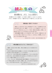
1
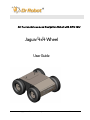
All-Terrain Autonomous Navigation Robot with GPS-IMU Jaguar 4x4 Wheel User Guide Copyright © 2014, Dr Robot Inc. All Rights Reserved. www.DrRobot.com V20.12.14 WARNINGS Do NOT power on the robot before reading and fully understanding the operation procedures explained in this manual. Always charge the battery when battery is running low or before storage. Always turn your robot off when not in use. Over-draining the battery (such as keeping the robot on without charging) will damage the battery. Never position your finger(s) in between the track and/or arm’s moving parts even when the power is off. The robot arms must be positioned to the rest position before turning on the robot. Neither the robot, nor the program is bug free, accident could happen; you have to make sure that the robot always maintains a safe distance from people during operation. Failure to follow these warnings could cause serious injury or death and/or damage to the robot. Copyright © 2014, Dr Robot Inc. All Rights Reserved. www.DrRobot.com V20.12.14 Copyright Statement This manual or any portion of it may not be copied or duplicated without the expressed written consent of Dr Robot. All the software, firmware, hardware and product design accompanying with Dr Robot’s product are solely owned and copyrighted by Dr Robot. End users are authorized to use for personal research and educational use only. Duplication, distribution, reverse-engineering, or commercial application of the Dr Robot or licensed software and hardware without the expressed written consent of Dr Robot is explicitly forbidden. www.DrRobot.com Contact General: [email protected] Technical Support: [email protected] 25 Valleywood Drive, Unit 20 Markham, Ontario, L3R 5L9, Canada Tel: (905) 943-9572 Fax: (905) 943-9197 Copyright © 2014, Dr Robot Inc. All Rights Reserved. www.DrRobot.com V20.12.14 Table of Contents I. II. III. IV. V. Specifications 5 Key Features 5 Jaguar Core Components 7 Main Upgrade Options 7 Knowing Your Robot 8 Overlook 8 Operation Scenario 9 Software Installation 9 Operation of Jaguar Robot 10 Turn on/off the Platform 10 Using Dr Robot Jaguar Control Program 10 Recharging 14 Using DrRobot Jaguar4X4 Motor Control Demo Program 15 Hardware and Electronics 16 Network Settings 16 Wireless Router Setting 16 Device Default Network Settings 17 Advanced Network Settings 17 Hardware Architecture 17 Motor Driver Board 19 Motion and Sensing Controller 19 Camera 19 GPS 19 9DOF IMU (Gyro, Accelerometer & Digital Compass) 19 Laser Scanner 20 Batteries 20 Charger 20 Powertrain (motor, speed-reducer and encoder) 20 Further Development & Programming 21 The Jaguar Control program 21 Motion Control/Sensing System 21 Laser Scanner 23 GPS 23 9 DOF IMU (Gyro/Accelerometer/Compass) 23 Camera with Two Way Audio 24 Advanced Development Copyright © 2014, Dr Robot Inc. All Rights Reserved. www.DrRobot.com -4- 24 V20.12.14 I. Specifications Jaguar-4x4-wheel Mobile Robotic Platform is designed for indoor and outdoor operation requiring higher ground clearance and faster maneuverability. Jaguar-4x4-wheel platform is a wheeled version of the Jaguar-Lite platform. Jaguar-4x4-wheel is driven by four powerful (80W) motors, one for each wheel. Jaguar-4x4-wheel platform is rugged, light weight (< 20Kg), fast (max 11km/hr), with high ground clearance (88mm), compact, weather and water resistant. It is designed for tough terrains and capable of running over vertical step up to 155mm and climbing up low rise stairs (up to 110mm step). Jaguar-4x4-wheel is fully wirelessly (802.11G) connected. It integrates outdoor GPS and 9 DOF IMU (Gyro/Accelerometer/Compass) for autonomous navigation. The integrated high resolution video/audio and laser scanner (optional) provide remote operator detail information of the surrounding. Besides the ready to use control and navigation software, a full development kit including SDK, data protocol and sample codes, is also available. Key Features Rugged and reliable mobile platform for indoor and outdoor applications with faster maneuverability (max 11Km/hr) and high ground clearance Indoor and outdoor operation requiring higher ground clearance and on tough terrains Weather and water resistant enclosure Climbing up > 45° slope and stairs (max 110mm or 4.5”) Light weight (< 20Kg) and compact design with large payload capacity Autonomous navigation with outdoor GPS and 9 DOF IMU (Gyro/Accelerometer/Compass) Managing max 155mm (6”) vertical step (obstacle) Surviving max 1200mm (4ft) drop to concrete Integrated Laser scanner (Optional) Integrated high resolution video camera with audio All 802.11G (optional 802.11N) wirelessly connected Head mounted display (optional) and Gamepad controller providing outdoor operation with large and clear view even under direct sunlight Ready to use control and navigation software Full development kit including SDK, data protocol and sample codes, supporting Microsoft® Robotics Studio, Microsoft® Visual Studio, NI LabVIEW®, MATLAB®, Java® Terrain: Sand, rock, concrete, gravel, grass, soil and others wet and dry Slope: > 45° Maximum vertical step: 155mm (6”) Stair climbing: Max stair step height 110mm (4.5”) Traverse: > 200mm (8”) Speed: 0 – 11Km/hr Turning radius: 0, min 750mm (29.5”) diameter of turning space Ground clearance: 88mm (3.5”) Operator remote control Autonomous navigation with GPS and 9 DOF IMU (Gyro/Accelerometer/Compass) Indoor vision landmark GPS (Optional) Sealed weather resistant enclosure Temperature: -30° to +50° Copyright © 2014, Dr Robot Inc. All Rights Reserved. www.DrRobot.com -5- V20.12.14 Shock resistant chassis Drop to concrete: Max: 1200mm (4ft) Rated: 900mm (3ft) Motion and sensing controller (PWM, Position and Speed Control) 5Hz GPS and 9 DOF IMU (Gyro/Accelerometer/Compass) Laser scanner (4m or 30m) (Optional) Temperature sensing & Voltage monitoring Headlights Color Camera (640x480, 30fps) with audio WiFi802.11G (Optional WiFi 802.11N) Ethernet (Optional) Ethernet (Optional) General purpose communication and power port (Optional) Gamepad controller Head mounted display (dual 640 x 480), equivalent to 60” display viewed in 2.7m (9 feet) (Optional) Portable computer (Optional) Rechargeable battery: LiPo 22.2V 10AH LiPo battery charger Nominal operation time: 2 hours (Optional 4 hours) Wheel Motors (24V): 4 units Max output (after gear down) (x4): Max 80W, 100Kg.cm/wheel Rated current: 2.75A, Max current: 16A Height: 265mm (10.5”) Width: 573mm (22.5”) Length: 615mm (24”) Weight: 20Kg (Standard Configuration) Carrying Payload (on flat surface): max 30Kg Dragging Payload (on flat surface): max 50Kg Full development kit including SDK, data protocol and sample codes, supporting Microsoft® Robotics Studio, Microsoft® Visual Studio, ROS, NI LabVIEW®, MATLAB® and Java® Copyright © 2014, Dr Robot Inc. All Rights Reserved. www.DrRobot.com -6- V20.12.14 Jaguar Core Components JAGUAR4x4W-ME Jaguar 4x4 Wheel Chassis (including motors and encoders) 1 PMS5005-J4W Motion and Sensing Controller (Jaguar 4x4 Wheel Version) 1 WFS802G WiFi 802.11b/g Wireless Module 1 DMD1200 12A (peak 25A) Dual-channel DC Motor Driver Module 2 PMCHR12 DC-DC Power Board 1 AXCAM-A 640x480 Networked Color Camera (max. 30fps) with Two-Way Audio 1 OGPS501 Outdoor GPS Receiver with 5Hz Update Rate and WAAS 1 IMU9000 9 DOF IMU (Gyro/Accelerometer/Compass) 1 WRT802G 802.11b/g wireless AP/router 1 BPN-LP-10 22.2 V 10 AH LiPo Battery Pack 1 LPBC5000 2A LiPo Battery Charger 1 GPC0010 Gamepad Controller 1 Main Upgrade Options Laser Scanner (Range 4m) for Indoor Application LAS04M Laser Scanner (Range 5.6m) for Indoor Application LAS04M Laser Scanner (Range 30m) for Outdoor Application LAS30M 22.2V 20 AH Li-Polymer Battery Pack Upgrade BPN-LP-20 Head Mounted Display (800x600) HMD8H6H 802.11N Wireless AP/Router WRT802N Host Controller PC HCPC1008 Please contact [email protected] for custom design and integration inquiry. Copyright © 2014, Dr Robot Inc. All Rights Reserved. www.DrRobot.com -7- V20.12.14 II. Knowing Your Robot Overlook The figure below illustrates the key components that you will identify on the Jaguar-4x4-Wheel robot. GPS Batteries Camera Headlights Power Switch Start Button Handle Bar Jaguar-4x4-Wheel Platform Copyright © 2014, Dr Robot Inc. All Rights Reserved. www.DrRobot.com -8- V20.12.14 Operation Scenario Diagram below illustrates the typical operation scenario. The Jaguar-4x4-wheel is a wireless networked outdoor mobile robot. It comes with a wireless 802.11 AP/router. The remote host controller PC running the “Jaguar Control” program connects to the Jaguar-4x4-wheel robot via: Network cable – Connect the robot on-board AP/router. (DO NOT connect to the WAN port), or Wireless – To connect the host controller PC to the on-robot wireless AP/router, configure the host PC’s wireless settings using the default wireless configuration settings found in the Network Connection session of this manual. Human operator carrying the host controller PC could use the head-mounted display (accessory option) and the included game-pad controller in outdoor environment to monitor and control the operator under any outdoor lighting environment, even under direct sunshine. The included “Jaguar Control” program will therefore be projected on the head-mounted display, where you could see all the sensor information from the robot, and the video streamed from the camera on robot (Please refer to “Jaguar Control program” session for detail). Head-mounted display (Optional) Gamepad Controller Portable PC (Host controller PC) (Optional) Typical Operation Scenario Note: The host controller PC running the “Jaguar Control” program could be mounted on the robot instead off the robot if your application requires so. Software Installation Jaguar Control programs, application development library and supporting documents could be found from the Jaguar software CD. On the host controller computer, you should install the following programs from the installation CD: “Jaguar Control” program - installed by the Setup.exe from CD Google Earth program - could be downloaded from http://earth.google.com/downloadearth.html. Please follow its installation instruction. Copyright © 2014, Dr Robot Inc. All Rights Reserved. www.DrRobot.com -9- V20.12.14 III. Operation of Jaguar Robot End user could develop his own Jaguar control program using the supplied development API and tools. Here, we will show you how to control the robot using the included “Jaguar Control Program” (You need to install Google Earth program first). Turn on/off the Platform Please follow the below steps to turn on the robot. 1. Turn the main switch to "ON" position. 2. Press the start button for a while (around 1 second) then release. If you see the green LED on the start button is on, the system is powered up. If not, please check the battery to make sure it is fully charged. Turn the main switch to "OFF" position, the system will shut down. Using Dr Robot Jaguar Control Program This program will demonstrate how to control and navigate the Jaguar-4x4-wheel, and how to interpret, process, display and log multi-sensor information. This program is provided with source code (c#). updates motor encoder reading, motor temperature, board voltage and battery voltage measured at 10Hz; reads and displays IMU and Laser Range sensor data; displays GPS readings on the Google Earth; displays and controls Axis camera. Once you start this program, you will see a “Login Window” It will read all the configuration information from “outdoorrobotconfig.xml” under c:\DrRobotAppFile\. When “Connect Robot” is clicked, it will start the WiRobotGateway program (also under c:\DrRobotAppFile\) and will try connecting to the Robot. Copyright © 2014, Dr Robot Inc. All Rights Reserved. www.DrRobot.com - 10 - V20.12.14 Google Earth is then loaded (this may take a while). Google Earth supports offline use (without Internet), but you have to obtain the map online ahead of use. When Internet is not presented, this loading process will take a longer time when trying to connect with Google Earth website. You will not get the correct Latitude and Longitude position by clicking on map before the map loading is finished. When loaded, click “OK” button. “FlyToSetPoint” button will bring you to the location (latitude/longitude) specified in “outdoorrobotconfig.xml”. This is the location you would like the map to center and show around. You should modify this location according to your location. This could be done by inputting the value in this xml file or navigating on Google Earth map to your interested point, then clicking “SaveSetPoint” button. The location value of the map center will then be saved to the “outdoorrobotconfig.xml” when program is closed. Copyright © 2014, Dr Robot Inc. All Rights Reserved. www.DrRobot.com - 11 - V20.12.14 You could use the vertical track bar to zoom in or out. When the GPS-IMU module is presented, this program will connect and display the GPS information on Google Earth and IMU raw data on the 6 chart boxes. When camera is presented, the video and AV control buttons will be shown in the video window. You could use the included Gamepad controller to navigate the robot. When used outdoor, especially under direct sun lights, head-mounted display (optional accessory) will provide clear and large display with excellent outdoor experience. Camera display to full size Minimize camera display to original size Headlight On/OFF Wheel Forward / Backward Control Wheel Turning Control Gamepad Control Note: when using Gamepad control, you need to make sure the program window is in “focus”. Copyright © 2014, Dr Robot Inc. All Rights Reserved. www.DrRobot.com - 12 - V20.12.14 When is clicked, it will display laser scanner data in polar view as shown below. Yellow: Driving Direction (Modified by sensor map) Blue: Gamepad Driving Direction Polar Sensor Map Enable Collision Avoidance * When the "CA" checkbox is checked, the program will limit the maximum output PWM to 65% full power. Battery information and motor information is displayed here. If the robot uses the included Li-Po battery, you need to stop the robot when voltage is below marked voltage (22.2V) in order to prevent battery damage. Motor temperatures are also displayed here. “Encoder Pos” boxes show the encoder position values received in motor driver board from motion control board. When selected, the motors will be disabled when measured motor temperature is higher than the safety threshold (we recommend this feature is enabled for normal operation); When de-selected, this motor over-heat protection feature is disabled. The two horizontal track bars show the Gamepad controller’s left and right stick control value. You could record raw GPS-IMU/Encoder sensor data using saved to "c:\DrRoboAppFile" folder with file name GPSIMURec*.txt. button. The raw sensor data file will be All traces are displayed on Google Earth by KML data. Since the current version of Google Earth does not provide programming method to clear these KML data, there is risk of memory leak. You could manually clear these KML Copyright © 2014, Dr Robot Inc. All Rights Reserved. www.DrRobot.com - 13 - V20.12.14 data by right-clicking on “Temporary Places”, then choosing “Delete Contents”. (That is why we did not hide Google Earth program) On normal program exit, Google Earth will be closed. However, you should double check using “Windows Task Manager”; otherwise, you may not be able to display Google Earth when you start Jaguar control program again. Recharging Jaguar robot uses high performance LiPo batteries. Extreme caution is needed when dealing with this type of battery, explosion and damage could occur. Please read the Charge Station manual first and follow all the safety rules before proceeding further. 1) Turn off the robot 2) Loose the screws of Battery Box, disconnect the 2-Pin Tamiya connector and take the Battery Box out. to make sure "LiPo BALANCE" is displayed on the LCD screen. If not, 3) Power on the Charge Station. Use use "Type/Stop" button to change battery type to "LiPo Battery" and press to set charging mode to “LiPo BALANCE” . 4) You can use + / + buttons to change the charge current, DO NOT exceed the 2A charging current and do not modify the battery voltage. It should be "22.2V (6S)" for Jaguar robot. 5) Connect the charging 7-Pin, 3-Pin & 2-Pin connectors to charger as below images. Copyright © 2014, Dr Robot Inc. All Rights Reserved. www.DrRobot.com - 14 - V20.12.14 6) Press button for few seconds, the charge station will check the battery and display what the reading is. It should be same as your settings above. 7) If everything is right, you can press button again to start charging. to switch the display to show the battery status. The display 8) Press should show each battery reading as below image. * Note: If any battery reading is missing, please turn off the charging station and turn the Power switch to “OFF”, and check the 7-pin connector, make sure it is connect well. 9) Keep the charger away from children and pet at all time! Never leave the charger unsupervised when it is connected to its power supply. For more detail about charger station operation, warning and error message, maintenance and safety message, please refer to “Intelligent Digital Balance Charger Operating Manual”. Using DrRobot Jaguar4X4 Motor Control Demo Program You could install the Jaguar4X4 Motor Control demo program from the CD. After installation, you could run the WiRobotGateway program from Desktop. Please input the Robot ID as “DrRobot”. Make sure the IP address is your robot IP (default is “192.168.0.60”) and the port number is “10001”. Click the “Connect” button. Then run the DrRobot Jaguar4X4 Motor Control Demo program. Copyright © 2014, Dr Robot Inc. All Rights Reserved. www.DrRobot.com - 15 - V20.12.14 In this program, you could use open loop PWM control(by clicking “PWM Control Go” button), velocity Control(by clicking “Velocity Control Go” button) and position control (by clicking “Distance Control Go” button). You also could adjust the default velocity control PID and position control PID parameters. All default value are displayed on the program GUI. IV. Hardware and Electronics Network Settings Wireless Router Setting The included pre-configured wireless 802.11 B/G router has the following pre-set settings: SSID DriJaguar Router LAN 192.168.0.245 WEP 128bits Login ID admin KEY drrobotdrrobot Password drrobot Key Type Open Key Copyright © 2014, Dr Robot Inc. All Rights Reserved. www.DrRobot.com - 16 - V20.12.14 Device Default Network Settings Note: The Ethernet modules are configured to serial-to-Ethernet mode in Jaguar platform. Ethernet Module 1 192.168.0.60 Port 1 Port Number 10001, UDP 115200. 8, N, 1, no flow control Port 2 Port Number 10002, TCP 19200. 8, N, 1, no flow control Ethernet Module 2 192.168.0.61 Port 1 Port Number 10001, TCP 57600. 8, N, 1, no flow control Port 2 Port Number 10002, TCP 115200. 8, N, 1, no flow control Camera 192.168.0.65 User ID Root Password drrobot Port 8081 Advanced Network Settings You could also change the Wireless AP/router settings such as IP and SSID etc., if you need to do so, you are required to change the network settings on the Ethernet modules on the robot by following the guidelines as illustrated on the Ethernet Module manual. Please contact [email protected] if you need further support. Hardware Architecture The diagram below illustrates the inter-connection between the core electronic circuits and modules (some are optional accessories). Copyright © 2014, Dr Robot Inc. All Rights Reserved. www.DrRobot.com - 17 - V20.12.14 Charging Plug Antenna Right Front Motor Right Rear Motor LiPo 22.2V 10AH Left Front Motor Left Rear Motor OFF Host Control PC ON Main Switch Motor Driver Board #1 Motor Driver Board #1 Gamepad Controller 5V Head Lights 9 DOF IMU (Gyro/ Accelerometer/Compass) Power 5V GPS Module Power 5V 3.3V Camera (AV) Power 5V = Copyright © 2014, Dr Robot Inc. All Rights Reserved. www.DrRobot.com - 18 - V20.12.14 Antenna 5V Power 5V Wireless AP/Router Power 5V LAN 5V Ethernet Module 2 Power 3.3V Port 10002 Port 10001 DC-DC Power Board Laser Scanner Ethernet Module 1 Power 3.3V Port 10002 Port 10001 Motion Sensing Controller (Jaguar Ver.) Communication Temperature Encoder-D PWM-D PWM-B Encoder-C Encoder-B PWM-C PWM-A Power 5V Encoder-A Voltage Meter Head Light Control Power Control Port IN Head Mount Display Motor Driver Board The left front and left rear motors are connected to the 1st channel on the motor driver board while the right front and right rear motors are connected to the 2nd channel. Input power Max current Input voltage H-Bridge 2 channels up to 25A continuous power per channel, peak up to 50A per channel for a few seconds 6~24V, 30V absolute max Motion and Sensing Controller This is a special version of PMS5005 board. Input power 5V 6 PWM output Motor control mode Channel 3, 4 for left and right wheels PWM control; Velocity control; Position control Sensor sampling Encoders: Channel 1,2 for left and right rear wheel Channel 3,4 for left and right front wheel Board voltage measuring Battery voltage measuring Motor temperature measuring (4 units) Other extended A/D channels (please contact Dr Robot). Camera Input power Lens Light sensitivity 5V 4.4mm: 47° horizontal view, F2.0, fixed iris, fixed focus 1-10000 lux, F2.0 0 lux with headlights LED on 640x480 to 160x120 H.264: 30 fps in all resolutions Motion JPEG: 30 fps in all resolutions MPEG-4 Part 2: 30 fps in all resolutions Resolutions Frame rate Video compression H.264 (MPEG-4 Part 10/AVC), Motion JPEG MPEG-4 Part 2 (ISO/IEC 14496-2) Audio streaming Other features Two-way PIR motion sensor with configurable sensitivity. Max range: 6 m GPS Input power Update rate Sensitivity Accuracy 5V 5Hz - 185dBW minimum Standard GPS service: WAAS service: Output Interface Position: <= 15m 95% typical Velocity: 0.1knot RMS steady state Position: <= 3m 95% typical NMEA 0183, default GPRMC/GPGGA/GPGSA/GPVTG Binary Output 9DOF IMU (Gyro, Accelerometer & Digital Compass) Input power 5V Copyright © 2014, Dr Robot Inc. All Rights Reserved. www.DrRobot.com - 19 - V20.12.14 Gyro Sensors ITG3200 Triple-Axis digital output gyro sensor Accelerometers 3 Axis ADXL345 13bit resolution Max +/-16G 3 Axis HMC5883L magnetometer 50Hz Output all sensors raw AD data, magnetic sensor will be measured every 220ms Magnetic Compass Output Frequency Laser Scanner Two laser scanner options are available, one with measurement range of 0.02-4m, and other one is 0.1-30m. Input power Detectable range Accuracy Measurement Resolution Angular Resolution Scanning angle 5V 0.02-4m 0.02 to 1m: +/- 10mm 1 to 4m: 1% 1mm approx 0.36 o (360 o/1024 partition) 240 o Input power Detectable range Accuracy Measurement Resolution Angular Resolution Scanning angle 12 V 0.1-30m 0.1 to 10m: +/- 30mm 1mm approx 0.25 o (360o/1440 steps) 270 o Batteries Battery type Rated Voltage Capacity Discharge rate Max charge rate Cycle life Li-Po 22.2V (6 cells, 3.7V/cell) 10Ah Max 50A continuous, Max 100A peak 10A 500-1000 times Charger Charger type Maximum charge current Maximum discharge current Power Input LiPo Charger 2A 2A 100-240V Powertrain (motor, speed-reducer and encoder) The following specifications are defined at the output shaft after speed-reduction. Drive wheel shafts Track-wheel motors (4 units) Motor rated voltage Motor rated current Motor max current Shaft rated speed Shaft rated torque Shaft encoder resolution DC motors with steel gearbox 24V 2.75A 16A 230RPM 13.5 Kg.cm 150 counts per revolution Copyright © 2014, Dr Robot Inc. All Rights Reserved. www.DrRobot.com - 20 - V20.12.14 V. Further Development & Programming The Jaguar Control program The Jaguar Control program is written with Visual Studio 2008 express (in C#) under .Net 3.5 framework. You could download the development tools (Visual Studio 2008 express under .Net 3.5 framework) free from Microsoft. Please refer to the “Dr Robot Application Development Notes on C# Programming for Robot Control” for further information. The control program uses the supporting components and libraries that should have been installed when you install the control program from the installation CD: 1. DRROBOTSentinelCONTROL.OCX: Please refer to “WiRobot SDK API Reference Manual.pdf” for detail. 2. WiRobotGateway.exe 3. AXIS Media Control Library Set These are the camera control component for the AXIS Mini Camera (P/N: AXCAM) used for Jaguar robot. Please refer to “AXIS Media Control SDK Help” for detail. Motion Control/Sensing System Jaguar-4x4-Wheel comes with a special version of PMS5005 as its motion control and sensing board. It follows the Dr Robot WiRobotSDK protocol. User could control and access Jaguar by Dr Robot ActiveX control (DrRobotSentinelActivexControl.ocx) and WiRobot gateway program. Based on the protocol, you could develop your own program for any operation system. You could request protocol sample code from Dr Robot using C++/Java. You should also contact Dr Robot with any questions regarding SDK API and protocol. The communication port is connected at Ethernet module-I port 1. Gateway program will connect to this board at 192.168.0.60, port 10001. Here is C# sample code to control Jaguar-4x4-Wheel System with ActiveX control, myJaguar is DrRobotSentinelActiveXControl. Wheel Motor control: private void myJaguar_MotorSensorEvent(object sender, EventArgs e) { leftRearWheelMotor.encoderDir = myJaguar.GetEncoderDir1(); leftRearWheelMotor.encoderPos = myJaguar.GetEncoderPulse1(); leftRearWheelMotor.encodeSpeed = myJaguar.GetEncoderSpeed1(); rightRearWheelMotor.encoderDir = myJaguar.GetEncoderDir2(); rightRearWheelMotor.encoderPos = myJaguar.GetEncoderPulse2(); rightRearWheelMotor.encodeSpeed = myJaguar.GetEncoderSpeed2(); WheelMotor.output leftFrontWheelMotor.outputPWM = myJaguar.GetMotorPWMValue4(); rightFrontWheelMotor.outputPWM = myJaguar.GetMotorPWMvalue5(); leftRearWheelMotor.outputPWM = myJaguar.GetMotorPWMValue1(); rightRearWheelMotor.outputPWM = myJaguar.GetMotorPWMValue2(); } Copyright © 2014, Dr Robot Inc. All Rights Reserved. www.DrRobot.com - 21 - V20.12.14 You could read board voltage(5V) and battery voltage in standard sensor Event. private void myJaguar_StandardSensorEvent(object sender, EventArgs e) { boardVol = ((double) myJaguar.GetSensorBatteryAD1() / 4095 * 9); motVol = ((double) myJaguar.GetSensorBatteryAD2() / 4095 * 34.498); } You could read motor temperature sensor in custom sensor event, function Trans2Temperature() is based on the sensor specification to translate AD value to temperature (in celcius degree). Also you could read left/right wheel motor encoder in this event. private void myJaguar_CustomSensorEvent(object sender, EventArgs e) { // front left track motor double tempM = Trans2Temperature((double)myJaguar.GetCustomAD5()); tempM = double.Parse(tempM.ToString("0.00")); lblTemp1.Text = tempM.ToString("0.00"); // front right track motor tempM = Trans2Temperature((double)myJaguar.GetCustomAD6()); tempM = double.Parse(tempM.ToString("0.00")); lblTemp2.Text = tempM.ToString("0.00"); // rear left track motor tempM = Trans2Temperature((double)myJaguar.GetCustomAD7()); tempM = double.Parse(tempM.ToString("0.00")); lblTemp3.Text = tempM.ToString("0.00"); // rear right track motor tempM = Trans2Temperature((double)myJaguar.GetCustomAD8()); tempM = double.Parse(tempM.ToString("0.00")); lblTemp4.Text = tempM.ToString("0.00"); leftFrontWheelMotor.encoderPos = myJaguar.GetEncoderPulse4(); leftFrontWheelMotor.encodeSpeed = myJaguar.GetEncoderSpeed4(); leftFrontWheelMotor.encoderDir = myJaguar.GetEncoderDir4(); rightFrontWheelMotor.encoderPos = myJaguar.GetEncoderPulse5(); rightFrontWheelMotor.encodeSpeed = myJaguar.GetEncoderSpeed5(); rightFrontWheelMotor.encoderDir = myJaguar.GetEncoderDir5(); } To stop all motor, you could use: myJaguar.DcMotorPwmNonTimeCtrAll(16384, 16384, 16384, 16384, 16384, 16384); For track/wheel motor control, we use independ-drive mode. Under this mode, PWM channel 3 is driving Left front wheel motor, PWM channel 4 is driving right front motor, PWM channel 0 is driving left rear motor and PWM channel 1 is driving right front mtoor. To move forward with full power myJaguar.DcMotorPwmNonTimeCtrAll(32767,0,NOCONTROL,32767,0,NOCONTROL); To move backward with full power myJaguar.DcMotorPwmNonTimeCtrAll(0,32767,NOCONTROL,0,32767,NOCONTROL); Copyright © 2014, Dr Robot Inc. All Rights Reserved. www.DrRobot.com - 22 - V20.12.14 To turn left with full power myJaguar.DcMotorPwmNonTimeCtrAll(0,0,NOCONTROL,0,0,NOCONTROL); To turn right with full power myJaguar.DcMotorPwmNonTimeCtrAll(32767,32767,NOCONTROL,32767,32767,NOCO NTROL); For encoder speed/position control of each motor, you could referee “DrRobot Jaguar4X4 Motor Control Demo” program and you could find the source code in the installation folder. To control head lights, using expanded IO port bit7. Turn off light: Turn on light: myJaguar.SetCustomDOUT(expandedIO & 0x7f); myJaguar.SetCustomDOUT(expandedIO | 0x80); Software watchdog: The system will automatically, stop all the motors if it does not received any data package in 5 seconds. Laser Scanner Laser Ranger sensor (4m version, URG-04LX) is connected to Ethernet module–1 port 2 after voltage level conversion. You could access the sensor data via TCP socket at port 10002 with IP 192.168.0.60. Default settings for the serial port are: 115200, 8, N, 1, no flow control, TCP, port number 10002 Date and communication protocol could be found in “URG-04LX commspec_eg.pdf”. GPS GPS sensor output interface is RS232 serial port, and connected to Ethernet module-2 port 2 after voltage level conversion. You could access the sensor data via TCP socket at port 10002 with IP 192.168.0.61. Default settings for the serial port are: 115200, 8, N, 1, no flow control, TCP, port number 10002 NMEA 0183 sentence is described in file “GPS18x_TechnicalSpecifications.pdf”. GPS configuration tool is SNSRXCFG_200.exe 9 DOF IMU (Gyro/Accelerometer/Compass) The output interface for this IMU sensor module is serial port. It is connected to Ethernet module-2 port 1. You could read from this sensor via TCP port 10001 at IP 192.168.0.61. Serial Port Settings: 57600, 8, N, 1, no flow control, TCP, port number 10001. The sensor output rate is 50Hz (20ms) with output format of ASICII. It’s easier to read with a terminal program since the sensors’ measurements are reported in ASCII. All measurements are delimited with “,”characters as well as a carriage return and line feed at the end of the data frame. Format: “$seq,accelX,accleY,accelZ,,gyroX,gyroY,gyroZ,magnetomX, magnetomY, magnetomZ#” "seq" is data package sequency number, value is in range: 0 ~255. After “seq”, the data are raw AD value for each sensor. Sample data string: “$2,9,1,255,20,40,3,235,4000,20#” Please note the magnetic sensor will be measured every 220ms, so if the output value is 0, means no new magnetic sensor data in this data package. Copyright © 2014, Dr Robot Inc. All Rights Reserved. www.DrRobot.com - 23 - V20.12.14 Camera with Two Way Audio You need to install the camera ActiveX control on your system by running the “AXISMediaControlSDK.exe”. You could find some sample codes (C++, C#, VB) in C:\Program Files\Axis Communications\AXIS Media Control SDK\samples and the corresponding SDK documents in C:\Program Files\Axis Communications\AXIS Media Control SDK\doc. By using the Microsoft’s “Windows Media Encoder 9” and Axis video capture driver, you could also access this camera in Intel’s OpenCV as same as accessing a USB camera. Advanced Development Please refer to document “GPS-IMU Sensor Module and Outdoor Autonomous Navigation Program” for detail on autonomous navigation programming using the Jaguar GPS and IMU system module. Support and sample codes are available for using OpenCV, LabVIEW and MATLAB. Please contact [email protected] for further information. Copyright © 2014, Dr Robot Inc. All Rights Reserved. www.DrRobot.com - 24 - V20.12.14