1
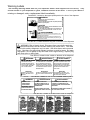
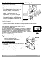
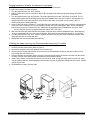
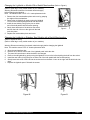
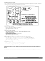
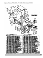
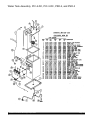
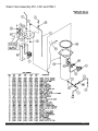
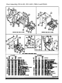
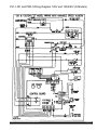
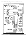
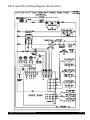
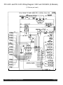
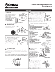
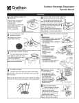
Crathco Powdered Beverage Dispensers
Operation and Instruction Manual
for
PIC (1, 2, & 3) DC,
PSD (1, 2, & 3) DC & PIC-33A Series
TABLE OF CONTENTS
Warning Labels......................................2
Installation.........................................3
Start up Procedures................................3-4
Hot Chocolate
How To Dispense Cappuccino.............4
Adjustments.......................................5-7
Service and Cleaning.........................7-11
Troubleshooting.................................12-13
PIC-33A
Exploded Views...............................14-21
Wiring Diagram....................................22-26
Prior authorization must be obtained
from Grindmaster Crathco Systems for
all warranty claims.
PIC-1-DC
PIC-2-DC
Grindmaster Crathco Systems, Inc.
4003 Collins Lane
Louisville, Kentucky 40245
(502) 425-4776 800-695-4500
(800) 568-5715 (technical service only)
FAX (502) 425-4664
www.grindmaster.com
Grindmaster Crathco Systems, Inc., 1996
Printed in the USA
0900 Form # CC-302-12
Part # 61146
Warning Labels
The following warning labels were on your dispenser when it was shipped from the factory. They
should remain on your dispenser in good, readable condition at all times. If one of your labels is
missing or damaged, order a replacement label immediately.
Part #62337, Located on the upper splash panel on the front of the dispenser
WARNING
Contents can cause severe burns if
handled improperly.
Cup must rest flat on tray with 1/4” (6mm) clearance
between cup and spout.
AVISO
EL CONTENIDO PUEDE CAUSAR QUEMADURAS SI SE
USA INCORRECTAMENTE.
LA TAZA DEBE ESTAR DERECHA EN LA BANDEJA CON
6MM (1/4”) DE DISTANCIA ENTRE LA TAZA Y EL TUBO
PLASTICO.
AVERTISSEMENT
Contenu peut provoquer des brulures graves si il est
manipule incorrectement.
Le gobelet doit etre place a plat sur le plateau tout en
maintenant un espace libre de 6mm (1/4”) entre le gobelet et le bec verseur.
Part #61321, Located behind the drip pan on the front of the dispenser
! WARNING: Risk of electric shock. Disconnect from power before servicing.
Hot parts and surfaces inside and outside machine may cause burns. Tank drain
hose inside machine dispenses very hot water. Will cause burns and/or personal
injury. Must have five gallon heat resistant container to catch hot water. Hot water
may splash. Do not attempt to stop hot water once it begins flowing. Replace plug
and clamp prior to refilling tank.
Part #61319, Located on the outside on the back of the dispenser
WARNING:
ADVERTENCIA:
ADVERTISSEMENT:
RISK OF ELECTRIC SHOCK.
DISCONNECT FROM
POWER BEFORE SERVICING. HOT PARTS AND SURFACES INSIDE MACHINE
MAY CAUSE BURNS.
RIESGO DE CHOQUE ELECTRICO. DESCONECTE LA MAQUINA
DE LA CORRIENTE ANTES DE
ARREGLARA. PIEZAS Y SUPERFICES CALIENTES DENTROS DE
LA MAQUINA PUEDEN CAUSAR
QUEMADURAS.
IMPORTANT
CONNECT TO A WATER
SUPPLY BEFORE PLUGGING IN.
IMPORTANTE
IMPORTANT
CONECTE LA MAQUINA A UNA VIA RACCORDER L’APPAREIL A LA
DE AGUA ANTES DE ENCHUFAR- DISTRIBUTION D’EAU AVANT DE
LA.
METTRE SOUS TENSION.
DANGER DE CHOC ELECTRIQUE.
METTRE L’APPAREIL HORS TENSION AVANT DE L’ENTRETENIR.
DES ELEMENTS ET SURFACES
CHAUDS PEUVENT PROVOQUER
DES BRULURES. MANIPULER
AVEC SOIN.
Part #61326, Located on the outside on the left of the dispenser
WARNING:
HOT PARTS AND
SURFACES MAY
CAUSE BURNS.
ADVERTENCIA:
PIEZAS Y SUPERFICES
CALIENTES DENTRO DE LA
MAQUINA PUEDEN CAUSAR
QUEMADURAS.
ADJUSTMENT INSTRUCTION ON THE BACK OF INSTRUCCIONES DE AJUSTE
THE ACCESS PANEL.
DENTRO DEL PANEL DE ACCESO.
ADVERTISSEMENT:
DES ELEMENTS ET SURFACES
CHAUDS A L’INTERIEUR DE L’APPAREIL PEUVENT PROVOQUER DES
BRULURES.
CONSIGNES DE REGLAGE AU VERSO
DE LA PLAQUE D’ACCES.
Part #61325, Located on the drain hose inside the dispenser
Crathco Powdered Beverage Dispensers
Page 2
Installation
Water Inlet Connection:
The National Sanitation Foundation requires the following for an NSF approved water hook-up:
1. A quick disconnect water connection or enough coiled tubing so that the machine can be moved for cleaning
underneath.
2. An approved backflow prevention device, such as a double check valve to be installed between the machine and
water supply. A 1/4" male flare adapter is provided (packed inside drain tray) to be attached by installer to the
back of the machine for hook-up to water supply. On units plumbed to permanent water line, installation of a water
filter/softener system is recommended to prevent lime and scale build up in the machine. On units pumping from a
remote water container, filtered water is recommended to prevent lime and scale buildup in the machine.
3. Water pipe connections and fixtures directly connected to potable water supply shall be sized, installed, and
maintained in accordance with Federal, State, and Local codes.
Start-up Procedure for Standard Units:
(Refer to serial tag to verify model number of your machine)
1. Install drain tray in front of machine. Connect the 1/4" male flare fitting (packed in drain tray) to the inlet valve on the
back of the machine.
2. Flush the water line to purge any debris from the supply line.
3. Connect a 1/4" water line to the 1/4" male flare connection and turn the water supply on.
Minimum water pressure to the machine: 20 psi
Maximum water pressure to the machine: 120 psi
4. Plug the power cord into a proper electrical outlet.
5. Turn the power switch to the “ON” position and allow the water tank to fill. The machine will make a subtle hissing
sound when this occurs. Allow 3-4 minutes for fill time depending on inlet water pressure.
6. After the water tank has filled, allow 30-45 minutes for the water to reach operating temperature depending on
wattage and tank size. (Green ready light will illuminate when tank is up to preset temperature).
7. Remove the powder hoppers and fill with desired powder product. IMPORTANT: Check to make sure that the auger
inside the hopper is correctly installed prior to filling (see figure F on page 8 for auger installation). Reinstall powder
hoppers. Make sure hopper elbows are down.
8. Peel protective film off photo merchandiser cover.
Note: If water supply is allowed to run dry, watchdog timer circuit may disable fill circuit. Ensure adequate
water supply for machine then reset machine by turning power switch off 1 second then ON.
Crathco Powdered Beverage Dispensers
Page 3
Start-Up Procedures for Pump Units (PIC 2-DC & PIC 3-DC only):
(Refer to serial tag to verify model number of your machine)
Note: Pump units are not designed to be plumbed to pressurized water source.
1. Place a full 5 gallon water container within 3 feet vertically and 2 feet horizontally of the machine.
2. Drop the hose at the rear of the machine into the water container (The hose should extend to approximately 1 inch
from the bottom of the water container).
Note: Do not let the end of the hose touch the bottom of the container. Shorten the hose if necessary.
If you need a longer hose, remove the back access panel, unclamp existing hose, replace with longer hose a n d
replace clamp.
3. Plug the power cord into a proper electrical outlet.
4. Turn the power switch to the “ON” position and allow the water tank to fill. The machine will make a sound
when this occurs. Allow 3-4 minutes for fill time.
5. After the water tank has filled, allow 30-45 minutes for the water to reach operating temperature (Green ready light
will illuminate when tank is up to preset temperature).
6. Remove the powder hoppers and fill with desired powder product. IMPORTANT: Check to make sure that the auger
inside the hopper is correctly installed prior to filling. Reinstall powder hoppers.
7. Peel protective film off photo merchandiser cover.
How to Dispense a Cup of Cappuccino
On models with manual dispense switches:
(Refer to serial tag to verify model number of your machine)
1. Place a cup under the selected drink dispense nozzle.
2. Push and hold dispense switch until cup is 2/3 full and then release switch.
On models starting with PIC-1ADC, PIC-2ADC and PIC-3ADC with portion control dispense
switches:
(Refer to serial tag to verify model number of your machine)
1. Place a cup under the selected drink dispense nozzle.
2. Push button for one second, then release to dispense one serving.
Note: Portion may be cancelled by push and release of the switch.
Note: Cup must rest flat on tray with 1/4” (6 mm) clearance between cup and spout. Contents can cause
severe burns if handled improperly.
Crathco Powdered Beverage Dispensers
Page 4
Adjustments
Portion Adjustment
(On models starting with PIC-2A-DC and PIC-3A-DC with portion control dispense switches)
1.
2.
3.
4.
Place a cup under the selected drink dispense nozzle.
Press and hold the dispense switch.
After a 10 second time delay, the machine is triggered into program mode and will begin dispensing.
Continue pressing the button until cup is approximately 2/3 full, then release the switch to prevent overfill. The
elapsed portion dispense time is saved to memory and will remain until the dispense switch is
reprogrammed.
5. Check the portion size by placing an empty cup under the desired dispense nozzle, then press and release
the dispense switch. The machine will dispense the preprogrammed portion size.
6. If the portion size is incorrect, repeat steps 1, 2, 3, 4 & 5 until the desired portion size is achieved.
(On models starting with PIC-33A with 3 portion sizes per head.)
1. Place a cup under the selected drink dispense nozzle.
2. Press and hold the S, M, or L button on the touch pad.
(Hold button throughout entire procedure.)
The programming mode will not be activated until you:
3. Press and release the Manual (top-off) button.
After releasing the Manual (top-off) button, the 10-second delay is activated.
4. After 10 seconds, product will begin to dispense.
5. Release the S, M, or L button when cup is approximately 2/3 full.
6. Check the portion size by placing an empty cup under the desired dispense nozzle, then press and release
the dispense switch. The machine will dispense the preprogrammed portion size.
7. If the portion size is incorrect, repeat steps 1, 2, 3, 4 & 5 until the desired portion size is achieved.
Three buttons per head are capable of being programmed.
Thermostat Adjustment (Refer to Figure A)
Note: The thermostat range is approximately 160 to 200 degrees Fahrenheit. The tank temperature is factory
set at approximately 180°F, making beverage temperature slightly lower than 180 degrees Fahrenheit.
Tool required: #2 Phillips screwdriver.
1. Unplug machine.
2. Remove the drip pan.
3. Remove the upper splash panel on the front of the machine
by removing the four Phillips head screws.
4. Locate the thermostat adjustment dial on the left side of the
control board. (Refer to Figure A)
5. To adjust the temperature of the water being dispensed, turn
the adjustment dial on the control board.
(Turn clockwise to increase the water temperature or counter
clockwise to decrease the water temperature)
!
CAUTION! Do not force the adjustment dial beyond its 270 degrees of rotation
or damage to the control board may occur.
Crathco Powdered Beverage Dispensers
Page 5
Drink Strength Adjustment (Refer to Figure A)
Tools Required: #2 Phillips Screwdriver
Warning: Risk of Electric Shock! Always turn
off power to machine while servicing or
making internal adjustments to machine.
1. Dispense a drink to determine if drink is too
strong or too weak.
2. Turn off power to machine at power switch.
3. Remove upper front splash cover below
dispense heads in front of machine.
4. Using a flat head screwdriver, adjust individual
dispense heads by rotating appropriate
adjustment knob. Turn on power to machine and
dispense a drink to determine if drink strength is
acceptable. If drink is not acceptable, turn off power
to machine and repeat adjustment steps until
desired drink strength is achieved. Note: Clockwise
rotation will result in a stronger drink and
counterclockwise will result in a weaker drink.
Note: Water flow rate is factory preset at
approximately 0.80 ounces per second.
Figure A
Crathco Powdered Beverage Dispensers
Page 6
Portion Size & Drink Strength Adjustment for Model PIC-J (Refer to Figure B)
Tool required: #2 Flat Head screwdriver.
1. Dispense a drink to determine if drink is too strong,
weak or if portion size is correct.
2. Turn off power to machine at power switch.
3. Drink strength and portion size controls will be
found behind the drain tray. (Refer to Figure B) For
portion size adjustment, turn dial clockwise to
increase dispense volume. To decrease volume
turn dial counterclockwise. For drink strength
adjustment turn dial clockwise to increase drink
strength. To decrease strength turn dial
counterclockwise. Turn on power to machine and
dispense a drink to determine if drink strength or
portion is acceptable. If drink strength or portion is
not acceptable, turn off power to machine and
repeat adjustment steps until desired drink strength
or portion is achieved. Note: clockwise rotation will
result in a stronger drink and counterclockwise will
result in a weaker drink.
Note: Water flow rate is factory preset at approximately
0.80 ounces per second.
PORTION SIZE ADJUSTMENT
TURN DIAL CLOCKWISE TO
INCREASE DISPENSE VOLUME
COUNTERCLOCKWISE TO
DECREASE DISPENSE VOLUME
DRINK STRENGTH ADJUST MENT
TURN DIAL CLOCKWISE TO
INCREASE DRINK STRENGTH
COUNTERCLOCKWISE TO
DECREASE STRENGTH
Figure B
* To adjust flow rate, remove left side upper panel. Use flat head screwdriver and turn knob on respective
dump valve. WARNING: Do not adjust flow rate above the factory setting to prevent funnel overflow.
Using the Ambient Temperature Option (Refer to Figure C)
(On models equipped with this option)
The Ambient Temperature Option is only available on the left head of the machine.To
dispense ambient temperature product from the left head, flip the “hot/cold” switch
(behind the unit’s door and below the left hopper) in the “cold” position. To dispense
hot product from the left head, the “hot/cold” switch should be in the “hot” position.
Note: Water flow rate is factory set at approximately 0.80 oz per second. Do not adjust
flow rate above the factory setting to prevent funnel overflow.
Service and Cleaning
!
Figure C
Caution: When cleaning this unit, do not use cleansers,
liquid bleach, powders or any other substance that
contains chlorine. These products promote corrosion
of stainless steel and plastics parts.
Use of these products will void the warranty.
Daily Cleaning and Maintenance
1. Empty the drip pan as needed and wash daily in a solution of
dish detergent.
2. Rinse out the whipper chambers by placing the rinse switch
(located on the right of the dispensing valves when the door is
open) in the "ON" position. Dispense one to two cups until the water
is clean. Short bursts of dispensing may also help clean the chambers.
When completed, return the rinse switch to the "OFF" position.
3. Remove the hoppers and refill with product.
Crathco Powdered Beverage Dispensers
Figure D
Page 7
Weekly Cleaning
Removing and Cleaning the Chambers (Refer to Figure D)
1. Open the door and remove the mixing funnel shroud by pulling forward while turning 1/4 turn to the right.
Lift off and remove.
2. Remove the mixing funnel by lifting the neck of the funnel out of the whipper chamber, then tilt to the left.
With one hand on the water inlet fitting on the back panel, pull the funnel out of the white ring.
3. Remove the whipper chamber by rotating it 1/8 of a turn to the right, then pull to remove.
4. Remove the whipper blade by grasping the whipper blade with two fingers and firmly pulling to remove.
5. All parts in contact with food must be washed, rinsed, sanitized and air dried.
To Reassemble
1. Replace the whipper blade by aligning the flat side inside the blade with the flat side of the motor shaft.
Push blade firmly onto shaft.
2. Replace the whipper chamber by positioning the medium sized opening up and tilting 1/8 of a turn to the right.
Put the whipper chamber over the whipper blade and turn to the left until it locks into place.
3. Replace the mixing funnel by positioning the large opening up and tilting it slightly to the left. Lubricate the
o-ring on the water inlet pipe with a film of food grade grease. Insert the water inlet pipe into the water inlet
fitting on the back panel, then rotate the funnel to the right until the neck of the funnel seats inside the
whipper chamber opening.
4. Replace the shroud by placing it on the mixing funnel with the opening to the right. Turn the shroud to the
left until the opening in the shroud rests inside the opening in the back panel.
Note: Whipper seals should be replaced every (6) months to prevent wear.
Disassembling & Cleaning the Hoppers
!
CAUTION! Do not wash hopper without first disassembling.
1. Open the door and rotate the dispense elbow on the
hopper to the "UP" position to prevent spillage.
(Figure E)
2. Remove the hopper from the cabinet.
3. Remove the hopper cover and empty hopper
contents.
4. Pull off the elbow.
5. Remove the auger pinwheel by pulling it forward while
stretching out the sides of the hopper. (Figure F)
6. Remove the drivelink and washer at the rear of the
hopper by holding the auger spring with one hand at
the front of the hopper while turning the drivelink
clockwise with the other hand. (Figure G)
7. Remove the auger spring and auger spring
driveshaft by pulling them out through the lower
front opening of the hopper. (Figure H)
8. Remove the palnut at the rear of the hopper by
turning it counterclockwise, then remove the
driveshaft bearing from the inside of the hopper.
9. All parts in contact with food must be washed, rinsed,
sanitized, and air dried.
Figure H
Crathco Powdered Beverage Dispensers
Page 8
Service and Cleaning (con't.)
Cleaning the Steam Plenum Tray: (Refer to Figure K)
1. Remove hoppers from machine.
2. Remove cover plate.
3. Using a damp towel, wipe powder build-up from inside steam plenum tray.
!
Caution: Do not pour liquid into tray. Failure to comply will damage the dispenser and void the warranty.
4. Replace cover plate.
5. Replace hoppers.
Reassembling the Hoppers
IMPORTANT: All components must be completely dry prior to reassembly
1. Place the driveshaft bearing inside the hopper with the threads going through the hole in the rear of the hopper.
2. Secure the bearing by attaching the palnut to the bearing at the outside rear hopper opening finger tight only.
Use one hand inside the hopper to push the bearing outward while turning the palnut clockwise.
3. Install the auger spring driveshaft and the auger spring by inserting the flat end of the spring into the hole in
the auger driveshaft.
4. Insert assembly into the lower front hopper opening, making sure the threaded end of the auger spring drive shaft
completely inserts into the driveshaft bearing in the rear of the hopper. The driveshaft bearing threads should be
accessible from the outside rear of the hopper.
5. Place the washer over the driveshaft bearing threads followed by securing the drivelink onto the driveshaft
bearing by turning counterclockwise. Secure the auger spring with one hand while attaching the drivelink
with the other.
6. Replace the auger pinwheel making sure the pins are securely positioned inside the locator holes in the hopper.
7. Replace the dispense elbow in the "UP" position.
8. Fill the hopper with product and replace the cover.
9. Reinstall the hopper into the machine, making sure it is properly positioned inside the notches under the hopper.
10. Turn the elbow down toward the mixing funnel, keeping it lined up over the funnel opening.
To prepare for shipment: Important-Always completely empty water tank and powder hoppers prior to
shipping unit. (See draining the tank and cleaning the hoppers sections)
Draining the Tank
Always empty the tank before shipping. Warning: Draining of tank should be performed by a qualified service technician. The tank contains 3 1/2 gallons of very hot water. May cause severe burns.
1. Prepare a 5 gallon heat resistant container to drain the tank water into.
2. Unplug the machine.
3. Remove the drain tray and front access panel.
4. Locate the silicone drain hose on the left side wall. Put the end of the drain hose into the bucket.
Secure the end of the drain hose (i.e. with tape) into the bucket.
5. Remove the hose clamp and plug.
6. Allow the tank to drain completely.
Warning: Do not attempt to stop the flow of water once it begins to drain.
7. Once the tank is empty, securely replace the plug and clamp on the end of the hose. Reposition the drain
hose inside the hose clip on the left side wall.
8. Reassemble the front access panel and drain tray.
Crathco Powdered Beverage Dispensers
Page 9
Purging machine of all water for shipment in cold areas
Warning: This procedure should be performed by a qualified service technician.
The unit can be purged of water as follows:
1. Turn the power switch to the "OFF" position.
2. Drain the water tank (refer to instructions above). Do not replace the drain hose plug and clamp until further
instructed.
3. Turn the power switch to the "ON" position. The ready light should turn itself "ON" within 12 seconds. The 12
second delay signals that the heating element has been disabled due to the lack of water in the tank after it is
drained. Important: If the ready light does not turn itself "ON" within 12 seconds, turn the power "OFF" to
avoid burning out the heating element.
4. Listen for the inlet valve to energize. To purge the inlet valve and water inlet tube, apply 10-20 psi compressed air
to the inlet valve connection for 10 to 20 seconds while the inlet valve is energized. Note: Do not energize the
inlet valve for more than 5 minutes at a time. Otherwise, the watchdog timer will disable the inlet valve. If this
occurs, reset the machine by flipping the power switch ”OFF” then ”ON”.
5. After the inlet valve and water inlet tube are purged, purge the dump valves and dispense lines. While applying
10-20 psi compressed air to the inlet valve connection, press and hold each dispense button for 1-2 seconds.
6. Turn the power switch to the ”OFF” position. Replace the drain hose plug and clamp. Reposition the drain hose
inside the hose clip on the left side wall.
7. Reassemble the front access panel and drain tray.
Cleaning the steam recovery tray (Recommended once every 3 months)
Warning: Risk of electric shock; Disconnect from power before servicing!
1. Remove the side access panel (Refer to figure J)
2. Disconnect the flexible vent tube attached to the recovery tray.
3. Remove the two screws which fasten the recovery tray to the sheetmetal enclosure and remove the recovery
tray through the side access hole.
4. Remove the back access plate (refer to figure K). Disconnect and remove the flexible vent tube from the blower
housing. Carefully remove the flexible vent tube from the machine's cabinet.
5. Wash, rinse, sanitize, and air dry the recovery tray and hose. Note: A long soft bristle brush or small cloth towel
may be used to clean the internal passage of the flexible vent tube by pushing it through the tube. Rinse, sanitize
and air dry the tube.
6. Reassemble the parts in reverse order.
Figure K
Figure I
Crathco Powdered Beverage Dispensers
Figure J
Page 10
Changing the Lightbulb on Models With a Backlit Merchandiser (Refer to Figure L)
(Refer to serial tag to verify model number of your machine)
Warning: Disconnect machine from branch electrical supply
before changing the lightbulb.
Note: The machine uses a F8T5 12" 8 watt replacement bulb.
1. Remove the front merchandiser photo and cover by grasping
the edges of the merchandiser.
2. Remove the old lightbulb by gently turning the lightbulb
1/4 turn to the left and pulling the bulb from the socket.
3. Install the new bulb by lining up the pins on either
end of the bulb parallel with the socket opening.
4. Gently insert both ends of the bulb into the socket
and turn the bulb 1/4 turn to the right until the bulb
locks into place.
5. Replace the merchandiser photo and cover.
Figure L
Changing the Lightbulb on Stainless Steel Models with a Backlit Merchandiser
(Refer to figures M and N)
(Refer to serial tag to verify model number of your machine)
Warning: Disconnect machine from branch electrical supply before changing the lightbulb
Note: The machine uses a F8T5 12" 8 watt replacement bulb.
1.
2.
3.
4.
5.
6.
7
Open the merchandiser door.
Remove the 2 screws at each end of the lightbulb panel inside the door.
The panel will come down to allow the bulb to be changed.
Remove the old lightbulb by gently turning the lightbulb 1/4 turn to the left and pulling the bulb from the socket.
Install the new bulb by lining the pins on either end of the bulb parallel with the socket opening.
Gently insert both ends of the bulb into the socket and turn the bulb 1/4 turn to the right until the bulb locks into
place.
Replace the lightbulb panel. Reinstall the screws.
Figure M
Crathco Powdered Beverage Dispensers
Figure N
Page 11
TROUBLESHOOTING GUIDE
Only a qualified service technician should perform Electrical and mechanical adjustments or repairs. Always disconnect power before attempting any maintenance procedures.
FRONT VIEW OF CONTROL BOARD (BEHIND FRONT ACCESS PLATE)
If WTR FAIL light is flashing:
Ensure water supply to machine is turned “on”.
Reset machine power “off” then “on”.
If THERM FAIL light is flashing:
Reset machine power “Off” then “On”. If green ready light does not turn
off after 10 seconds then:
Check thermistor connections.
If connected properly, replace faulty thermistor.
(Mineral build-up may be the cause.)
WTR HEATER light will flash on and off when the water tank is being heated:
Note: When green “ready” light on front of machine is “Off” WATER HEATER light
should flash. If light works properly and machine is not heating, replace faulty heater.
(Mineral build-up may be the cause.)
If POWER OK light is off:
Make sure power switch is on and machine is plugged in.
If switch is on, and light is off, call factory for assistance.
If you still need help, call our service department at (800) 568-5715 Ext. 3 (Monday through Friday, 8 am - 6 pm EST) or an
authorized service center in your area. Please have the model and serial numbers ready so that accurate information may
be given.
Prior authorization must be obtained from Grindmaster Crathco Systems, Inc. Technical Services Department for all warran-
Crathco Powdered Beverage Dispensers
Page 12
TROUBLESHOOTING GUIDE (CONT.)
Only a qualified service technician should perform Electrical and mechanical adjustments or repairs. Always dis-
PROBLEM
No powder dispensed into mixing
funnel
PROBABLE CAUSE
Rinse switch turned to "RINSE ON" position
Powder hopper dispense outlet clogged
No or low powder level in hopper
Hopper drivelink not engaged with motor
CORRECTIVE ACTION
Flip rinse switch to "RINSE OFF" position
Refer to Cleaning of Hoppers section
Refill hopper
Remove and reinstall hopper and ensure
engagement with motor
Hopper elbow is not directed into the
Turn down dispense elbow; line it up with
mixing funnel
mixing funnel
Machine will not
Power turned "OFF" to machine
Ensure power switch is in "ON" position,
dispense any product
machine is plugged in and water is turned
(water or powder)
on
Dispense cycle watchdog timer has
Reset machine by flipping power switch
tripped
"OFF" then "ON" once (the maximum run
time per head is limited to 40 seconds
before the watchdog timer disables the
dispense heads)
Faulty transformer
Contact factory for assistance
Faulty control board
Contact factory for assistance
Product not whipping Whipper blade broken or missing
Verify blade is in place. Replace if broken
or missing
Water overflows mix- Water flow too fast
Contact factory for assistance
ing funnel
Dump valves to be adjusted.
Whipper chamber outlet restricted
Remove obstruction
Whipper blade broken or missing
Verify blade is in place. Replace if broken
or missing
Drink is too weak or
Refer to Drink Strength Adjustment secstrong
tion page 6
Drink is too hot or
Refer to Thermostat Adjustment section
cold
page 5
No hot water from
Check for flashing lights on controller
Refer to controller Diagnostics section pg 12
dispense head
Water level in tank is below water probe Ensure that water supply to machine is
"ON" and reset power to machine
Thermostat not adjusted
See Thermostat Adjustment section page 5
Faulty heater relay
Replace heater relay
Dump tube from water tank is kinked
Check tubing for obstructions
Water shorting out probe connections
Dry connections on tank
Water tank boils
Check for flashing lights on controller
Refer to controller Diagnostics section
water
Thermostat adjustment set too high
See Thermostat Adjustment section
Faulty heater relay
Replace heater relay
No water dispensed Water supply to machine turned "off"
Turn "ON" water supply to machine
from dispense nozzle Check for flashing lights on controller
Refer to controller Diagnostics section
Faulty dump valve
Replace dump valve
Water overflows from Leaky inlet water valve
Replace inlet water valve
water tank
Faulty level probe connection
Check level probe connections
Faulty level probe due to mineral build-up Replace probe
Inlet water pressure too high
Install pressure regulator to water inlet
(greater than 120 psi)
Machine inadvertent- Wet wiring connections on harness
ly dispenses from
or controller
dispense heads
Drink is cold and
Check for flashing lights on controller
ready light is on
Crathco Powdered Beverage Dispensers
Allow connections to dry
Refer to controller Diagnostics section
page 12
Page 13
Exploded Views PIC-2-DC, PIC-3-DC, PSD-2, and PSD-3
Crathco Powdered Beverage Dispensers
Page 14
Exploded Views PIC-1-DC and PSD-1
Crathco Powdered Beverage Dispensers
Page 15
Water Tank Assembly PIC-2-DC, PIC-3-DC, PSD-2, and PSD-3
Crathco Powdered Beverage Dispensers
Page 16
Water Tank Assembly PIC-1-DC and PSD-1
Crathco Powdered Beverage Dispensers
Page 17
Hopper Assembly PIC-2-DC, PIC-3-DC, PSD-2, and PSD-3
Crathco Powdered Beverage Dispensers
Page 18
Hopper Assembly PIC-1-DC and PSD-1
Crathco Powdered Beverage Dispensers
Page 19
Door Assembly PIC-2-DC, PIC-3-DC, PSD-2 and PSD-3
Crathco Powdered Beverage Dispensers
Page 20
Door Assembly PIC-1-DC and PSD-1
Crathco Powdered Beverage Dispensers
Page 21
PIC-1-DC and PSD-1Wiring Diagram 120V and 120/240V (Q Models)
Crathco Powdered Beverage Dispensers
Page 22
PIC-2 and PIC-3 Wiring Diagram 120V and 120/240V (Q Models)
Crathco Powdered Beverage Dispensers
Page 23
PIC-2J and PIC-3J Wiring Diagram 100 and 200 V
Crathco Powdered Beverage Dispensers
Page 24
PIC-2-DC and PIC-3-DC Wiring Diagram 120V and 120/240V (Q Models)
( 3 Portions per head )
Crathco Powdered Beverage Dispensers
Page 25
PIC-2-DCJ and PIC-3-DCJ Wiring Diagram 100V & 200V
( 3 Portions per head )
Crathco Powdered Beverage Dispensers
Page 26