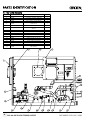
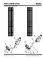
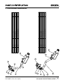
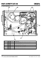
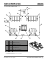
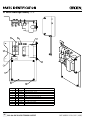
1
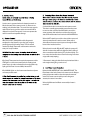
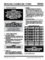
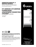
SERVICE MANUAL
IMPORTANT INFORMATION, KEEP FOR OPERATOR
This manual provides information for:
MODELS SSB-3E/5E/10EF,
(2)SSB-3E/5E/10EF,
SSB-3G/5G/10GF,
(2)SSB-3G/5G/10GF
· Self Contained
· Electric or Gas Heated
· Capacity:
3, 5 or 10 Steamer Pans Per Cavity
· Pans:
12” x 20” x 2.5”
Information contained in this document is known to be current and accurate at the time
of printing/creation. Unified Brands recommends referencing our product line websites,
unifiedbrands.net, for the most updated product information and specifications.
PART NUMBER 147423, REV. F (10/07)
1055 Mendell Davis Drive
Jackson, MS 39272
888-994-7636, fax 888-864-7636
groen.com
4
4
4
4
5
5
5
5
5
6
6
7
8
9
11
12
13
14
15
15
17
2
CALL 888-994-7636 FOR TECHNICAL SUPPORT
PART NUMBER 147423, REV. F (10/07)
CHECKOUT/ERROR CODES
23
24
30
31
32
34
RELAY BOARD
0
6.1
6.2
6.3
6.4
6.5
6.6
6.7
6.8
6.9
6.10
DOOR SWITCH
DOOR GASKET
FLOAT
GAS CAVITY ASSEMBLY
GAS OVERFLOW & CONDENSATE DRAIN
GAS HARNESSES
GAS HIGH VOLTAGE ASSEMBLY
BURNER ASSEMBLY
ELECTRIC CAVITY ASSEMBLY
ELECTRIC OVERFLOW & CONDENSATE DRAIN
ELECTRIC HARNESSES
ELECTRICAL VOLTAGE ASSEMBLY
ELEMENT BREAKDOWN
PART NUMBER 147423, REV. F (10/07)
35
35
35
35
36
36
37
38
38
39
39
39
40
42
43
44
45
46
47
49
50
52
55
CALL 888-994-7636 FOR TECHNICAL SUPPORT
3
100
100
4
CALL 888-994-7636 FOR TECHNICAL SUPPORT
PART NUMBER 147423, REV. F (10/07)
PART NUMBER 147423, REV. F (10/07)
CALL 888-994-7636 FOR TECHNICAL SUPPORT
5
6
CALL 888-994-7636 FOR TECHNICAL SUPPORT
PART NUMBER 147423, REV. F (10/07)
TIME display
2.1 Controls
Operator controls are on the front right of the unit.
The SmartSteam100 control panels have the following touch pads and
indicator lights:
• The TIME display shows the remaining cooking time. It
displays three dashes in MANUAL mode.
• The ON/OFF rocker switch gets the SmartSteam100 ready for
use or shuts it off.
• The READY indicator light indicates the unit has
achieved the ready temperature.
• Hour meter records cumulative hours of operation.
• The FAULT display shows the current fault.
The push button operations:
1. In the STOP mode the steam generator stays at a low boil
or ready temperature.
2. When the TIMED button is pushed , the TIMED light will illuminate
and time can be set by turning the TIMER knob. The unit steams until
the timer counts down to zero and the temperature drops to ready.
At that time the STOP light illuminates and a beeper sounds.
3. When the MANUAL button is pushed, the unit steams continuously.
The MANUAL light will stay illuminated.
4. CANCEL button should be pushed to stop beeping.
TIMER knob
MANUAL button
and indicator
TIMED button
and indicator
STOP button
and indicator
CANCEL button
and indicator
FAULT display
READY indicator
ON/OFF
rocker switch
Hour meter
PART NUMBER 147423, REV. F (10/07)
CALL 888-994-7636 FOR TECHNICAL SUPPORT
7
1. Press the ON/OFF rocker to the ON position,
“Fi ” is displayed in the TIME display window.
The steam generating reservoir will begin
filling, displaying “Fi ” and “Fi ” as it fills.
After initial fill, the unit will begin draining,
displaying “Fi ”, refill displaying “Fi ”, and
begin heating until the READY light comes
on (about 15-20 minutes).
2. Load food into pans in uniform layers. Pans
should be filled to about the same levels,
and should not be mounded.
3. Open the door and slide the pans onto the
supports. If you will only be steaming one
pan, put it in the middle position. Some
foods will cause foam. When cooking foods
that foam, such as shrimp, put an empty
solid 2 ½ “ deep pan in the bottom slot of the
pan racks.
4. Close the door. When the READY indicator is lit,
take one of the following steps:
!
If you want to steam the food for a
certain length of time, push the TIMED button
and set the desired time with the TIMER knob.
The timer will automatically run the steamer
for the set time and then go into STOP. A beeper
will sound. Then push CANCEL to stop beeping.
!
If you want to steam continuously, push
MANUAL button. The unit will continue
steaming until stopped.
!
Push STOP to stop producing steam.
WARNING
WHEN YOU OPEN THE DOOR, STAY AWAY
FROM THE STEAM COMING OUT OF THE UNIT.
THE STEAM CAN CAUSE BURNS.
5. To remove pans from cavity, open the door.
Remove the pans from the steamer, using
hot pads or oven mitts to protect your hands
from the hot pans.
6. To shut off the unit, press the ON/OFF rocker
switch to OFF, “FL ” will appear in the TIMER
display. The steam generating reservoir will
begin draining, displaying “FL ” and “FL ” as
it drains and refills to the Hi float twice and finally
drains completely and turns off the display.
NOTE: If a large amount of shrimp is cooked in the
SmartSteam100, foaming will occur because the
steam lid actually gets so hot that the shrimp will
cook on its surface and the shrimp proteins in the
dripping will foam on the surface of the steam lid.
* To avoid this, use a catch pan to catch shrimp
drippings and proteins to prevent foaming when
cooking a large amount of shrimp.
NOTE: When filling or draining the steam
generating reservoir, “ ” will be displayed
indicating the water level inside the reservoir,
“ ” when the cavity is empty, “ ” when the low
float is satisfied, and “ ” when the hi float is
satisfied.
Hi Float
Low Float
Empty
8
CALL 888-994-7636 FOR TECHNICAL SUPPORT
PART NUMBER 147423, REV. F (10/07)
2.3
Typical Operations
The following is a sequence of events typical to
SmartSteam100 Boilerless Steamers.
1. Cooking Food
To use the steamer, the cavity door is closed, the ON/OFF
rocker switch is set to ON. The unit verifies the floats and
drain using the following sequence. The drain valve is
closed and the water enters the steam reservoir to the “fill”
point. When the water level reaches the HIGH level float,
the water fill valve closes and the drain valve opens until
water drops off the HIGH float. At this point, the drain
valve closes and the water valve opens to refill the HIGH
float and the heater will operate. When the water reaches
the HIGH float, the water fill valve closes – stopping the
entry of water into the steam reservoir.
A relay (electric) or gas valve (gas) energizes and provides
power to the heating circuit for the steam reservoir. This
heats the steam reservoir to boil the water – creating the
required steam. When the cavity is heated to about 180F,
the READY indicator light comes on – indicating that the
cooking can start. When it is desired to cook food in the
cavity, the pans are inserted into the cavity and the door is
closed.
Heat-up time is about 20 minutes after the ON switch is
pressed, if all of the above conditions are met.
When the MANUAL button is pushed, its light turns on, the
display shows three dashed, and the heater turns on
continuously. This produces full steam.
When the TIMER button is pushed its light turns on, the
display shows time in hours and minutes, the heater turns
on producing full steam, and the timer counts down to
zero. At any time while in timed mode, the timer knob can
be turned to increase or decrease the remaining time.
When the door is open the display shows DOR, the timer
stops counting down, and the heater stops heating. Close
the door to resume timing and heating.
When the timer counts down to zero the display shows
three dashes, the beeper sounds, and the heater cycles on
and off slowly to keep the water temperature just above
the ready temperature. Push the CANCEL button to stop
PART NUMBER 147423, REV. F (10/07)
the beeper.
The STOP button may be pushed at any time to stop the
MANUAL or TIMED modes.
If the door is opened during the cooking process, the door
interlock switch causes power to be removed from the
convection motor. The relay or gas valve opens the circuit
to the source of heat, instantly reducing the heat from the
steam reservoir.
2. Water Entry Into Steam Reservoir
On power up, the boiler goes through a fill/drain diagnostic to verify the condition of the water level float and drain.
If either float is not responding, a service error is
generated.
CAUTION: A scaled reservoir or debris will cause service
errors. When a float has excessive scale it will not function
properly.
NOTICE: When powered off, the controls empty the
steam reservoir.
The HIGH WATER float determines if there is a full and
proper level of water in the steam reservoir. If the water
level goes down, the float is opened by the water level
getting low. This causes the water fill valve for that steam
reservoir to turn on to permit water to enter the steam
reservoir.
Water will continue to enter the steam reservoir until the
level of water is high enough to close the HIGH WATER
float. This determines that the steam reservoir is full and
then the water supply solenoid valve is turned off
stopping the water flow to the steam reservoir.
When the HIGH WATER float is open, there is a 3 to 5
second delay before the water fill valve opens. This is to
take into account the rising and lowering of the water
level due to the bubbling action of the boiling water in
the steam reservoir. If the float is open for more than
approximately 5 seconds, then the water fill valve is
activated.
CALL 888-994-7636 FOR TECHNICAL SUPPORT
9
A service error is generated when the electronic controls are
blind to the status of the steam reservoir (i.e., floats are not
working) or by a blocked drain. The service error may stop the
machine from running and the service error number will be
displayed in red on the front panel. Service error protects the
steam reservoir from irreparable damage.
After the reservoir is initially filled and the diagnostic is
complete, the relay (electric) or gas valve (gas) energizes
providing power to the heating circuit. Then the control
monitors the Ready Thermostat and determines when the
cavity is in “ready” condition.
If the Ready Thermostat is at the required temperature and the
STOP light is on, the heater control cycles the heating circuit
power relay or gas valve and maintains the ready condition by
cycling the elements 18 seconds ON, 6 minutes OFF.
If the MANUAL light is on, the heater control continuously turns
on heat to produce steam.
A solenoid drain valve is connected to each steam reservoir.
This valve is normally open permitting water from the steam
reservoir to drain out. When the ON switch is pressed, the
steam generator drain valve closes and the steam reservoir
starts to fill until the water level reaches the HIGH WATER float.
When the OFF switch is pressed, the solenoid valve opens and
drains the water from the steam reservoir. When water is
drained from the steam reservoir, it passes through the drain
box and then into the drain line.
When the unit is turned off by the OFF switch, the system will
drain for 3 minutes then refill to the high float, drain, refill, and
drain a second time while showing “FL” in the time display. This
is to remove the heat from the reservoir for cleaning and reduce
any possible cavity warping.
* If hot water is exiting, the drain fan thermal switch could close
and energize circuit giving a service error 7.
Below the HIGH WATER FLOAT is the LOW WATER FLOAT. This
float detects a low level of water in the steam reservoir. Because
prolonged operation with less than the required amount of
water in the steam reservoir could present a dangerous
situation, the action is immediate.
When the LOW water level float is uncovered,the heater is
turned off.
10
CALL 888-994-7636 FOR TECHNICAL SUPPORT
PART NUMBER 147423, REV. F (10/07)
Each SmartSteam100 Boilerless Steamer, including
To avoid drainage problems,
level the unit front to back,
and pitch it slightly to the front.
PART NUMBER 147423, REV. F (10/07)
SSB-10E
SSB-10E
208 3-PHASE
240 3-PHASE
59
51
3.5
4.7
SSB-10E
480 3-PHASE
26
18.5
CALL 888-994-7636 FOR TECHNICAL SUPPORT
11
To avoid drainage problems,
level the unit front to back,
and pitch it slightly to the front.
12
CALL 888-994-7636 FOR TECHNICAL SUPPORT
10G Natural
100,000
4.30” WC
5” WC
14” WC
10G Propane
100,000
10.5” WC
12” WC
14” WC
PART NUMBER 147423, REV. F (10/07)
100
100
1]
”
18
PART NUMBER 147423, REV. F (10/07)
CALL 888-994-7636 FOR TECHNICAL SUPPORT
[45
13
Refer to section 3.3 for proper clearances.
in section 3.3.
in section 3.2.
14
CALL 888-994-7636 FOR TECHNICAL SUPPORT
PART NUMBER 147423, REV. F (10/07)
100
If unit has a code, turn off at rocker switch. Open the steamer door.
cleaning. Replace steam lid after cleaning.
Your SmartSteam100 Boilerless Steamer is now ready to use.
Press OFF to turn the steamer off. Open the door.
WARNING
DO NOT DISASSEMBLE FLOAT PROBES DURING CLEANING, BREAKAGE WILL RESULT. USE HOT WATER TO
WASH OUT PIVOT JOINTS OF FLOAT.
(HCl).
PART NUMBER 147423, REV. F (10/07)
CALL 888-994-7636 FOR TECHNICAL SUPPORT
15
SmartSteam100 steamers are designed to require only a daily
cleaning of the steamer cavity, pan racks, steam lid and floats to
maintain full performance. Daily cleaning may not be sufficient
to control scale build-up, when a SmartSteam100 steamer is
operated in a heavy duty, continuous operation in an area with
extreme hard water.
Press OFF to turn the steamer off. Open the steamer door.
Add 1 cup of delimer/descaler (or vinegar) to the water in
the steam reservoir, push TIMED, and set the timer for 20 minutes.
Close the steamer door.
16
CALL 888-994-7636 FOR TECHNICAL SUPPORT
PART NUMBER 147423, REV. F (10/07)
PART NUMBER 147423, REV. F (10/07)
CALL 888-994-7636 FOR TECHNICAL SUPPORT
17
18
CALL 888-994-7636 FOR TECHNICAL SUPPORT
PART NUMBER 147423, REV. F (10/07)
PART NUMBER 147423, REV. F (10/07)
CALL 888-994-7636 FOR TECHNICAL SUPPORT
19
20
CALL 888-994-7636 FOR TECHNICAL SUPPORT
PART NUMBER 147423, REV. F (10/07)
PART NUMBER 147423, REV. F (10/07)
CALL 888-994-7636 FOR TECHNICAL SUPPORT
21
22
CALL 888-994-7636 FOR TECHNICAL SUPPORT
PART NUMBER 147423, REV. F (10/07)
4.1 SSB Checkout
1. Apply power to the SSB. On the back of the front-panel control board,
flip the left DIPswitch up to start the diagnostics.
2. The red 7-segment display on the front panel should have some of its
segments lit. If they are not then check the fuse and circuit breaker
on the control transformer. Then check that all harnesses are in place
and that the connectors are properly seated. Check for 24 VAC at the
secondary of the control transformer.
3. Turn the knob so that the red display shows A3 (Analog 3 – Control
board temperature). The green display should show approximately 75.
4. Turn the knob to A4 (Analog 4 – Line voltage). The green display should
show the approximate line voltage. It may read quite high.
5. Turn the knob to b (button). Push each button. The light near the button
should light. Also, check that pushing the top two buttons makes the
bottom two lights go out.
6. Turn the knob to F (Firmware version). The green display should show
version 1.18 or greater. Upgrade the code (swap the board) if the version
is incorrect.
7. Turn the knob to P (Product code). The green display should show 008
for an SSB-G or 009 for an SSB-E. If any other number is displayed the
ribbon cable connecting the front-panel control board to the relay
board is incorrect.
8. Turn the knob to S (Sensors). As each sensor is activated the associated
green bar will light. If it doesn’t then that sensor or harness connection
is faulty. Refer to this diagram:
Hi Float
Lo Float
Door Open
Box Temp
Overtemp
Ready
Power
9. Lift the hi float. The Hi Float bar should light. Release the float.
10. Lift the lo float. The Lo Float bar should light. Release the float.
11. Close and open the door. The Door Open bar should go out when the
door is closed. Use a magnet to check the door switch on the other side.
The bar should go out when the magnet is near the door sensor.
12. Push the ON end of the rocker switch. The Power bar should light. Push
the OFF end of the switch. The bar should go out.
13. On the left side of the SmartSteam100, near the two water valves,
disconnect one of the terminals on the overtemp thermostat. The
Overtemp bar (the one in the middle of the display) should light.
Reconnect the terminal. The Overtemp (middle) bar should go out.
14. Use needle nose pliers or a jumper to short the thermostat on top of
the drain box. The Box Temp (top) bar should light. Remove the pliers or
jumper. The Box Temp (top) bar should go out.
15. Turn the knob to O1 (Output 1 - Shutdown). Push the ON (upper) end
of the rocker switch. A relay on the Relay Board should pull in. Push the
MANUAL button. The relay should drop out.
PART NUMBER 147423, REV. F (10/07)
16. Turn the knob to O2 (Output 2 – Fill valve). Push the MANUAL button a
few times. The fill valve should open whenever the button is pushed.
17. Turn the knob to O3 (Output 3 – Spray valve). Push the MANUAL button a
few times. The spray valve should open whenever the button is pushed.
18. Turn the knob to O4 (Output 4 – Drain valve). Push the MANUAL button a
few times. The drain valve should open whenever the button is pushed.
19. SSB-E Turn the knob to O6 (Output 6 - Heater). Push the ON end of the
rocker switch. Lift the lower float all the way up and hold it up. Push the
MANUAL button a few times. The large contactor on the high voltage
panel should pull in whenever the button is pushed. Check for proper
line current on all three phases when the button is pushed. Note: For
the heater to turn on the power must be on, the lower float must be up,
and the overtemp thermostat must be operating properly.
20. SSB-G Turn the knob to O6 (Output 6 - Burner). Push the ON end of the
rocker switch. Lift the lower float all the way up and hold it up. Push the
MANUAL button and hold it in. The burner should light. Carefully check
the flue to verify flame. Release the MANUAL button to turn off the burner.
Note: For the burner to turn on the power must be on, the lower float must
be up, and the overtemp thermostat must be operating properly.
21. Turn the knob to O7 (Output 7 – Fan). Push the MANUAL button. The fan
should run.
22. Turn the knob to O8 (Output 8 – Beeper). Push the MANUAL button. The
beeper should beep.
23. Turn the knob to 88. All lights and all display segments should light.
24. On the back of the front-panel control board, flip the left DIPswitch
down to start normal SSB operation. The red heartbeat LED on the back
of the control board should blink about once a second.
25. Perform the normal SSB checkout (fill, check steam production, drain, etc.).
Diagnostic Switch Summary
A1 Analog 1 – RTD temperature (VRC only)
A2 Analog 2 – RTD millivolts (VRC only)
A3 Analog 3 – Control board temperature
A4 Analog 4 – Line voltage
b Button test
F Firmware version
O1 Output 1 – Shutdown
O2 Output 2 – Fill valve
O3 Output 3 – Spray valve (SSB only)
O4 Output 4 – Drain valve (SSB only)
O5 Output 5 – Eductor valve
O6 Output 6 – Heater (ON and low float up)
O7 Output 7 – Fan
O8 Output 8 – Beeper
P Product code
S Sensor outputs
88 All lights on
Error Codes
1 Lo float changed state while hi float on, Fatal
2 Hi float changed state while lo float off, Fatal
3 Cold fill to hi float time exceeded, Fatal
4 Hot refill to hi float time exceeded, Fatal
5 Controller temperature exceeded, Fatal
6 Cavity temperature exceeded, Fatal
7 Drain box temperature exceeded
8 Drain time exceeded
9 RTD is open (VRC only), Fatal
10 RTD is shorted (VRC only), Fatal
11 Control board is too hot, Fatal
99 No product code in connecting cable, Fatal
Product Codes
1 VRC manual fill
3 VRC auto fill
8 SSB gas
9 SSB electric
CALL 888-994-7636 FOR TECHNICAL SUPPORT
23
4.2 Procedures
open door, push OFF switch.
24vac on secondary transformer.
Heartbeat LED on back of control
240
24 volt control transformer
Control board or Relay board
Press ON switch
LEDs on control board illuminate.
24 volt control transformer
Service code 6. Measure for
continuity, normally closed.
Run sensor diagnostic.
Control board or Relay board
Run sensor diagnostic
24
CALL 888-994-7636 FOR TECHNICAL SUPPORT
PART NUMBER 147423, REV. F (10/07)
Run drain valve diagnostic.
Control board or Relay board
Run sensor diagnostic.
20
PART NUMBER 147423, REV. F (10/07)
CALL 888-994-7636 FOR TECHNICAL SUPPORT
25
Run spray valve diagnostic
Push TIMED and set timer to
1 minute.
Timer times out and unit beeps
until CANCEL is pushed.
Push MANUAL and let tun for
about 10 seconds.
Relay board
Turn rocker switch OFF.
Cavity drains.
Run fan diagnostic, substitute to test
24
Run drain valve diagnostic
26
CALL 888-994-7636 FOR TECHNICAL SUPPORT
PART NUMBER 147423, REV. F (10/07)
Measure input voltage and amps.
Input voltage is within 10% of rated
voltage and 15 amps.
Wrong model (voltage) installed to
incoming power supply.
Verify gas supply Propane or Natural,
and pressures.
Correct gas source and pressure.
Wrong model ordered.
Gas conversion not performed in
the field.
Disconnect or turn off water supply,
open door, push OFF switch.
24vac on secondary transformer.
Heartbeat LED on back of control
board flashes once a second.
24 volt control transformer
Measure 120vac in and
24vac +/- 20%vac out
Control board or Relay board
Press ON switch
LEDs on control board illuminate.
24 volt control transformer
Measure 120vac in and
24vac +/- 20%vac out
Service code 6. Measure for
continuity, normally closed.
Run sensor diagnostic.
Control board or Relay board
Run sensor diagnostic
PART NUMBER 147423, REV. F (10/07)
CALL 888-994-7636 FOR TECHNICAL SUPPORT
27
Run fill valve diagnostic.
Run drain valve diagnostic.
Audible click as gas valve opens.
Run sensor diagnostic.
Gas valve
Verify 24VAC across valve coil.
Gas valve
Verify 24VAC across valve coil.
20
28
CALL 888-994-7636 FOR TECHNICAL SUPPORT
PART NUMBER 147423, REV. F (10/07)
Check gas valve 24VAC and
gas supply.
Burners
Run spray valve diagnostic
Push TIMED and set timer to
1 minute.
Timer times out and unit beeps
until CANCEL is pushed.
Push MANUAL and let run for
about 10 seconds.
Relay board
Turn rocker switch OFF
Run fan diagnostic, substitute to test
24
Run drain valve diagnostic
PART NUMBER 147423, REV. F (10/07)
CALL 888-994-7636 FOR TECHNICAL SUPPORT
29
Empty to above hi float
Below lo float to above hi float
Below to above hi float
30
CALL 888-994-7636 FOR TECHNICAL SUPPORT
20 minutes
10 minutes
5 minutes
PART NUMBER 147423, REV. F (10/07)
AMPERAGE/RESISTANCE CHART
Model/Voltage/Phase
SSB-5E
208 Three Phase
SSB-5E
240 Three Phase
SSB-5E
480 Three Phase
SSB-5E
208 Single Phase
SSB-5E
240 Single Phase
SSB-3E
208 Three Phase
SSB-3E
240 Three Phase
SSB-3E
480 Three Phase
SSB-3E
208 Single Phase
SSB-3E
240 Single Phase
SSB-10E
208 Three Phase
SSB-10E
240 Three Phase
SSB-10E
480 Three Phase
Amperage
34
29
15
58
50
25
22
11
44
38
59
51
26
Resistance
6.1
8.3
32
3.6
4.8
8.3
10.9
43.6
4.7
6.3
3.5
4.7
18.5
GAS ORIFICE SIZE CHART (ALTITUDE ABOVE SEA LEVEL IN FEET)
Natural
Blank
0-2000
2001-4000
4001-6000
6001-8000
Propane
0-2000
2001-4000
4001-6000
6001-8000
5G Size
Blank
#39 (.0995)
#40 (.0980)
3/32 (.0938)
2.3 mm (.0906)
5G Size
1.65 mm (.0650)
1/16 (.0625)
1.55 mm (.0610)
1.50 mm (.0591)
PART NUMBER 147423, REV. F (10/07)
5G P/N
145645
145646
145647
145648
145649
5G P/N
145716
145717
145718
145719
10G Size
Blank
#41 (.0960)
3/32 (.0938)
2.25 mm (.0886)
2.15 mm (.0846)
10G Size
1.45 mm (.0571)
#54 (.0550)
1.35 mm (.0531)
#55 (.0520)
10G P/N
145645
145993
145648
145994
145995
10G P/N
145996
145997
145998
145999
3G Size
Blank
2.40 mm (.0945)
2.35 mm (.0925)
2.25 mm (.0886)
#44 (.0860)
3G Size
#53 (.0595)
1.50 mm (.0591)
1.45 mm (.0571)
#54 (.0550)
3G P/N
145645
147132
147133
145994
147134
3G P/N
145986
145719
145996
145997
CALL 888-994-7636 FOR TECHNICAL SUPPORT
31
HIGH FLOAT
LOW FLOAT
READY
DOOR
2
ROCKER
HOUR METER
SWI
1
KEY
1
2
3
4
5
6
7
8
9
10
11
12
13
14
GRN/YEL
T1
75 VA
TRANSFORMER
RED
RED
BROWN
BROWN
GRAY
GRAY
GRAY
GRAY
GRAY
GRAY
RED
BLACK
BROWN
15
16
17
FILL
VALVE
J3
SPRAY
VALVE
MUFFIN
FAN
HI
LIMIT
DRAIN
VALVE
DRAIN
BOX
11 10 9 8 7 6 5 4 3 2 1
160649 RELAY BOARD
GRAY
CALL 888-994-7636 FOR TECHNICAL SUPPORT
C B
4 A
K1
24 VAC
GRAY
J6
J3
KEY
BLACK
WHITE
WHITE
32
RED
BLACK
KEY
RED
1
2
3
4
5
6
7
8
9
10
11
12
13
14
J5
B
160649 RELAY BOARD
2A CB
B
B
YELLOW
OPTIONAL 480V
B
BLACK
BROWN
BLACK
BLACK
RED
RED
GRAY
GRAY
GRAY
GRAY
GRAY
GRAY
6
5
9
7
34
34
7
J4
J2
T2
STANDARD
208/240V
4
3
2
1
J2
5
4
3
2
1
6
8
7
9
10
11
12
13
14
J1
WHITE
BLACK
6A
MOTOR
VOLTAGE
SELECT
KEY
BLACK
ORANGE
CAP
RED
RED
BROWN
BROWN
VIOLET
BLUE
YELLOW
WHITE
F2
6A
F1
F1
F2
A
A
A
A
L2
L1
MI
MOTOR
H2
H3
H2
H1
OPTIONAL 208/240V
1 PHASE
H3
H1
STANDARD 208/240V
T1
T2
T3
T1
T2
T3
K1
K1
L1
L2
L3
L1
L2
L3
OPTIONAL 480V
H3
H2
H1
T1
T2
T3
K1
L1
L2
L3
X
L2
L1
1 PHASE
208/240V
TB1
X
L2
L1
GND
X
L2
L1
GND
X
L2
L1
3 PHASE
208/240/480V
TB1
SSB-3E/5E
PART NUMBER 147423, REV. F (10/07)
CONTROL BOARD 160648
4.4 Electric Models SSB-10E
PART NUMBER 147423, REV. F (10/07)
CALL 888-994-7636 FOR TECHNICAL SUPPORT
33
CALL 888-994-7636 FOR TECHNICAL SUPPORT
HIGH FLOAT
LOW FLOAT
READY
KEY
1
2
3
4
5
6
7
8
9
10
11
12
13
14
GRN/YEL
T1
75 VA
TRANSFORMER
RED
RED
BROWN
BROWN
GRAY
GRAY
GRAY
GRAY
GRAY
GRAY
RED
BLACK
BROWN
160649 RELAY BOARD
J3
11 10 9 8 7 6 5 4 3 2 1
FILL
VALVE
SPRAY
VALVE
MUFFIN
FAN
HI
LIMIT
DRAIN
VALVE
DRAIN
BOX
24 VAC
C B
4 A
BLACK
BROWN
BLACK
BLACK
RED
RED
GRAY
GRAY
GRAY
GRAY
GRAY
GRAY
6
5
9
7
KEY
1
2
3
4
5
6
7
8
9
10
11
12
13
14
J5
7
34
34
4
3
2
1
J2
5
4
3
2
1
6
8
7
9
10
11
12
13
14
WHITE
KEY
BLACK
MOTOR
VOLTAGE
SELECT
ORANGE
CAP
RED
RED
BROWN
BROWN
VIOLET
BLUE
YELLOW
MOTOR
MI
TR
TR
PILOT
MAIN
GAS VALVES
BLACK
BLACK
TH
TH
HOT SURFACE IGNITER
FLAME SENSOR
BROWN
5
DOOR
2
ROCKER
HOUR METER
SWI
1
15
16
17
KEY
BLACK
WHITE
WHITE
J1
BLACK
J4
RED
J2
M.V. 3
GRAY
J3
RED
J6
F1
6A
BLACK
34
THS 2
GRAY
SENSOR
RED
BLACK
IGNITER
L1
GROUND
PART NUMBER 147423, REV. F (10/07)
160649 RELAY BOARD
CONTROL BOARD 160648
BLACK
N
L1
N
L1
GND
120/60/1
TB1
IGNITER
WHITE
100
160648
Unplug the ribbon connectors.
2 Remove timer knob.
PART NUMBER 147423, REV. F (10/07)
CALL 888-994-7636 FOR TECHNICAL SUPPORT
35
Insert ribbon jack. Press firmly to make sure the jack is
fully seated on the board.
Replace the knob.
Relay Board P/N 160649
Unplug all connectors.
Using a 5/16” socket, remove fout 6/32” lock nuts
and remove the board from four studs on the high
voltage panel.
Position the board on four studs on the high voltage panel.
Insert all jacks in the same connector locations
36
CALL 888-994-7636 FOR TECHNICAL SUPPORT
PART NUMBER 147423, REV. F (10/07)
PART NUMBER 147423, REV. F (10/07)
CALL 888-994-7636 FOR TECHNICAL SUPPORT
37
38
CALL 888-994-7636 FOR TECHNICAL SUPPORT
PART NUMBER 147423, REV. F (10/07)
PART NUMBER 147423, REV. F (10/07)
CALL 888-994-7636 FOR TECHNICAL SUPPORT
39
40
CALL 888-994-7636 FOR TECHNICAL SUPPORT
PART NUMBER 147423, REV. F (10/07)
PART NUMBER 147423, REV. F (10/07)
CALL 888-994-7636 FOR TECHNICAL SUPPORT
41
ITEM NO.
1
2
3
4
42
PART NUMBER
160921
160648
149295
153505
5
160490
6
071234
7
160920
8
9
10
11
12
13
14
15
16
17
160721
160867
146880
143974
140172
143975
150672
140169
071235
140170
18
150659
DESCRIPTION
KNOB 1.5 DIAMETER
CONTROL BOARD, STEAMER
HOUR METER, REDINGTON, SSB
FAN, 24VDC MUFFIN 80MM
STEAMER HIGH VOLTAGE PANEL
ASSY SSB-G
VALVE-DRAIN 1/2" ID
ROCKER SWITCH FOR LATCHING
RELAYS
CABLE BRACKET
NATURAL WIRE STANDOFFS
MOTOR ASM, STEAMER BLOWER
HOSE, 1/2" ID DRAIN, SSB-3/5
HOSE, DRAIN
HOSE, SHORT 1/2" ID, FILL
HOSE, CONDENSATE DRAIN SSB
HOSE, DRAIN COOLING
VALVE-WATER FEED 3/4 R
HOSE, 3/8" ID, WATER FILL
WELDMENT, DRAIN MANIFOLD ASSY,
SSB-3/5E&G
CALL 888-994-7636 FOR TECHNICAL SUPPORT
QTY.
1
1
1
1
1
1
1
1
2
1
1
1
1
1
1
1
1
1
PART NUMBER 147423, REV. F (10/07)
PART NUMBER 147423, REV. F (10/07)
2
3
3
6
4
6
1
3
3
2
2
2
4
5
3
5
1
ITEM NO.
1
2
3
4
5
6
ITEM NO.
1
2
3
4
5
6
150659
142549
138457
150662
150628
150672
142549
138457
150662
150628
150661
150672
PART NUMBER
PART NUMBER
DESCRIPTION
WELDMENT, DRAIN MANIFOLD ASSY, SSB-3/5E&G
ELBOW 3/4" HOSE BARB
CLAMP, CONSTANT TENSION CTB-27
HOSE, CONDENSATE DRIP
DRAIN, CONDENSATE
HOSE, CONDENSATE DRAIN SSB
DESCRIPTION
ELBOW 3/4" HOSE BARB
CLAMP, CONSTANT TENSION CTB-27
HOSE, CONDENSATE DRIP
DRAIN, CONDENSATE
WELDMENT, DRAIN MANIFOLD ASSY
HOSE, CONDENSATE DRAIN SSB
QTY.
1
4
1
1
1
1
QTY.
1
4
1
1
1
1
6.2 Gas Overflow & Condensate Dain
CALL 888-994-7636 FOR TECHNICAL SUPPORT
43
6.3 Gas Harnesses
4
3
1
2
5
ITEM NO.
44
PART NUMBER
DESCRIPTION
QTY.
1
160885
HARNESS, SSB-G CONTROL TO RELAY BOARD
1
2
3
4
5
6
160883
160881
153339
153338
153118
HARNESS, SSB REAR
HARNESS, SSB-G LOW VOLTAGE
HARNESS, SSB-G IGNITION
HARNESS, SSB-G FORWARD
HARNESS, STEAMER 480-VOLT (NOT SHOWN)
1
1
1
1
1
CALL 888-994-7636 FOR TECHNICAL SUPPORT
PART NUMBER 147423, REV. F (10/07)
6.4 Gas High Voltage Assembly
7
8
3
13
12
10
4
5
1
9
ITEM NO.
1
2
3
PART NUMBER
160488
121716
096812
4
069789
5
6
7
8
9
005056
119855
140184
069790
160649
10
106412
11
12
13
14
160874
077840
002651
003887
PART NUMBER 147423, REV. F (10/07)
6
14
2
DESCRIPTION
HIGH VOLTAGE PANEL
TRANSFORMER, 75VAC
CAPACITOR FOIL 6 MFD
SCREW HEX SLOTTED WASHER HEAD
CAP
SCREW ROUND HEAD 8-32 1 1/4"
NUT, 6-32 LOCK INSERT
MODULE, IGNITION, HSI
SCREW HEX SLOTTED
RELAYBOARD, STEAMER
MECHANICAL LUG,GROUND, #2 #8
HARNESS, STEAMER HIGH VOLTAGE
FUSEBLOCK 1 POLE
FUSE 3 AMP BUSS #BAF-3
TERMINAL BLOCK 2-POLE
QTY.
1
1
1
5
1
4
1
2
1
1
1
1
1
1
CALL 888-994-7636 FOR TECHNICAL SUPPORT
45
6.5 Burner Assembly
See chart at end of section 4.3
46
CALL 888-994-7636 FOR TECHNICAL SUPPORT
PART NUMBER 147423, REV. F (10/07)
6.6 Electric Cavity Assembly
ITEM NO.
DESCRIPTION
QTY.
160489
STEAMER HIGH VOLTAGE PANEL ASSY
SSB-E
1
2
160920
ROCKER SWITCH FOR LATCHING
RELAYS
1
3
146880
MOTOR ASM, STEAMER BLOWER
1
4
071234
VALVE-DRAIN 1/2" ID
1
5
153505
FAN, 24VDC MUFFIN 80MM
1
6
160921
KNOB 1.5 DIAMETER
1
7
160648
CONTROL BOARD, STEAMER
1
8
149295
HOUR METER, REDINGTON, SSB
1
9
160721
CABLE BRACKET
1
10
160867
NATURAL WIRE STANDOFFS
2
11
150659
WELDMENT, DRAIN MANIFOLD ASSY,
SSB-3/5E&G
1
14
119833
TOROID ASM(480 VOLT ONLY)
1
13
071235
VALVE-WATER FEED 3/4 R
1
14
143974
HOSE, 1/2" ID DRAIN, SSB-3/5
1
15
140172
HOSE, DRAIN
1
16
143975
HOSE, SHORT 1/2" ID, FILL
1
17
150672
HOSE, CONDENSATE DRAIN SSB
1
18
140169
HOSE, DRAIN COOLING
1
19
140170
HOSE, 3/8" ID, WATER FILL
1
1
PART NUMBER
PART NUMBER 147423, REV. F (10/07)
CALL 888-994-7636 FOR TECHNICAL SUPPORT
47
6.6 Steamer Low Voltage Panel Assembly SSB-10E
B
7
2
16
12
B
SECTION B-B
SCALE 1 : 4
ITEM NO. QTY. PART NO. DESCRIPTION
2
7
12
5
5
1
119855
126026
149295
NUT, 6-32 LOCK INSERT
WASHER, #6 NYLON
HOUR METER, REDINGTON, SSB
13
15
16
0.02
1
1
149466
160921
160648
COMPOUND, RUBBER COATING
KNOB, 1.5 DIA
CONTROL BOARD, STEAMER
NOTES:
1.
APPLY ITEM #13, RUBBER COATING COMPOUND, TO BOTH ELECTRICAL
CONNECTION SCREWS AFTER HARNESS IS SECURED.
15
48
CALL 888-994-7636 FOR TECHNICAL SUPPORT
PART NUMBER 147423, REV. F (10/07)
PART NUMBER 147423, REV. F (10/07)
2
3
3
6
4
6
1
3
3
2
2
2
4
5
3
5
1
ITEM NO.
1
2
3
4
5
6
ITEM NO.
1
2
3
4
5
6
150659
142549
138457
150662
150628
150672
142549
138457
150662
150628
150661
150672
PART NUMBER
PART NUMBER
DESCRIPTION
WELDMENT, DRAIN MANIFOLD ASSY, SSB-3/5E&G
ELBOW 3/4" HOSE BARB
CLAMP, CONSTANT TENSION CTB-27
HOSE, CONDENSATE DRIP
DRAIN, CONDENSATE
HOSE, CONDENSATE DRAIN SSB
DESCRIPTION
ELBOW 3/4" HOSE BARB
CLAMP, CONSTANT TENSION CTB-27
HOSE, CONDENSATE DRIP
DRAIN, CONDENSATE
WELDMENT, DRAIN MANIFOLD ASSY
HOSE, CONDENSATE DRAIN SSB
QTY.
1
4
1
1
1
1
QTY.
1
4
1
1
1
1
6.7 Electric Overflow & Condensate Drain
CALL 888-994-7636 FOR TECHNICAL SUPPORT
49
6.8 Electric Harnesses SSB-3E/5E
1
6
5
4
2
3
ITEM NO. QTY. PART NO. DESCRIPTION
1
1
160884 HARNESS, SSB-E CONTROL TO RELAY BOARD
2
1
160883 HARNESS, SSB REAR
50
3
4
5
1
1
1
160882
160880
153486
HARNESS, SSB FORWARD
HARNESS, SSB-E LOW VOLTAGE
HARNESS, SSB HIGH VOLTAGE
6
1
153118
HARNESS, STEAMER 480-VOLT
CALL 888-994-7636 FOR TECHNICAL SUPPORT
PART NUMBER 147423, REV. F (10/07)
6.8 Electric Harnesses SSB-10E
PART NUMBER 147423, REV. F (10/07)
CALL 888-994-7636 FOR TECHNICAL SUPPORT
51
6.9 Electric High Voltage Assembly SSB-3E/5E
9
4
6
13
5
3
13
14
12
7
1
ITEM NO.
1
2
3
4
5
6
52
PART NUMBER
160488
121716
070185
145081
096813
116100
7
069789
8
9
10
11
005056
119855
003888
160649
12
106412
13
14
012864
160919
8
2
11
DESCRIPTION
HIGH VOLTAGE PANEL
TRANSFORMER, 75VAC
TERMINAL BLOCK 3 POLE
CONTACTOR, 50 FLA 3P HCOIL
CAPACITOR FOIL 3 MFD
SCREW TRUSS HD MACHINE #10-32
SCREW HEX SLOTTED WASHER HEAD
CAP
SCREW ROUND HEAD 8-32 1 1/4"
NUT, 6-32 LOCK INSERT
TERMINAL BLOCK 3-POLE
RELAYBOARD, STEAMER
MECHANICAL LUG,GROUND, #2 #8
BUSHING SNAP 11/16" ID
FUSE BLOCK ASSY
CALL 888-994-7636 FOR TECHNICAL SUPPORT
10
QTY.
1
1
1
1
1
2
7
2
4
1
1
1
2
1
PART NUMBER 147423, REV. F (10/07)
6.9 Electric High Voltage Assembly SSB-10E
10
9
SEE NOTE #1
11
3
8
8
3
7
14
13
2
8
5
6
4
2
ITEM NO. QTY. PART NO. DESCRIPTION
2
3
4
2
2
1
145081
070185
002577
CONTACTOR, 50 FLA 3P HCOIL
TERMINAL BLOCK, 3 POLE
TERMINAL BLOCK POWER
5
6
7
8
1
1
6
8
129714
097015
116100
069789
LUG GROUND #14-#6 AWG
BUSHING SNAP 1" I.D. X 1-3/8"
SCREW TRUSS MACHINE #10
SCREW HEX SLOTTED HD W/WASHER #8-32 X 3/8"
9
10
11
1
1
2
148440
003888
005056
PLATE, TERMINAL BLOCK
TERMINAL BLOCK 3-POLE
SCREW ROUND HEAD 8-32 1 1/4"
13
14
1
1
153700
160867
PANEL, HIGH VOLTAGE, SSB-10E
NATURAL WIRE STANDOFFS
NOTES:
1.) P/N'S (2) 005056, (2) 069789, 003888, 148440, (2) 007388RED,
TO BE ADDED FOR 277V ONLY.
PART NUMBER 147423, REV. F (10/07)
CALL 888-994-7636 FOR TECHNICAL SUPPORT
53
6.9 Electric Low Voltage Assembly SSB-10E
11
13
2
7
6
5
9
10
12
ITEM NO. QTY. PART NO. DESCRIPTION
54
2
5
6
1
1
2
121716
096813
069789
TRANSFORMER, 75VAC
CAPACITOR FOIL 3 MFD
SCREW HEX SLOTTED HD W/WASHER #8-32 X 3/8"
7
9
10
11
1
1
1
1
069788
153698
160649
160919
SCREW HEX SLOTTED WASHER HEAD CAP 6-32
PANEL, LOW VOLTAGE, SSB-10E
RELAYBOARD, STEAMER
FUSE BLOCK ASSY
12
13
4
2
119855
160867
NUT, 6-32 LOCK INSERT
NATURAL WIRE STANDOFFS
CALL 888-994-7636 FOR TECHNICAL SUPPORT
PART NUMBER 147423, REV. F (10/07)
6.10 Element Breakdown (Exploded View)
PART NUMBER 147423, REV. F (10/07)
CALL 888-994-7636 FOR TECHNICAL SUPPORT
55
56
CALL 888-994-7636 FOR TECHNICAL SUPPORT
PART NUMBER 147423, REV. F (10/07)
PART NUMBER 147423, REV. F (10/07)
CALL 888-994-7636 FOR TECHNICAL SUPPORT
57
58
CALL 888-994-7636 FOR TECHNICAL SUPPORT
PART NUMBER 147423, REV. F (10/07)
PART NUMBER 147423, REV. F (10/07)
CALL 888-994-7636 FOR TECHNICAL SUPPORT
59
1055 Mendell Davis Drive • Jackson MS 39272
888-994-7636 • 601-372-3903 • Fax 888-864-7636
groen.com
PART NUMBER 147423, REV. F (10/07)