1
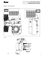
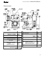
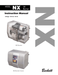
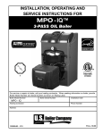
AFII
Oil
Burner
Instruction Manual
AFII
MODEL
AFII 85, AFII 100, AFII 150
Types “HLX” & “FBX” air tube combinations
Voltage: 120 Vac / 60 Hz
AFII burner with type “HLX” air tube
Type “FBX” air tube combinations
Beckett
Beckett
Instruction Manual – Model AFII Oil Burner
Contents
Prepare before installing
Verify specifications ……………………………….…………………..…….………….. 3
Be aware of hazard definitions …………….…………….…..………..……………….. 3
Check certifications/approvals ……………………………………..…………………... 3
Notice special requirements ………………….…………...…………..……………….. 3
Prepare burner & site
Inspect/prepare installation site ……………………...…………..………………….… 4
Prepare burner ……………………………...…..…………………..…………………… 5
HLX arrangement……………….…………….………………………..………………... 6
FBX arrangement …………………………………….….…………..………………….. 7
Adjust, pipe, & wire burner
Mount burner on appliance ………………………………..…………..……………….. 8
Connect fuel lines ………………………………………………………..……………… 8
Wire burner ………………………………………………………………..……………... 8, 9
Startup & adjust burner
Startup burner/set combustion ………..……………..….…………..…………………. 10
Set combustion with instruments …………..………….…………..…………………... 10
Service & maintain burner
Perform regular maintenance …………………..……….……………..……….……… 10
To replace the blower wheel ………………………..……………….…………………. 10
Replacement parts ………………………………………………………………………. 11
Owner’s information and warranty ………………………………….………….……… 12
Table 1 – Air Tube Combination (ATC) codes
AFII AIR TUBE COMBINATION AND FIRING RATE CHART
USABLE AIR TUBE LENGTH DIM. “A” (see Fig. 5)
3”
5”
7”
9”
ATC Code
FIRING RATE RANGE
Head
AFII 85
AFII 100
AFII 150
Head Design – Adjustable w/ stop screw – typical applications: Wet base boilers
HLX30
HLX50
HLX70
HLX90
HB
AF2-6
0.40-0.85 gph
0.65-1.00 gph
0.75-1.35 gph
HLX30
HLX50
HLX70
HLX90
HC
AF2-9
N/A
0.65-1.00 gph
0.75-1.50 gph
HLX30
HLX50
HLX70
HLX90
HD
AF2-6
0.40-0.85 gph
0.65-1.00 gph
0.75-1.10 gph
HLX30
HLX50
HLX70
HLX90
HE
AF2-9
N/A
0.65-1.00 gph
0.75-1.35 gph
Head Design – Fixed – typical applications: Furnaces, Dry base boilers, Water heaters
2
FBX30
FBX50
FBX70
FBX90
HFXS
FB0
0.40-0.65 gph
0.55-0.75 gph
0.75-1.00 gph
FBX30
FBX50
FBX70
FBX90
HGXS
FB3
0.55-0.85 gph
0.55-1.10 gph
0.85-1.20 gph
FBX30
FBX50
FBX70
FBX90
HHXS
FB4
N/A
0.75-1.10 gph
1.10-1.25 gph
FBX30
FBX50
FBX70
FBX90
HIXS
FB6
N/A
0.85-1.15 gph
1.15-1.35 gph
Beckett
Instruction Manual – Model AFII Oil Burner
Verify specifications
Be aware of hazard definitions
Capacity
Prepare before installing
“HLX” heads
Firing rate ..……..……………....…... 0.40 – 1.50 GPH
Input ..………..….…………… 56,000 – 210,000 Btu/h
“FBX” heads
Firing rate ..…..……………………… 0.40 - 1.35 GPH
Fuels
WARNING Denotes presence of a hazard which, if ignored, could result in
severe personal injury, death, or substantial property damage.
CAUTION
Denotes presence of a hazard which, if ignored, could result in
minor personal injury or property damage.
Input ..………….…..………….56,000 – 189,000 Btu/h
NOTICE
Intended to bring special attention to information, but not
related to personal injury or property damage.
U. S. …. No. 1 or No. 2 heating oil only (ASTM D396)
Check certifications/approvals
Canada ….... No. 1 stove oil or No. 2 furnace oil only
Electrical
DANGER
Denotes presence of a hazard which, if ignored, will result in
severe personal injury, death, or substantial property damage.
•
Power supply ....…….... 120 VAC/60 Hz/single phase
Operating load ……….… 5.8 Amps maximum; Note 1
Motor …..……… ……………………..1/7 hp, 3450 rpm
……….……...…… rotation CW when facing shaft end
Ignition .……... Continuous duty iron-core transformer
OR ………..... Continuous duty solid state igniter
Fuel unit
Outlet pressure ………..…..……………………. Note 2
Air tube
ATC code ……………………….. See Table 1, page 2
Dimensions
Height (maximum) ……….…….….…………13 inches
Width (maximum) ………….………..….. …..14 inches
Depth (chassis only) ………….……….6-11/16 inches
Air tube diameter ………………………….3 ½ inches
Note 1. A burner with an electronic igniter will have a lower operating current.
The actual load should be determined by a current meter.
Note 2. See appliance manufacturer’s burner specifications for
recommended outlet pressure. Pressure is 140 psig unless otherwise noted.
•
•
•
Underwriters Laboratories has certified this burner to comply with
ANSI/UL 296 and has listed it for use with #1 or #2 fuel oil as specified in
ASTM D396. Low sulfur #1 and #2 fuel oils reduce heat exchanger
deposits with all burners compared to the standard fuels. Reduced
deposits extend the service interval for cleaning and improve the
efficiency of the appliance over time. Low sulfur fuels reduce
particulate and oxides of nitrogen emissions as well. The Oilheat
Manufacturers' Association recommends these fuels as the
preferred fuels for this burner.
State and local approvals are shown on burner rating label (see below).
All oil burners should be installed in accordance with regulations of
the latest revision of the National Fire Protection Association
Standard NFPA 31 and in complete accordance with all local codes
and authorities having jurisdiction. Regulation of these authorities
take precedence over the general instructions provided in this
installation manual.
For recommended installation practice in Canada, refer to the latest
version of CSA Standard B139.
Notice special requirements
DANGER
This equipment must be installed, adjusted and started only
by a qualified service agency – an individual or agency, licensed and
experienced with all codes and ordinances, who is responsible for the
installation and adjustment of the equipment. The installation must comply
with all local codes and ordinances and with the latest revision of the National
Fire Protection Standard for Oil-Burning Equipment, NFPA 31 (or CSA B139).
WARNING
Read all instructions before proceeding. Follow all
instructions completely. Failure to follow these instructions could result in
equipment malfunction, causing severe personal injury, death or substantial
property damage.
Concealed damage — If you discover damage to the burner
NOTICE
or controls during unpacking, notify the carrier at once and file the appropriate
claim.
NOTICE
When contacting Beckett for service information — Please
record the burner serial number (and have available when calling or writing).
You will find the serial number on the silver label located on the top right of the
burner, to the left of the air dial. See illustration below.
SK9642
3
Beckett
Instruction Manual – Model AFII Oil Burner
Prepare burner & site
Inspect/prepare installation site
Inspect/prepare installation site (continued)
Chimney or vent
Exhaust fans and other air-using devices
•
•
Inspect the chimney or vent, making sure it is properly sized and in good
condition for use.
For those installations not requiring a chimney, such as through-the-wall
vented appliances, follow the instructions given by the appliance and
power venter (if used) manufacturers.
Size air openings large enough to allow for all air-using devices in addition
to the minimum area required for combustion air. If there is any possibility
of the equipment room developing negative pressure (because of exhaust
fans or clothes dryers, for example), pipe combustion air directly to the
burner.
Direct air supply and sidewall venting
•
•
When sidewall venting appliances, carefully follow appliance and power
venter instructions for installation and wiring.
AFII burners are equipped with a removable air inlet to allow use of a 4”
duct to supply outside air for combustion. Do not exceed 70 equivalent
feet. Allow 6 feet for each elbow.
1. Remove the inlet cover.
2. Insert 4" duct into the inlet ring.
3. Fasten duct into place using at least 3 sheet metal screws evenly
spaced around the inlet ring. Refer to Figure 1.
4. Remove the barometric draft control unless it is in the same
atmospheric pressure zone as the inlet.
On the outside of the home use a 90° elbow pointed downward with a 1/4"
mesh screen over its opening. The air inlet elbow must be located above
the snow line and in such a way as to prevent leaves and/or other debris
from blocking the air flow. Such debris will prevent proper operation of the
burner. Refer to local codes for proper location of inlet.
Figure 1 – Outside air connection
4 IN. DUCT
AIR
INLET
ELBOW
Clearances to burner and appliance
•
Provide space around burner and appliance for easy service and
maintenance.
•
Check minimum clearances against those shown by the appliance
manufacturer and by applicable building codes.
Combustion chamber — Burner retrofitting
Verify that the appliance combustion chamber provides at least the minimum
dimensions given in Table 2.
CAUTION
When retrofitting an appliance that has an unlined stainless
steel combustion chamber, chamber burnout could result from the use of a
high performance burner. Protect the chamber from high temperatures
through the use of "wet-pac" or a similar ceramic liner. Some equipment may
utilize a stainless steel combustion chamber that has been designed and
tested by the manufacturer for use with a flame retention burner, therefore
ceramic protection would not be necessary. Refer to appliance manufacturer’s
instructions. Failure to comply could result in damage to heating equipment.
Table 2 – Minimum combustion chamber dimensions
Chamber dimension (inches)
¼” MESH
SCREEN
INLET
RING
SK8810
Combustion air supply
See NFPA Standard 31 for complete details.
WARNING
If the burner is not supplied with a reliable combustion air
source, the burner cannot properly burn the fuel. This would result in
incomplete combustion, causing sooting and possible emission of carbon
monoxide. Severe personal injury, death or substantial property damage could
occur.
Appliance located in confined space
The confined space should have two (2) permanent openings: one near
the top of the enclosure and one near the bottom of the enclosure. Each
opening shall have a free area of not less than (1) one square inch per
1,000 BTU’s per hour of the total input rating of all appliances within the
enclosure. The openings shall have free access to the building interior,
which should have adequate infiltration from the outside.
4
Firing
rate
(gph)
Round
I.D.
0.50
Rectangular
Height
Floor to
nozzle
Width
Length
8
7
8
12
5-6
0.75
9
8
9
12
5-6
1.00
10
9
10
12 ½
5-6
1.25
11
10
11
12 ½
5-6
1.50
12
11
12
13
6-7
Beckett
Prepare burner
Instruction Manual – Model AFII Oil Burner
Prepare burner & site
•
Burner fuel unit
•
Verify that the burner fuel unit is compatible with the oil supply system. For
more details, refer to “Connect fuel lines” on page 8.
•
Attach air tube (if not already installed)
Use a wrench or vise to hold the nozzle adapter. DO NOT attempt to
remove or replace nozzle without holding adapter. The nozzle alignment
could be seriously damaged. Use a nozzle wrench that secures the
adapter or use 3/4" and 5/8" open-end wrenches.
Do not squeeze the electrodes too tightly when handling the nozzle line
assembly. This could change the electrode tip settings or damage the
ceramic electrode insulators.
Carefully check and realign electrode tips after replacing nozzle,
ensuring the electrode settings comply with Figure 2a or 2b.
If using a flange and gasket, slide them onto the air tube. Then attach the air
tube to the burner chassis using the sheet metal screws provided. See Figures
3 & 4 on pages 6 & 7 for details.
•
Install burner nozzle (if not already installed)
Check/adjust electrodes
WARNING Make certain the nozzle is selected for the fuel unit pressure
used. For applications with fuel unit pressure above 100 psig, the nozzle rated
capacity will be less than the appliance firing rate. Use only the specified spray
pattern unless combustion test results indicate the need for a change. Failure
to use the correct nozzle size and type can result in unacceptable combustion,
possibly causing severe personal injury, death or substantial property
damage.
1. Remove the plastic plug protecting the nozzle adapter threads
2. Place a ¾” open-end wrench on the nozzle adapter. Insert the nozzle into
the adapter and finger tighten. Finish tightening with a ⅝” open-end
wrench. Use care to avoid bending the burner head support legs or
electrodes. See CAUTION, below.
3. If you remove the head to replace the nozzle (type “HLX” heads), carefully
reconnect the head to the nozzle adapter, making sure to butt the head
support to the nozzle adapter shoulder (see Figure 3, page 6).
Check the electrode tip settings. Adjust if necessary to comply with the
dimensions shown in Figure 2a or Figure 2b. To adjust, loosen the electrode
clamp screw and slide/rotate electrodes as necessary. Securely tighten the
clamp screw when finished.
Figure 2a – Electrode settings – HLX Air Tube Combinations
If the nozzle is already installed, remove the nozzle line assembly to verify that
the nozzle size and spray pattern are correct for the application (per appliance
manufacturer’s information or Beckett OEM Specification Guide, part number
6711). Verify that the electrode tip settings comply with Figure 2a or 2b.
SK8263
If the nozzle is not installed, obtain a nozzle of the manufacturer, capacity and Figure 2b – Electrode settings – FBX Air Tube Combinations
spray angle specified in appliance manufacturer’s information or Beckett OEM
Specification Guide, part number 6711. For conversions or upgrades, when
information is not available for the application:
4. Refer to table below to select the mid-range nozzle spray angle for the
head type being used.
5. Fire the burner and make sure the combustion is acceptable and the
flame is not impinging on chamber surfaces.
6. If a shorter flame is needed, select a wider spray angle. If a longer flame
is needed, select a narrower spray angle.
7. Either hollow or solid spray patterns may be used. If combustion results
SK8811
are not satisfactory with the selected spray pattern, try the other pattern.
Recommended nozzle spray angles
45°, 60°, or 70° nozzle
“HLX” heads
60°, 70°, or 80° nozzle
“FBX” heads
Use care when removing and installing oil nozzles:
Inspect the nozzle adapter before installing nozzle. If it is grooved or
scratched on the sealing surface, replace the nozzle line assembly.
Otherwise, oil could leak at the nozzle-adapter joint, causing serious
combustion problems.
Protect the nozzle orifice and strainer when installing. If the orifice gets
dirt in it or is scratched, the nozzle will not function properly.
Do not over-torque the nozzle when installing. This will cause deep
grooves in the nozzle adapter, preventing a seal when a new nozzle is
installed.
CAUTION
•
•
•
Servicing nozzle line assembly
1.
2.
3.
4.
5.
Turn off power to burner before proceeding.
Disconnect copper oil connector tube from nozzle line.
Loosen the screw that fastens the rear access door.
Remove splined nut.
Remove the nozzle line assembly from the burner, being careful not to
damage the electrodes or insulators while handling. Stop halfway to
remove igniter/transformer wires.
6. To replace the nozzle assembly, reverse the above steps.
“HLX” head air tubes – Be sure stop screw is fastened securely. Seat
stop screw on back of choke ring to set the position of the head.
“FBX” head air tubes – Use T gauge to set the “Z” dimension to 1-1/8” +/1/32”.
5
Beckett
Instruction Manual – Model AFII Oil Burner
Prepare burner & site
Figure 3 - HLX Arrangement
FIRING
RATE
Stop Screw
AFII 85
AFII 100
AFII 150
0
0.40-0.65
0.50-0.65
0.75-1.00
1
-
0.60-0.75
0.85-1.10
2
-
0.65-0.80
0.95-1.15
3
0.60-0.75
0.65-0.90
0.95-1.20
4
-
0.75-0.95
1.10-1.25
5
0.70-0.85
0.85-1.00
1.15-1.35
6
-
0.95-1.10
1.15-1.40
7
-
-
1.25-1.50
8
-
-
1.30-1.50
Firing Rate at
140 psig
AFII 85
AFII 100
0.40 to 0.65
3
-
-
0.60 to 0.75
4
3
-
0.70 to 0.85
5
4
-
0.75 to 1.00
-
5
2
AFII 150
0.95 to 1.20
-
-
3
1.15 to 1.35
-
-
4
1.25 to 1.50
-
-
5
AIR
DIAL
SETTING
SK9644A
6
SK9639
Beckett
Instruction Manual – Model AFII Oil Burner
Prepare burner & site
Figure 4 - FBX Arrangement
FIRING
RATE
Head
AFII 85
AFII 100
AFII 150
Firing Rate at
140 psig
AFII 85
AFII 100
FB0
0.40-0.65
0.55-0.75
0.75-1.00
0.40 to 0.65
3
-
-
FB3
0.55-0.85
0.55-1.10
0.85-1.20
0.60 to 0.75
4
3
-
FB4
-
0.75-1.10
1.10-1.25
0.70 to 0.85
5
4
-
FB6
-
0.85-1.15
1.15-1.35
0.75 to 1.00
-
5
2
AFII 150
0.95 to 1.20
-
-
3
1.15 to 1.35
-
-
4
1.25 to 1.50
-
-
5
AIR
DIAL
SETTING
SK9644B
SK9641
7
Beckett
Instruction Manual – Model AFII Oil Burner
Adjust, pipe, & wire burner
Connect fuel lines (continued)
Mount burner on appliance
Mounting options
•
Bolt the burner to the appliance using the factory-mounted flange or an
adjustable flange.
Mounting dimensions
•
•
•
When using the Beckett universal adjustable flange, mount the air tube at
a 2° downward pitch unless otherwise specified by the appliance
manufacturer.
Verify that the air tube installed on the burner provides the correct
insertion depth. See Figure 5.
The end of the air tube should normally be ¼" back from the inside wall of
the combustion chamber. Never allow the leading edge of the head
assembly to extend into the chamber, unless otherwise specified by the
heating appliance manufacturer. Carefully measure the insertion depth
when using an adjustable flange. Verify the insertion depth when using a
welded flange.
Figure 5 – Mounting burner in appliance
WARNING
The oil supply inlet pressure to the fuel unit cannot exceed 3
psi. Install a pressure-limiting device in accordance with NFPA 31.
Fuel supply below the level of the burner
When the fuel supply is below the level of the burner, a two-pipe fuel supply
system is required. Depending on the fuel line diameter and horizontal and
vertical length, the installation may also require a two-stage pump. Consult the
fuel unit manufacturer's literature for lift and vacuum capability.
Fuel line installation
•
•
Continuous lengths of heavy wall copper tubing are recommended.
Always use flare fittings. Never use compression fittings.
Always install fittings in accessible locations. Fuel lines should not run
against the appliance or the ceiling joists (to avoid vibration noise).
WARNING
Never use Teflon tape on any fuel fitting. Tape fragments can
lodge in fuel line components and fuel unit, damaging the equipment and
preventing proper operation.
Fuel line valve and filter
•
Install two high quality shutoff valves in accessible locations on the oil
supply line. Locate one close to the tank and the other close to the burner,
upstream of the filter.
NOTICE
Some states require these valves to be fusible-handle design
for protection in the event of fire. We recommend this as good industry
practice for all installations.
• Install a generous capacity filter inside the building between the fuel tank
shutoff valve and the burner, locating both the filter and the valve close to
the burner for ease of servicing. Filter should be rated for 50 microns or
less.
Beckett
INLET
Wire Burner
USE ONLY WITH
VALVE ON DELAY
A2EA-6520
RPM
4 GPH 100-150 PSI 3450
FUEL
NO. 2 & LIGHTER
3 GPH 150-200 PSI 3450 RPM
NO. 2 FUEL
INLET
BY-PASS
Made by Suntec
Exclusively for Beckett
Burner packaged with appliance
• Refer to appliance manufacturer’s wiring diagram for electrical connections.
Burner applied at jobsite
SK8273
Connect fuel lines
Carefully follow the fuel unit manufacturer’s literature and the latest edition of
NFPA 31 for oil supply system specifications. If this information is unavailable,
use the following basic guidelines..
Fuel units with automatic bypass do not require a bypass plug.
NOTICE
•
Refer to Figures 6 and 7, page 9, for typical burner wiring, showing cad
cell primary controls. Burner wiring may vary, depending on primary
control actually used. The oil valve shown in Figures 6 and 7 may be an
optional feature.
NOTICE
All wiring must be in accordance with the latest revision of
National Electric Code NFPA 70 and local codes and regulations.
WARNING The wiring diagrams in this manual are for general reference
only, and apply only to burners equipped with R8184G or R7184 primary
controls. For other controls, refer to the control manufacturer’s literature or the
WARNING The burner fuel unit is shipped without the bypass plug installed.
diagrams supplied with the appliance. Failure to apply correct wiring could
You must install this plug on two-pipe oil systems. DO NOT install the plug in result in severe personal injury, death or substantial property damage.
the fuel unit if connected to a one-pipe oil system. Failure to comply could
NOTICE
The R7184 primary control with valve-on delay (prepurge) and
cause fuel unit seal failure, oil leakage and potential fire and injury hazard.
burner motor-off delay (postpurge), shown in Figure 7, page 9, requires a
Fuel supply level with or above burner
constant 120 VAC power source supplied to the BLACK wire on the control.
The burner may be equipped with a single-stage fuel unit for these The RED wire goes to the appliance limit circuit. Please note that other control
installations. Connect the fuel supply to the burner with a single supply line if manufacturers may use different wire colors for power and limit connections.
you want a one-pipe system (making sure the bypass plug is NOT installed in
the fuel unit.) Manual venting of the fuel unit is required on initial start-up. If
connecting a two-pipe fuel supply, install the fuel unit bypass plug.
8
Beckett
Instruction Manual – Model AFII Oil Burner
Adjust, pipe, & wire burner
Figure 6 – Typical wiring, R8184G or equivalent primary control
DANGER Electrical shock hazard. Disconnect
power before servicing.
SK9437
DANGER Electrical shock hazard. Disconnect
power before servicing.
Figure 7 – Typical wiring, R7184 or equivalent primary control
SK9359
Table 5 – R7184 primary control features
Feature
R7184A
R7184B
R7184P
Interrupted ignition
YES
YES
YES
Limited reset, limited recycle
YES
YES
YES
Diagnostic LED, cad cell indicator
YES
YES
YES
YES
YES
Valve-on delay
Burner motor-off delay
Alarm contacts
YES
Optional
9
Beckett
Instruction Manual – Model AFII Oil Burner
Startup & adjust burner
Startup burner/set combustion
Service & maintain burner
Perform regular maintenance
Do not attempt to start the burner when excess fuel or vapor WARNING This equipment must be serviced only by a qualified service
has accumulated in the appliance. Starting the burner under these conditions agency. The appropriate test instruments must be used. Failure to do so could
could result in a puffback of hot combustion gases, high smoke levels, or result in burner or appliance failure, causing potential severe personal injury,
otherwise hazardous operation.
death or substantial property damage.
1. Open the shutoff valves in the oil supply line to the burner.
Replace the oil supply line filter. The line filter cartridge must be replaced
2. Open the air dial. This is an initial air setting for the pump bleeding
to avoid contamination of the fuel unit and nozzle.
procedure only. Additional adjustments must be made with instruments.
Inspect the oil supply system. All fittings should be leak-tight. The supply
3. Set the thermostat substantially above room temperature.
lines should be free of water, sludge and other restrictions.
4. Close the line voltage switch to start the burner. If the burner does not
Remove and clean the pump strainer if applicable.
start immediately you may have to reset the safety switch of the burner
Replace the nozzle with an equivalent nozzle.
primary control.
Clean and inspect the electrodes for damage, replacing any that are
cracked or chipped.
5. Bleed air from the fuel unit as soon as burner motor starts rotating.
Check electrode tip settings. Replace electrodes if tips are rounded.
To bleed the fuel unit, attach a clear plastic hose over the vent fitting.
Inspect the igniter cables and connections.
Loosen the fitting and catch the oil in an empty container. Tighten the
Clean the cad cell grid surface, if necessary.
fitting when all air has been purged from the oil supply system.
Make sure the burner housing baffle is in place if required for the burner
• If the burner locks out on safety during bleeding, reset the safety
application (AFII 85 & AFII 100). Omitting the baffle can result in
switch and complete the bleeding procedure. Note — Electronic
unacceptable burner combustion.
safety switches can be reset immediately; others may require a threeInspect all gaskets. Replace any that are damaged or would fail to seal
to five-minute wait.
adequately.
• If burner stops after flame is established, additional bleeding is
Clean
the blower wheel, air inlet, air guide, and retention head of any lint
probably required. Repeat the bleeding procedure until the pump is
or foreign material.
primed and a flame is established when the vent fitting is closed.
If motor is not permanently lubricated, oil motor with a few drops of SAE
• For R7184 primary controls, see Technician’s Quick Reference Guide,
20 nondetergent oil at each oil hole. DO NOT over oil motor. Excessive
part number 61351 or 61465, for special pump priming sequence.
oiling can cause motor failure.
• Prepare for combustion tests by drilling a ¼" sampling hole in the flue
Check
motor current. The amp draw should not exceed the nameplate
pipe between the appliance and the barometric draft regulator.
rating
by
more than 10%.
6. Initial air adjustment — Using a smoke tester, adjust the air dial (and
Check all wiring for secure connections or insulation breaks.
change firing pin on HLX ATC’s, if necessary) to obtain a clean flame.
Check the pump pressure and cutoff function.
Now the additional combustion tests with instruments can be made.
Check primary control safety lockout timing.
Check ignition system for proper operation.
Set combustion with instruments
Inspect the vent system and chimney for soot accumulation or other
WARNING
The combustion must be adjusted using test instruments.
restriction.
Failure to do so could result in burner or appliance failure, causing potential
Clean the appliance thoroughly according to the manufacturer's
severe personal injury, death or substantial property damage.
recommendations.
1. Let burner run for approximately 5 to 10 minutes.
Check the burner performance. Refer to the section “Set combustion
2. Set the over-fire or stack draft to level specified by appliance manufacturer
with instruments”.
(usually –0.01 to –0.02 inches w.c. over-fire for natural draft applications).
It is good practice to make a record of the service performed and the
3. Follow these four steps to properly adjust the burner:
combustion test results.
Step 1: Adjust air until a trace smoke level is achieved
Step 2: At the trace of smoke level, measure the CO2 (or O2). This is To replace the blower wheel:
the vital reference point for further adjustments.
1. Turn off all power to the burner before servicing.
• Example: 13.5% CO2 (2.6% O2)
2. Disconnect the burner motor wires.
Step 3: Increase the air to reduce CO2 by 1 to 2 percentage points. (O2 3. Remove the bolts securing the blower motor to
the housing.
will be increased by approximately 1.4 to 2.7 percentage points.)
4. Remove the blower motor and wheel.
• Example: Reduce CO2 from 13.5% to 11.5%. (O2 – 2.6% to 5.3%)
5. Remove the existing wheel.
Step 4: Recheck smoke level. It should be zero.
6. As shown at right, slide the new blower wheel
• This procedure provides a margin of reserve air to accommodate
onto the shaft.
variable conditions.
• Place a .062" (1/16" ± 1/64") feeler gauge on
• If the draft level has to be changed, recheck the smoke and CO2
the motor as shown.
levels. Adjust the burner air if necessary.
• Slide blower wheel toward motor until it
4. Once combustion is set, tighten all fasteners on air dial, rear access door
contacts feeler gauge.
and escutcheon plate.
• Rotate the wheel until the setscrew is
5. Start and stop the burner several times to ensure satisfactory operation.
centered on the flat of the motor shaft.
SK9190A
Test the primary control and all other appliance safety controls to verify
Tighten the setscrew to secure the wheel.
that they function according to the manufacturer’s specifications.
7. DO NOT use any motor other than the original equipment type motor.
8. Install the motor on the burner housing. Tighten screws. Reconnect wires.
9. Restore power, start the burner and perform combustion tests. Refer to
the section “Set combustion with instruments”.
WARNING
10
Beckett
Instruction Manual – Model AFII Oil Burner
Replacement parts
SK8265B
PART DESCRIPTION
PART NO.
Air tube combination (ATC) – see Table 1
Specify
Blower wheel: AFII 85 (4¼” x 2” strip)
21439U
AFII 100 (4½” x 2” tablock)
21438U
AFII 150 (4½” x 2” tablock)
21438U
Box, 4x4 wiring
31613BK
Connector tube, 8” long, copper
5394U
Coupling, motor to pump
21437U
Electrodes: replacement kit (HLX heads)
51484U
replacement kit (FBX heads)
51670U
Escutcheon plate: AFII (blank)
31623
AFII (140 PSI)
3162302
Flange kit, adjustable 3½” I.D. with gasket
51480
Fuel pump: A2VA7116 (Suntec)
2460U
A2EA6520N621L (CleanCut)
2184404U
cordset
21808
BFPH071N1161 (Danfoss)
21391U
Gasket, flange
31658
Head (FBX): FB0, FB3, FB4, or FB6
Specify
Head (HLX) assembly: AFII 6 slot head
51671U
AFII 9&
slot
head tain51672U
Service
main
burner
PART DESCRIPTION
Head insulator kit (FB0, 3, 4, 6 heads only)
Igniter, AFII electronic
Inlet air scoop, plastic, sound insulated
Main housing assy, with hole plug: AFII 85
AFII 100
AFII 150
Motor: 1/7 hp, 3450 rpm, 115V / 60Hz
Nozzle adapter
Nozzle line electrode head assembly
Pedestal kit, AFII mounting
Primary R7184A - interrupted ignition
Control R7184B - valve-on delay
R7184P - valve-on/motor off delay
R7184P - with alarm contacts
Rear access door
Stop screw: replacement kit
Splined nut
PART NO.
51685
51805U
51485
51584U
51584U
51476U
21444U
213
Specify ATC
51481
7455U
7456U
7457U
7458U
51424U
51483
3666
11
Beckett
Instruction Manual – Model AFII Oil Burner
Service & maintain burner
Owner’s information
Owner service and maintenance
This burner must be installed, adjusted and started only by a
qualified service agency — an individual or agency, licensed and
experienced with all codes and ordinances, who is responsible for the
installation and adjustment of the equipment.
WARNING
Properly installed and maintained, your AFII burner will provide years of
efficient, trouble-free operation. Please take care of your equipment by
following the warnings provided and by doing the following (notify your
qualified service agency if you find anything wrong):
•
Have your equipment inspected at regular intervals by a qualified Regular Service
service agency to assure continued proper operation.
Have your burner/heating appliance serviced annually by your qualified
•
service agency, unless an extended service interval has been
• Installation and adjustment of the burner requires technical knowledge
determined as follows.
and the use of combustion test instruments. Do not tamper with the unit
or controls. Call your qualified service agency.
•
With properly configured burners, there are special Clearburn® practices
(such as low sulfur fuels, fuel additive programs, outside combustion air,
• Incorrect operation of the burner could result in severe personal
high effectiveness filtration, etc.) that can extend service intervals.
injury, death or substantial property damage.
Discuss this with your qualified service agency to determine the proper
regular service interval for your heating system.
The following could result in fire hazard, severe personal injury, death or
Daily
substantial property damage. Read carefully.
•
Check the room in which your burner/appliance is installed. Make sure:
• Never attempt to use gasoline in your heating appliance.
air ventilation openings are clean and unobstructed
• Never store gasoline or combustible materials near the burner or
nothing is blocking the burner inlet air openings
appliance.
no combustible materials are stored near the heating appliance
• Never attempt to burn garbage or refuse in your appliance.
there are no signs of oil or water leakage around the burner or
appliance
• Never attempt to light the burner/appliance by throwing burning material
into the appliance.
•
Never attempt to use crankcase or waste oil or material other than the
approved fuel oils in this burner.
•
Never restrict the air inlet openings to the burner or the combustion air
ventilation openings in the room.
Weekly
•
Check your oil tank level. Always keep your oil tank full, especially
during the summer, in order to prevent condensation of moisture on the
inside surface of the tank.
Warranty
Beckett warrants its equipment specifically to those who have purchased it for
resale, including your qualified service agency (dealer). In the event of any
problems with your equipment or its installation, you should contact your
dealer for assistance.
The Oilheat Manufacturers' Association supports the use of low sulfur fuels as defined by ASTM D396, Grades No. 1 Low Sulfur and No. 2 Low Sulfur, as
the preferred heating fuel for the following reasons:
• Low sulfur fuels reduce deposits on heat exchanger surfaces, extending the service interval between cleanings.
• The reduced deposits increase the efficiency of the appliance.
• Low sulfur fuels reduce particulate emissions.
• Low sulfur fuels reduce oxides of nitrogen emissions.
___________________________________________________________________
R.W. BECKETT CORPORATION
U.S.A.: P.O. Box 1289 • Elyria, Ohio 44036
Canada: R.W. Beckett Canada, Ltd. • Unit #3, 430 Laird Road • Guelph, Ontario N1G 3X7
Form Number 6104BAFII R0803
Printed in U.S.A.
12
© 2003 R.W. Beckett Corporation
Bar code