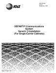
1
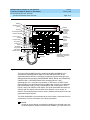
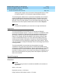
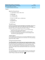
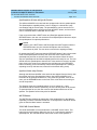
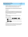
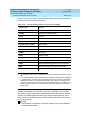
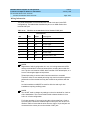
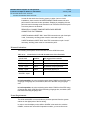
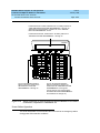
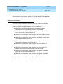
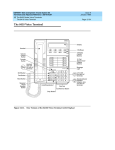
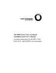
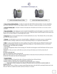
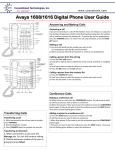
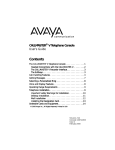
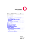
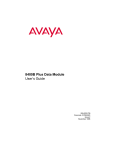
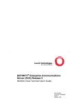
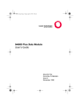
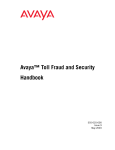
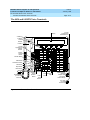
Issue 9
January 1998
DEFINITY ECS and System 75 and System 85
Terminals and Adjuncts Reference 555-015-201
12 The 8400 Series Voice Terminals
The 8434 and 8434DX Voice Terminals
Page 12-72
The 8434 and 8434DX Voice Terminals
24 Call
Appearance/
Feature Buttons
Display
4 Softkeys
4 Display
Control
Buttons
8434
Handset
10 Call
Appearance/
Feature
Buttons
Menu
Exit
Prev
Next
Volume
Control
Button
Transfer Button
Shift Button
Message
Volume
ABC
1
Conference Button
Shift
GHI
Test Button
Test
Conf
Drop Button
Mute
Drop
Speaker
Hold
Mute Button
Handset Jack
(on back of
terminal)
2
Transfer
Reset Spkr
Speaker/
Reset
Speaker
Button
Ring
Hold/
Ring
Button
JKL
4
5
PQRS
TUV
DEF
3
MNO
6
WXYZ
7
8
9
*
O
#
Dial
Pad
Message
Light
Speakerphone/
Headset
Adapter Jack
(on back of
voice terminal)
Line Jack
(on back
of terminal)
Figure 12-20.
The 8434 Voice Terminal
LINE
Issue 9
January 1998
DEFINITY ECS and System 75 and System 85
Terminals and Adjuncts Reference 555-015-201
12 The 8400 Series Voice Terminals
The 8434 and 8434DX Voice Terminals
Page 12-73
4 Softkeys
Display
4 Display
Control Buttons
Handset
10 Call
Appearance
Feature Buttons
EX MOD
Menu
Exit
Prev
Next
24 Call
Appearance/
Feature
Buttons
Volume Control
Button
Transfer Button
Shift Button
Conference
Button
Test Button
Drop Button
Mute Button
Handset Jack
(on back of
terminal)
Figure 12-21.
Expansion
Module Jack
(on back of
of voice
terminal)
Message
Volume
Shift
Transfer
1
Mute
Conf
Drop
Speaker Hold
Reset SpkrRing
Speaker/
Reset
Speaker
Button
DEF
2
3
LINE
GHI
Test
ABC
4
JKL
5
MNO
6
PQRS
TUV
WXYZ
7
8
9
*
O
#
Dial Pad
Hold/Ring
Button
Message
Light
One Version of the 8434DX Voice Terminal
Speakerphone/
Headset Adapter
Jack (on back
of terminal)
Line Jack
(on back
of voice
terminal)
Issue 9
January 1998
DEFINITY ECS and System 75 and System 85
Terminals and Adjuncts Reference 555-015-201
12 The 8400 Series Voice Terminals
The 8434 and 8434DX Voice Terminals
Page 12-74
Softkeys
Display control
buttons
Display
Handset
10 Call appearance/
feature buttons
EX MOD
Menu
Exit
Prev
Next
Expansion
module jack
(on back
of voice
terminal)
24 Call
appearance/
feature
buttons
Volume control
button
Transfer button
Ring button
Conference
button
Volume
Ring
Test button
Drop button
Mute button
Speaker button
Transfer
Test
Conf
Mute
Drop
Speaker Hold
ABC
DEF
1
2
3
GHI
JKL
MNO
4
5
6
LINE
PQRS
TUV
Line jack
(on back
of voice
terminal)
WXYZ
7
8
9
*
O
#
Dial pad
Message
light
Hold button
Speakerphone/headset
adapter jack (on back of
voice terminal)
Handset jack
Figure 12-22.
Another Version of the 8434DX Voice Terminal
The basic 8434 (8434D01A) and the enhanced 8434DX (8434D02A) voice
terminals are multi-appearance digital voice terminals which offer 34 call
appearance/feature buttons, each with a red light and a green status light, four
standard fixed feature buttons (CONFERENCE, DROP, HOLD, and TRANSFER),
a MUTE button, a SPEAKER button which accesses either a 2-way
speakerphone or a 1-way listen-only speaker, a TEST button, a SHIFT button
(some 8434DX voice terminals will have a RING button instead), a red Message
light, personalized ringing, a built-in speakerphone with a reset option, and a
built-in 2-line by 40-character VFD display. The 8434 and 8434DX also have five
softkeys and four display control buttons which allow the user to access 15
features. These softkey features can be used in addition to the features on the call
appearance/feature buttons.
The 8434 and 8434DX voice terminals can be used in both a 4-wire and a 2-wire
environment. For more information, see “Wiring Information.”
NOTE:
In order to use the display on the 8434 or 8434DX voice terminal and to use
an 801A expansion module connected to the 8434DX, you must connect an
DEFINITY ECS and System 75 and System 85
Terminals and Adjuncts Reference 555-015-201
Issue 9
January 1998
12 The 8400 Series Voice Terminals
The 8434 and 8434DX Voice Terminals
Page 12-75
auxiliary power supply to the voice terminal. Recommended are an 1151A1
local power supply or an 1151A2 power supply with Battery Holdover.
The 801A Expansion Module can be connected to the 8434DX voice terminal to
provide 24 additional call appearance/feature buttons. The 801A can be used
ONLY with the 8434DX voice terminal and the terminal must be connected to a
DEFINITY G3V3.3 (or later release). For more information about this module, see
the section on the 801A Expansion Module behind the tab labeled Adjuncts.
NOTE:
The basic 8434 (8434D01A) voice terminal is no longer manufactured.
Applications
The 8434 and 8434DX voice terminals can be used with the DEFINITY
Communications System Generic 1, Generic 2, or Generic 3, the DEFINITY ECS,
System 75, or System 85. These terminals are appropriate terminals for users
who handle numerous calls and who need button access to a wide variety of
features. For example, the 8434 and 8434DX voice terminals, with their large
number of administrable buttons, can use the Abbreviated Dialing feature for
reaching many frequently called parties. The buttons of the 8434 and 8434DX
voice terminals can also be assigned for bridging calls at other stations. Typical
users are secretaries, managers, salespeople, buyers, answering groups, and call
covering positions.
The 8434 and 8434DX voice terminals can also provide the user with
simultaneous voice and data communications. The 8434 and 8434DX can be
connected to a 7400B Plus Data Module in a 4-wire environment, or to an 8400B
Plus Data Module in a 2-wire environment. With the 8434 and 8434DX voice
terminals, PC platform products can be useful in providing voice capabilities since
these screen-based products can greatly enhance the telephone capabilities of
these voice terminals.
Physical Description
Dimensions
NOTE:
The dimensions given here for the 8434 and 8434DX voice terminals are
approximate.
Width = 12.5 inches
Depth (front to back) = 10.25 inches
Height (maximum with handset in place) = 5.6 inches
DEFINITY ECS and System 75 and System 85
Terminals and Adjuncts Reference 555-015-201
Issue 9
January 1998
12 The 8400 Series Voice Terminals
The 8434 and 8434DX Voice Terminals
Page 12-76
Features
Eight Fixed Feature Buttons
■
CONFERENCE (labeled CONF) button
■
DROP button
■
TRANSFER button
■
A red HOLD button
■
Either a blue SHIFT button or a RING button
■
MUTE button
■
SPEAKER button
■
TEST button
The SHIFT Button
All 8434 voice terminals have a blue SHIFT button. Some 8434DX voice terminals
have a blue SHIFT button; others have a RING button. (See the description
below.) The SHIFT button can be used in two different ways: (The red light next to
the SHIFT button goes on steadily when the button is activated.)
■
Used with the HOLD button to select your own personalized ringing
patterns from among eight available patterns
■
Used with the SPEAKER button to perform an acoustic test of the
environment and adjust the speakerphone to the surrounding acoustic
environment for optimal performance
The RING Button
On other 8434DX voice terminals, the user can press the RING button in order to
select a personalized ringing pattern for the voice terminal. There are eight ringing
patterns from which to choose.
Call Appearance/Feature Buttons
The 8434 and 8434DX voice terminals have 34 call appearance/feature buttons,
each equipped with a red and a green status light. Usually, at least three of these
buttons are administered as call appearances for the terminal’s primary extension
number, where calls are placed and answered. The rest of the buttons can be
used for more call appearances (including bridged appearances of other stations’
extensions) and features. Buttons administered for features have only their status
lights active.
Message Light
The red Message light goes on when a message is left for the voice terminal user.
The light goes off when the user retrieves the message or when the message is
.
erased. This light is labeled either Message or
DEFINITY ECS and System 75 and System 85
Terminals and Adjuncts Reference 555-015-201
Issue 9
January 1998
12 The 8400 Series Voice Terminals
The 8434 and 8434DX Voice Terminals
Page 12-77
Speakerphone (Listen and Speak) Feature
The 8434 and 8434DX voice terminals are equipped with a built-in speakerphone.
The Speakerphone capability allows a user to engage in a hands-free 2-way
conversation with the far-end party. The speakerphone can be turned off or on
with the SPEAKER button, can be muted with the MUTE button, and the volume
can be controlled with the VOLUME “arrow” button.
If the voice terminal has a SHIFT button and Rest Spkr appears below the
SPEAKER button, the user can access the Reset Speakerphone feature to adjust
the speakerphone for optimal performance.
NOTE:
If there is not a SHIFT button and Reset Spkr does NOT appear under the
SPEAKER button, the voice terminal will adjust to the surrounding
environment by itself. The user does not need to do anything manually.
By pressing the SHIFT button and then the SPEAKER button (if the voice terminal
is set for the Speakerphone feature), the user hears a set of tones as the
speakerphone performs an acoustic test of the environment. When the tones
stop, the speakerphone has finished adjusting itself and is ready for use. The user
should reset the speakerphone whenever the voice terminal is moved to another
place (even in the same room), whenever the red light next to the SPEAKER
button is fluttering, and in the unlikely event that the speakerphone is making a
squealing sound (in this last case, tones will not be heard during a call).
Speaker (Listen-only) Feature
Although the 8434 and 8434DX voice terminals are shipped from the factory with
the terminal set for the Speakerphone feature, the 8434 and 8434DX voice
terminals can be optioned instead for a 1-way, listen-only speaker. If this is the
case, use the SPEAKER button on the front of the voice terminal for turning on
and off the speaker.
The Speaker (listen-only) capability allows a user to engage in a 1-way
conversation with the far-end. Specifically, the user can only listen to the far-end.
To speak with the far-end, the user must use the handset which turns off the
speaker. The Speaker function may also be disabled.
MUTE Button
The MUTE button disables the transmitter of the speakerphone or the handset
depending on which is activated at that time. A red light next to the MUTE button
goes on when the Mute feature is activated.
VOLUME Control Button
The 8434 and 8434DX voice terminals have a VOLUME “arrow” button. This
button has several functions. When the user is on a call using the speaker or
speakerphone, the VOLUME button controls the volume of the speaker or
Issue 9
January 1998
DEFINITY ECS and System 75 and System 85
Terminals and Adjuncts Reference 555-015-201
12 The 8400 Series Voice Terminals
The 8434 and 8434DX Voice Terminals
Page 12-78
speakerphone, whichever is being used. When the user is on a call using the
handset, the VOLUME button controls the handset volume. When the voice
terminal is idle, the VOLUME control button adjusts the tone ringer.
When the user sets the volume for the speaker, speakerphone, handset, or the
tone ringer, the display on the voice terminal shows a “bar array” that indicates the
volume setting.
TEST Button
When the voice terminal is initially powered up, the green light next to the TEST
button flashes if the link with the PBX is not (or not yet) operational. The light
changes to steady green when the voice terminal is able to communicate with the
PBX. After the voice terminal is powered up, you can press the TEST button to
test the lights and the display on your voice terminal.
Display
The 8434 and 8434DX voice terminals are equipped with a built-in, 2-line by
40-character VFD display.
Display Control Buttons
These four buttons are labeled
■
Menu
Menu
,
Exit
,
Prev
, and
Next
.
is used to enter Softkey Mode and access the 15 softkey features.
■
Exit
is used for exiting a display feature and returning to Normal
(call-handling) Mode.
■
Prev and Next
can be used to help you go back and forth through
the feature option screens.
Softkeys
The five buttons located below the display and labeled with arrows correspond to
features listed on the second line of the display screen. (There are five features on
each feature option screen.) The user can access any of the 15 features by
pressing the softkey below the feature abbreviation.
DEFINITY ECS and System 75 and System 85
Terminals and Adjuncts Reference 555-015-201
Issue 9
January 1998
12 The 8400 Series Voice Terminals
The 8434 and 8434DX Voice Terminals
Page 12-79
Below is a list of the 15 default softkey features assigned to the 8434 and 8434DX
and the order in which the features appear.
Table 12-24.
Default Softkey Features on the 8434 and 8434DX
Abbreviation
Feature
First Screen LWC
Leave Word Calling
CnLWC
Cancel Leave Word Calling
Cnslt
Consult
AutCB
Automatic Callback
Timer
Second Screen
Timer
CFrwd1
Call Forward
CPark2
Call Park
Excl
Manual Exclusion
TmDay
Time/Date
PCall
Priority Calling
Third Screen Prog
Abbreviated Dialing Program
Pause
Abbreviated Dialing Special Function Pause
Spres
Abbreviated Dialing Special Function Suppress
Mark
Abbreviated Dialing Special Function Mark
Wait
Abbreviated Dialing Special Function Wait
1.
2.
On a DEFINITY Generic 2 or a System 85, this feature is named Call Forward - Follow
Me.
On a DEFINITY G2 and a System 85, there is no Call Park feature that can be assigned
to a feature button. In order to have the Call Park function on a softkey or hard button,
administer the button as an Abbreviated Dial button and program the Call Park trunk
group access code onto it. This button can then be labeled “Call Park.” In addition, on a
DEFINITY G2 or System 85, the Recall feature must be administered on a standard
feature button.
On 8434 and 8434DX voice terminals connected to a DEFINITY G3V3 or later,
the system manager can choose to administer alternate features for use with the
softkeys. The following table lists some of the alternate softkey features, those
features that can be substituted for the default softkey features listed above and
on the previous page.
NOTE:
The DEFINITY ECS Release 5 (and later releases) may provide additional
alternate softkey features.
DEFINITY ECS and System 75 and System 85
Terminals and Adjuncts Reference 555-015-201
Issue 9
January 1998
12 The 8400 Series Voice Terminals
The 8434 and 8434DX Voice Terminals
Page 12-80
NOTE:
With G3V3 and later witches, the system can download BLANK softkey
labels for positions where there are no features administered.
DEFINITY ECS and System 75 and System 85
Terminals and Adjuncts Reference 555-015-201
Issue 9
January 1998
12 The 8400 Series Voice Terminals
The 8434 and 8434DX Voice Terminals
Table 12-25.
Page 12-81
Alternate Softkey Features on the 8434 and 8434DX Connected to
a DEFINITY G3V3 and Later
Abbreviation
Feature and Description
AD
Abbreviated Dialing buttons (can be multiple AD buttons)
Count
ACD Stroke Count
CPkup
Call Pickup
Dir1
Directory
HFAns2
Internal Auto Answer
IAuto
Intercom Auto
IDial
Intercom Dial
Inspt
Inspect
Last
Last Number Dialed
RngOf
Ringer Off
SAC
Send All Calls
SFunc
Abbreviated Dialed Special Function
Stats
View (ACD) Statistics
Stop
Abbreviation Dialing Indefinite Wait or Stop
View3
Stored Number
1.
2.
3.
A CALL DISPLAY button should be administered, if access to System Directory is
provided. It is also desirable for a NEXT DISPLAY button to be administered. This
feature is not available on a DEFINITY G2 or System 85.
This feature is available only on a DEFINITY G3V2 (and later) switches.
This feature is not available on a DEFINITY G2 or System 85.
DEFINITY ECS and System 75 and System 85
Terminals and Adjuncts Reference 555-015-201
Issue 9
January 1998
12 The 8400 Series Voice Terminals
The 8434 and 8434DX Voice Terminals
Page 12-82
Other Physical Features
Handset
The 8434 and 8434DX voice terminals are equipped with a K-type handset.
Dial pad
The 8434 and 8434DX voice terminals are equipped with a 12-button touch-tone
dial pad. The letters “Q” and “Z” have been added to the appropriate dial pad keys
for directory access, and the “5” button on your dial pad has raised bars for
visually-impaired users.
Jacks
The 8434 and 8434DX voice terminals’ housing contains a Line jack and
Speakerphone/headset adapter jack on the back of the voice terminal and a
Handset cord jack on the side of the housing. The 8434DX has an Expansion
Module (“EX MOD”) jack on the back of the voice terminal to allow connection of
an 801A expansion module.
Cords
Two cords are supplied with the 8434 and 8434DX voice terminals: a coiled 9-foot
modular handset cord and a 7-foot modular line cord.
Optional longer cords are available: a 12-foot handset cord, 14-foot and 25-foot
line cords.
Ringing
The 8434 and 8434DX voice terminals have electronic tone ringing with eight
possible ringing patterns that can be selected with the RING button on some 8434
and 8434DX voice terminals; on other voice terminals, the user presses the
SHIFT button and the HOLD button in order to choose a ringing pattern.
The loudness of the tone ringer can be controlled by the VOLUME “arrow” button.
(The user must NOT be on a speakerphone call. If the user is using the
speakerphone, the VOLUME “arrow” button controls the volume of the
speakerphone.)
Mounting Options
The 8434 and 8434DX voice terminals come equipped with a nonadjustable desk
stand. These voice terminals cannot be wall-mounted.
Color Options
The 8434 and 8434DX voice terminals are available in black and in white.
Issue 9
January 1998
DEFINITY ECS and System 75 and System 85
Terminals and Adjuncts Reference 555-015-201
12 The 8400 Series Voice Terminals
The 8434 and 8434DX Voice Terminals
Page 12-83
Wiring Information
The 8434 and 8434DX voice terminals work in both 4-wire and 2-wire DCP
configurations. The table below describes the pins on an 8400-Series voice
terminal LINE jack.
Table 12-26.
The Pins on an 8400-Series Voice Terminal LINE Jack
Line Interface
Pin
Pair
Name
Description
1
2
OD1
4-Wire Output
2
2
OD2
4-Wire Output
3
3
ID1
4-Wire Input
4
1
U-T
2-Wire (Tip)
5
1
U-R
2-Wire (Ring)
6
3
ID2
4-Wire Input
7
4
P1-
Adjunct Power -48V
8
4
P2+
Adjunct Power Common
NOTE:
Regardless of which configuration is in use, ALL wiring between the PBX
and the terminal MUST consist of twisted-pairs, including the modular line
cord. The line cord must be a D8W, which consists of four twisted-pairs, or a
Lucent Technologies-approved equivalent.
Twisted-pair wiring is used to make lines less sensitive to crosstalk.
Therefore, failure to use twisted pair wiring may result in less-than-optimum
performance of the terminal and may also contribute to problems with the
line.
An 8-wire modular cord MUST be used for all 4-wire and any 2-wire
installations requiring auxiliary power.
NOTE:
You do NOT need to change any settings on the voice terminal for 2-wire or
4-wire installations. The voice terminal is able to detect whether it is in a
2-wire or a 4-wire configuration.
For 2-wire operation, if you need to plug the voice terminal into a 4-pin or
6-pin wall jack, instead of a standard 8-pin modular jack, refer to the “Line
Interface” table to insure that the wires from the 4-pin or 6-pin wall jack are
connected to the correct pins on the terminal “LINE” jack.
Issue 9
January 1998
DEFINITY ECS and System 75 and System 85
Terminals and Adjuncts Reference 555-015-201
12 The 8400 Series Voice Terminals
The 8434 and 8434DX Voice Terminals
Page 12-84
In order for the terminal to function properly in either 2-wire or 4-wire
installations, there must be NO INTERCONNECTIONS between the wire
pairs used for 2-wire and 4-wire operations. Bridging or paralleling of these
pairs can result in damage to the terminal or can cause the PBX circuit pack
to remove power to the terminal.
REMOVE ALL CONNECTIONS BETWEEN PAIRS BEFORE
CONNECTING THE TERMINAL.
4-WIRE installations MUST ONLY have PBX connections on pair 2 and pair
3 and, if necessary, auxiliary power must be connected to pair 4.
2-WIRE installations MUST ONLY have PBX connections on pair 1 and, if
necessary, auxiliary power must be connected to pair 4.
Distance Limitations
The following circuit packs can be used with all of the 8400-Series sets.
Table 12-27.
Circuit Packs Used with the 8400-Series Voice Terminals
Circuit Pack
2/4-Wire
Will support these switches
TN2181 - 16-port
2-wire
G3V3, G3V2
TN754b - 8-port
4-wire
All switches except System 85
TN754 - 8-port
4-wire
All switches except System 85
TN413 - 8-port
4-wire
International System 75
SN 270 and
SN 270B - 4-port
4-wire
System 85 R2V2 - R2V4
In 4-wire operation, the voice terminal must be within 5,000 feet of the PBX using
22-gauge or 24-gauge wire, and within 4,000 feet of the PBX using 26-gauge
wire.
In 2-wire operation, the voice terminal must be within 5,500 feet of the PBX using
22-gauge wire, within 3,500 feet of the PBX using 24-gauge wire, and within 2,200
feet of the PBX using 26-gauge wire.
Power Requirements
The 8434 and 8434DX voice terminals are phantom-powered from the system
cabinet on the digital pairs of the line wiring.
In order to use the display on the 8434 or 8434DX voice terminal or, with the
8434DX, connect and use an 801A expansion module, you must connect an
Issue 9
January 1998
DEFINITY ECS and System 75 and System 85
Terminals and Adjuncts Reference 555-015-201
12 The 8400 Series Voice Terminals
The 8434 and 8434DX Voice Terminals
Page 12-85
auxiliary power source to the voice terminal. Recommended local power supplies
are the 1151A1 power supply and the 1151A2 power supply with Battery
Holdover. The 1145A and 1145B1 are recommended bulk power supplies. See
the section titled Adjunct Power in this manual for more information about these
power supplies.
Switch Administration
Aliasing
Use the following table to administer the 8434 and 8434DX voice terminals:
NOTE:
The voice terminal can be administered so it can access the softkey features
OR it can be administered so that it has access to more coverage buttons.
Table 12-28.
Administering the 8434 and 8434DX Voice Terminals
If you have this
System
and this
Release
(which can
support this type
of operation)
Administer the
8434 or 8434DX
as a
System 75
R1V1 — R1V3
4-wire only
7405D+D+F
System 85
R2V2 — R2V4
4-wire only
7405D+D+F
International
System 75
IR1V4, etc.
4-wire only
7405D+D+F
DEFINITY G1
4-wire only
7405D+D+F
Global
DEFINITY ’91
4-wire only
7405D+D+F or
7434+D
DEFINITY G2V1
4-wire only
7405D+D+F or
7434+D
DEFINITY G2V2
4-wire only
7405D+D+F or
7434+D
DEFINITY G3i,
G3r, G3s, G3vs
4-wire only
7405D+D+F or
7434+D
DEFINITY G3V2
2- or 4-wire
7405D+D+F or
7444
DEFINITY G3V3
and later
2- or 4-wire
8434D
Key to Abbreviations:
+D = with Display Module
+F = with Feature Key Module
DEFINITY ECS and System 75 and System 85
Terminals and Adjuncts Reference 555-015-201
Issue 9
January 1998
12 The 8400 Series Voice Terminals
The 8434 and 8434DX Voice Terminals
Page 12-86
CAVEATS
The 8434 and 8434DX may be aliased as a 7405+D+F to support features on all
systems. However, in this case, while all the call appearance/feature buttons AND
the softkey features will be functional, there can be a maximum of only 10 call
appearances. On the 7405, the Display Module is a 1-line display, and thus the
1-line display option should be selected.
On some systems, the 8434 and 8434DX can be aliased as a 7434+D or a 7444
to support coverage. In this case, there can be up to 34 call appearances
(including bridged call appearances), but the 15 softkey features will NOT be
functional because the Feature Key Module is not allowed with the 7434 or 7444.
On the 7434, the Display Module is a 1-line display, and thus the 1-line display
option should be selected. If the set is administered as a 7444, it can be optioned
for a 2-line display.
For switch administration procedures for an 8434DX voice terminal with an
expansion module connected to it, see the 801A Expansion Module information in
the section titled Adjuncts.
Button Numbering
The following button diagrams of the 8434 and 8434DX voice terminal will help
you administer it with a System 75, a DEFINITY G1 or G3, or a DEFINITY ECS,
and with a System 85 or a DEFINITY G2.
Figure 13-23 refers to the 8434 and 8434DX voice terminal connected to a
System 75, a DEFINITY G1 or G3, or a DEFINITY ECS; Figure 13-24 refers to the
8434 and 8434DX voice terminal connected to a System 85 or a
DEFINITY G2.
If you need more information, refer to DEFINITY Communications System
Generic 1 Implementation, 555-230-653, and DEFINITY Communications System
Generic 2 Administration of Features and Hardware, 555-104-507.
Issue 9
January 1998
DEFINITY ECS and System 75 and System 85
Terminals and Adjuncts Reference 555-015-201
12 The 8400 Series Voice Terminals
The 8434 and 8434DX Voice Terminals
Page 12-87
If administered as a 7405D, administer the 15 softkey features as
“FEATURE MODULE BUTTON ASSIGNMENTS” 2 through 16.
Administer the Normal feature on Button #1 on the “DISPLAY
BUTTON ASSIGNMENTS” screen.
If administered as itself, administer the 15 softkey features on
“SOFTKEY BUTTON ASSIGNMENTS” 1 through 15.
8434DX
Menu
Exit
1
6
1
13
7
2
14
3
8
3
15
4
9
4
16
5
10
5
17
ABC
1
Transfer
GHI
Test
Conf
Mute
Drop
Speaker
Next
2
Volume
Ring
Prev
2
JKL
4
5
PQRS
TUV
6
18
7
19
DEF
3
MNO
6
8
20
9
21
10
22
7
8
9
11
23
*
O
#
12
24
WXYZ
Hold
The 10 call appearance/feature
buttons in the left 2 columns are
administered as “BUTTON
ASSIGNMENTS” 1 through 10.
The 24 call appearance/feature
buttons in the right 2 columns are
administered as “FEATURE BUTTON
ASSIGNMENTS” 1 through 24.
(On the 7434 or 7444, these buttons
are labeled “BUTTON ASSIGNMENTS”
and numbered 11 through 34.)
Figure 12-23.
Button Numbering for Administering the 8434 and 8434DX Voice Terminal
Connected to a System 75, a DEFINITY G1 or G3, or a DEFINITY ECS
Issue 9
January 1998
DEFINITY ECS and System 75 and System 85
Terminals and Adjuncts Reference 555-015-201
12 The 8400 Series Voice Terminals
The 8434 and 8434DX Voice Terminals
Page 12-88
If administered as a 7405D, administer the 15 softkey features as
“FEATURE MODULE BUTTON ASSIGNMENTS” 2 through 16.
Administer the Normal feature on Button #1 on the “DISPLAY
BUTTON ASSIGNMENTS” screen.
If administered as itself, administer the 15 softkey features on
“SOFTKEY BUTTON ASSIGNMENTS” 1 through 15.
8434DX
Menu
Exit
3
8
13
25
9
14
26
5
10
15
27
6
11
16
28
7
12
17
29
ABC
Transfer
1
GHI
Test
Conf
Mute
Drop
Speaker
Next
4
Volume
Ring
Prev
JKL
4
5
PQRS
TUV
30
19
31
DEF
3
MNO
6
20
32
21
33
22
34
7
8
9
23
35
*
O
#
24
36
Hold
The 10 call appearance/feature
buttons in the left 2 columns are
administered as “BUTTON
ASSIGNMENTS” 3 through 12.
2
18
WXYZ
The 24 call appearance/feature
buttons in the right 2 columns are
administered as “FEATURE BUTTON
ASSIGNMENTS” 13 through 36.
(On the 7434 or 7444, these buttons
are labeled “BUTTON ASSIGNMENTS”
and numbered 11 through 34.)
Figure 12-24.
Button Numbering for Administering the 8434 and 8434DX Voice Terminal
Connected to a System 85 or a DEFINITY G2
Power Failure Operation
The 8434 and 8434DX voice terminals cannot be used as an emergency station
during power failure transfer conditions.
DEFINITY ECS and System 75 and System 85
Terminals and Adjuncts Reference 555-015-201
Issue 9
January 1998
12 The 8400 Series Voice Terminals
The 8434 and 8434DX Voice Terminals
Page 12-89
FCC Registration
These voice terminals are FCC-registered along with the switch (as a system), but
do not have a separate FCC registration label.
UL and CSA Approval
These voice terminals have been tested and have met the Underwriters
Laboratories (UL) Standards UL 1459 and have also met the Canadian Standards
Association (CSA) Standards CSA-C22.2 No.225-M90.
Hearing Aid Compatible
These voice terminals are compatible with the inductively coupled hearing aids
prescribed by the FCC.
8434 and 8434DX Equipment PECs and Comcodes
The 8434 and 8434DX voice terminals and optional components can be ordered
with the following PECs and Comcodes:
■
Basic 8434 (8434D04A) Voice Terminal
Black 8434 Set PEC: 3236-06B
Comcode: 106790439;
White 8434 Set PEC: 3236-06W
Comcode: 106790447
■
Enhanced 8434DX (8434D04A) Voice Terminal
Black 8434DX Set PEC: 3236-06B
Comcode: 107707986;
White 8434DX Set PEC: 3236-06W
Comcode: 107707994
■
K2S8 Handset
Comcode: Black=107545584; White=107545568
■
Handset cord (9 feet)
Comcode: Black=407632819; White=407632835
■
Line Cord (7 feet)
Comcode: 103786778
■
Line cord (14 feet, silver)
PEC: 2725-07N COL18
Comcode: 103786802
■
Line cord (25 feet, silver)
PEC: 2725-07S COL18
Comcode: 103786828
DEFINITY ECS and System 75 and System 85
Terminals and Adjuncts Reference 555-015-201
Issue 9
January 1998
12 The 8400 Series Voice Terminals
The 8434 and 8434DX Voice Terminals
Page 12-90
■
Small Designation Card Cover (for 10 buttons on left of terminal)
PEC: 32309
Comcode: 846320216
■
Large Designation Card Cover (for 24 buttons on right of terminal)
PEC: 32314
Comcode: 847037553
■
Small Button designation card (for 10 buttons on left of terminal)
Tractor Feed For 25 Sets, 3 Sheets (12 cards per sheet)
PEC: 32310
Comcode: 847161817;
Tractor Feed For 100 Sets, 9 Sheets (12 cards per sheet)
PEC: 32311
Comcode: 847161916
■
Large Button designation card (for 24 buttons on right of terminal)
Tractor Feed For 25 Sets, 13 Sheets (2 cards per sheet)
PEC: 32315
Comcode: 847141504;
Tractor Feed For 100 Sets, 50 Sheets (2 cards per sheet)
PEC: 32316
Comcode: 847168747
Adjuncts
The following adjuncts can be used with the 8434 and 8434DX voice terminals:
NOTE:
Auxiliary power is required when any adjuncts are added to the voice
terminal, except for the 7400B Plus Data Module which is AC powered. For
auxiliary power, an 1151A1 local power supply or an 1151A2 power supply
with Battery Holdover is recommended.
■
An 801A Expansion Module can be connected to an 8434DX voice
terminal connected to a DEFINITY G3V3.3 (or later).
■
S101A Speakerphone (no longer orderable)
■
S201A Speakerphone
■
CS201A Speakerphone
■
7400B Plus Data Module in a 4-wire environment;
8400B Plus Data Module in a 2-wire environment
■
500A Headset Adapter (and a standard headset; see “Headsets” on the
next page)
■
K6S2 Amplifier Handset
■
Shoulder Rest
DEFINITY ECS and System 75 and System 85
Terminals and Adjuncts Reference 555-015-201
Issue 9
January 1998
12 The 8400 Series Voice Terminals
The 8434 and 8434DX Voice Terminals
Page 12-91
Headsets
A list of compatible headsets, consisting of both modular and plug prong base
units and selection of headpieces, appears in “Headset Adapters” in the Adjuncts
section (behind the Adjuncts tab) later in this manual.
Additional Documents
The following documents contain additional information relating to the 8434DX
voice terminal: (Use the 9-digit number listed after each document to order that
book from the BCS Publications Center for Lucent Technologies.)
■
8400-Series Voice Terminals Instructions for Installation, Switch
Administration, and Programming the Options, 555-015-165
■
DEFINITY Communications System Generic 1 and 3 and System 75 8434
Voice Terminal User’s Guide, 555-230-765
■
DEFINITY Communications System Generic 1 and 3 and System 75 8434
Voice Terminal Quick Reference Guide, 555-230-766
■
DEFINITY Communications System Generic 2 and System 85 8434 Voice
Terminal User’s Guide, 555-104-765
■
DEFINITY Communications System Generic 2 and System 85 8434 Voice
Terminal Quick Reference Guide, 555-104-766
■
DEFINITY Communications System Generic 1 and 3 and System 75
8434DX Voice Terminal User’s Guide, 555-230-856
■
DEFINITY Communications System Generic 1 and 3 and System 75
8434DX Voice Terminal Quick Reference Guide, 555-230-857
■
DEFINITY Communications System Generic 2 and System 85 8434DX
Voice Terminal User’s Guide, 555-104-767
■
DEFINITY Communications System Generic 2 and System 85 8434DX
Voice Terminal Quick Reference Guide, 555-104-768
■
801A Expansion Module Instruction Manual, 555-015-136
DEFINITY ECS and System 75 and System 85
Terminals and Adjuncts Reference 555-015-201
Issue 9
January 1998
12 The 8400 Series Voice Terminals
The 8434 and 8434DX Voice Terminals
Page 12-92