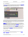
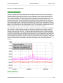
1
Orpheus
Operation Manual
by Ian Dennis
This manual is also available as 'on-line help' from the
Orpheus Control Panel applet. You can access the on-line
help from the 'Help' button in the top right-hand corner of the
applet.
Table of Contents
Part 1
General information
2
Part 2
Introduction to Orpheus
6
1
Features
................................................................................................................................. 6
2
System
.................................................................................................................................
requirements
7
3
About
.................................................................................................................................
this manual
7
Part 3
Quick start guides
1
Quick
.................................................................................................................................
start for Mac
10
2
Quick
.................................................................................................................................
start for Windows
10
Part 4
Installation procedures
1
Mac.................................................................................................................................
installation
12
2
Windows
.................................................................................................................................
installation
17
3
Cascading
.................................................................................................................................
multiple units
20
Part 5
Orpheus hardware
1
Signal
.................................................................................................................................
path architecture
22
Analogue
.......................................................................................................................................................
inputs
Overkiller
................................................................................................................................................
High-pass
................................................................................................................................................
filter
MS
................................................................................................................................................
matrix
Digital
.......................................................................................................................................................
inputs
Sample-rate
................................................................................................................................................
converter
DI................................................................................................................................................
synchronization
Analogue
.......................................................................................................................................................
outputs
Digital
.......................................................................................................................................................
outputs
Sample-rate
................................................................................................................................................
converter
Word-length
................................................................................................................................................
DO
................................................................................................................................................
synchronization
Output
.......................................................................................................................................................
mixers
Assignable
.......................................................................................................................................................
level control
Headphone
.......................................................................................................................................................
outputs
Metering
.......................................................................................................................................................
system
10
12
22
22
23
23
23
23
24
24
24
25
25
25
26
26
27
27
27
2
Synchronization
................................................................................................................................. 28
3
Front
.................................................................................................................................
panel
29
4
Rear
.................................................................................................................................
panel
30
Fuses
.......................................................................................................................................................
and ratings
31
5
Stand-alone
.................................................................................................................................
operation
31
6
Rack
.................................................................................................................................
mounting
32
Part 6
Orpheus software
1
Orpheus
.................................................................................................................................
Control Panel
34
Unit
.......................................................................................................................................................
and Global settings
34
36
Input
.......................................................................................................................................................
Setup tab
Output
.......................................................................................................................................................
Setup tab
Mixer
.......................................................................................................................................................
tabs
ADAT
.......................................................................................................................................................
tab
38
38
39
40
2
Orpheus
.................................................................................................................................
drivers
40
Part 7
Technical topics
1
Stability
.................................................................................................................................
and latency
42
2
Clocking
.................................................................................................................................
and jitter
43
3
Dither
.................................................................................................................................
and noise-shaping
45
4
Analogue
.................................................................................................................................
interconnections
48
Part 8
Specifications
54
Index
60
42
Part
1
General information
Prism Sound Orpheus
1
Operation Manual
Revision 1.05
General information
Manual revision history
Rev
1.00
1.02
1.03
1.04
1.05
Date
8th October 2007
22nd April 2008
11th August 2008
4th September 2008
20th October 2008
Author
I.G.Dennis
I.G.Dennis
I.G.Dennis
I.G.Dennis
I.G.Dennis
Notes
Product Launch
Firmware Revision 1.02
Firmware Revision 1.03
Change of addresses
Correction to fuse type
Support contacts
Prism Media Products Limited
The Old School
Stretham
Cambridge CB6 3LD
UK
Prism Media Products Inc
21 Pine Street
Rockaway
NJ 07866
USA
Telephone: +44 1353 648888
Fax: +44 1353 648867
Telephone: +1 973 983 9577
Fax: +1 973 983 9588
Email: [email protected]
Web: http://www.prismsound.com
Or contact your local Prism Sound distributor as detailed on the website.
WARNING!
TO PREVENT FIRE OR SHOCK HAZARD DO NOT EXPOSE THIS EQUIPMENT TO
RAIN OR MOISTURE. DO NOT REMOVE THE COVER. NO USER-SERVICEABLE
PARTS INSIDE. REFER SERVICING TO QUALIFIED SERVICE PERSONNEL.
© 2008 Prism Media Products Ltd
1.2
Prism Sound Orpheus
Operation Manual
Revision 1.05
Statements of conformity
This equipment has been tested and found to comply with the limits for a Class B digital device,
pursuant to Part 15 of the FCC Rules. These limits are designed to provide reasonable protection
against interference in a residential area. This device generates and uses radio frequency energy
and, if not installed and used in accordance with the instructions, may cause interference to radio or
TV reception. If this unit does cause interference to radio or TV reception, please try to correct the
interference by one or more of the following measures:
a) Reorient or relocate the receiving antenna.
b) Increase the separation between the equipment and the receiving antenna.
c) Plug the equipment into an outlet on a different circuit from the receiver.
d) If necessary, consult your dealer or an experienced radio or TV technician.
CAUTION: Changes or modifications to this equipment not expressly approved by the manufacturer
could void the user's authority to operate this equipment.
THIS DIGITAL APPARATUS MEETS ALL CLASS B LIMITS FOR RADIO NOISE EMISSIONS AS
LAID DOWN IN THE RADIO INTERFERENCE REGULATIONS OF THE CANADIAN DEPARTMENT
OF COMMUNICATIONS.
CET APPAREIL NUMÉRIQUE RESPECTE TOUTES LES EXIGIENCES APPLICABLES AUX
APPAREILS NUMÉRIQUES DE CLASSE B SUR LE BROUILLAGE RADIOELECTRIQUE EDICTE
PAR LE MINISTERE DES COMMUNICATIONS DU CANADA.
Prism Media Products Ltd hereby declares that this equipment conforms to the following standards:
EN55103-1, environment category E4
EN55103-2, environment category E4
NOTE: The use of this equipment with non-shielded interface cabling is not recommended by the
manufacturer and may result in non-compliance with one or more of the above directives. All coaxial
connections should be made using a properly screened 75R cable with the screen connected to the
outer of the connector at both ends. All analogue XLR and jack connections should use screened
cable with the screen connected to pin 1 of the XLR connector, or the jack outer, at both ends.
Trademarks
SNS, Super Noise Shaping, Overkiller and CleverClox are trademarks of Prism Media Products Ltd.
Windows, XP and Vista are trademarks of Microsoft Corporation.
Mac, OS X, and Macbook are trademarks of Apple Computer Inc.
All trademarks acknowledged.
© 2008 Prism Media Products Ltd. All rights reserved.
This manual may not be reproduced in whole or part, in any medium, without the written permission of
Prism Media Products Limited.
In accordance with our policy of continual development, features and specifications are subject to
change without notice.
© 2008 Prism Media Products Ltd
1.3
Part
2
Introduction to Orpheus
Prism Sound Orpheus
2
Operation Manual
Revision 1.05
Introduction to Orpheus
Orpheus is a FireWire multi-channel audio interface for Windows PC and Mac. As well as eight
analogue line inputs and outputs, Orpheus provides four high-quality microphone preamplifiers, two
high-impedance instrument inputs, a MIDI interface as well as a host of advanced synchronization
and monitoring facilities.
In short, Orpheus is intended to provide 'studio in a box' functionality for the digital audio workstation
(DAW) user. That's not so unusual - there are many other interfaces on the market which provide
similar functionality. However, Orpheus is unique among them in providing Prism Sound's unique
pedigree of conversion, analogue, clocking and signal processing to the DAW user for the first time in
an integrated package, with the plug-and-play convenience of an ordinary sound card.
For a more detailed summary of the features and capabilities of Orpheus, continue to the Features
section.
For directions for getting started quickly, see the Quick start guides.
For detailed hardware and software installation procedures, see the Installation procedures.
For full details of the hardware controls and connections, as well as a block diagram, look at the
Hardware section.
To learn about the control software, see the Orpheus Control Panel section.
2.1
Features
Orpheus provides eight line input channels and eight line output channels, which can be operated in
balanced or unbalanced mode, and each of which can be used with professional ('+4dBu') or
consumer ('-10dBV') signal levels. Four of the input channels have selectable microphone
preamplifiers, and two of these also have high-impedance, unbalanced instrument input jacks. 24-bit
conversion is used throughout, and sample rates up to 192kHz are supported.
Stereo digital I/O is provided in both S/PDIF and optical (TOSLINK) formats. The S/PDIF input can
also accept professional AES3 signals, and the S/PDIF output can be switched to AES3 mode if
required. The optical connectors can alternatively carry eight channels of ADAT I/O at 44.1k or
48kHz sample rates, or four channels at 88.2kHz or 96kHz.
Orpheus has a dedicated stereo analogue headphone output, with two stereo headphone jacks each
with its own level control. MIDI input and output are also provided.
Under Windows, Orpheus can be accessed by any software applications with WDM (Windows) or
ASIO capability. Under Apple OS X, Orpheus appears as a Core Audio device. Multiple Orpheus
units can be cascaded in both PC and Mac setups by daisy-chaining the FireWire connections.
To deal with low-latency requirements in live sound and over-dubbing, Orpheus has its own
fully-featured mixer for each output channel pair (including digital and headphones). When selected,
each mixer allows a low-latency mix of any input channels (as well as the output's associated
workstation feeds) to be sent to the required outputs.
A front-panel volume control can be assigned to any desired analogue or digital outputs, primarily for
© 2008 Prism Media Products Ltd
1.6
Prism Sound Orpheus
Operation Manual
Revision 1.05
use as a stereo or surround monitor level control.
2.2
System requirements
Orpheus will work with any modern host PC or Mac with a suitable operating system and FireWire
400 port. Macs (both Intel and PowerPC platforms are supported) must be running OS X 10.4 Tiger,
10.5 Leopard or later; PCs must be running Windows XP, Vista (32-bit) or later.
This is not to say that the computing power of the host is unimportant, but it is more a requirement of
the application than of Orpheus. If you need to record or playback large numbers of channel, perhaps
at high sample rates or with a lot of processing or plug-ins, you will need a host computer with a fast
processor and bus, plenty of RAM, and probably a fast hard disk too. On the other hand, playback of
moderate channel counts at lower sample rates can be accomplished with even a modest computer.
A good way to gauge this is to be guided by the system requirements of the audio software which you
are intending to use. For more information about this, see the Stability and latency section.
2.3
About this manual
The Orpheus Operation Manual is provided in two different formats: as a conventional printed
manual, and also as HTML-based 'on-line help' which can be viewed on your computer. The on-line
help version can be launched directly from the Orpheus Control Panel applet by clicking the help [?]
button in the upper right-hand corner of the panel.
The on-line version of the manual is displayed with a navigation panel to the left of the topic pages.
Links within each topic page can be clicked to navigate to pages of interest. The heading bar of each
topic page contains buttons for navigating to the previous or next topics, and for moving back to the
start of the current chapter. Alternatively, the navigation area on the left contains a "Contents" section
which shows a hierarchical map of the entire document from which desired pages can be selected
directly. The navigation area can also be used to select topics using a full keyword index, or by
searching the document for a particular word or phrase. The selection mode is switched using the
controls at the top of the navigation area.
The printed version of the manual is also provided in 'electronic' format, as a 'pdf' file, on the Orpheus
software disc. The pdf file can be viewed and printed using the Adobe Acrobat Reader, which can be
downloaded free at www.adobe.com.
Updates of both the on-line and pdf forms of the manual are available from the Prism Sound website
at www.prismsound.com.
© 2008 Prism Media Products Ltd
1.7
Part
3
Quick start guides
Prism Sound Orpheus
3
Operation Manual
Revision 1.05
Quick start guides
This section contains brief instructions to get up and running quickly. If you need more detailed
instructions, see the Installation procedures section.
3.1
Quick start for Mac
The Orpheus software can be installed on Macs with either PowerPC or Intel processors. You need a
spare FireWire 400 (IEEE1394A) port. You must have OS X 10.4 Tiger, or 10.5 Leopard, or later.
If you have Tiger, a patch must be installed before installing Orpheus - see the instructions at
the end of the full Mac installation section.
· Connect your Orpheus to the mains supply with the power-cord provided. DO NOT connect it to
the Mac yet.
· Insert the installation disc into a DVD-ROM drive on your Mac.
· Double-click on the "Install_Orpheus" package.
· Follow the on-screen instructions.
· When software installation is complete, connect the Orpheus unit to the FireWire port of the Mac.
The Orpheus device's ports should now be visible in Audio/MIDI Setup as Core Audio ports.
NOTE: Do not connect the Orpheus unit to the FireWire port of the Mac until software
installation is complete.
3.2
Quick start for Windows
To install the Orpheus software, your PC must be running Windows XP or Vista (32-bit), or later. You
need a spare FireWire 400 (IEEE1394A) port.
· Connect your Orpheus to the mains supply with the power-cord provided. DO NOT connect it to
the PC yet.
· Insert the installation disc into a DVD-ROM drive on your PC.
· If the PC is set to 'Autoplay' , installation will begin automatically, otherwise double-click on the
"setup.exe" icon in the root folder of the disc.
· Follow the on-screen instructions.
The Orpheus device's ports should now be visible to Windows and any applications as both ASIO and
a WDM audio ports, and a bidirectional MIDI port. Note that only the first two ADAT ports (if enabled
by the Orpheus Control Panel applet) are visible in the WDM case.
NOTE: Do not connect the Orpheus unit to the FireWire port of the PC until instructed to do so
during the installation process.
NOTE: Orpheus' drivers are have not been submitted for Windows Logo testing, and so
warnings of this will be issued during installation. Select 'Continue anyway' when these
occur.
© 2008 Prism Media Products Ltd
1.10
Part
4
Installation procedures
Prism Sound Orpheus
4
Operation Manual
Revision 1.05
Installation procedures
This section contains detailed installation instructions for your Orpheus. If you are keen to get going
quickly, you could use the Quick start guides section.
4.1
Mac installation
The Orpheus Control Panel applet can be installed on Macs with either PowerPC or Intel processors.
You need a spare FireWire 400 (IEEE1394A) port. You must have OS X 10.4 Tiger, or 10.5 Leopard,
or later. No driver is required, since OS X can interface to Orpheus directly.
If you have Tiger, a patch must be installed before installing Orpheus - see the instructions at
the end of this section.
The full installation procedure is as follows:
· Connect your Orpheus to the mains supply with the power-cord provided. DO NOT connect it to
the Mac yet.
· Insert the installation disc into a DVD-ROM drive on your Mac.
· If 'Autorun' is not enabled, double-click on the DVD-ROM device
· Double-click on the "Install_Orpheus" package:
· A dialogue box will guide you through the installation process; click 'Continue':
© 2008 Prism Media Products Ltd
1.12
Prism Sound Orpheus
Operation Manual
Revision 1.05
· A copy of the Orpheus EULA will appear, which you should read:
· Agree to the EULA by clicking 'Agree':
© 2008 Prism Media Products Ltd
1.13
Prism Sound Orpheus
Operation Manual
Revision 1.05
· Select a destination volume for the installation, if necessary:
· Click 'Upgrade' to perform a basic installation::
© 2008 Prism Media Products Ltd
1.14
Prism Sound Orpheus
Operation Manual
Revision 1.05
· You may need to enter an administrator's name and password. Click 'OK':
· The installation process will then complete:
· When software installation is complete, close the box and connect the Orpheus unit to the FireWire
port of the Mac.
The Orpheus device's ports should now be visible in Audio/MIDI Setup as Core Audio ports.
NOTE: Do not connect the Orpheus unit to the FireWire port of the Mac until software
installation is complete.
· Remember to register your Orpheus at http://www.prismsound.com.
OS X 10.4 Tiger patch
To ensure correct operation of Orpheus, users of OS X 10.4 Tiger must install a 'patch' before
following the Orpheus installation procedure. The patch is provided by Apple, but is not part of the
© 2008 Prism Media Products Ltd
1.15
Prism Sound Orpheus
Operation Manual
Revision 1.05
routine Tiger online update process. A copy of the patch can be found on the Orpheus installation
disc.
Before installing the patch, ensure that your Mac has been updated to at least version 10.4.11. This
should happen automatically if online updates are enabled.
Locate and double-click the following patch package on the installation disc:
AppleFWAudio-2.2.0f c9-e1.pkg
The patch will overwrite files in he directory:
/System/Library/Frameworks/FWAUserLib.framework
So be sure to back up this directory before applying the patch. In the worst case, the original files can
be restored from the OS X installation disc.
You are now ready to proceed with Orpheus installation as described above.
© 2008 Prism Media Products Ltd
1.16
Prism Sound Orpheus
4.2
Operation Manual
Revision 1.05
Windows installation
The following procedure installs the Orpheus ASIO and WDM drivers, and the Orpheus Control Panel
applet, on your Windows PC. You must have Windows XP, Vista (32-bit) or later, and a spare
FireWire 400 (IEEE1394A) port.
· Connect your Orpheus to the mains supply with the power-cord provided. DO NOT connect it to
the PC yet.
· Insert the installation disc into a DVD-ROM drive on your PC.
· If the PC is set to 'Autoplay' , installation will begin automatically, otherwise double-click on the
"setup.exe" icon in the root folder of the disc.
· A welcome screen warns you to shut down other applications prior to installation. Do so and click
'Next':
© 2008 Prism Media Products Ltd
1.17
Prism Sound Orpheus
Operation Manual
Revision 1.05
· You will be asked to agree to the Orpheus EULA - if you agree, click 'Yes':
· Choose the installation folder location by clicking 'Browse', if required, or else use the default
(recommended); click 'Next':
© 2008 Prism Media Products Ltd
1.18
Prism Sound Orpheus
Operation Manual
Revision 1.05
· Installation will then proceed:
· Orpheus' drivers are have not been submitted for Windows Logo testing, and so warnings of this
will be issued during installation. Select 'Continue anyway' when these occur:
© 2008 Prism Media Products Ltd
1.19
Prism Sound Orpheus
Operation Manual
Revision 1.05
· During installation, you will be prompted to connect the Orpheus to the FireWire port of the PC. Do
so, then click 'Next':
The Orpheus device's ports should now be visible to Windows and any applications as both ASIO and
WDM audio ports, and a bidirectional MIDI port. Note that only the first two ADAT ports (if enabled by
the Orpheus Control Panel applet) are visible in the WDM case.
· Remember to register your Orpheus at http://www.prismsound.com.
4.3
Cascading multiple units
Multiple Orpheus units can be used on the same PC or Mac by simply 'daisy-chaining' their FireWire
cables, i.e. connecting the second unit to the spare FireWire connector on the unit already connected
to the host.
The number of units which can be used successfully depends on the bandwidth of the FireWire bus,
and also on the processing power of the host computer and its audio software. The latter depends
mostly on the host's CPU and RAM fitment; for more information see the Stability and latency section.
Bus-bandwidth limitations are absolute, and apply no matter how powerful the computer is. They
depend on the sample rate:
Sample rate
44.1kHz, 48kHz
88.2kHz, 96kHz
176.4kHz, 192kHz
Maximum number of units
6
3
1
It is not recommended to mix Orpheus and other FireWire devices on the same FireWire interface.
This can lead to loss of audio channel capacity, or even loss of audio.
© 2008 Prism Media Products Ltd
1.20
Part
5
Orpheus hardware
Prism Sound Orpheus
5
Operation Manual
Revision 1.05
Orpheus hardware
This section describes in detail the capabilities of the Orpheus hardware.
5.1
Signal path architecture
The figure above is a simplified block diagram of the Orpheus audio signal paths.
Orpheus is basically a sound card, with all inputs made available to the host computer via the
FireWire bus, and all outputs likewise driven from the FireWire bus. However, Orpheus' signal paths
contain a range of enhanced processing and mixing functions, which are described in the following
sections.
5.1.1
Analogue inputs
All eight analogue input channels feature balanced line inputs on TRS jacks, with dual switchable
sensitivity to allow connection to professional or consumer line-level sources. The '+4dBu' setting
accommodates professional signals with a nominal level of +4dBu and allows a maximum level of
+18dBu (0dBFS). The '-10dBV' setting accommodates consumer signals with a nominal level of
-10dBV and allows a maximum level of +6dBu (0dBFS).Unbalanced sources are automatically
accommodated.
Input channels 1-4 also have balanced XLR microphone inputs, with gains variable from 10dB to
65dB in accurate 1dB steps, and with individually switchable phantom power.
Input channels 1 and 2 also have high-impedance front-panel unbalanced instrument jacks, also with
fine and accurate gain control.
Selection of input modes is automatic: line input mode is automatically selected on channels 1-4
whenever a TRS jack is inserted into the rear-panel combo connector, otherwise mic input mode is
selected. On channels 1 and 2, mic input mode is automatically over-ridden whenever a mono jack is
inserted in the front-panel instrument jack.
© 2008 Prism Media Products Ltd
1.22
Prism Sound Orpheus
Operation Manual
Revision 1.05
The input mode and phantom power state of channels 1-4 is indicated on the front panel of the unit,
and also in the Input Setup tab of the Orpheus Control Panel applet. Line, mic and instrument gains
are also adjusted in the Input Setup tab, as is selection of the Overkiller, high-pass filter and MS
matrix functions described in the following sections.
5.1.1.1
Overkiller
All eight input channels include a switchable Prism Sound 'Overkiller' circuit. The Overkiller is an
instantaneous progressive limiter which protects against converter overload by a margin of up to
10dB, gently absorbing transients and allowing recording levels to be raised without risk. The
Overkillers in Orpheus operate identically to those in other Prism Sound converters; they can be used
with any input mode (line, mic or instrument), and their operating thresholds are automatically
adjusted for any gain setting.
The Overkillers are switched on and off in the Input Setup tab of the Orpheus Control Panel applet. A
per-channel indication of Overkiller activity is provided both on the front panel of the unit (below each
meter, if the meters are in 'Input' mode), and also in the Input Setup tab. Note that these indicators
are dynamic, and show when the Overkiller is actually limiting.
5.1.1.2
High-pass filter
Analogue input channels 1-4 have switchable high-pass 'impact filters', which roll off below 80Hz.
These are most useful in mic input mode, in removing unwanted low-frequency content. The filters
are also available in instrument and line modes, which can be useful if, for example, external
microphone pre-amplifiers without filters are used.
The filters are switched on and off in the Input Setup tab of the Orpheus Control Panel applet.
Note that inputs 1&2 have an RIAA de-emphasis filter selectable as an alternative to the high-pass
filter, allowing them to be used with vinyl decks. The RIAA filter is aligned to have a gain of 16dB at
1kHz, so that phono cartridges fall within the sensitivity range of the instrument inputs, as described in
the vinyl decks section.
5.1.1.3
MS matrix
Analogue input channels 1-4 have switchable MS matrices. These are intended for use with
'mid-side' stereo microphones, where sum and difference signals are derived from the two input
channels creating left and right output channels. The MS matrices are also available in instrument
and line modes, allowing external microphone preamplifiers without matrixing to be used.
Note that there is no explicit stereo width control provided in the matrix; however width can be
adjusted by balancing the gains of the mid and side inputs - the gain steps of the Orpheus
microphone preamplifiers are fine and precise. In line input mode, no fine gain adjustment is
available, so if the Orpheus MS matrices are used with external preamplifiers, these must have fine
and accurate gain control if width adjustment is required.
The MS matrices are switched on and off in the Input Setup tab of the Orpheus Control Panel applet.
5.1.2
Digital inputs
RCA and TOSLINK connectors accept two-channel digital audio signals in the S/PDIF format at any
standard sample rate between 44.1kHz and 192kHz. The RCA input can also automatically accept
digital audio in the AES3 (AES/EBU) format using the XLR-RCA adapter supplied.
© 2008 Prism Media Products Ltd
1.23
Prism Sound Orpheus
Operation Manual
Revision 1.05
The Input Setup tab of the Orpheus Control Panel applet contains the control for selecting the RCA or
TOSLINK connector for S/PDIF input, and also an indicator to show that the S/PDIF input is
UNLocked (i.e. no S/PDIF carrier is recognized). The UNLock indicator is also shown beneath the
digital meter on the unit's front panel (providing that the unit's meters are in Input mode).
The TOSLINK connector can also accept 8-channel digital input in ADAT format (at 44.1kHz or 48kHz
sample rates) or 4-channel input in ADAT S/MUX format (at 88.2kHz or 96kHz sample rates).
Note that ADAT input and output is only possible when operating Orpheus in one of its specific
ADAT-capable modes. This is to reduce overhead on the host PC or Mac when ADAT input and
output is not required. For more information see the Unit Settings tab of the Orpheus Control Panel
applet.
It is possible to configure a sample-rate converter in the S/PDIF input, as described in the following
section.
5.1.2.1
Sample-rate converter
A two-channel sample-rate converter (SRC) can be activated in the S/PDIF input if desired. This
provides very high-quality conversion of any incoming digital audio signal to Orpheus' current sample
rate. The SRC is selected in the Unit Settings tab of the Orpheus Control Panel applet. Note that the
SRC can be configured in the S/PDIF input, or in the S/PDIF output, but not in both simultaneously.
Note that presence of an SRC in the S/PDIF input is shown by an indicator beneath the digital meter
on the unit's front panel (providing that the unit's meters are in Input mode).
5.1.2.2
DI synchronization
Note that it is necessary to ensure that the sample clock of any digital audio input is synchronous with
Orpheus' sample clock (unless the SRC is active in the digital input path). This can be achieved
either by synchronizing Orpheus to the source (by using DI or ADAT sync source), or by
synchronizing the source to Orpheus' S/PDIF, ADAT or Wordclock output. Orpheus also has a
Wordclock sync input for synchronization to Wordclock-equipped sources or house syncs.
The Input Settings tab of the Orpheus Control Panel applet contains an indicator to show that the
S/PDIF input is ASYNChronous (i.e. there is an S/PDIF signal present but it is not synchronous with
Orpheus' sample clock.
For more information about synchronization settings, see the Synchronization section and also the
section describing the Unit Settings tab of the Orpheus Control Panel applet.
5.1.3
Analogue outputs
Orpheus provides eight analogue output channels on TRS jacks, with dual switchable output level to
allow connection to professional or consumer line-level equipment. Connection to unbalanced
equipment is automatically accommodated by a level-compensation 'bootstrapping' circuit.
In normal operation, the eight analogue outputs are fed directly with individual signals from the host
PC or Mac; however, it is possible to feed the outputs from local digital mixers within the Orpheus
hardware if desired - this is described in the Output mixers section below.
It is also possible to assign a level control to any desired outputs, primarily for use as a monitor
volume control - this is described in the Assignable level control section below.
Setting of analogue output levels, as well as activation of output mixers and assignment of the level
© 2008 Prism Media Products Ltd
1.24
Prism Sound Orpheus
Operation Manual
Revision 1.05
control are all managed in the Outputs Setup tab of the Orpheus Control Panel applet.
5.1.4
Digital outputs
RCA and TOSLINK connectors output two-channel digital audio in the S/PDIF format at any standard
sample rate between 44.1kHz and 192kHz. The RCA output can also output digital audio in the AES3
(AES/EBU) format using the RCA-XLR adapter supplied. To do this, select 'AES3' instead of 'S/PDIF'
in the DO1/2 strip of the Outputs Setup tab of the Orpheus Control Panel applet. This causes the
carrier voltage to be increased to the AES3 level, and the Channel Status to adopt the professional
AES3 format instead of the consumer format of S/PDIF.
The TOSLINK connector can alternatively output 8-channel digital audio in ADAT format (at 44.1kHz
or 48kHz sample rates) or 4-channel audio in ADAT S/MUX format (at 88.2kHz or 96kHz sample
rates).
Note that ADAT input and output is only possible when operating Orpheus in one of its specific
ADAT-capable modes. This is to reduce overhead on the host PC or Mac when ADAT input and
output is not required. For more information see the Unit Settings tab of the Orpheus Control Panel
applet.
It is possible to perform sample-rate conversion and word-length reduction (dithering or noise-shaping
to 16-bits) as described in the following sections.
In normal operation, the S/PDIF digital outputs are fed directly with individual signals from the host PC
or Mac; however, it is possible to feed the outputs from local digital mixers within the Orpheus
hardware if desired - this is described in the Output mixers section.
It is also possible to assign a level control to the S/PDIF outputs, primarily for use as a monitor
volume control - this is described in the Assignable level control section below.
Activation of output mixers and assignment of the level control are all managed in the Outputs Setup
tab of the Orpheus Control Panel applet.
5.1.4.1
Sample-rate converter
A two-channel sample-rate converter (SRC) can be activated in the S/PDIF output if desired. This
provides very high-quality conversion of the output signal from Orpheus' current sample rate to any
standard rate between 44.1kHz and 192kHz. The SRC is selected in the Unit Settings tab of the
Orpheus Control Panel applet. Note that the SRC can be configured in the S/PDIF input, or in the
S/PDIF output, but not in both simultaneously.
When using an SRC in the S/PDIF output, it is necessary to select a synchronization source and
sample rate for the converted output. The sync source can be local, DI (the S/PDIF input) or the
Wordclock input. These settings are made in the Output Setup tab of the Orpheus Control Panel
applet.
Note that presence of an SRC in the S/PDIF output is shown by an indicator beneath the digital meter
on the unit's front panel (providing that the unit's meters are in Output mode).
5.1.4.2
Word-length
It is possible to control the word-length of the S/PDIF output using the word-length control, uppermost
in the DO1/2 strip in the Output Setup tab of the Orpheus Control Panel applet. The control operates
as follows:
© 2008 Prism Media Products Ltd
1.25
Prism Sound Orpheus
Operation Manual
Revision 1.05
Setting Action
24 bit All 24 bits sent to the digital output are transmitted from the S/PDIF or AES3 output.
Channel Status is set to indicate 24 bit output. This setting can be used to pass Dolby or
DTS data to an external decoder since it leaves the audio data from the host unchanged.
Note, however, that the use of Orpheus' local DO mixer, or the assignable level control, or
the SRC in the digital output will prevent bit-identical data from being transmitted.
16 bit Audio data sent to the digital output is re-dithered using flat TPDF dither to produce a 16 bit
output at the S/PDIF or AES3 output. Channel Status is set to indicate 16 bit output. This
setting is not generally preferable to the SNS settings, since the noise level is not
psycho-acoustically optimized.
SNS1 Audio data sent to the digital output is noise-shaped using Prism Sound's proprietary SNS
(Super Noise Shaping) process to produce a 16 bit output at the S/PDIF or AES3 output.
SNS2 Channel Status is set to indicate 16 bit output. These settings are generally preferable to
SNS3 the 16 bit setting, since the noise level is psycho-acoustically optimized. SNS1 offers the
least optimization, but with the flattest residual noise spectrum, with optimization increasing
SNS4 up to SNS4, which offers the lowest subjective noise floor, but with significant colouration
Note that if the audio data has already been word-length-processed for 16 bit output by the DAW
software, Orpheus' word-length control should be set to 24 bits to prevent unwanted additional
dithering.
For further discussion of dithering and noise shaping, and details of the SNS process, see the Dither
and noise-shaping section.
5.1.4.3
DO synchronization
Note that it is necessary to ensure that the sample clock of any digital audio device to which Orpheus'
digital outputs are connected is synchronous with Orpheus' own sample clock. This is usually
achieved by synchronizing the receiving equipment to Orpheus' S/PDIF, ADAT or Wordclock output,
but can be achieved by synchronizing Orpheus to the receiving device's clock or house sync (by
setting DI or Wordclock as Orpheus' sync source).
For more information about synchronization, see the main Synchronization section , the Clocking and
jitter section, and the section describing the Unit Settings tab of the Orpheus Control Panel applet.
5.1.5
Output mixers
Orpheus' output mixers are high-quality, versatile stereo digital mixers available at all of Orpheus'
outputs (excluding ADAT outputs). The signal processing in Orpheus' mixers is as precise and
sophisticated as in a professional digital console. All coefficients are filtered at sample-rate to
minimise unwanted quantization effects such as zipper noise.
In normal operation, Orpheus' output pairs are set in 'DAW' mode, i.e. they output their respective
feeds from the DAW software directly - in this case, Orpheus' output mixers are disabled. By
selecting 'MIX' mode for an output pair, the mixer is enabled: its inputs comprise all eight of Orpheus'
analogue inputs, the two-channel digital input, plus the respective stereo feed from the DAW
software. Each input has a dedicated fader and pan pot, plus mute and solo buttons and
high-resolution level meter. Input pairs can be designated as 'stereo', wherein a single ganged fader
and balance pot are provided, plus a single mute and solo button. The stereo output also has fader,
mute button and high-resolution level meters.
The output mixers are primarily intended to provide low-latency foldback or monitor mixes
incorporating Orpheus' audio inputs in conjunction with feeds from the DAW software - since the mix
is performed locally, the delay involved in passing live audio up to the host computer and back is
removed. However, it is also possible to configure the output mixers for general purpose use, where
inputs can be mixed to outputs without involving the Host's audio at all. Having set up such mixes
© 2008 Prism Media Products Ltd
1.26
Prism Sound Orpheus
Operation Manual
Revision 1.05
using the Orpheus Control Panel applet, it is possible to use stand-alone mode to retain the mix
features with no computer connected.
For more information, see the Mixer tabs section of the Orpheus Control Panel applet, and the
Stability and latency section.
5.1.6
Assignable level control
Orpheus' front panel has a large assignable level control. This control can be assigned individually to
any of Orpheus' analogue of digital outputs (excluding the ADAT outputs, and the headphone outputs
which have their own dedicated level controls). Operation of the front panel control fades all assigned
outputs. The setting of the control is indicated by a halo of LEDs around the knob. The assignable
level control is primarily intended to implement stereo or surround control-room monitoring systems.
Assignment is via the Output Setup tab of the Orpheus Control Panel applet. In this tab, there is also
an indication of the position of the control, which can also be operated on the screen using the
mouse.
5.1.7
Headphone outputs
The headphone outputs signal path differs from Orpheus' other output signal paths in a couple of
respects.
Firstly, the 'DAW'/'MIX' switch has a third 'BUS' position in the case of the headphones. This means
that as well as outputting the DAW headphone feeds directly ('DAW'), or outputting a mix of inputs
plus the DAW headphone feeds ('MIX'), the headphone outputs can be switched across any of the
other output pairs (except for the ADAT outputs). In the Output Setup tab of the Orpheus Control
Panel applet, just above the 'DAW'/'MIX/'BUS' selectors is a row of radio buttons for selecting which
output pair is monitored by the headphone outputs in 'BUS' mode. Note that the headphone
monitoring point of the outputs is before the application of the assignable gain control (if assigned).
Second, the headphone outputs cannot be assigned to the assignable gain control. This is because
they already have dedicated volume controls on the front panel.
5.1.8
Metering system
Orpheus' front panel meters can meter the level of either inputs or outputs as selected in the Unit
Settings tab of the Orpheus Control Panel applet. A 'Follow Global' setting is also available which
allows the input/output mode of all front panel meters in a multi-unit system to be switched
simultaneously. The left-most eight meters show the levels of the eight analogue inputs (or outputs);
the right-most two meters show the level of the S/PDIF inputs (or outputs). The bar-graphs change
colour progressively from blue, through green to orange as signal level increases. A red 'overload'
LED is lit if the signal reaches -0.05dBFS. Each of the eight analogue meters has an indicator
beneath which shows when the Overkiller (progressive limiter) is active in the case of an analogue
input.
Within the Orpheus Control Panel applet, the Input Setup tab shows the levels of the eight analogue
and two S/PDIF inputs (as per the front panel, including Overkiller indicators), and the Output Setup
tab shows the levels of the eight analogue and two S/PDIF outputs (as per the front panel) plus the
headphones level. The Mixer tabs show levels of all inputs and the stereo output of each mixer. The
ADAT tab shows the levels of all eight ADAT send and return channels.
© 2008 Prism Media Products Ltd
1.27
Prism Sound Orpheus
5.2
Operation Manual
Revision 1.05
Synchronization
This section seeks to clarify some potentially confusing issues to do with synchronization.
Sync sources, masters and slaves
A single Orpheus connected to a host computer supports a range of reference sync options:
Sync Source
Local
Wordclock
DI
ADAT
PC DAW
CSP
Master/Slave
Master
Master
Master
Master
Slave
Master
Description
System is sync'ed to Orpheus' local clock
System is sync'ed to external wordclock applied to Orpheus
System is sync'ed to external S/PDIF applied to Orpheus
System is sync'ed to external ADAT (ADAT input must be enabled)
Orpheus is slaved to system clock from host PC
System is sync'ed to Orpheus' 1394 clock (not recommended)
When multiple Orpheus units are connected to a single host, only one unit (or the host) can be
master. The remainder are slaves to the master's reference sync which is transmitted on the
FireWire bus.
Thus every port of every Orpheus in the system must operate at a common sample rate.
An exception to this is when a sample rate converter (SRC) is configured in Orpheus' digital input or
output. In the former case, the SRC simply converts any incoming digital signal of whatever sample
rate to the sample rate of the Orpheus system. But if the SRC is in the digital output, it is necessary
to specify what the output sample rate must be. Furthermore, it may be necessary to lock the output
rate to an arbitrary external reference. Orpheus allows for this; as described in the Output Setup tab
section of the Orpheus Control Panel chapter.
'Master' in the table reflects the state of the unit's front panel ''Master' indicator. If the device's is
providing the sample clock to the FireWire for the host (and any other Orpheus devices), the master
indicator is lit. If the device is receiving its sample clock from the bus, the indicator is not lit. Note
that if an Orpheus is being clocked from its wordclock or DI input, and thus is providing the clock via
the FireWire to other interfaces, it is considered to be a master.
Wordclock output
As well as outputting a clock at the selected sample rate, Orpheus' wordclock output can be
configured to produce a '256x clock' (a clock at 256x the selected sample rate, e.g. a 'superclock') or
a 'base clock' (44.1kHz if the sample rate is a 44.1kHz multiple, or 48kHz if the sample rate is a
48kHz multiple)
TAKE NOTE
It is not possible to change the sample rate in a Windows system whilst any of Orpheus' ports
are in use in WDM mode. In this case it is necessary to disconnect the ports from the
application before changing the sample rate.
In Mac OS X, the Audio MIDI Setup panel contains a drop control for selection of the desired
Sync Source. However, in versions to date, the names of the selectable Sync Sources may
not exactly match those in the Sync Source control within the Orpheus Control Panel applet.
For this reason, it is recommended that the Orpheus Control Panel applet be used for setting
the desired Sync Source.
© 2008 Prism Media Products Ltd
1.28
Prism Sound Orpheus
Operation Manual
Revision 1.05
If an external sync source such as DI or wordclock is selected, but is either absent or at a
different rate from Orpheus' selected sample rate, all audio is muted. If the reference is later
applied at the appropriate rate, audio is re-enabled.
5.3
Front panel
Orpheus' front panel contains a limited number of physical controls and indicators. A greater degree
of control is available using the Orpheus Control Panel applet software provided. The front panel also
contains the instrument input and headphone output jacks.
From left to right:
· Instrument input jacks 1&2: mono unbalanced jacks, high impedance, with finely adjustable gain
control. See Analogue inputs.
· Meter panel: see below.
· Assignable level control: Volume knob which can be assigned to any of Orpheus' analogue or
S/PDIF outputs, as required. This is primarily intended as a monitor volume control for stereo or
surround monitoring.
· Headphone jacks 1&2: each with its own volume control.
· Standby button: puts the unit into a low-power standby state. Note that the FireWire interface is still
active in standby mode, so the Orpheus unit can still be recognised by the host, although its inputs
and outputs are inactive. The LED in the standby button flashes to identify the unit in multi-unit
setups when the 'Identify' button in the Control Panel applet is clicked. Entering standby mode
causes Orpheus to retain its current software control settings in flash, for example for use in
stand-alone mode.
Meter panel
The meter panel contains metering for the eight analogue input and output channels and the two
S/PDIF input and output channels. It also contains input selection indicators for inputs 1-4, Overkiller
activity indicators for all the analogue inputs, unlock and SRC indicators for the S/PDIF input, and an
SRC indicator for the S/PDIF output.
From left to right:
· Input selection indicators: inputs 1-4 auto-select whichever type of input device is plugged in; these
indicators show the state of the selection; mic, instrument or line for inputs 1&2, mic or line for
© 2008 Prism Media Products Ltd
1.29
Prism Sound Orpheus
Operation Manual
Revision 1.05
inputs 3&4. The mic selection indicators change from green to orange to indicate that phantom
power is switched on. See Analogue inputs.
· Master indicator: this is lit when the device is sample clock master (from the FireWire bus point of
view). If a device is configured to be clock master, but is itself slaved to a wordclock or DI
reference which is absent or at a different frequency from the selected sample rate, the master
indicator flashes. For more information see the Synchronization section.
· Meter input/output indicator: shows whether the ten bar-graph meters are assigned to the analogue
and S/PDIF inputs, or to the analogue and S/PDIF outputs. This is selected in the Orpheus Control
Panel applet. See the Metering system section for more details.
· Overkiller indicators: indicate that the Overkiller progressive limiter is operating in that channel.
Note that the indication is dynamic, and shows when the Overkiller is actually limiting, and not
simply that it is enabled. Note that the Overkiller indicators are only active when the meters are in
input mode.
· DI unlock indicator: indicates that the S/PDIF input is unlocked, i.e. no S/PDIF carrier is recognised.
Only active when the meters are in input mode.
· SRC indicator: shows that the SRC (sample-rate converter) is configured in the S/PDIF input (if lit
when the meters are in input mode) or is configured in the S/PDIF output (if lit when the meters are
in output mode.
5.4
Rear panel
Orpheus' rear panel contains all Orpheus' connections, except for the instrument inputs and
headphone outputs, which are on the front panel.
From left to right (viewed from rear):
· 6A IEC inlet (regional power cord supplied): adjacent is the mains fuse holder.
· Two FireWire 400 (IEEE1394A) connectors (4-pin and 6-pin FireWire cables supplied). These
have identical function; either can be used to connect to the host computer, the other can be used
to daisy-chain additional Orpheus units if required. See Cascading multiple units.
· MIDI in and out/thru DIN sockets.
· Wordclock input and output BNC sockets: the wordclock output can supply base-clock or 256x
clock if required. See the Synchronization section.
· S/PDIF input and output RCA sockets: these can also be operated as AES3 interfaces (RCA-XLR
and XLR-RCA adapter cables supplied). See Digital inputs and Digital outputs.
· TOSLINK input and output: can be used for S/PDIF (up to 192kHz sample rate) or ADAT
(44.1kHz/48kHz or 88.2kHz/96kHz in SMUX mode). See Digital inputs and Digital outputs.
· Line output TRS jacks 1-8: switchable +4dBu/-10dBV level, can operate in balanced or unbalanced
mode. See Analogue outputs.
· Line input TRS jacks 5-8: switchable +4dBu/-10dBV level, can operate in balanced or unbalanced
mode. See Analogue inputs.
© 2008 Prism Media Products Ltd
1.30
Prism Sound Orpheus
Operation Manual
Revision 1.05
· Mic/line input combos 1-4: XLR for microphones, with 10dB to 65dB finely-adjustable gain and
switchable phantom power; TRS jack for line inputs, with switchable +4dBu/-10dBV level, can
operate in balanced or unbalanced mode. See Analogue inputs.
5.4.1
Fuses and ratings
TO PREVENT SHOCK HAZARD, THE ORPHEUS HARDWARE SHOULD ONLY BE
OPENED BY QUALIFIED PERSONNEL. REMOVE THE POWER LEAD FROM THE
UNIT BEFORE REMOVING THE TOP COVER.
Fuse locations and ratings are as follows:
FUNCTION
Mains
LOCATION
Rear panel
TYPE
500mA(T), 20mm, glass
Note that no fuses or any other user-serviceable parts or options are located inside the
Orpheus unit.
5.5
Stand-alone operation
It is possible to operate Orpheus without a FireWire connection to a host computer. This is done by
setting up the unit as required using the Orpheus Control Panel applet whilst it is connected to a host
computer via its FireWire interface, then placing the unit in standby by pressing the standby button,
before disconnecting the unit from the host and power source. When the unit is re-powered, and
detects that no FireWire connection is active, it reloads the settings which were previously stored.
Since all of the outputs have optional mixers within the Orpheus hardware whose inputs include all of
Orpheus' input connectors, it is possible, for example, to connect the digital input pair to one or more
analogue output pairs, and to mix one or more analogue input pairs to the digital output pair. The
synchronization source and sample rate can be set in the usual way. Thus stand-alone mode can be
used to configure a stand-alone D/A converter and A/D converter, with static mixing if required.
ADAT Direct mode
ADAT Direct mode allows Orpheus to operate as an eight channel analogue-to-ADAT and
ADAT-to-analogue converter. ADAT Direct mode is activated by setting the ADAT control in the Unit
Settings panel to 'Direct'.
In ADAT Direct mode it is possible to control Orpheus using the Control Panel applet in the usual way
while Orpheus is connected to a host computer via FireWire. If Orpheus is not connected to a host
computer, ADAT Direct mode can still be used as a stand-alone mode, by saving pre-selected
settings using the standby button as described above.
Signal routing in ADAT Direct mode
The eight ADAT output (send) channels are fed directly from the eight analogue input channels. Any
signals sent from the host computer over FireWire (if connected) destined for the ADAT outputs are
ignored by Orpheus.
The eight channels sent from the host computer over FireWire (if connected) destined for the
Orpheus analogue outputs are ignored by Orpheus, and replaced by the eight ADAT input (return)
channels. This means that the analogue output DAW/Mix switch can still be used: in the DAW
© 2008 Prism Media Products Ltd
1.31
Prism Sound Orpheus
Operation Manual
Revision 1.05
position, the analogue outputs are fed directly from the ADAT inputs; in the Mix position, the analogue
output mixer can be used to mix the ADAT inputs with any of the other Orpheus inputs.
The ADAT inputs and analogue inputs are available to the host computer (if connected) for recording
or monitoring if required. The ADAT outputs and analogue outputs appear to be available to the host
computer (if connected) but are ignored by Orpheus. Orpheus' S/PDIF inputs and outputs, and
headphone outputs, remain available to a connected host computer.
In common with all ADAT modes, ADAT Direct mode can only operate with all eight channels if the
sample rate is set to 44.1kHz or 48kHz. At sample rates of 88.2kHz or 96kHz, ADAT Direct mode
operates in SMUX mode, supporting only the first four analogue input and output channels. ADAT
Direct mode cannot be selected at sample rates of 176.4kHz or 192kHz.
NOTE: Since ADAT Direct mode modifies Orpheus' normal signal routing, it is very important
to ensure that ADAT Direct mode is not selected accidentally.
5.6
Rack mounting
Orpheus is supplied configured for table-top operation, with rubber feet attached and no rack-mount
ears fitted.
To convert for rack-mounting: First fit the rack-mount ears by removing the front four screws from
each side of the unit, using the hex key provided; then replace the same screws to retain the rack
ears provided. If necessary, the rubber feet can be removed by withdrawing the plastic centre-hub of
each foot a little way prior to pulling the whole foot out. The hub can be initially raised with a small
flat-bladed screwdriver. Retain the feet for later use.
If Orpheus units are rack mounted, an empty 1U gap should be left above each Orpheus to ensure
effective cooling.
© 2008 Prism Media Products Ltd
1.32
Part
6
Orpheus software
Prism Sound Orpheus
6
Operation Manual
Revision 1.05
Orpheus software
This section describes the software supplied with Orpheus.
6.1
Orpheus Control Panel
The Orpheus Control Panel applet is a program which can be used to adjust Orpheus' settings, and
view its metering and status indicators, from the screen of the Mac or PC.
Whilst Orpheus can be controlled in a limited way from within the Mac or Windows operating system,
or by some audio application programs, most of its detailed features can only be accessed using the
Orpheus Control Panel.
Accessing the Orpheus Control Panel
The Orpheus Control Panel can be run directly like any other Mac or Windows program, or it can be
accessed from the operating system itself, from the "Sound and Audio devices" dialogue in the
Windows' Control Panel (or from the Device Manager) or from the Audio MIDI Setup in Mac OS X.
Some audio applications, such as Nuendo, also allow guided access to the Orpheus Control Panel.
Operating the Orpheus Control Panel
The Orpheus Control Panel user-interface is a fixed-size dialogue box which can be activated and 'put
away' like any other Mac or Windows application. When active, it cannot be resized. The upper part
of the Control Panel contains Unit and Global settings, and beneath are a stack of 'tabs' allowing
context-switching of the bulk of the user-interface area.
The Input Setup tab contains everything to do with setting up analogue and digital inputs, the Output
Setup tab similarly for outputs. A row of Mixer tabs provide access to the low-latency built-in mixers,
whilst the ADAT tab displays meters for the ADAT inputs and outputs.
Where more than one Orpheus unit is connected, the Orpheus Control Panel controls all the
connected units. The selector at the top of the "Unit Settings" panel is used to assign the Control
Panel to whichever unit is to be controlled. If no Orpheus units are connected, the Control Panel
remains blank.
© 2008 Prism Media Products Ltd
1.34
Prism Sound Orpheus
© 2008 Prism Media Products Ltd
Operation Manual
Revision 1.05
1.35
Prism Sound Orpheus
6.1.1
Operation Manual
Revision 1.05
Unit and Global settings
The upper area of the Orpheus Control Panel contains Unit Settings and Global Settings. Unit
Settings are applied only to the Orpheus unit which the Control Panel is currently assigned to control,
whereas Global Settings apply to all connected Orpheus units as a whole.
The upper area also contains buttons for loading and saving Orpheus configurations, and for
accessing the on-line help.
Unit Settings
The topmost control in the Unit Settings panel is the Unit Selector. This selects which Orpheus unit
is controlled by the rest of the Unit Settings panel, and by the tabbed panels in the lower part of the
Control Panel (the Global Settings panel controls all connected units, and is the only part of the
Control Panel not affected by the Unit Selector). The Unit Selector is a drop-list which can be
dropped by clicking the down-arrow at the right-hand-side, presenting a list of all the connected
devices for selection. The name of the selected device is then displayed, along with the device type
(e.g. Orpheus, in the high-lit area on the right).
By default, the name of each device is its GUID (Globally Unique Identification number), but this can
be changed to a more friendly name (Windows only) by clicking in the left-hand side of the selector
and typing in a new name. This doesn't change the unit's GUID, of course - it only associates a
friendly name with the GUID whenever the OS or Control Panel applet sees the unit.
Below the Unit Selector is the Identify button. This can be latched on or off by clicking it. When it's
on (high-lit red) the LED in the standby switch of the currently-selected unit flashes. This helps to
identify each unit in a multi-unit system.
The Sync Source control allows each unit's reference synchronization source to be selected. For
more details, see the Synchronization section.
NOTE: If an external sync source such as DI or wordclock is selected, but is either absent or
at a different rate from the selected sample rate, all audio is muted. If the reference is later
applied at the appropriate rate, audio is re-enabled.
The FP Meters control allows the front panel meters to be switched between the analogue and
S/PDIF inputs, and the analogue and S/PDIF outputs. An additional selection, 'Follow Global', allows
multiple units' meters to be switched using a single control in the Global Settings. For more
information, see the Metering system description. Note that right-clicking on the FP Meters control
(control-clicking on one-button Macs) brings up a brightness control for the Orpheus front panel - four
different brightness settings can be selected to suit ambient lighting conditions.
The Clock Out control can be used to cause the unit's wordclock output to produce base clock or
256x clock instead of wordclock if required. For more details, see the Synchronization section.
A two-channel sample-rate converter (SRC) can be configured in the S/PDIF input path, or in the
S/PDIF output path, or can be disabled, using the SRC control.
ADAT inputs, or ADAT outputs, or both, can be enabled using the ADAT control. By default, ADAT
ports are disabled to ease load on the host computer. ADAT Direct mode is a special mode which
© 2008 Prism Media Products Ltd
1.36
Prism Sound Orpheus
Operation Manual
Revision 1.05
allows Orpheus to operate as an eight channel analogue-to-ADAT and ADAT-to-analogue converter,
as described in the Stand-alone operation section.
NOTE: Changing the ADAT mode causes changes in the number of input and output channels
reported to the host computer by Orpheus. It is therefore advisable to close your DAW
application before changing the ADAT mode, and to restart it again afterwards, in order to
ensure reliable operation.
Global Settings
The Global Settings panel contains a small number of controls which apply to all units in a multi-unit
system.
Most important is the Sample Rate control. All units in a multi-unit system must operate at a
common rate. For further information about sample rates, see the Synchronization section.
NOTE: It is not possible to change the sample rate in a Windows system whilst any of
Orpheus' ports are in use in WDM mode. In this case it is necessary to disconnect the ports
from the application before changing the sample rate.
The FP Meters control allows I/O switching of front panel meters across multiple boxes as described
above.
In Windows systems, the audio delay through the input and output buffers can be controlled with the
Buffer Time and Latency controls. The Buffer Time control sets the duration of a buffer, and the
Latency control sets the overall path delay by applying a number of such buffers to the audio path. In
general, it is better to keep the Latency in general, and the Buffer Time in particular, quite long. This
reduces the risk of audio glitches, as described in the Stability and latency section. Orpheus'
low-latency on-board foldback mixing facility reduces the need for the Latency controls to be short. In
Mac systems, latency control is handled by OS X.
Load, Save and Help buttons
The green Help button ('?') opens the online version of this manual in a browser window.
The red Save and the orange Load buttons save and load Orpheus settings to and from disk. Note
that only settings of the currently-selected unit are affected, so it is necessary to save and load
settings of each unit individually in multi-unit systems.
© 2008 Prism Media Products Ltd
1.37
Prism Sound Orpheus
6.1.2
Operation Manual
Revision 1.05
Input Setup tab
The Input Setup tab contains the controls and status indicators for all functions of the analogue inputs
and S/PDIF inputs as described in the hardware section. Inputs 5-8 handle line-level inputs, whereas
inputs 3&4 can operate as mic or line inputs, and inputs 1&2 as instrument, mic or line. Mode
selection is handled automatically depending on which connectors are used.
Instrument input mode is indicated by the blue 'INST' legend at the top of the strip, microphone mode
by the pink 'MIC' legend and line mode by the green 'LINE' legend. Line input sensitivity is switched
between +4dBu and -10dBV nominal by the '+4/-10' radio buttons, whereas mic and instrument input
gains are adjusted in 1dB steps by the slider controls, and indicated by the number beneath, which
can also be directly entered if required.
Overkiller progressive limiters are selectable for each analogue input, with phase-reverse and
high-pass filters being available for mic and instrument inputs. Mic inputs have +48V phantom power
switchable per-channel. Inputs 1&2 have an RIAA de-emphasis filter selectable as an alternative to
the high-pass filter, allowing them to be used with vinyl decks. MS matrixing is available for mic or line
inputs 1-4, allowing use of mid-side microphone configurations.
The DI strip can be switched between RCA and TOSLINK S/PDIF inputs, and UNLock and ASNC
indicators are provided. UNLock is lit when no S/PDIF carrier is detected at the selected input; ASNC
(asynchronous) is lit when the incoming carrier is not locked to Orpheus' selected sync source.
All inputs have high-resolution peak metering, with overload indication 0.05dB below clipping; the
analogue input meters also have Overkiller-active indicators which light dynamically when the
Overkillers are limiting.
6.1.3
Output Setup tab
The Input Setup tab contains the controls and status indicators for all functions of the analogue
outputs and S/PDIF outputs as described in the hardware section.
© 2008 Prism Media Products Ltd
1.38
Prism Sound Orpheus
Operation Manual
Revision 1.05
Line output level is switched between +4dBu and -10dBV nominal by the '+4/-10' radio buttons.
The stereo digital output has a versatile word-length control using TPDF dither or Prism Sound SNS
(Super Noise Shaping), and the RCA connector can be switched to operate as either S/PDIF or AES3
as required. If the sample rate converter (SRC) is configured in the digital output, a separate sync
source and sample rate can be selected.
An assignable level control is available, for use as a stereo or surround monitor volume control, which
can be assigned to any desired outputs using the row of 'VOL' buttons. The volume control can be
adjusted using the mouse, as well as with the front-panel knob. There is also a mute button and a
numerical readout/setting box. Note that changes to the assignment of the level control can be
prevented by engaging the lock button (marked with a key symbol) just above the level control. When
engaged (red) the lock button prevents changes to the level control assignment in order to avoid
accidental full-level output.
Below each stereo output strip is a drop-list control allowing each output pair to be fed either directly
from the workstation ('DAW') or from a dedicated low-latency foldback mixer ('Mixer'). Each stereo
mixer can mix any of Orpheus' analogue or digital inputs to the output pair, along with the DAW feed,
as described in the following section. The headphone output pair has a third 'Bus' setting which
allows it to monitor any of the other output pairs using the row of headphone bus radio buttons.
All outputs have high-resolution peak metering, with overload indication 0.05dB below clipping.
6.1.4
Mixer tabs
The Mixer tabs control the low-latency foldback mixers which are available for each analogue output
pair, plus the stereo digital and headphone outputs. The mixers are enabled using the drop-list
controls on the Output Setup tab, which are duplicated in the output strip of each respective mixer.
© 2008 Prism Media Products Ltd
1.39
Prism Sound Orpheus
Operation Manual
Revision 1.05
Each input channel has a fader, a high-resolution peak meter, with overload indication 0.05dB below
clipping, plus mute and solo buttons and a pan-pot. By engaging the 'Stereo' button beneath an input
pair, the pair is controlled by a single stereo fader, mute button and solo button, and the pan-pots are
replaced by a single balance control. The DAW contribution and output strip are always in stereo
mode.
Note that if the mixer tab is not active (because the output pair is in 'DAW' mode), the mixer controls
are still available but the output mode control in th output strip is highlighted in red.
For more information, see Output mixers in the hardware section.
6.1.5
ADAT tab
The ADAT tab contains eight high-resolution peak meters for the ADAT inputs and outputs. The
meter bank is assigned to the ADAT outputs by selecting 'Send' or to the ADAT inputs by selecting
'Return'
6.2
Orpheus drivers
For Windows systems, Orpheus is supplied with a driver which provides ASIO and WDM connectivity
to the device. This driver is installed when the initial installation is performed. Thereafter, this
connectivity is permanently available. It is not necessary to run the Orpheus Control Panel applet for
applications to be able to use Orpheus; however, the applet is needed if any but the most basic
control of Orpheus' functions is required.
The same is true in Mac systems, except that no driver is installed because OS X is able to operate
Orpheus directly to obtain basic Core Audio functionality. However, whilst some degree of control is
possible from the Mac's Audio MIDI Setup, the Orpheus Control Panel applet must still be run to
control the majority of the unit's functions.
© 2008 Prism Media Products Ltd
1.40
Part
7
Technical topics
Prism Sound Orpheus
7
Operation Manual
Revision 1.05
Technical topics
The following sections contain detailed discussions of various relevant technical issues. The content
of these sections is not required to operate Orpheus, but is provided merely as background
information.
7.1
Stability and latency
Since audio production has found its way inside the computer, new problems concerning issues of
stability and latency have arisen.
Pre-computer digital audio gear introduced the concept of delays through devices, which hadn't
usually been the case with analogue equipment. This was an inevitable consequence of sampling the
audio, and passing the samples through multiple layers of buffering during conversion, processing
and interfacing operations. However, the 'latency' (buffer delay) was generally quite short and didn't
usually cause problems even in delay-sensitive applications such as live sound or over-dubbing.
Reliable operation was generally guaranteed, since the digital devices were essentially 'sausage
machines' performing nothing but the same limited series of operations repeatedly.
When general-purpose computers began to be used for audio production, problems with latency and
stability suddenly had to be addressed. The reason is that computers are always busy doing other
things than processing audio, even in situations where the operator is only interested in performing
that dedicated task. Because of this, the computer generally accumulates a large buffer of incoming
audio samples, which are then processed whilst a new buffer is being collected. Even though the
required processing can (hopefully) be accomplished faster than real-time (i.e. the sample
processing rate is faster than the sample rate), there is always the possibility that the computer may
be called upon to interrupt its processing of the audio in order to deal with some other essential
routine task, such as maintaining screen graphics, moving data on and off disc, servicing other
programs etc. In non-optimized systems, tasks such as collecting emails, virus-checking and
countless low-importance system operations can interrupt audio processing. Without the
accumulation of sample buffers, any interruption taking longer than about one sample period (1/fs)
would cause incoming audio samples to be missed, resulting in disruption of the audio signal. Nearly
every kind of interruption is long enough to do this. However, with a large enough buffer, the
interruptions don't cause audio to be disrupted so long as the computer has enough time available
during the buffer period to process the entire buffer. This problem doesn't only happen for incoming
samples: audio outputs from the computer must likewise be buffered so that a continuous output
stream can be maintained even when the processor is called away for a while.
Why is this a problem? First of all, the amount of latency required in order for a particular computer
with a particular audio processing and non-audio workload not to suffer audio disruptions can be
problematically large. This is particularly the case in live sound and over-dubbing situations where the
delay between the computer's input and output has to be essentially imperceptible. This is often
difficult or impossible to achieve, unless the computer has a powerful processor, a lot of memory, a
heavily audio-optimized operating system workload, an efficiently written audio processing program,
and not too many audio channels, not too much audio processing complexity, and not too high a
sample rate. The operator merely has to make sure that all these conditions are met, and all will be
well!
But how do you do that? Even if we worry only about the computer and operating system themselves,
the duration and frequency of interruptions is very non-deterministic: something can happen very
infrequently which causes a huge interruption. This might not be a problem: you can always run that
track again (assuming you noticed the glitch) - but what if you're recording an important one-off live
event? Even worse, the onset of trouble is greatly affected by audio factors such as number of
tracks, sample rate, how many EQs are in use, etc. This makes the onset of instability even harder to
predict reliably.
On the other hand, situations where latency is critical are relatively few, so it is normally OK to operate
generous buffers - such as in the live recording example.
© 2008 Prism Media Products Ltd
1.42
Prism Sound Orpheus
Operation Manual
Revision 1.05
In the case of Orpheus, problems of latency and stability are improved by a couple of useful features:
First of all, the operator can control the buffer delays within the Mac and Windows drivers directly,
irrespective of what buffering is employed by the user's particular audio software. It is generally
recommended that these buffer delays are set long, in order to provide best stability. However, for
the user with a powerful and tightly-optimized setup, who has contained audio processing task and
needs low latency, the buffer delay can be minimized. For more information, see the Unit and Global
settings section..
For foldback and over-dubbing situations, all of Orpheus' outputs (analogue 1-8, S/PDIF DO, and
headphone outputs) have a comprehensive mixer capability which can mix any of the unit's inputs
with each output's computer feed in order to build a dedicated monitor mix with extremely low
latency. Incoming audio to the mix doesn't have to go in and out of the computer at all - the mix is
handled within the Orpheus hardware itself. For more information, see the Output Setup tab and
Mixer tabs sections.
7.2
Clocking and jitter
Good clock stability is probably the single most important issue separating good-quality analogue
interfaces from the rest. With the linearity of modern A/D and D/A converter chips beginning to rival
and exceed the performance of the best analogue circuits, digital recordings would already be ‘
beyond reproach’ if clock stability did not so often degrade their potential quality.
Why is good clock stability so rare? Probably because most conversion equipment has to
compromise between clock stability, operational requirements and cost. The ideal clock system in an
A/D or D/A converter would be ultimately stable, i.e. would exhibit no jitter (frequency variations) at the
point of conversion, whether operating from an internal clock or from an external synchronization
reference of any format and at any sample rate. But this is a very tall order for circuit designers,
especially if they are on a budget.
Why are good clocks so rare?
Most analogue interfaces can provide workmanlike performance when internally clocked, since this is
only a matter of providing a stable clock oscillator (or range of oscillators) at a fixed frequency (or
frequencies) – although even this is not always well-executed. The real problem is that in many
installations the analogue interfaces can almost never operate from their own internal clocks since
they must be slaved to an external reference sync, or maybe to a clock from a host computer.
The externally-clocked design challenge has traditionally been a trade-off. since the more stable a
clock oscillator is, the less is its range of frequency adjustment: but we would ideally like an oscillator
which can operate over a wide range of sample rates, perhaps from <44.1kHz to >48kHz, plus
multiples thereof. But such an oscillator would inevitably have poor stability – at least in terms of the
stringent requirements for high-quality audio conversion. On the other hand, if we limit the range of
rates at which the oscillator needs to operate to small ‘islands’ around the standard sample rates we
could use a bank of oscillators, selecting the appropriate oscillator according to our desired sample
rate. But this is expensive and, in any case, the 'pull-range' of an ordinary quartz crystal oscillator is
still generally insufficient to meet the tolerance demands of the digital audio interfacing standards.
As well as a very stable clock oscillator, a good sounding converter must have a PLL (phase-locked
loop) with a loop-filter which steeply attenuates incoming reference jitter towards higher frequencies.
Unfortunately, even if sourcing equipment provides a reference clock with low jitter, cabling always
adds unacceptable amounts, especially poor quality or high-capacitance cable, which results directly
in sampling jitter in the analogue interface if jitter-filtering is inadequate.
Prism Sound's unique CleverClox technology breaks these traditional constraints, allowing a low jitter
clock to be re-created from any reference sync, no matter how much jitter it has and no matter what
its frequency.
© 2008 Prism Media Products Ltd
1.43
Prism Sound Orpheus
Operation Manual
Revision 1.05
But why is clock jitter so important?
Analysis of sampling jitter
Analysis of sampling jitter (small variations in the sampling intervals of an A/D or D/A converter)
shows that it produces a similar effect to phase modulation, where distortion components appear as ‘
sidebands’ spaced away from the frequency of a converted tone by the frequency of the jitter itself.
These components get louder as the amount of jitter increases, but also as the frequency of the
converted tone increases. So sampling jitter produces distortions which should sound much worse
than conventional analogue harmonic distortions, since the spurious components appear at
aharmonic frequencies. High audio frequencies should suffer worse distortion than low frequencies.
For low-frequency jitter, the resulting distortion sidebands appear close in frequency to the audio
signals which produce them – this should mean that they are ‘masked’ from our hearing by the same
psycho-acoustic phenomenon upon which are based sub-band (perceptual) coding schemes such as
MPEG. This is fortunate, since it is quite difficult for a PLL to remove jitter to a good degree even at
moderate frequencies, but for very low frequencies it would be very difficult indeed.
The graph below shows the effects of 'JTEST', a special test stimulus to expose jitter susceptibility of
D/A converters. JTEST is basically an fs/4 tone (12kHz at fs=48kHz) which is specially coded to
cause an AES3 or S/PDIF carrier transmitted over a lossy cable to become very jittery by the time it
reaches the receiving D/A converter. The jitter produced has regular frequency components fs/96
apart (500Hz at fs=48kHz). The quality of the D/A converter's jitter rejection is shown by the degree
to which it suppresses the resulting 500Hz-spaced side-tones. In the example below, the upper trace
shows the poor jitter rejection of 'conventional' D/A converter design, where the conversion clock is
derived directly from the AES3 or S/PDIF receiving chip, without any further jitter filtering. Remember
that none of these side-tones is present in the digital audio signal - they are caused only by jitter. The
lower trace shows almost complete jitter rejection across the band by the CleverClox process in
Orpheus.
Listening experience
© 2008 Prism Media Products Ltd
1.44
Prism Sound Orpheus
Operation Manual
Revision 1.05
In practice, it seems that the benefits of careful clock design are very apparent in listening tests. On
the other hand, it can sometimes be difficult to expose the shortcomings of converters with poor
clocks, because these units often have other analogue problems whose severity might obscure
jitter-related effects.
In general, some of the widely-noted effects of sampling jitter are not surprising – for example the
muddying of brass, strings and high-frequency percussion and the loss of stereo (or multi-channel)
imaging. These are well explained by the worse distortions which result in the lab at loud, high
frequencies, and the way that sampling jitter produces quiet, aharmonic components, perhaps only
subliminally perceptible, which blur our impression of the ambience which creates a soundstage.
Other effects are harder to explain – for example there is wide observation that large amounts of
sampling jitter can take the edge off extreme bass rendition. Such reports are probably too
widespread to be ignored, but defy explanation within current theory.
Orpheus and CleverClox
Orpheus is designed to source clocks which are as stable and accurate as possible, and also with the
aim of being insensitive to the quality of incoming clocks. It is designed to remove jitter from any
selected reference sync source before it is used as a conversion timebase, so as to eliminate any
audible effects of sampling jitter, whatever sync source is used.
Orpheus does this with the help of Prism Sound's unique CleverClox clock technology, which
removes the jitter from any selected clock source down to sub-sonic frequencies, without the need for
a narrow-band quartz VCO. CleverClox can adapt to any reference, irrespective of frequency, and
regardless of how much jitter it has, derives an ultra-stable conversion timebase.
7.3
Dither and noise-shaping
Orpheus can dither or noise-shape its digital output to produce high-quality 16 bit output (for, say, a
CD master) from 20 bit or 24 bit recordings. This section discusses the principles and choices
involved in word-length reduction.
Truncation and dithering
There are many points in a digital audio signal path where precision can be lost. For example, in a
digital transfer from 24-bits to 16-bits, or in an analogue to digital conversion. In this situation it is not
sufficient just to discard low-order bits – this causes truncation distortion, characterised by aharmonic
frequency components and unnatural, harsh decays.
Instead, it is preferable to use some sort of ‘dithering’ process, whereby the truncation process is
linearized by modulating the signal prior to the truncation, usually by the addition of a small amount of
noise. By adding a random element to the truncation decision, small components as far as 30dB
below the noise floor can be accurately represented, and an analogue-like low-signal performance
can be realised. This is achieved at the expense of slightly raising of the noise floor, although with
some dithering schemes such as noise-shaping, linearization can be achieved with no noticeable
increase in noise.
How can dithering allow information to be preserved below the least-significant bit? It seems
impossible. Consider a simple example where the audio samples are numbers between one and six,
and we are going to ‘truncate’ them (i.e. reduce their resolution) so that numbers from one to three
become zero, and those from four to six become one. Clearly much information will be lost, and all
excursions of the signal between one and three and between four and six will not affect the output at
all. But if we throw a die for each sample, add the number of spots to that sample, and translate
totals of six and below to zero and totals of seven and above to one, we have a simple dithering
scheme. Input samples of three will be more likely to result in outputs of one than will inputs of one.
The throw of the die is our dither noise. Since all the faces of the die have an equal chance of
© 2008 Prism Media Products Ltd
1.45
Prism Sound Orpheus
Operation Manual
Revision 1.05
occurring, this is known as ‘rectangular probability distribution function’ (RPDF) dither, which in fact
does not produce perfect linearization. We actually use ‘triangular probability distribution function’
(TPDF) dither, which is like throwing two dice with a resultant increase in the probability of medium
sized numbers – totals of two and twelve occur much less often than seven.
Noise shaping
It is possible to reduce the subjective effect of the added dither noise by either using spectrally
weighted ('‘blue'’) dither noise, which is quieter in the more sensitive registers of the ear, or by an
even more effective technique called ‘noise shaping’.
Noise shaping is just like conventional dithering, except that the error signal generated when the
unwanted low-order bits are discarded is filtered and subtracted from the input signal. You can’t get
something for nothing – the error cannot be simply cancelled out, because we already know that the
output hasn’t got enough bits to precisely represent the input. But by choosing an appropriate shape
for the error filter, we can force the dither noise / error signal to adopt the desired shape in the
frequency domain – we usually choose a shape which tracks the low-field perception threshold of the
human ear against frequency. As can be seen from the plots below, this has the effect of actually
lowering the noise floor in the more sensitive frequency bands when compared to the flat dither case.
The theory of noise shaping has been around for a long time – certainly since well before DSP in
real-time was feasible for audio signals. It has applications in many signal processing and data
conversion applications outside audio. It has been well researched, and is not in the least bit
mysterious. ‘Proprietary’ word-length reduction algorithms are generally conventional noise shapers.
Assuming that the basic implementation and dither levels are correct, the only significant freedoms
available to the designer are to choose the actual shape of the noise floor, and to decide how to adapt
this (if at all) to different sample rates.
Prism Sound SNS (Super Noise Shaping)
Orpheus provides a comprehensive choice of dithering and noise-shaping processes. These
comprise ‘flat’ dithering, plus a selection of four Prism Sound ‘SNS’ (‘Super Noise Shaping’)
algorithms. All produce high-quality 16 bit output: the choice of which one to use is purely subjective.
The four SNS algorithms are designated SNS1 to SNS4, in increasing order of the degree of shaping.
The spectra of the four SNS algorithms are shown below. Note that, unlike some noise shaping
algorithms, SNS spectra are adjusted automatically to provide optimum subjective advantage at each
different sample rate. The spectra are shown below for 16-bit output, at 44.1kHz, 48kHz and 96kHz
sample rates.
SNS1 provides the smallest subjective noise advantage, but only applies limited
noise-lift at quite high frequencies. In many applications, particularly those where
the program material is already quite noisy, this type of shaper is preferred.
SNS2 is a happy medium. It provides a good amount of subjective lowering of the
noise floor, but with addition of only moderate amounts of high-frequency noise. It
also has the advantage that the noise floor remains subjectively white, even when
artificially amplified. In the fifteen years since Prism Sound first developed the four
SNS curves, SNS2 has been the most widely preferred.
SNS3 and SNS4 are ‘optimal’ shaper designs – their shaping is quite extreme in
order to get the maximum theoretical subjective improvement in noise
performance based on an average human low-field sensitivity curve. This results
in the addition of larger amounts of high-frequency noise. These shapers are only
really useful if the original recording has a very low noise floor.
It is difficult to assess the difference in sound between different noise shapers for any given program
material, since their effects are at very low amplitudes (the 0dB line on the plots below represents flat
dither with an rms noise amplitude of about –93.4dBFS). It is tempting to audition noise shapers by
using a low signal level and boosting the shaper output by tens of dBs in the digital domain prior to
monitoring. Using this method it is easy to hear that the noise floor of more extreme shapers is
© 2008 Prism Media Products Ltd
1.46
Prism Sound Orpheus
Operation Manual
Revision 1.05
clearly not white – switching, say, from SNS1 to SNS4 sounds like shhhhh..ssssss as the noise is
shifted towards the higher frequencies. However, this is not really a meaningful test since the
sensitivity of the ear at different frequencies is very dependent on level, and the design of the more
extreme shapers is in any case intended to render the noise floor completely inaudible at normal
listening levels. Ultimately, the only ‘right’ choice of noise shaper is the one which sounds best for the
material. SNS2 is a good starting point for most situations.
The Prism Sound SNS logo shown above is found on many of the world’s finest CDs, and is
recognised as a standard of technical excellence. The logo, and accompanying sleeve note, is
available by contacting [email protected].
© 2008 Prism Media Products Ltd
1.47
Prism Sound Orpheus
7.4
Operation Manual
Revision 1.05
Analogue interconnections
To maintain the high sound quality of Orpheus, it is important to follow some basic guidelines when
making analogue connections to the unit. This section discusses some things to watch out for.
© 2008 Prism Media Products Ltd
1.48
Prism Sound Orpheus
Operation Manual
Revision 1.05
Cable quality
Use of good-quality, heavy duty audio cables is recommended. For microphone use, quad-twisted
cables may give best results. Cables with heavy screens are recommended, especially for
unbalanced use. Owing to mechanical differences between connectors from different manufacturers,
it is advised to use cables with identifiable connectors from reputable manufacturers. This is
especially true for jacks, where unreliable tip connection can owing to the slightly non-conforming
shape of some manufacturers' parts. Neutrik connectors are used in Orpheus, and these are
recommended to ensure reliably-mating cables.
Balanced versus unbalanced connections
Where possible, balanced interconnections should be used, since the audio signal is represented as
a voltage difference between two dedicated conductors (neither of which is ground-coupled), which
are usually closely-twisted to ensure that any interference pickup is cancelled out. In unbalanced
connections, the signal is represented as a voltage difference between a single signal conductor and
an accompanying ground conductor. Where dynamic ground-potential differences exist between the
source equipment and the receiving equipment, this difference is effectively added to the unbalanced
audio signal.
This effect has long been familiar in audio systems as 'hum loops', where the variation in ground
potential occurred at line-frequency, and was developed by the flow of line-frequency currents to
linear power supplies. Hum loops were usually resolved by either steering the currents along
non-critical routes by re-arranging the topology of the system ground interconnections, or by
mass-interconnection the system grounds using heavy gauge cable so as to minimize the hum
voltage resulting from the current.
Obviously many items of analogue audio equipment only have unbalanced connections; this is
especially true of consumer equipment, which is often used for monitoring even in professional
studios. If you must use unbalanced connections, keep them as short as possible and use
good-quality cables with substantial screens. If you have a choice, keep the signal level as high as
possible on the interconnection, since this will make any interference proportionally less noticeable.
Instrument connections are often particularly vulnerable to hum and other interference, since they are
usually unbalanced and low-level, and frequently employ a long cable not selected for its
interference-immunity qualities. Also, the source impedance is usually high, making the connection
particularly vulnerable to interference.
Some digital audio and computer equipment with switched-mode power supplies can cause
particularly troublesome interference problems, especially for low-level, unbalanced signals. This is
discussed in the following section.
Interference
The increasing use of low-cost digital equipment and computers in the audio production process
results in various potential problems for the remaining analogue devices. It is well-known that the
hostile power and EMC environment inside a typical computer is likely to be the limiting factor
governing the audio quality of an internal analogue sound card. A solution to this is the use of external
'sound cards', such as Orpheus, with their own enclosures and power supplies allowing adequate
space, power and electromagnetic peace and quiet for the well-being of studio-quality analogue
circuits.
However, even the sound quality of external devices can be compromised by the proximity of some
types of digital equipment. Many low-cost switched-mode power supplies emit interference which can
compromise system audio quality even at a distance. The hostile mechanism is usually 'conducted
interference', wherein the high-speed switching action of the power converter results in voltage and
current transients being conducted back down their power cords. If the equipment is connected to
mains safety-ground, transients can also be conducted down the ground connection. Radiated
© 2008 Prism Media Products Ltd
1.49
Prism Sound Orpheus
Operation Manual
Revision 1.05
emissions (airborne radio interference) can also be a problem, but it is less common that this will
have such a serious effect on audio quality.
Conducted power-line interference can cause problems in analogue equipment within the installation
if its own power supply allows the transients to pass through to the audio circuits. However,
conducted ground interference can be even worse since, if the ground connection of the analogue
equipment is modulated by switching interference, there is nothing that the designer of the equipment
can do to combat it.
How much any conducted ground interference affects audio quality depends on many factors, mostly
to do with how the various analogue boxes in the system are interconnected and grounded. Where
possible, high-level balanced connections should be used, just as in the case of hum-loops as
discussed in the previous section.
Where ground-potential variations are caused by switching power supplies, the effect can be more
difficult to resolve, since the signals can occur at more noticeable frequencies: although the supplies
usually switch at frequencies too high to hear, the frequency is often modulated by variations in the
load current over time, resulting in a continuous modem-like chirping in which can be heard particular
events such as computer screen updates, disk activity etc.). Another problem is that even heavy
ground cabling may not reduce the effect of the interference, since high-frequency currents may not
see much less resistance in a thick conductor than a thin one.
How do the equipment manufacturers get away with this? Surely there are stringent regulations
covering conducted and radiated emissions? Well that's true, but the level of emissions which can
result in audible degradation of low-level, unbalanced audio interconnections are well below
legislation levels. Unfortunately, computer power supplies (and especially the switching wall-warts
and line-warts which power notebook computers and other small items) are amongst the worst
offenders.
Vinyl decks
Orpheus is equipped with an RIAA de-emphasis filter to allow direct connection of a vinyl deck, as
described in the Analogue inputs section. Since vinyl decks usually have a low-level, unbalanced
output it is important to minimise interference as discussed above when connection a vinyl deck.
Since most magnetic cartridges require a higher input impedance than that of the Orpheus
microphone preamplifier input, it is usually best to connect a vinyl deck to the instrument inputs using
a pair of phono-to-mono-jack cables. The instrument gain controls can then be set to an appropriate
level for the particular cartridge. The 1MR input impedance of the instrument inputs will work
satisfactorily with most magnetic phono cartridges (which are 'moving magnet' types), but with some
cartridges, improved frequency response and noise levels can be achieved by fitting the cartridge's
required load resistance (usually 22kR or 47kR) across the instrument input terminals; this is best
achieved by soldering it inside the jack. Moving coil cartridges have a lower output level and require a
lower preamplifier input impedance. These are best connected to Orpheus' mic inputs, or may
require a dedicated preamplifier.
Most vinyl decks have a ground wire separate from the audio connectors. Connection of this wire for
lowest hum is often a matter of trial and error. Ideally this should be connected to Orpheus' analogue
signal ground (the outer of the instrument input jacks, or pin 1 of the mic input XLRs). Since no
dedicated terminal exists on Orpheus, it is usually easiest to connect the wire to the outer of one of
the deck's unbalanced output connectors. In some situations, a direct connection to local mains
ground may work better.
In summary
· Use good-quality cables with reputable connectors;
· Use balanced connections where possible; if you must use unbalanced connections, keep them
short;
© 2008 Prism Media Products Ltd
1.50
Prism Sound Orpheus
Operation Manual
Revision 1.05
· Ensure that signals passing between equipment do so at as high a level as is practical;
· If switching interference is heard, try to identify the source equipment by unplugging things one by
one. When you find the culprit, either re-plug it a long way from the audio equipment, or use a
power filter, or both.
© 2008 Prism Media Products Ltd
1.51
Part
8
Specifications
Prism Sound Orpheus
8
Operation Manual
Revision 1.05
Specifications
Front Panel
Instrument inputs 1&2:
Two 6.3mm mono jack sockets, auto-select to analog inputs 1&2 when
plugged
Headphone outputs 1&2: Two 6.3mm stereo jack sockets, each with illuminated volume control
Master volume control: Assignable to any selection of outputs, with LED halo indication
Multi-segment, multi-color bargraphs with overload indication; eight for
Level meters:
analog, two for digital, assignable to inputs or outputs
Input selector indicators: Indicate modes of analog inputs 1-4 as mic/line/instrument; plus phantom
power indicator for mic mode
For every analog input, lit when Overkiller limiters are acting
Overkiller-active
indicators:
Digital input indicators: Input unlocked, and SRC (sample-rate converter) selected
Digital output indicator: SRC (sample-rate converter) selected
Master, lit when interface is providing system sync
Sync indicator:
With standby indicator (also flashes when unit is in 'identify' mode)
Standby button:
Rear Panel
Mic/Line inputs 1-4:
Line inputs 5-8:
Line outputs 1-8:
Digital inputs:
Digital outputs:
MIDI I/O:
Wordclock I/O:
FireWire ports:
Mains power:
Software Support
Mac OS support:
Windows OS support:
Mac audio driver:
Windows audio driver:
Control Panel applet:
Four combo connectors with XLR sockets for mic input and 6.3mm TRS
jack sockets for line input (balanced or unbalanced)
Four 6.3mm TRS jack sockets (balanced or unbalanced)
Eight 6.3mm TRS jack sockets (balanced or unbalanced)
RCA socket for S/PDIF in, TOSlink for S/PDIF or ADAT in; (RCA can
operate as AES3 input using XLR-RCA adapter supplied)
RCA socket for S/PDIF out, TOSlink for S/PDIFor ADAT out; (RCA can
operate as AES3 output using RCA-XLR adapter supplied)
Two 5-pin DIN sockets, in and out
Two BNC sockets, output and input (75R)
Two IEEE1394A ports (allowing cascading of multiple units)
3-pin 6A IEC inlet
OS X 10.3 or later, PPC or Intel platform
Windows XP, Vista or later
Core Audio device
WDM and ASIO devices
Graphical user interface for control of single or multiple Orpheus units
under Mac OS X or Windows
© 2008 Prism Media Products Ltd
1.54
Prism Sound Orpheus
Analog Line Inputs
Configuration:
Input sensitivity:
Input impedance:
Unbalanced mode:
Total harmonic
distortion:
THD+n:
Dynamic range:
Gain accuracy:
LF roll-off:
HF roll-off:
Operation Manual
Revision 1.05
Electronically balanced, with fully-balanced analog signal path
Switchable ‘+4dBu’ (0dBFS=+18dBu) or ‘-10dBV’ (0dBFS=+6dBu)
14.5kR
Automatic
-117dB (0.00014%, -0.1dBFS)
-111dB (0.00028%, -0.1dBFS)
116dB (-60dBFS)
±0.05dB
-0.05dB at 8Hz; -3dB at <1Hz
fs=44.1kHz: -0.05dB at 21.1kHz; -3dB at 22.0kHz
fs=48kHz: -0.05dB at 23.0kHz; -3dB at 23.9kHz
fs=96kHz: -0.05dB at 32.0kHz, -3dB at 47.9kHz
fs=192kHz: -0.05dB at 32.0kHz, -3dB at 78.0kHz
20Hz..20kHz: >70dB
CMRR:
Inter-channel cross-talk: 1kHz: <-140dB; 20Hz..20kHz: <-120dB
10Hz..5kHz: ±0.25º, 5kHz..20kHz: ±1.0º, 20kHz..50kHz: ±2.0º
Inter-channel phase:
Progressive limiter, auto-aligning, selectable per channel
Overkiller:
High-pass filter, -3dB at 80Hz, 40dB/decade (selectable for channels 1-4;
Impact filter:
whether in line, mic or instrument mode)
RIAA de-emphasis filter: Response accuracy: ±0.22dB at fs=44.1kHz; ±0.14dB at fs=48kHz;±
0.015dB at all other sample rates
Allows direct connection of mid-side mics, or non-matrix mic-preamps
M-S matrix:
(selectable for channels 1-4; whether in line or mic mode)
Microphone Preamplifiers
Electronically balanced, with fully-balanced analog signal path
Configuration:
10dB to 65dB in 1dB steps (0dBFS = -56dBu to -1dBu)
Gain:
±0.05dB
Gain accuracy:
5.5kR
Input impedance:
+10dB gain: -116dB at -0.1dBFS (0.00016%)
THD
+40dB gain: -110dB at -0.1dBFS (0.00032%)
+10dB gain: -108dB at -0.1dBFS (0.00040%)
THD+n:
+30dB gain: -128.5dBu (0R source); -126.3dBu (150R source)
Equivalent input noise
+40dB gain: -130.9dBu (0R source); -127.6dBu (150R source)
(EIN):
+50dB gain: -131.2dBu (0R source); -127.7dBu (150R source)
+60dB gain: -131.4dBu (0R source); -127.8dBu (150R source)
-0.05dB at 20Hz; -3dB at 5Hz
LF roll-off:
As per Analog Line Input data (dependent on fs)
HF roll-off:
50Hz/60Hz: >110dB at all gains
CMRR:
1kHz: >100dB at all gains
20kHz: >90dB at all gains
+48V, switchable per channel
Phantom power:
Instrument Preamplifiers
Configuration:
Gain:
Gain accuracy:
Input impedance:
Unbalanced, high impedance buffer
10dB to 65dB in 1dB steps, 18dB pad (0dBFS = -38dBu to 17dBu)
±0.05dB
1MR
© 2008 Prism Media Products Ltd
1.55
Prism Sound Orpheus
Analog Line Outputs
Configuration:
Output amplitude:
Output impedance:
Unbalanced mode:
Total harmonic
distortion:
THD+n:
Dynamic range:
Gain accuracy:
LF roll-off:
HF roll-off:
Operation Manual
Revision 1.05
Electronically balanced, with fully-balanced analog signal path
Switchable ‘+4dBu’ (0dBFS=+18dBu) or ‘-10dBV’ (0dBFS=+6dBu)
100R balanced, 50R unbalanced
Automatic, with bootstrapping level compensation
-107dB (0.00045%, -0.1dBFS)
-106dB (0.00050%, -0.1dBFS)
115dB (-60dBFS)
±0.05dB
-0.05dB at 8Hz; -3dB at <1Hz
fs=44.1kHz: -0.05dB at 21.4kHz; -3dB at 22.0kHz
fs=48kHz: -0.05dB at 23.2kHz; -3dB at 23.9kHz
fs=96kHz: -0.05dB at 32.0kHz, -3dB at 47.8kHz
fs=192kHz: -0.05dB at 32.0kHz, -3dB at 76.0kHz
>50dB
Output balance:
Inter-channel cross-talk: 1kHz: <-135dB; 20Hz..20kHz: <-120dB.
10Hz..5kHz: ±0.4º, 5kHz..20kHz: ±0.25º, 20kHz..50kHz: ±0.5º.
Inter-channel phase:
Digital Input
S/PDIF (RCA or TOSlink), ADAT, ADAT SMUX (TOSlink)
Formats supported:
Sample rates supported: S/PDIF (2 channel): 44k1, 48k, 88k2, 96k, 176k4, 192k
ADAT (8 channel): 44k1, 48k; ADAT SMUX (4 channel): 88k2, 96k
Ignored
Channel Status:
24 bits
Word-length:
Via S/PDIF RCA, using XLR-RCA adapter (supplied)
AES3 operation:
Selectable at S/PDIF input, allowing input at any sample rate
Sample-rate converter
(SRC):
Maintained (allows recording of Dolby or DTS streams)
Bit-transparency:
Digital Output
S/PDIF (RCA or TOSlink), ADAT, ADAT S/MUX (TOSlink)
Formats supported:
Sample rates supported: S/PDIF (2 channel): 44k1, 48k, 88k2, 96k, 176k4, 192k
ADAT (8 channel): 44k1, 48k; ADAT S/MUX (4 channel): 88k2, 96k
Full implementation, Consumer (S/PDIF) or Professional (AES3)
Channel Status:
24 bits, or reduction to 16 bits using flat TPDF dither or Prism Sound
Word-length:
SNS (Super Noise-Shaping - four alternative shapes available)
Via S/PDIF RCA, using RCA-XLR adapter (supplied)
AES3 operation:
Selectable at S/PDIF output; output rate can be referenced to
Sample-rate converter
Wordclock, DI or local clock at 44k1, 48k, 88k2, 96k, 176k4 or 192k
(SRC):
Maintained in 24 bit mode (allows playback of Dolby or DTS streams to
Bit-transparency:
external decoder)
Synchronization
44.1kHz, 48kHz, 88.2kHz, 96kHz, 176.4kHz or 192kHz
System sample rates:
Synchronization sources: Master: Local, Wordclock, DI (S/PDIF input) or ADAT
Slave: 1394 bus master (another FireWire interface or host computer)
+/-10ppm
Local clock accuracy:
60dB/decade above 100Hz
Jitter rejection:
44.1k: 0.57ms; 48k: 0.52ms; 88k2: 0.20ms; 96k: 0.18ms; 176.4k:
Internal mixer delay:
0.09ms; 192k: 0.08ms
(total analog in to out)
© 2008 Prism Media Products Ltd
1.56
Prism Sound Orpheus
Physical
Dimensions:
Weight:
Mains voltage:
Power consumption:
Fuse rating:
Operating ambient:
Operation Manual
Revision 1.05
Table-top (including feet): 440x290x50mm
1U rack-mount (including ears): 483x290x44.5mm
3.7kg.
90VAC-250VAC, 50-60Hz
35W
0.5A(T), 20mm, glass
0 to 35ºC, 85% maximum relative humidity
© 2008 Prism Media Products Ltd
1.57
Prism Sound Orpheus
Operation Manual
Revision 1.05
Performance Plots
© 2008 Prism Media Products Ltd
1.58
Prism Sound Orpheus
Operation Manual
Revision 1.05
Except where otherwise stated, audio performance data are typical, RMS, unweighted, 20Hz..20kHz
figures, measured at 997Hz, using fs=96kHz and '+4dBu' sensitivity settings.
In keeping with our policy of continual development, specifications are subject to amendment without
notice.
E&OE. All Trade Marks acknowledged.
© 2008 Prism Media Products Ltd
1.59
Index
-2256x clock
28
-AADAT 27, 40
ADAT control 36
ADAT Direct mode 31
ADAT input 23
ADAT outputs 25
AES11 24, 26, 28
AES3 outputs 25
Analogue inputs 22, 38
Analogue interconnections 48
Analogue outputs 24, 38
Applet 34
Architecture 22
ASIO 17, 40
Assignable level control 27, 38
Asynch indicator 38
-BBalanced connections 22, 24
Base clock 28
Block diagram 22
Brightness, front panel 36
Buffer size 42
Buffer Time control 36
-CCascading multiple units 20
CleverClox 43
Clock Out control 36
Clocking 43
Control Panel applet 40
Control Panel software 34
Cooling 32
Core Audio 12, 40
-DDelay 26
Device Manager 34
DI synchronization 24
DI unlocked indicator 23
Digital inputs 23, 38
Digital outputs 25, 38
Dither 25, 45
DO synchronizarion 26
Drivers 40
-EEarthing
48
-FFaders 26
Features 6
Foldback mixers 39
FP Meters control 36
Front panel 29
Fuse locations and ratings
31
-GGetting started, Mac 10
Getting started, Windows
Glitches 42
Global settings 36
Grounding 48
-HHeadphone outputs 27
Headphones 38
Help button 36
High-pass filter 23, 38
HPF 23
Hum loops 48
-IIdentify button 36
IEEE1394 20
Impact filter 23
Input controls 38
10
Input mode 22
Input selection indicators 29
Input Setup tab 38
Inputs, ADAT 23
Inputs, analogue 22, 27
Inputs, digital 23, 27
Inputs, S/PDIF 23, 24
Installation, Mac 12
Installation, Windows 17
Instrument inputs 22, 38
Interconnections 48
Interference 48
-NNoise-shaping
-OOperation Manual 7
Operation without a computer
Orpheus Control Panel 34
OS X 40
OS X Leopard 10, 12
OS X Tiger 10, 12
Output controls 38
Output mixers 26
Output Setup tab 38
Outputs, ADAT 25
Outputs, AES3 25
Outputs, analogue 24, 27
Outputs, digital 25, 27
Outputs, headphone 27
Outputs, S/PDIF 25
Over-dubbing 42
Overkiller 23, 27, 38
Overload indicators 27
Overview 6
-JJitter 43
JTEST 43
-LLatency 26, 42
Latency control 36
LED brightness 36
Level control 27
Level meters 27
Line inputs 22, 38
Line outputs 38
Load button 36
Lock button 38
Low-latency mixers 39
31
-P-
-MMac 10, 12, 34
Manual 7
Maximum number of channels
Meter panel 29
Meters 27
Mic inputs 22, 38
Microphone preamplifiers 22
Mixer controls 39
Mixers 26, 38, 39
Monitor control 27
MS matrix 23, 38
Multiple units 20
Mute 26
25, 45
20
Pan pots 26
Patch for OS X 10.4 Tiger 12
PC 10, 17
Phantom power 22, 38
Phase-reverse 38
Phono cartridges 23, 48
Prism Sound, CleverClox 43
Prism Sound, SNS (Super Noise-Shaping)
45
-QQuick start guide, Mac 10
Quick start guide, Windows
-RRack mounting kit 32
Rear panel 30
Re-dithering 25, 45
10
25,
Ref sync 24, 26, 28
Reference sync 24, 26, 28, 43
RIAA de-emphasis filter 23, 38, 48
Rubber feet 32
-SS/PDIF input 23, 24
S/PDIF output 25
Sample Rate control 36
Sample-rate converter 24, 25
Sampling jitter 43
Save button 36
SNS (Super Noise-Shaping) 25, 45
SNS Logo, use of 45
Software 34
Solo 26
Specifications 54
SRC 24, 25, 28
SRC control 36
Stability 42
Stand-alone operation 26, 31
Switched-mode power supplies 48
Sync Source control 36
Synchronization 24, 26, 28
System requirements 7
-TTechnical topics
TPDF 25, 45
42
-UUnbalanced connections 22, 24
Unit Selector control 36
Unit settings 36
Unlocked indicator 38
Unlocked indicator (DI) 23
-VVinyl decks 23, 48
Vista 10, 17
Volume control 27
-WWDM
17, 40
Windows 10, 17, 34, 40
Wordclock 24, 26, 28, 43
Word-length 25, 45