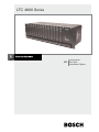
1
LTC 4600 Series
Instruction Manual
EN Fiber Optic
Transmission System
EN | 2
LTC 4600 Series | Instruction Manual | Important Safeguards
Important Safeguards
Read, follow, and retain for future reference all of
the following safety instructions. Heed all warnings
on the unit and in the operating instructions before
operating the unit.
1. Cleaning - Unplug the unit from the outlet before
cleaning. Follow any instructions provided with
the unit. Generally, using a dry cloth for cleaning
is sufficient, but a moist fluff-free cloth or leather
shammy may also be used. Do not use liquid
cleaners or aerosol cleaners.
2. Heat Sources - Do not install the unit near any
heat sources such as radiators, heaters, stoves, or
other equipment (including amplifiers) that
produce heat.
3. Ventilation - Any openings in the unit enclosure
are provided for ventilation to prevent overheating
and ensure reliable operation. Do not block or
cover these openings. Do not place the unit in an
enclosure unless proper ventilation is provided, or
the manufacturer's instructions have been
adhered to.
4. Water - Do not use this unit near water, for
example near a bathtub, washbowl, sink, laundry
basket, in a damp or wet basement, near a
swimming pool, in an outdoor installation, or in
any area classified as a wet location. To reduce
the risk of fire or electrical shock, do not expose
this unit to rain or moisture.
5. Object and liquid entry - Never push objects of
any kind into this unit through openings as they
may touch dangerous voltage points or short-out
parts that could result in a fire or electrical shock.
Never spill liquid of any kind on the unit. Do not
place objects filled with liquids, such as vases or
cups, on the unit.
6. Lightning - For added protection during a lightning
storm, or when leaving this unit unattended and
unused for long periods, unplug the unit from the
wall outlet and disconnect the cable system. This
will prevent damage to the unit from lightning and
power line surges.
7. Controls adjustment - Adjust only those controls
specified in the operating instructions. Improper
adjustment of other controls may cause damage
to the unit. Use of controls or adjustments, or
performance of procedures other than those
specified, may result in hazardous radiation
exposure.
8. Overloading - Do not overload outlets and
extension cords. This can cause fire or electrical
shock.
9. Power cord and plug protection - Protect the plug
and power cord from foot traffic, being pinched
by items placed upon or against them at electrical
outlets, and its exit from the unit. For units
intended to operate with 230 VAC, 50 Hz, the
input and output power cord must comply with
the latest versions of IEC Publication 227 or IEC
Publication 245.
Bosch Security Systems | July 08, 2008
10. Power disconnect - Units with or without
ON/OFF switches have power supplied to the
unit whenever the power cord is inserted into
the power source; however, the unit is
operational only when the ON/OFF switch is in
the ON position. The power cord is the main
power disconnect device for switching off the
voltage for all units.
11. Power sources - Operate the unit only from the
type of power source indicated on the label.
Before proceeding, be sure to disconnect the
power from the cable to be installed into the
unit.
• For battery powered units, refer to the
operating instructions.
•
For external power supplied units, use only
the recommended or approved power
supplies.
•
For limited power source units, this power
source must comply with EN60950.
Substitutions may damage the unit or cause
fire or shock.
•
For 24 VAC units, voltage applied to the unit's
power input should not exceed ±10%, or 28
VAC. User-supplied wiring must comply with
local electrical codes (Class 2 power levels).
Do not ground the supply at the terminals or
at the unit's power supply terminals.
•
If unsure of the type of power supply to use,
contact your dealer or local power company.
12. Servicing - Do not attempt to service this unit
yourself. Opening or removing covers may
expose you to dangerous voltage or other
hazards. Refer all servicing to qualified service
personnel.
13. Damage requiring service - Unplug the unit from
the main AC power source and refer servicing to
qualified service personnel when any damage to
the equipment has occurred, such as:
• the power supply cord or plug is damaged;
•
exposure to moisture, water, and/or inclement
weather (rain, snow, etc.);
•
liquid has been spilled in or on the
equipment;
•
an object has fallen into the unit;
•
unit has been dropped or the unit cabinet is
damaged;
•
unit exhibits a distinct change in performance;
•
unit does not operate normally when the user
correctly follows the operating instructions.
14. Replacement parts - Be sure the service
technician uses replacement parts specified by
the manufacturer, or that have the same
characteristics as the original parts.
Unauthorized substitutions may cause fire,
electrical shock, or other hazards.
EN | 3
LTC 4600 Series | Instruction Manual | Safety Precautions
15. Safety check - Safety checks should be
performed upon completion of service or repairs
to the unit to ensure proper operating condition.
16. Installation - Install in accordance with the
manufacturer's instructions and in accordance
with applicable local codes.
17. Attachments, changes or modifications - Only
use attachments/accessories specified by the
manufacturer. Any change or modification of the
equipment, not expressly approved by Bosch,
could void the warranty or, in the case of an
authorization agreement, authority to operate the
equipment.
Safety Precautions
DANGER! High risk:
This symbol indicates an imminently
hazardous situation such as “Dangerous
Voltage” inside the product. If not
avoided, this will result in an electrical
shock, serious bodily injury, or death.
WARNING! Medium risk:
Indicates a potentially hazardous
situation. If not avoided, this could result
in serious bodily injury or death.
CAUTION! Low risk: (without safety alert
symbol) Indicates a potentially hazardous
situation. If not avoided, this may result
in property damage or risk of damage to
the unit.
NOTICE! This symbol indicates
information or a company policy that
relates directly or indirectly to the safety
of personnel or protection of property.
Important Notices
Accessories - Do not place this unit on
an unstable stand, tripod, bracket, or
mount. The unit may fall, causing
serious injury and/or serious damage to
the unit. Use only with the cart, stand,
tripod, bracket, or table specified by
the manufacturer. When a cart is used,
use caution and care when moving the
cart/apparatus combination to avoid
injury from tip-over. Quick stops,
excessive force, or uneven surfaces may
cause the cart/unit combination to
overturn. Mount the unit per the
manufacturer's instructions.
All-p
pole power switch - Incorporate an
all-pole power switch, with a contact
separation of at least 3 mm in each
pole, into the electrical installation of
the building.
If it is needed to open the housing for
servicing and/or other activities, use
this all-pole switch as the main
Bosch Security Systems | July 08, 2008
disconnect device for switching off the voltage to
the unit.
Camera grounding - For mounting the camera in
potentially damp environments, ensure to ground the
system using the ground connection of the power
supply connector (see section: Connecting external
power supply).
Camera lens - An assembled camera lens in the
outdoor housing must comply and be tested in
accordance with UL/IEC60950. Any output or signal
lines from the camera must be SELV or Limited
Power Source. For safety reasons the environmental
specification of the camera lens assembly must be
within the environmental specification of -10 °C
(14 °F) to 50 °C (122 °F).
Camera signal - Protect the cable with a primary
protector if the camera signal is beyond 140 feet, in
accordance with NEC800 (CEC Section 60).
Coax grounding • Ground the cable system if connecting an
outside cable system to the unit.
•
Connect outdoor equipment to the unit's
inputs only after this unit has had its
grounding plug connected to a grounded
outlet or its ground terminal is properly
connected to a ground source.
•
Disconnect the unit's input connectors from
outdoor equipment before disconnecting the
grounding plug or grounding terminal.
•
Follow proper safety precautions such as
grounding for any outdoor device connected
to this unit.
U.S.A. models only - Section 810 of the National
Electrical Code, ANSI/NFPA No.70, provides
information regarding proper grounding of the mount
and supporting structure, grounding of the coax to a
discharge unit, size of grounding conductors,
location of discharge unit, connection to grounding
electrodes, and requirements for the grounding
electrode.
NOTICE! This device is intended for use in
public areas only. U.S. federal law strictly
prohibits surreptitious recording of oral
communications.
EN | 4
LTC 4600 Series | Instruction Manual | FCC & ICES Information
Your Bosch product was developed and
Moving - Disconnect the power before moving
manufactured with high-quality material
the unit. Move the unit with care. Excessive
and components that can be recycled and
force or shock may damage the unit and the
reused. This symbol means that electronic
and electrical appliances, which have
hard disk drives.
Outdoor signals - The installation for outdoor
reached the end of their working life,
signals, especially regarding clearance from
must be collected and disposed of
power and lightning conductors and transient
separately from household waste
protection, must be in accordance with
material. Separate collecting systems are
NEC725 and NEC800 (CEC Rule 16-224 and
usually in place for disused electronic and
electrical products. Please dispose of
CEC Section 60).
Permanently connected equipment -
these units at an environmentally
Incorporate a readily accessible disconnect
compatible recycling facility, per
European Directive 2002/96/EC.
Environmental statement - Bosch has a strong
device in the building installation wiring.
Pluggable equipment - Install the socket outlet
commitment towards the environment. This
near the equipment so it is easily accessible.
PoE - Never supply power via the Ethernet
unit has been designed to respect the
connection (PoE) when power is already
environment as much as possible.
Electrostatic-s
sensitive device - Use proper
supplied via the power connector.
Power disconnect - Units have power supplied
CMOS/MOS-FET handling precautions to avoid
whenever the power cord is inserted into the
electrostatic discharge.
power source. The powhe main power
NOTE: Wear required grounded wrist straps and
observe proper ESD safety precautions when
disconnect for all units.
Power lines - Do not locate the camera near
handling the electrostatic-sensitive printed
overhead power lines, power circuits, or
circuit boards.
Fuse rating - For security protection of the
electrical lights, nor where it may contact such
device, the branch circuit protection must be
power lines, circuits, or lights.
SELV - All the input/output ports are Safety
secured with a maximum fuse rating of 16A.
Extra Low Voltage (SELV) circuits. SELV circuits
This must be in accordance with NEC800 (CEC
should only be connected to other SELV
Section 60).
Grounding and polarization - This unit may be
circuits. Because the ISDN circuits are treated
equipped with a polarized alternating current
connecting the SELV circuit to the Telephone
line plug (a plug with one blade wider than the
other blade). This safety feature allows the plug
Network Voltage (TNV) circuits.
Video loss - Video loss is inherent to digital
to fit into the power outlet in only one way. If
video recording; therefore, Bosch Security
unable to insert the plug fully into the outlet,
Systems cannot be held liable for any damage
contact a locally certified electrician to replace
that results from missing video information. To
the obsolete outlet. Do not defeat the safety
minimize the risk of lost digital information,
purpose of the polarized plug.
Bosch Security Systems recommends multiple,
Alternately, this unit may be equipped with a 3-
redundant recording systems, and a procedure
pole grounding plug (a plug with a third pin for
to back up all analog and digital information.
earth grounding). This safety feature allows the
plug to fit into a grounded power outlet only. If
unable to insert the plug into the outlet,
contact a locally certified electrician to replace
the obsolete outlet. Do not defeat the safety
purpose of the grounding plug.
Bosch Security Systems | July 08, 2008
like telephone-network voltage, avoid
LTC 4600 Series | Instruction Manual | Safety Precautions
NOTICE! This device is intended for use in
public areas only. U.S. federal law strictly
prohibits surreptitious recording of oral
communications.
FCC & ICES INFORMATION
(U.S.A. and Canadian Models Only)
This device complies with part 15 of the FCC Rules.
Operation is subject to the following two conditions:
(1) This device may not cause harmful
interference, and
(2) This device must accept any interference
received, including interference that may cause
undesired operation.
NOTE: This equipment has been tested and found to
comply with the limits for a Class A digital device,
pursuant to Part 15 of the FCC Rules and ICES-003
of Industry Canada. These limits are designed to
provide reasonable protection against harmful
interference when the equipment is operated in a
commercial environment. This equipment generates,
uses, and radiates radio frequency energy and, if not
installed and used in accordance with the instruction
manual, may cause harmful interference to radio
communications. Operation of this equipment in a
residential area is likely to cause harmful
interference, in which case the user will be required
to correct the interference at his expense.
Intentional or unintentional modifications, not
expressly approved by the party responsible for
compliance, shall not be made. Any such
modifications could void the user's authority to
operate the equipment. If necessary, the user should
consult the dealer or an experienced radio/television
technician for corrective action.
The user may find the following booklet, prepared by
the Federal Communications Commission, helpful:
How to Identify and Resolve Radio-TV Interference
Problems. This booklet is available from the U.S.
Government Printing Office, Washington, DC 20402,
Stock No. 004-000-00345-4.
Bosch Security Systems | July 08, 2008
EN | 5
Disclaimer
Underwriter Laboratories Inc. (“UL”) has not tested the
performance or reliability of the security or signaling
aspects of this product. UL has only tested fire, shock
and/or casualty hazards as outlined in UL's Standard(s)
for Safety for Closed Circuit Television Equipment, UL
2044. UL Certification does not cover the performance
or reliability of the security or signaling aspects of this
product.
UL MAKES NO REPRESENTATIONS, WARRANTIES, OR
CERTIFICATIONS WHATSOEVER REGARDING THE
PERFORMANCE OR RELIABILITY OF ANY SECURITY OR
SIGNALING RELATED FUNCTIONS OF THIS PRODUCT.
Disclaimer
Copyright
This user guide is the intellectual property of Bosch
Security Systems, Inc. and is protected by copyright.
All rights reserved.
Trademarks
All hardware and software product names used in this
document are likely to be registered trademarks and
must be treated accordingly.
NOTICE! This user guide has been compiled
with great care and the information it
contains has been thoroughly verified. The
text was complete and correct at the time of
printing. The ongoing development of the
products may mean that the content of the
user guide can change without notice.
Bosch Security Systems accepts no liability
for damage resulting directly or indirectly
from faults, incompleteness or discrepancies
between the user guide and the product
described.
LTC 4600 Series | Instruction Manual | Table of Contents
EN | 6
Table of Contents
Important Safeguards . . . . . . . . . . . . . . . . . . . . . . . . . . . . . . . . . . . . . . . . . . . . . . . . . . . . . . . . . . . . . . . . . .2
FCC Information . . . . . . . . . . . . . . . . . . . . . . . . . . . . . . . . . . . . . . . . . . . . . . . . . . . . . . . . . . . . . . . . . . . . .5
1
UNPACKING . . . . . . . . . . . . . . . . . . . . . . . . . . . . . . . . . . . . . . . . . . . . . . . . . . . . . . . . . . . . . . . . . .7
2
SERVICE . . . . . . . . . . . . . . . . . . . . . . . . . . . . . . . . . . . . . . . . . . . . . . . . . . . . . . . . . . . . . . . . . . . . .7
3
DESCRIPTION . . . . . . . . . . . . . . . . . . . . . . . . . . . . . . . . . . . . . . . . . . . . . . . . . . . . . . . . . . . . . . . . .7
3.1
Model Summary . . . . . . . . . . . . . . . . . . . . . . . . . . . . . . . . . . . . . . . . . . . . . . . . . . . . . . . . . . . . . . . .7
4
INSTALLATION . . . . . . . . . . . . . . . . . . . . . . . . . . . . . . . . . . . . . . . . . . . . . . . . . . . . . . . . . . . . . . .8
4.1
Installing Rack-mount Modules . . . . . . . . . . . . . . . . . . . . . . . . . . . . . . . . . . . . . . . . . . . . . . . . . . . . .8
4.2
Installing Stand-alone Modules . . . . . . . . . . . . . . . . . . . . . . . . . . . . . . . . . . . . . . . . . . . . . . . . . . . . .8
4.3
LTC 4641, LTC 4642 Series Modules for Video Transmission . . . . . . . . . . . . . . . . . . . . . . . . . . . .9
4.4
LTC 4744, LTC 4745 Series Modules for Simultaneous 4-Channel Video Transmission . . . . . . .10
4.5
LTC 4630, LTC 4631 Series Modules for BilinxTM Video/Data Transmissions . . . . . . . . . . . . . . .11
4.6
LTC 4628, LTC 4629 Series Modules for Video + Bosch Biphase Control Code Transmission . .12
4.7
LTC 4671 Series Modules for System4/Allegiantfi Keyboard Transmission . . . . . . . . . . . . . . . . .14
4.8
LTC 4651 Series Modules for Bosch Biphase Control Code or RS-232 Transmission . . . . . . . . .15
4.9
LTC 4637 Series Rack-mount Card Cage . . . . . . . . . . . . . . . . . . . . . . . . . . . . . . . . . . . . . . . . . . . .16
5
REPLACEMENT PARTS . . . . . . . . . . . . . . . . . . . . . . . . . . . . . . . . . . . . . . . . . . . . . . . . . . . . . . . .16
6
TROUBLESHOOTING . . . . . . . . . . . . . . . . . . . . . . . . . . . . . . . . . . . . . . . . . . . . . . . . . . . . . . . . .17
7
DIMENSIONAL OUTLINES . . . . . . . . . . . . . . . . . . . . . . . . . . . . . . . . . . . . . . . . . . . . . . . . . . . . .18
Bosch Security Systems | July 08, 2008
EN | 7
LTC 4600 Series | Instruction Manual | Unpacking
1
UNPACKING
This electronic equipment should be unpacked and
handled carefully. In addition to a copy of these
instructions, check for the following items:
1. Stand-alone units:
•
Individual LTC 4600 or LTC 4700 Series
Module, and associated Power Supply
2. Rack-mount units:
•
Individual LTC 4600 or LTC 4700 Series
Rack Plug-in Module
•
Rack / Power Supply Card Cage
•
Card Cage with integral Power Supply and
applicable AC Power Cord
If an item appears to have been damaged in shipment,
replace it properly in its carton and notify the shipper.
If any items are missing, notify your Bosch Security
Systems, Inc. Sales Representative or Customer Service.
The shipping carton is the safest container in which the
unit may be transported. Save it for possible future use.
2
SERVICE
3
DESCRIPTION
The LTC 4600 and LTC 4700 Series are transmission
systems that provide efficient, high quality video and data
transmission via multimode fiber optic cable for improved
CCTV system performance. Signals are immune to
ground loops, radio frequency interference (RFI),
electromagnetic interference (EMI), and cross talk because
the video carrier is infrared light, and is transmitted
through a nonconductive fiber optic cable. Interferencefree operation ensures reliable service. Unlike microwave,
wire, and coaxial cable transmission systems, fiber optic
transmission is difficult, if not impossible, to tap. And,
since fiber optic cable is nonconductive and does not
radiate a signal, it is difficult to detect and locate. These
compact devices are available in a surface mount
enclosure or in a modular style package that can be rackmounted using an optional EIA 19" compatible rack unit.
3.1
Model Summary
A list of available models is shown below. Complete
specifications can be found on the LTC 4600 Series
Data Sheet that can be downloaded from
www.boschsecuritysystems.com.
If the unit ever needs repair service, the customer should
contact the nearest Bosch Security Systems, Inc. Service
Center for return authorization and shipping instructions.
Model No.
Description / Use
LTC 4641, LTC 4642 Series
Single Channel Video Transmissions
Service Centers
LTC 4744, LTC 4745 Series
4-Channel Video Transmissions
LTC 4630, LTC 4631 Series
BilinxTM Video/Data Transmissions
LTC 4628, LTC 4629 Series
Video/Biphase Data Transmissions
LTC 4671 Series
RS-485 Allegiant/DivarTM/System4 Keyboard
USA
Telephone: 800-366-2283 or 585-340-4162
Fax: 800-366-1329
Email: [email protected]
Customer Service
Telephone: 888-289-0096
Fax: 585-223-9180
Email: [email protected]
Technical Support
Telephone: 800-326-1450
Fax: 585-223-3508 or 717-735-6560
Email: [email protected]
Repair Center
Telephone: 585-421-4220
Fax: 585-223-9180 or 717-735-6561
Email: [email protected]
Canada
Telephone: 514-738-2434
Fax: 514-738-8480
Europe, Middle East & Asia Pacific Region
Telephone: 44 (0) 1495 274558
Fax: 44 (0) 1495 274280
Email: [email protected]
Bosch Security Systems | July 08, 2008
Data Transmissions
LTC 4651 Series
RS-232 / Biphase Data Transmissions
LTC 4637 Series
Card Cage Enclosure for Rack-mount
Models
EN | 8
LTC 4600 Series | Instruction Manual | Installation
4
INSTALLATION
4.1
Installing Rack-mount Modules
1. Install the LTC 4637 Series card cage unit as
described in a later section of this document.
2. Install the fiber optic plug-in module into any
available slot of the LTC 4637 Series rack-mount
card cage. Certain modules, such as the LTC 4744
and LTC 4745 units are double width, so they
require two (2) available rack-mount slots.
•
•
Push the module in completely, so that the 3-pin
connector on the rear of the card engages the
3-pin connector on the back plane.
Each fiber optic plug-in module is equipped
with a power LED indicator that illuminates
when power is applied to the rack unit.
3. Fasten the module into place by tightening the front
panel captive screws into the appropriate mating
holes with a small flat blade screwdriver.
4. Connect the applicable video and/or data
connections to the appropriate connectors, located
either on the front or rear of the module. Refer to
the example diagrams later in the individual
sections.
4.2
Installing Stand-alone Modules
1. Choose an appropriate flat surface where the
stand-alone module can be conveniently mounted,
then mark the locations of the keyhole slots on the
mounting flanges.
•
The LTC 4641 Series Video Transmitter is
small enough to be installed inside a camera
housing. If applicable, mount the module in a
convenient location where it will not obstruct
access to other items in the housing.
2. Install the appropriate mounting screws (not
supplied) into the keyhole locations. Allow
sufficient leeway under the screw head for the
module to be mounted.
•
For the LTC 4641 Series Video Transmitter, a
single mounting hole is provided to secure the
module.
3. For modules other than the LTC 4641 Series,
position the module over screw heads, slide to one
side, and then tighten screws.
4. Connect the cable from the supplied power supply
to the power input terminals on the module.
5. Connect the supplied power supply to an
appropriate power source.
6. Connect the applicable video and/or data
connections to the appropriate connectors on the
module. Refer to example diagrams for exact
details.
Bosch Security Systems | July 08, 2008
EN | 9
LTC 4600 Series | Instruction Manual | Installation
4.3
LTC 4641, LTC 4642 Series Modules for Video Transmission
4.3.1 Indicators / Operation
1. The POWER LED illuminates when AC power is applied to the unit.
2. LTC 4642/60 and LTC 4642/50 units: The Video Out / AGC LED illuminates GREEN when a video signal
is being received, or RED if a video signal is not present.
Typical Configurations:
CAMERA
MONITOR
LTC 4642
VIDEO RECEIVER
OPTICAL IN
POWER
SUPPLY
LTC 4641
VIDEO TX
NC 3
+9 -12VDC 2
GND 1
COAX
CABLE
BLACK with
WHITE
MARKINGS
POWER
POWER
BLACK
-2
+12 VDC - 1
BLACK
BLACK with
WHITE
MARKINGS
POWER
SUPPLY
AC
POWER
LTC 4642/x0
Stand-alone Model
LTC 4641/x0
Stand-alone Model
OPTICAL
OUT
VIDEO OUT
VIDEO OUT / AGC
Up to 4 km (2.5 mi) using
62.5/125 micron
Multimode Fiber Optic Cable
Figure 1 LTC 4641 Series Stand-alone Transmitter and LTC 4642 Series Stand-alone Receiver
LTC 4642/00
Rack-mount Model
(in LTC 4637 Card Cage)
CAMERA
VIDEO
RECEIVER
OPTICAL
IN
POWER
SUPPLY
LTC 4641
VIDEO TX
NC 3
+9 - 12VDC 2
GND 1
VIDEO
OUT
BLACK with
WHITE
MARKINGS
VIDEO
OUT
AGC
POWER
IN from
RACK
BLACK
POWER
MONITOR
OPTICAL
OUT
LTC 4641/x0
Stand-alone Model
Up to 4 km (2.5 mi) using
62.5/125 micron
Multimode Fiber Optic Cable
Figure 2 LTC 4641 Series Stand-alone Transmitter and LTC 4642 Series Rack-mount Receiver
Bosch Security Systems | July 08, 2008
LTC 4642
COAX
CABLE
Side
View of
Rear
Front
View
EN | 10
LTC 4600 Series | Instruction Manual | Installation
4.4
LTC 4744, LTC 4745 Series Modules
for Simultaneous 4-Channel Video
Transmission
4.4.1 Indicators / Operation
1. The POWER LED illuminates when AC power is
applied to the unit.
2. LTC 4744/00 units: Although this module provides
both front and rear mounted BNC input connectors
for installation convenience, each input channel is
capable of accepting only a single video signal.
3. LTC 4744/60, LTC 4744/50, and LTC 4744/00
units: The respective CAMERA ON LED
illuminates when a video signal is connected to its
input.
4. LTC 4745/60, LTC 4745/50, and LTC 4745/00
units: The LOCAL VIDEO ON LED illuminates
when the respective channel of the unit is providing
a video signal output. The REMOTE VIDEO ON
LED illuminates when a video signal is connected
to the respective input of the LTC 4744 Series
transmitter.
NOTE: Avoid simultaneously connecting video signals
to both the front BNC and rear BNC of the same
channel. Also, since each video channel is factory
terminated to 75 ohm, unused BNCs should not be
used for loop-through video connections.
Typical Configuration:
CAMERA
1
CAMERA
LTC 4744
4 CHANNEL DIGITAL
VIDEO TRANSMITTER
2
3
CAMERA
Up to 3 km (1.9 mi) using
62.5/125 micron
Multimode Fiber Optic Cable
OPTICAL OUT
4
POWER
CAMERA ON
-2
+12VDC - 1
POWER
BLACK
BLACK with
WHITE
MARKINGS
CAMERA
POWER
SUPPLY
AC
POWER
Video Signal
LOCAL VIDEO ON
REMOTE VIDEO ON
MONITOR
LTC 4745
4 CHANNEL DIGITAL
VIDEO RECEIVER
1
OPTICAL
INPUT
CHANNEL 1
2
CHANNEL 2
VIDEO
OUTPUT
CHANNEL 3
CHANNEL 4
RECEIVER
LOCKED
POWER
Video
Coax
3
Video
Coax
4
POWER
-2
+12VDC - 1
BLACK
BLACK with
WHITE
MARKINGS
Typical Digital Video Recorder,
Matrix Switcher, Multiplexer, or other
Video Management Device
POWER
SUPPLY
AC
POWER
Figure 3 LTC 4744 Series Stand-alone Transmitter and LTC 4745 Series Stand-alone Receiver
Bosch Security Systems | July 08, 2008
EN | 11
LTC 4600 Series | Instruction Manual | Installation
4.5
LTC 4630, LTC 4631, Series Modules
for Bilinx Video/Data Transmissions
4.5.2 Indicators / Operation
1. The POWER LED illuminates when AC power
is applied to the unit.
4.5.1 Important Considerations
1. To ensure proper Bilinx communications, the
video output of the LTC 4631 Series module
must be terminated into a proper 75 ohm load.
If improper video looping connections are used,
erratic or no camera P/T/Z control may result.
2. LTC 4631 Series units: Once the video signal
and fiber optic connections have been
completed, the state of the VIDEO OUT and
AGC LED indicators should be examined. If
both are GREEN, test the VIDEO OUT LED
action by temporarily removing the video signal
from the LTC 4630 module. The LED should
turn RED.
2. Do not exceed the published distance
specification for Bilinx communications. Erratic
or no camera P/T/Z control may result. Refer to
the data sheet for product specifications.
If necessary, adjust the AGC control in small
increments until the correct LED actions are
obtained. Marginal signal strengths are indicated
by an AMBER color LED, and a RED LED
indicates video loss, or that further adjustments
are needed. The adjustment is sensitive. Adjust
the control too high, and the VIDEO OUT
LED may remain lit even when the video signal
is removed or lost. If adjusted too low, the
VIDEO OUT LED may remain RED even if a
video signal is present.
3. Although these modules are compatible with
Bilinx up-the-coax communication technology
found in Bosch Security System products,
compatibility is not guaranteed when used with
similar technologies employed by other
manufacturers.
Typical Configuration:
LTC 4630
BILINX/UP THE COAX
VIDEO TRANSMITTER + DATA RECEIVER
OPTICAL CABLE
VIDEO + Bilinx DATA
VIDEO IN
BLUE
POWER
AC - 3
-2
AC - 1
POWER
24VAC CT
-2
+12VDC - 1
+12VDC
GREEN
BROWN
POWER
SUPPLY
Bilinx-ENABLED
AUTODOME SERIES
P/T/Z CAMERA
AC
POWER
VIDEO + Bilinx DATA
Up to 600 m (2000 ft) using
62.5/125 micron
Multimode Fiber Optic Cable
LTC 4631
BILINX/UP THE COAX
VIDEO RECEIVER + DATA TRANSMITTER
TYPICAL ALLEGIANT SERIES SWITCHER/CONTROLLER,
DIVAR DIGITAL VIDEO RECORDER, BILINX
CONFIGURATION TOOL PROGRAM, OR OTHER BOSCH
SECURITY SYSTEMS CONTROL SYSTEM
OPTICAL CABLE
VIDEO
BOSCH
ALLEGIANT Video System
CODE OUT
VIDEO OUT
STATUS
BATTERY LOW
POWER
DATA
VIDEO
AGC LEVEL
ALARM
BOSCH
ALLEGIANT Bilinx Data Interface
Status/Power
BOSCH
AGC
Prod
Mon
Shot
Clr
VIDEO OUT
POWER
POWER
-2
+12 VDC - 1
VIDEO + Bilinx DATA
BLACK
BLACK with
WHITE
MARKINGS
LTC 8016 ALLEGIANT
BILINX DATA INTERFACE
2
3
4
5
6
7
8
9
0
INTUIKEY® SERIES KEYBOARD
POWER
SUPPLY
AC
POWER
Figure 4 LTC 4630 Series and LTC 4631 Series Stand-alone Bilinx Transceivers
Bosch Security Systems | July 08, 2008
1
EN | 12
LTC 4600 Series | Instruction Manual | Installation
IntuiKey Series
Keyboard
8
POWER
SUPPLY
POWER
Figure 5 LTC 4629 Series Stand-alone Transceiver Used with AutoDomefi Fiber Unit
POWER
-2
+12VDC - 1
BLACK
with
WHITE
Markings
Video
Coax
BLACK
AC
POWER
9
6
5
7
0
4
Mo
n
2
Pro
d
Cl
r
POWER
BOSCH
STATUS BATTERY LOW
CODE OUT ALARM
VIDEO OUT
RS232
RS422
VIDEO OUT
DATA IN
Typical Allegiant Series
Switcher, System4 Series
Multiplexer, or other Device Keyboard
Generating BOSCH Biphase Data Cable
Control Code
ALLEGIANT Video System
Data "+" to Pin 1
Data "-" to Pin 3 Biphase Control
Code Output
Video
Coax
BOSCH AutoDome Series with
Integrated Fiber Optic Module
Typical Configurations:
Up to 4 km (2.5 mi) using
62.5/125 micron
Multimode Fiber Optic Cable
If the supplied resistor is damaged or lost, any locally
obtained conventional 1/4 watt carbon resistor
between 100 and 120 ohms will suffice.
LTC 4629
VIDEO RECEIVER + DATA TRANSMITTER
Video Signal
4.6.2 Optional Connection
Because of signal amplitude variations and possible
EMI/RFI noise interference in the Biphase control data
line, the pan/tilt device may operate erratically or
intermittently when first connected. If this is the case,
add the supplied 120 ohm termination resistor across
the data connections of the LTC 4629 fiber optic
module located at the controller site.
Biphase Control Data
OPTICAL
IN/OUT
3. LTC 4629/60, LTC 4629/50, and LTC 4629/00
units: The VIDEO OUT LED illuminates GREEN
when a valid video signal is present on the
LTC 4628 Series Transmitter, or RED if no video is
present. The DATA IN LED illuminates RED if no
data is being received on the optical signal, and
flashes YELLOW as data is received.
-6
-5
-4
-DATA - 3
-2
+DATA - 1
Refer to Text
Regarding Supplied
120 ohm Resistor
2. LTC 4628/60, LTC 4628/50, and LTC 4628/00
units: The VIDEO PRESENT LED illuminates
GREEN when a valid video signal is present, or
RED if no video is being received. The DATA
RECEIVE LED illuminates RED when no data is
received, and flashes YELLOW as data is received.
1
MONITOR
4.6.1 Indicators / Operation
1. The POWER LED illuminates when AC power is
applied to the unit.
Bosch Security Systems | July 08, 2008
3
Sh
ot
BOSCH
4.6 LTC 4628, LTC 4629 Series Modules
for Video + Bosch Biphase Control
Code Transmission
Video Coax
AC - 3
-2
-2
AC - 1 +12VDC - 1
24VAC CT +12VDC
Typical BOSCH AutoDome
Series Camera
POWER
VIDEO IN
OPTICAL IN/OUT
D-4
DATA RS-232 GND - 3
OUT RS-422
+D - 2
-D - 1
Up to 4 km (2.5 mi) using
62.5/125 micron
Multimode Fiber Optic Cable
Video
Coax
AC
POWER
POWER
SUPPLY
Biphase Control Code
GREEN
BROWN
BLUE
Data "-" to Pin 1
Data "+" to Pin 2
Video
Coax
Front
View
LTC 4628
POWER
VIDEO
PRESENT
DATA
RECEIVE
DATA REC
VIDEO XTMR
Side
View of
Rear
POWER
IN from
RACK
VIDEO
IN
OPTICAL
IN/OUT
Data "-" to Pin 1
DATA OUT
Data "+" to Pin 2
Up to 4 km (2.5 mi) using
62.5/125 micron
Multimode Fiber Optic Cable
Figure 7 LTC 4628/00 and LTC 4629/00 Rack-mount Transceivers
Typical BOSCH AutoDome
Series Camera
Biphase
Control
Code
LTC 4628/00
Rack-mount Model
(in LTC 4637 Card Cage)
Figure 6 LTC 4628 and LTC 4629 Series Stand-alone Transceivers
POWER
VIDEO PRESENT
DATA RECEIVE
LTC 4628
VIDEO TRANSMITTER + DATA RECEIVER
1234
Bosch Security Systems | 10 October 2003
Biphase Control Data
Video Signal
POWER
VIDEO OUT
DATA IN
-2
+12VDC - 1
+
VIDEO REC
Front
View
LTC 4629
POWER
AGC
VIDEO
OUT
DATA
IN
DATA XTMR
Side
View of
Rear
POWER
IN from
RACK
CODE OUT ALARM
STATUS
POWER
BOSCH
Keyboard
Data Cable
BATTERY LOW
Video
Coax
Keyboard
Data Cable
POWER
BOSCH
Video
Coax
STATUS BATTERY LOW
Typical Allegiant Series
Switcher, System4 Series
Multiplexer, or other Device
Generating BOSCH Biphase
Control Code
ALLEGIANT Video System
Biphase Control
Code Output
Refer to Text
Regarding Supplied
120 ohm Resistor
Data "-" to Pin 3
Video
Coax
CODE OUT ALARM
Typical Allegiant Series
Switcher, System4 Series
Multiplexer, or other Device
Generating BOSCH Biphase
Control Code
ALLEGIANT Video System
AC
POWER
Data "+" to Pin 1
VIDEO
OUT
DATA IN
OPTICAL
IN/OUT
POWER
SUPPLY
BLACK
Video
Coax
Biphase Control
Code Output
Refer to Text
Regarding Supplied
120 ohm Resistor
Data "-" to Pin 3
Data "+" to Pin 1
BLACK with
WHITE
Markings
LTC 4629/00
Rack-mount Model
(in LTC 4637 Card Cage)
POWER
-5
-4
-DATA - 3
-2
+DATA - 1
-6
OPTICAL
IN/OUT
VIDEO OUT
RS422 RS232
LTC 4629
VIDEO RECEIVER + DATA TRANSMITTER
Biphase Control Data
123456
Video Signal
2
5
8
4
7
0
1
Pro
d
Mo
n
9
6
3
Sh
ot
BOSCH
5
8
4
7
0
2
Pro
d
1
Mo
n
Sh
ot
9
6
3
BOSCH
IntuiKey Series
Keyboard
Cl
r
MONITOR
IntuiKey Series
Keyboard
Cl
r
MONITOR
LTC 4600 Series | Instruction Manual | Chapter
EN | 13
EN | 14
LTC 4600 Series | Instruction Manual | Installation
4.7
LTC 4671 Series Modules for
System4 / Allegiant Keyboard
Transmission
1. The supplied 120 ohm resistor must be installed
across the external data connections when these
fiber optic modules are used with certain controller
devices. Follow the guidelines below, however,
because of differences between the hardware of
new and old controller units, these cases are not
absolute. If a configuration does not work when
first connected without using a termination resistor,
try adding the termination resistor across the data
connections of the fiber optic module located at the
controller site.
A termination resistor is typically required when a
module is connected to the following controller
devices:
•
Allegiant LTC 8100 Series main CPU bays
•
Allegiant LTC 8200 Series main CPU bays
•
Allegiant LTC 8300 Series main CPU bays
•
Allegiant LTC 8900 Series main CPU bays
•
LTC 8714 Series Allegiant Keyboard Expander
accessory units sold prior to 2002
•
LTC 2604 Series Multiplexer Keyboard
Expander
A termination resistor is typically NOT required when
a module is connected to the following controller
devices:
• Allegiant LTC 8500 Series main CPU bays
•
Allegiant LTC 8600 Series main CPU bays
•
Allegiant LTC 8800 Series main CPU bays
•
LTC 8714 Series Allegiant Keyboard Expander
accessory units sold during or after 2002
If the supplied resistor is damaged or lost, any locally
obtained conventional 1/4 watt carbon resistor
between 120 ohm and 390 ohm should suffice.
2. The POWER LED will light when AC power is
applied to the unit.
3. The DATA XTMR LED will flash as the external
data received by the unit is being optically
transmitted.
4. The DATA REC LED will flash as optical data is
being received by the unit.
Typical Configuration:
Typical Allegiant Main CPU Bay or Allegiant Keybord Port Expander
ALLEGIANT Video System
CODE OUT ALARM
STATUS BATTERY LOW
POWER
Separate Video
Transmission Link
To Allegiant Keyboard Port
Using Keyboard Data Cable
LTC 4671/00
RS485
TRANSCEIVER
Rack-mount Model
(in LTC 4637 Card Cage)
XTMR
4
3
2
1
123456
REC
2- Data "-"
1- Data "+"
Refer to Text
Regarding Supplied
120 Resistor
BOSCH
POWER
IN from
RACK
LTC 4771
DATA
REC
LTC 4671
RS485
-4
-3
-- Data - 2
+ Data - 1
DATA
XTMR
PWR
Front
View
LTC
LTC8557
8557
Junction
JunctionBox
Box
MONITOR
4
3
2
1
LTC 8557
Junction Box
Keyboard
Data Cable
AC
POWER
POWER
POWER
-2
POWER
SUPPLY
+12VDC - 1
Side View
of Rear
Figure 8 LTC 4671 Series Stand-alone Transceiver and LTC 4671 Rack-mount Transceiver
Bosch Security Systems | July 08, 2008
Mo
n
Sh
ot
1
2
3
4
5
6
7
8
9
0
POWER
SUPPLY
AC
POWER
Up to 4 km (2.5 mi) using
62.5/125 micron
Multimode Fiber Optic Cable
BOSCH
Pro
d
Cl
r
IntuiKey Series
Keyboard
EN | 15
LTC 4600 Series | Instruction Manual | Installation
4.8 LTC 4651 Series Modules for Bosch
Biphase Control Code or RS-232
Transmission
4.8.1 Indicators / Operation
1. The POWER LED will light when AC power is
applied to the unit.
2. The TRANSMIT LED flashes as the external
data received by the unit is optically
transmitted.
3. The RECEIVE LED flashes as optical data is
received by the unit.
Typical Configurations:
VIDEO
Separate Video Signal
Transmission Link
MONITOR
VIDEO
BIPHASE
CONTROL
DATA
CABLE
VIDEO
BIPHASE
CONTROL
DATA
AUTODOME SERIES
P/T/Z CAMERA
ALLEGIANTideo
V Sy
stem
CODE OUT
LTC4651
RS-232/BI-PHAS
E TR
ANSCEIVER
LTC4651
RS-232/BI-PHAS
E TR
ANSCEIVER
RECEIVE
TRANSMIT
FIBER
OPTIC
CABLE
8
7
6
5
4
3
2
1
+12 VDC
POWER
RECEIVE
RS232 Rx/+ DA
TA IN
- DATA IN
+ DATA OUT
- DATA OUT
RS232 TR
ANSMIT
TRANSMIT
Up to 3.5 km (2 mi) Using
62.5/125 micron
Multimode Fiber Optic C
able
ALARM
STATUS
BATTERY OW
L
Control System
Generating Biphase
Control Code
8
7
6
5
4
3
2
1
+12 VDC
POWER
RS232 Rx/+ DA
TA IN
- DATA IN
+ DATA OUT
- DATA OUT
RS232 TR
ANSMIT
FIBER
OPTIC
CABLE
Figure 9 LTC 4651 Series Stand-alone Transceivers Biphase Code Transmission
RS-232
DATA
BOSCH
BOSCH
ALLEGIANTideo
V Sy
stem
CODE OUT
ALARM
STATUS
BATTERY OW
L
POWER
GROUND
GROUND
RS232 Rx/+ DA
TA IN
- DATA IN
+ DATA OUT
- DATA OUT
RS232 TR
ANSMIT
BOSCH
RS-232
Data
Interface
Cable
GROUND
GROUND
RS232 Rx/+ DA
TA IN
- DATA IN
+ DATA OUT
- DATA OUT
RS232 TR
ANSMIT
RECEIVE
Optical Out
1234567
RS232/
BIPHASE
1234567
RS232/
BIPHASE
TYPICAL ALLEGIANT SERIES
SWITCHER/C
ONTROLLER
TRANSMIT
RECEIVE
RS-232
Data
Interface
Cable
Optical In
POWER
IN from
RACK
POWER
Optical Out
LTC4651
TRANSMIT
Optical In
POWER
FIBER
OPTIC
CABLES
LTC4651
Front
View
Front
View
POWER
IN from
RACK
Side View
of Rear
Up to 3.5 km (2 mi) using
62.5/125 micron
Multimode Fiber Optic C
able
Side View
of Rear
FIBER
OPTIC
CABLES
Figure 10 LTC 4651 Series Rack-mount Transceivers RS-232 Transmission
Bosch Security Systems | July 08, 2008
TYPICAL PCRUNNING
ALLEGIANT MASTER
ONTROL
C
SOFTW
ARE PR
OGRAM
1 2 3
4 5 6
7 8 9
0
POWER
EN | 16
LTC 4600 Series | Instruction Manual | Replacement Parts
4.9
LTC 4637 Series Rack-mount
Card Cage
4.9.1 Installation
1. Install the LTC 4637 Series Rack-mount into a
standard EIA 19in. rack, using user-supplied rackmounting hardware. Be careful to not damage
exposed objects on the back of the card cage unit.
2. If a secondary earth ground connection is needed, a
grounded wire with a ground lug can be attached to
the rack using the protruding screw provided on
the right side of the chassis.
3. Connect the supplied AC voltage line cord between
the rear of the power supply and the appropriate
AC voltage source.
4. Fiber optic plug-in modules can be installed into
any of the available 14 slots of the card cage. Most
modules require only a single slot width, but others,
such as the LTC 4644 and LTC 4645 Series,
require two slot widths.
4.9.3 LTC 4637 Maintenance / Service
Information
1. The power supply is fused with a 1A slow blow
fuse. To replace the fuse, remove the AC power
line cord from the power supply, and carefully pry
out the fuse module above the AC connector.
2. The 3-pin connector on the rack supplies a 20VAC
center tapped voltage, and is the only electrical
connection from the back plane to a plug-in
module. Each plug-in module contains its own
fuse, so in the unlikely event of a module failure,
the other modules in the rack remain unaffected.
3. The power supply is modular in construction, and
can be replaced in the event of damage or failure.
To remove the power supply from the rack:
a) Disconnect the AC line cord and power supply
cable from the circuit board back plane, located
on the rear of the card cage.
b) Loosen the four (4) screws located at the front of
the power supply using a small flat blade
screwdriver. Slide the power supply out of
the card cage.
5. If desired, LTC 4600/00 blank panels (ordered
separately) may be installed to cover unused slots.
A single blank panel covers a single slot opening.
c) Reverse the above procedure to install the power
supply into the card cage.
6. Refer to the sections of this manual for specific
installation instructions regarding the plug-in
modules.
4.9.2 Indicators
1. LTC 4637 Series front panel LED illuminates when
AC power is applied to the unit.
2. Each fiber optic plug-in module is equipped with a
POWER LED indicator that illuminates when
power is applied to the rack unit.
LTC 4637/60
power supply
Power
BOSCH
Figure 11 LTC 4637 Series Typical Installation
Bosch Security Systems | July 08, 2008
5
REPLACEMENT PARTS
UPA-1509-60
Power Supply for 120VAC Standalone Modules
UPA-1509-50
Power Supply for 230VAC Standalone Modules
LTC 4600 Series | Instruction Manual | Troubleshooting
6
EN | 17
TROUBLESHOOTING
Video Links:
Video Problems
Verify that a valid video signal is being applied to the transmitter module.
Verify the integrity of the coax connections between devices and fiber modules.
Verify that the correct fiber cable is being used (i.e., multimode only).
Verify that the length of the fiber optic cable and associated splices do not exceed the allowable optical
loss budget.
Power Problems
Verify the power cable connections between modules and power pack.
Verify that the power pack is connected to the appropriate AC power source.
Data Transmission
Verify the polarity of data connections between devices.
Problems
If data transmission is not working over the fiber link, verify that a direct connection between the
Data Links:
associated products operates correctly.
Verify the integrity of the data cable connections between devices and fiber modules.
Verify that the correct fiber cable is being used (i.e., multimode only).
Verify that the length of the fiber optic cable and associated splices do not exceed the allowable optical
loss budget.
When using LTC 4671 Series RS-485 modules, review the text regarding the usage of termination
resistor.
Power Problems
Verify power cable connections between modules and power pack.
Verify that the power pack is connected to the appropriate AC power source.
LTC 4637 Series Rack-mount Configurations:
Power LED on the Power
Verify that the AC line cord is connected to an appropriate AC voltage source.
Supply Fails to Light
Check and/or replace the AC fuse located near the AC connector on the rear of the power supply.
Power LED on all Plug-in
Verify that the power supply cable to the circuit board back plane (located on the rear of the card cage) is
Modules Fails to Light
properly connected.
Power LED on Individual
Verify that affected plug-in modules are properly seated onto the back plane 3-pin connector.
Plug-in Modules Fails to
Verify that fuses on the affected plug-in modules are intact. If not, return for repair.
Light
Bosch Security Systems | July 08, 2008
EN | 18
LTC 4600 Series | Instruction Manual | Dimensional Outlines
7
DIMENSIONAL OUTLINES
41
1.6
LTC 4641
VIDEO TX
NC 3
+9-12VDC 2
GND 1
64
2.5
25.4
1.0
30
1.19
mm
in
Figure 12 Stand-alone Modules: LTC 4641/60, LTC 4641/50
107
4.2
25
1.0
89
3.5
78
3.06
76
3.0
Figure 13 Stand-alone Modules: LTC 4642/50, LTC 4642/60,
LTC 4651/60, LTC 4651/50
Bosch Security Systems | July 08, 2008
mm
in
EN | 19
LTC 4600 Series | Instruction Manual | Dimensional Outlines
178
7.0
25
1.0
128
5.0
125
4.9
113
4.45
LTC 4xxx
mm
in
140
5.5
Figure 14 Stand-alone Modules: LTC 4744/50,
LTC 4744/60, LTC 4671/60, LTC 4671/50,
LTC 4628/60, LTC 4628/50, LTC 4629/60,
LTC 4629/50, LTC 4630/50, LTC 4630/60,
LTC 4631/50, LTC 4631/60
1 LTC 4637
Rack Width
mm
in
Figure 16 Rack-mount Modules: LTC 4600/00,
LTC 4642/00, LTC 4651/00, LTC 4671/00,
LTC 4628/00, LTC 4629/00, LTC 4630/00,
LTC 4631/00
178
7.0
50.0
2.0
128
5.0
125
4.9
113
4.45
LTC 46xx
mm
in
2 LTC 4637
Rack Widths
140
5.5
mm
in
Figure 17 Rack-mount Modules: LTC 4744/00,
LTC 4745/00
LTC 4637/60
POWER SUPPLY
Figure 15 Stand-alone Modules: LTC 4745/50,
LTC 4745/60
POWER
BOSCH
483
19
95
3.75
38
1.5
Figure 18 Card Cage: LTC 4637/60, LTC 4637/50
Bosch Security Systems | July 08, 2008
133
5.25
(3U)
mm
in
Americas
Bosch Security Systems, Inc.
850 Greenfield Road
Lancaster, Pennsylvania 17601
USA
Telephone+1 888-289-0096
Fax
+1 585-223-9180
Email: [email protected]
www.boschsecurity.us
Europe, Middle East, Africa:
Bosch Security Systems B.V.
P.O. Box 80002
5600 JB Eindhoven, The Netherlands
Phone: + 31 40 2577 284
Fax: +31 40 2577 330
[email protected]
www.boschsecurity.com
© 2008 Bosch Security Systems, Inc.
F01U087540 08-28 | Updated July 08, 2008 | Data subject to change without notice.
Asia-Pacific:
Bosch Security Systems Pte Ltd
38C Jalan Pemimpin
Singapore 577180
Phone: +65 6319 3450
Fax: +65 6319 3499
[email protected]
www.boschsecurity.com