1
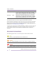
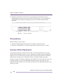
Altitude™ 4521 Series Access Point
Installation Guide
Extreme Networks, Inc.
3585 Monroe Street
Santa Clara, California 95051
(888) 257-3000
(408) 579-2800
http://www.extremenetworks.com
Published: October 2012
Part number: 120790-00 Rev 02
AccessAdapt, Alpine, Altitude, BlackDiamond, EPICenter, ExtremeWorks Essentials, Ethernet
Everywhere, Extreme Enabled, Extreme Ethernet Everywhere, Extreme Networks, Extreme Standby
Router Protocol, Extreme Turbodrive, Extreme Velocity, ExtremeWare, ExtremeWorks, ExtremeXOS, Go
Purple Extreme Solution, ExtremeXOS ScreenPlay, ReachNXT, Sentriant, ServiceWatch, Summit,
SummitStack, Triumph, Unified Access Architecture, Unified Access RF Manager, UniStack, the
Extreme Networks logo, the Alpine logo, the BlackDiamond logo, the Extreme Turbodrive logo, the
Summit logos, and the Powered by ExtremeXOS logo are trademarks or registered trademarks of
Extreme Networks, Inc. or its subsidiaries in the United States and/or other countries.
sFlow is a registered trademark of InMon Corporation.
Specifications are subject to change without notice.
All other registered trademarks, trademarks, and service marks are property of their respective
owners.
© 2012 Extreme Networks, Inc. All Rights Reserved.
Altitude™ 4521 Series Access Point Installation Guide
2
Table of Contents
Chapter 1: Introduction....................................................................................................5
Document Conventions............................................................................................................... 6
Warnings..................................................................................................................................... 7
Site Preparation .......................................................................................................................... 7
Package Contents ...................................................................................................................... 7
Features...................................................................................................................................... 8
Chapter 2: Hardware Installation ....................................................................................9
Installation Instructions ............................................................................................................... 9
Precautions ............................................................................................................................... 10
Access Point Placement ........................................................................................................... 10
Antenna Options ................................................................................................................ 11
Power Injector System....................................................................................................... 12
Wall Mount Installation.............................................................................................................. 14
Suspended Ceiling T-Bar Installation........................................................................................ 16
Above the Ceiling (Plenum) Installation ................................................................................... 18
LED Indicator ............................................................................................................................ 20
Chapter 3: Defining a Basic Configuration ..................................................................23
Using the Initial Setup Wizard................................................................................................... 23
Chapter 4: Specifications ..............................................................................................47
Electrical Characteristics........................................................................................................... 47
Physical Characteristics............................................................................................................ 47
Radio Characteristics................................................................................................................ 48
Chapter 5: Regulatory Information ...............................................................................49
Regulatory Overview................................................................................................................. 49
Wireless Device Country Approvals.......................................................................................... 49
Country Selection – Note for AP & Wireless Controller ..................................................... 50
Frequency of Operation – FCC and IC .............................................................................. 50
Health and Safety Recommendations ...................................................................................... 51
Warnings for the use of Wireless Devices ......................................................................... 51
Potentially Hazardous Atmospheres – Fixed Installations................................................. 51
Altitude™ 4521 Series Access Point Installation Guide
3
Table of Contents
Safety in Hospitals............................................................................................................. 51
RF Exposure Guidelines ........................................................................................................... 52
Safety Information ............................................................................................................. 52
International .............................................................................................................................. 52
EU ............................................................................................................................................. 52
US and Canada ........................................................................................................................ 53
Power Supply............................................................................................................................ 53
Radio Frequency Interference Requirements – FCC................................................................ 54
Radio Frequency Interference Requirements – Canada ......................................................... 54
Radio Transmitters ............................................................................................................ 55
CE Marking and European Economic Area (EEA).................................................................... 55
Statement of Compliance.......................................................................................................... 55
Waste Electrical and Electronic Equipment (WEEE) ................................................................ 56
Japan (VCCI) - Voluntary Control Council for Interference Class B ITE .................................. 58
Korea Warning Statement for Class B ITE ............................................................................... 58
Other Countries ........................................................................................................................ 59
Australia............................................................................................................................. 59
Brazil.................................................................................................................................. 59
Chile .................................................................................................................................. 59
Mexico ............................................................................................................................... 59
Taiwan ............................................................................................................................... 60
Korea ................................................................................................................................. 61
Chapter 6: Customer Support .......................................................................................62
Registration............................................................................................................................... 62
Documentation.......................................................................................................................... 63
Altitude™ 4521 Series Access Point Installation Guide
4
1
Introduction
CHAPTER
Altitude™ 4521 Series Access Points are components of Extreme Networks® Wireless
Mobility System. An Altitude 4521 Series Access Point links wireless 802.11a/b/g/n devices
to the Summit® WM3000 Series Controller, enabling the growth of your wireless network
with a cost-effective alternative to standard Access Points. The Altitude 4521 Series Access
Point is an enterprise class 802.11n Access Point, installed in minutes anywhere a CAT-5e
(or better) cable is located. An Altitude 4521 Series Access Point utilizes a setup wizard to
define its operational mode as either a Dependent mode AP, Standalone AP or Virtual
Controller AP.
An Altitude 4521 Series Access Points ship with a single dual-band radio supporting the
802.11a/b/g/n radio bands. For more information on available SKUs, refer to the following:
SKU
Part
Number
AP4521i-US
15789
Altitude AP4521i single-radio Independent indoor Access Point for US
regulatory domain, 802.11a/b/g/n, 2x2 MIMO, Includes internal
omnidirectional antennas, Powered by 802.3af/at PoE or by use of a
PoE injector.
AP4521i-ROW
15790
Altitude AP4521i single-radio Independent indoor Access Point for the
Rest of World regulatory domain, 802.11a/b/g/n, 2x2 MIMO, Includes
internal omni-directional antennas, Powered by 802.3af/at PoE or by
use of a PoE injector.
AP4521i-EU
15809
Altitude AP4521i single-radio Independent indoor Access Point for the
European Union regulatory domain, 802.11a/b/g/n, 2x2 MIMO,
Includes internal omni-directional antennas, Powered by 802.3af/at
PoE or by use of a PoE injector.
AP4521e-US
15791
Altitude AP4521e single-radio Independent indoor Access Point for
US regulatory domain, 802.11a/b/g/n, 2x2 MIMO. External antennas
not included-must order separately up to 2 paddle antennas. Powered
by 802.3af/at PoE or by use of a PoE injector.
Description
Altitude™ 4521 Series Access Point Installation Guide
5
Chapter 1: Introduction
AP4521e-ROW
15793
Altitude AP4521e single-radio Independent indoor Access Point for
the Rest of World regulatory domain, 802.11a/b/g/n, 2x2 MIMO.
External antennas not included-must order separately up to 2 paddle
antennas. Powered by 802.3af/at PoE or by use of a PoE injector.
AP4521e-EU
15810
Altitude AP4521e single-radio Independent indoor Access Point for
the European Union regulatory domain, 802.11a/b/g/n, 2x2 MIMO.
External antennas not included-must order separately up to 2 paddle
antennas. Powered by 802.3af/at PoE or by use of a PoE injector.
The Altitude 4521 Series Access Point is approved under MODEL: NCAP-500.
Extreme Networks recommends the Access Point receive power and transfer data through
the same CAT-5e (or better) Ethernet cable using an Extreme Networks approved Power
Injector. The Power Injector (Part No. AP-PSBIAS-2P2-AFR) is an 802.3af PoE injector. For
information, see “Power Injector System” on page 12.
A separate power supply (Part No. PWRS-147376-01R) is available if you do not wish to use
a Power Injector. This standard power supply just supplies power to the Access Point’s
power connector and does not converge power and Ethernet within a single cable
connection.
Document Conventions
The following graphical alerts are used in this guide to indicate notable situations:
NOTE
Tips, hints, or special requirements that you should take note of.
CAUTION
Care is required. Disregarding a caution can result in data loss or equipment malfunction.
WARNING!
Indicates a condition or procedure that could result in personal injury or equipment damage.
Altitude™ 4521 Series Access Point Installation Guide
6
Warnings
Warnings
●
Read all installation instructions and site survey reports, and verify correct equipment
installation before connecting the Access Point.
●
Verify any device connected to this unit is properly wired and grounded.
●
Verify there is adequate ventilation around the device, and ambient temperatures meet
equipment operation specifications.
Site Preparation
●
Consult your site survey and network analysis to determine specific equipment
placement, power drops etc.
●
Assign installation responsibility to the appropriate personnel.
●
Identify and document where all installed components are located.
●
Ensure adequate, dust-free ventilation to all installed equipment.
●
Prepare Ethernet port connections.
●
Verify cabling is within the maximum 100 meter allowable length.
Package Contents
The Access Point ships with the following:
●
One Altitude 4521 Series Access Point
●
Installation Guide (This Guide)
●
Rubber Wall Mount Spacers (4)
●
LED light pipe and badge
●
Wall mount screw and anchor kit
Altitude™ 4521 Series Access Point Installation Guide
7
Chapter 1: Introduction
Features
●
One RJ-45 console connector
●
One RJ-45 Ethernet connector
●
LED Indicators
●
Safety wire tie point
●
Wall mount slots
●
Clips for suspended T-Bar mounting
●
DC power connector
An Altitude 4521 Series Access Point has one RJ-45 connector supporting an 10/100/1000
Ethernet port connection and requires 802.3af compliant power from an external source.
The Access Point contains runtime firmware which enables the unit to boot after either a
power up or a watchdog reset. The runtime firmware on the Access Point can be updated
via the Ethernet interface.
Altitude™ 4521 Series Access Point Installation Guide
8
2
Hardware Installation
CHAPTER
Installation Instructions
An Altitude 4521 Series Access Point can attach to a wall, mount under a suspended T-Bar
or mount above a ceiling. Selecting a mounting option based on the physical environment
of the coverage area. Do not mount the Access Point in a location that has not been
approved in a site survey.
To prepare for an installation, perform the following:
1 Verify the contents of the box includes the intended Access Point and accessory
hardware.
2 Review site survey and network analysis reports to determine the location and mounting
position for the Access Point.
3 Connect a CAT-5e or better Ethernet cable to a PoE compatible device and run the cable
to the installation site. Ensure there is sufficient cable slack to perform the installation
steps.
Altitude™ 4521 Series Access Point Installation Guide
9
Chapter 2: Hardware Installation
4 Determine whether the Access Point is powered using a Power Injector system,
combining data and power to the Access Point’s GE1/PoE port, or is powered from a
conventional power adapter providing power only to the Access Point’s DC-48V
connector.
Precautions
Before installing an Access Point:
●
Verify the intended deployment location is not prone to moisture or dust.
●
Verify the environment has a continuous temperature range between 0° C to 40° C.
Access Point Placement
For optimal performance, install the Access Point away from transformers, heavy-duty
motors, fluorescent lights, microwave ovens, refrigerators and other industrial equipment.
Signal loss can occur when metal, concrete, walls or floors block transmission. Install the
Access Point in an open area or add Access Points as needed to improve coverage.
Antenna coverage is analogous to lighting. Users might find an area lit from far away to be
not bright enough. An area lit sharply might minimize coverage and create dark areas.
Uniform antenna placement in an area (like even placement of a light bulb) provides even,
efficient coverage.
Altitude™ 4521 Series Access Point Installation Guide
10
Access Point Placement
Place the Access Point using the following guidelines:
●
Install the Access Point at an ideal height of 10 feet from the ground.
●
Orient the Access Point antennas vertically for best reception.
●
Point the Access Point antennas downward if attaching to the ceiling (external antenna
models only).
To maximize the Access Point’s radio coverage area, Extreme Networks recommends
conducting a site survey to define and document radio interference obstacles before
installing the Access Point.
Antenna Options
Extreme Networks supports various antennas for the single radio, dual-band Altitude 4521
Series Access Point. These antennas support the 2.4 GHz band, the 5 GHz band, or both.
Select an antenna best suited to the intended operational environment of your Access Point.
For example, pictured below are two popular dual-band, omni-directional antennas for
typical indoor coverage (ML-2452-APA2-01 for Black and ML-2452-APAG2A1-02 for White).
Altitude™ 4521 Series Access Point Installation Guide
11
Chapter 2: Hardware Installation
For a more exhaustive overview of the antennas supported by the Extreme Networks
Access Point family, refer to the Enterprise Wireless LAN Antenna Specification Guide and
Enterprise Wireless LAN Antenna Specification Guide Addendum documents available from
http://www.extremenetworks.com/go/documentation.
Power Injector System
The Access Point can receive power via an Ethernet cable connected to the GE1/PoE port.
When users purchase a WLAN solution, they often need to place Access Points in obscure
locations. In the past, a dedicated power source was required for each Access Point in
addition to the Ethernet infrastructure. This often required an electrical contractor to install
power drops at each Access Point location. The Power Injector merges power and Ethernet
into one cable, reducing the burden of installation and allowing optimal Access Point
placement in respect to the intended coverage area.
The Power Injector (Part No. AP-PSBIAS-2P2-AFR) is an 802.3af PoE injector. The Access
Point can only use a Power Injector when connecting to the Access Point’s GE1/PoE port.
The Power Injector is separately ordered and not shipped with the Access Point. A separate
Power Injector is required for each Access Point comprising the network.
The Power Injector has no On/Off power switch. The Injector receives power and is ready
for device connection and operation as soon as AC power is applied. Refer to the guide
shipped with the Power Injector for a description of the device’s LEDs. The Power Injector
can be installed free standing, on an even horizontal surface or wall mounted using the
Power Injector’s wall mounting key holes.
Altitude™ 4521 Series Access Point Installation Guide
12
Access Point Placement
The following guidelines should be adhered to before cabling the Power Injector to an
Ethernet source and an Access Point:
●
Do not block or cover airflow to the Power Injector.
●
Keep the Power Injector away from excessive heat, humidity, vibration and dust.
●
The Power Injector isn’t a repeater, and does not amplify the Ethernet signal. For optimal
performance, ensure the Power Injector is placed as close as possible to the Ethernet
switch. This allows the Access Point to be deployed away from power drops.
●
Ensure the cable length from the Ethernet source (host) to the Power Injector and Access
Point does not exceed 100 meters (333 ft).
Altitude™ 4521 Series Access Point Installation Guide
13
Chapter 2: Hardware Installation
CAUTION
To avoid problematic performance and restarts, disable PoE from a wired controller port
connected to an Access Point if mid-span power sourcing equipment (PSE) is used between the two,
regardless of the manufacturer.
CAUTION
Ensure AC power is supplied to the Power Injector using an AC cable with an appropriate
ground connection approved for the country of operation.
NOTE
If not using the Power Injector to power the Access Point, the only other approved power
solution is the standard power supply (Part Number PWRS-147376-01R). The standard power supply
does not converge data and power in one cable, and requires a separate data Ethernet connection in
addition to a power connection. This product is intended to be supplied by a listed power adapter
marked “Class 2” or “L.P.S” (or “Limited Power Source”) and rated from 48Vdc, 0.27A minimum.
Wall Mount Installation
To support wall mount installations, the Access Point is fastened directly to a flat wall
surface. The wall should be of gypsum board, plaster, wood or concrete in composition.
CAUTION
An Access Point should be wall mounted to concrete or plaster-wall-board (dry wall) only. Do
not wall mount the Access Point to combustible surfaces.
To install the Access Point to a wall:
1 Orient the Access Point by either its width or length.
2 Mark the mounting surface at the target screw insertion points.
Altitude™ 4521 Series Access Point Installation Guide
14
Wall Mount Installation
3 At each point, drill a hole in the wall, insert an anchor, screw into the anchor the wall
mounting screw and stop when there is 1mm between the screw head and the wall.
If pre-drilling a hole, the recommended hole size is 2.8mm (0.11in.) if the screws are
going directly into the wall and 6mm (0.23in.) if wall anchors are being used.
4 If required, install and attach a security cable to the Access Point lock port.
5 Attach the antennas to their correct connectors. For information on available antennas,
see “Antenna Options” on page 11.
6 Place the large center opening of each of the mount slots over the screw heads.
7 Slide the Access Point down along the mounting surface to hang the mount slots on the
screw heads
8 Cable the Access Point using an approved line cord and power supply.
For Power Injector installations:
a Connect a RJ-45 CAT5e (or CAT6) Ethernet cable between the network data supply
(host) and the Power Injector Data In connector.
b Connect a RJ-45 CAT5e (or CAT6) Ethernet cable between the Power Injector Data &
Power Out connector and the Access Point GE1/PoE port.
c
Ensure the cable length from the Ethernet source (host) to the Power Injector and
Access Point does not exceed 100 meters (333 ft). The Power Injector has no On/Off
power switch. The Power Injector receives power as soon as AC power is applied.
For more information on using the Power Injector, see “Power Injector System” on
page 12.
For power adapter (Part Number PWRS-147376-01R) and line cord installations:
a Connect a RJ-45 CAT5e (or CAT6) Ethernet cable between the network data supply
(host) and the Access Point’s GE1/PoE.
b Verify the power adapter is correctly rated according the country of operation.
c
Connect the power supply line cord to the power adapter.
d Attach the power adapter cable to the DC-48V power connector on the Access Point.
e Attach the power supply line cord to a power supply.
CAUTION
Do not connect to the power source until the cabling of the Access Point is complete.
Ensure PoE is not connected to the Access Point’s console connector or risk rendering the console
connector permanently inoperable.
Altitude™ 4521 Series Access Point Installation Guide
15
Chapter 2: Hardware Installation
9 Verify the behavior of the Access Point LEDs. For more information, see “LED Indicator”
on page 20.
10 The Access Point is ready to configure. For information on basic Access Point device
configuration, see “Defining a Basic Configuration” on page 23.
Suspended Ceiling T-Bar Installation
A suspended ceiling mount requires holding the Access Point up against the T-bar of a
suspended ceiling grid and twisting the Access Point chassis onto the T-bar.
To install the Access Point on a ceiling T-bar:
1 If desired, install and attach a security cable to the Access Point lock port.
2 If using an external antenna model, attach the antennas to their correct connectors.
3 For more information on the antenna options available to the Access Point, see “Antenna
Options” on page 11.
4 Cable the Access Point using an approved line cord and power supply.
For Power Injector installations:
a Connect a RJ-45 CAT5e (or CAT6) Ethernet cable between the network data supply
(host) and the Power Injector Data In connector.
b Connect a RJ-45 CAT5e (or CAT6) Ethernet cable between the Power Injector Data &
Power Out connector and the Access Point GE1/PoE port.
c
Ensure the cable length from the Ethernet source (host) to the Power Injector and
Access Point does not exceed 100 meters (333 ft). The Power Injector has no On/Off
power switch. The Power Injector receives power as soon as AC power is applied.
For more information on using the Power Injector, see “Power Injector System” on
page 12.
For power adapter (Part Number PWRS-147376-01R) and line cord installations:
a Connect a RJ-45 CAT5e (or CAT6) Ethernet cable between the network data supply
(host) and the Access Point’s GE1/PoE.
b Verify the power adapter is correctly rated according the country of operation.
c
Connect the power supply line cord to the power adapter.
d Attach the power adapter cable to the DC-48V power connector on the Access Point.
e Attach the power supply line cord to a power supply.
Altitude™ 4521 Series Access Point Installation Guide
16
Suspended Ceiling T-Bar Installation
CAUTION
Do not connect to the power source until the cabling of the Access Point is complete.
Ensure PoE is not connected to the Access Point’s console connector or risk rendering the console
connector permanently inoperable.
5 Verify the behavior of the Access Point LEDs. For more information, see “LED Indicator”
on page 20.
6 Align the bottom of the ceiling T-bar with the back of the Access Point.
7 Orient the Access Point chassis by its length and the length of the ceiling T-bar.
8 Rotate the Access Point chassis 45 degrees clockwise.
9 Push the back of the Access Point chassis on to the bottom of the ceiling T-bar.
10 Rotate the Access Point chassis 45 degrees counter-clockwise. The clips click as they
fasten to the T-bar.
11 Verify the behavior of the Access Point LEDs. For more information, see “LED Indicator”
on page 20.
12 The Access Point is ready to configure. For information on basic Access Point device
configuration, see “Defining a Basic Configuration” on page 23.
Altitude™ 4521 Series Access Point Installation Guide
17
Chapter 2: Hardware Installation
Above the Ceiling (Plenum) Installation
An above the ceiling installation requires placing the Access Point above a suspended
ceiling and installing the provided light pipe under the ceiling tile for viewing the status
LED of the unit. An above the ceiling deployment enables installations compliant with drop
ceilings, suspended ceilings and industry standard tiles from .625 to .75 inches thick.
NOTE
The Access Point is Plenum rated to UL2043 and NEC1999 to support above the ceiling
installations. To ensure UL compliance and proper Access Point operation within the Air Handling
Plenum, the Access Point must be installed with the bottom surface of the unit in contact with the unfinished surface of the ceiling tile. Placing the product on the ceiling tile will facilitate the positioning of
the light pipe. Placement of the product in the Air Handling Plenum off of, or away from, the unfinished
surface of the ceiling tile is not UL approved and certification of UL2043 compliance would be void in
that case.
CAUTION
Extreme Networks does not recommend mounting the Access Point directly to suspended
ceiling tile with a thickness less than 12.7mm (0.5in.) or a suspended ceiling tile with an unsupported
span greater than 660mm (26in.).
The mounting hardware required to install the Access Point above a ceiling consists of:
●
Light pipe
●
Badge for light pipe
●
Decal for badge
To install the Access Point above a ceiling:
1 If possible, remove the adjacent ceiling tile from its frame and place it aside.
2 If required, install and attach a security cable to the Access Point’s lock port.
3 Mark a point on the finished side of the tile where the light pipe is to be located.
4 Create a light pipe path hole in the target position on the ceiling tile.
5 Use a drill to make a hole in the tile the approximate size of the Access Point LED light
pipe.
Altitude™ 4521 Series Access Point Installation Guide
18
Above the Ceiling (Plenum) Installation
CAUTION
Extreme Networks recommends care be taken not to damage the finished surface of the
ceiling tile when creating the light pipe hole and installing the light pipe.
6 Remove the light pipe’s rubber stopper (from the Access Point) before installing the light
pipe.
7 Connect the light pipe to the bottom of the Access Point. Align the tabs and rotate
approximately 90 degrees. Do not over tighten.
8 Fit the light pipe into hole in the tile from its unfinished side.
9 Place the decal on the back of the badge and slide the badge onto the light pipe from the
finished side of the tile.
10 Attach the antennas to their correct connectors. For information on the antennas
available to the Access Point, see “Antenna Options” on page 11.
11 Align the ceiling tile into its former ceiling space.
12 Cable the Access Point using an approved line cord and power supply.
For Power Injector installations:
a Connect a RJ-45 CAT5e (or CAT6) Ethernet cable between the network data supply
(host) and the Power Injector Data In connector.
b Connect a RJ-45 CAT5e (or CAT6) Ethernet cable between the Power Injector Data &
Power Out connector and the Access Point GE1/PoE port.
c
Ensure the cable length from the Ethernet source (host) to the Power Injector and
Access Point does not exceed 100 meters (333 ft). The Power Injector has no On/Off
power switch. The Power Injector receives power as soon as AC power is applied.
For more information on using the Power Injector, see “Power Injector System” on
page 12.
For power adapter (Part Number PWRS-147376-01R) and line cord installations:
a Connect a RJ-45 CAT5e (or CAT6) Ethernet cable between the network data supply
(host) and the Access Point’s GE1/PoE.
b Verify the power adapter is correctly rated according the country of operation.
c
Connect the power supply line cord to the power adapter.
d Attach the power adapter cable to the DC-48V power connector on the Access Point.
e Attach the power supply line cord to a power supply.
Altitude™ 4521 Series Access Point Installation Guide
19
Chapter 2: Hardware Installation
CAUTION
Do not connect to the power source until the cabling of the Access Point is complete.
Ensure PoE is not connected to the Access Point’s console connector or risk rendering the console
connector permanently inoperable.
13 Verify the behavior of the Access Point LED light pipe. For more information, see “LED
Indicator” on page 20.
14 Place the ceiling tile back in its frame and verify it is secure.
15 The Access Point is ready to configure. For information on basic Access Point device
configuration, see “Using the Initial Setup Wizard” on page 23.
LED Indicator
An Altitude 4521 Series Access Point has a single LED activity indicator on the front of the
unit.
Altitude™ 4521 Series Access Point Installation Guide
20
LED Indicator
The LED provides a status display indicating error conditions, transmission, and network
activity for the 5 GHz 802.11a/n (amber) radio or the 2.4 GHz 802.11b/g/n (green) radio.
Task
5 GHz Activity LED (Amber)
2.4 GHz Activity LED (Green)
Unadopted
Off
Blinking 5 times per second
Normal
Operation
If this radio band is enabled:
Blink at 5 second interval
If this radio band is enabled:
Blink at 5 second interval
If this radio band is disabled:
Off
If this radio band is disabled:
Off
If there is activity on this band:
Blink at 1Hz
If there is activity on this band:
Blink at 1Hz
Firmware
Update
On
Off
Locate AP
Mode
Blink at 5Hz
Blink at 5Hz
Altitude™ 4521 Series Access Point Installation Guide
21
Chapter 2: Hardware Installation
Altitude™ 4521 Series Access Point Installation Guide
22
3
Defining a Basic
Configuration
CHAPTER
An Altitude 4521 Series Access Point can utilize an initial setup wizard to streamline the
process of initially accessing the wireless network. The wizard defines the Access Point’s
operational mode, deployment location, basic security, network and WLAN settings.
Using the Initial Setup Wizard
Once the Altitude 4521 Series Access Point is installed and powered on, complete the
following steps to get the Access Point up and running and access management functions:
1 The Access Point’s IP address is optimally provided using DHCP. A zero config IP
address can also be derived if DHCP resources are unavailable. Using zero config, the
last two octets in the IP address are the decimal equivalent of the last two bytes in the
Access Point’s hardcoded MAC address.
For example:
MAC address - 00:C0:23:00:F0:0A
Zero-config IP address - 169.254.240.10
To derive the Access Point’s IP address using its MAC address:
a Open the Windows calculator be selecting Start > All Programs > Accessories >
Calculator. This menu path may vary slightly depending on your version of Windows.
b With the Calculator displayed, select View > Scientific. Select the Hex radio button.
c
Enter a hex byte of the Access Point’s MAC address. For example, F0.
d Select the Dec radio button. The calculator converts F0 into 240. Repeat this process
for the last Access Point MAC address octet.
Altitude™ 4521 Series Access Point Installation Guide
23
Chapter 3: Defining a Basic Configuration
2 Point the Web browser to the Access Point’s IP address. The following login screen
displays:
3 Enter the default username admin in the Username field.
4 Enter the default password admin123 in the Password field.
5 Click the Login button to load the management interface.
NOTE
When logging in for the first time, you’re prompted to change the password to enhance
device security in subsequent logins.
NOTE
If you get disconnected when running the wizard, you can connect again with the Access
Point’s actual IP address (once obtained) and resume the wizard.
Altitude™ 4521 Series Access Point Installation Guide
24
Using the Initial Setup Wizard
6 If this is the first time the management interface has been accessed, a dialogue displays
to start the wizard. Select Start Wizard to run the initial setup wizard.
Altitude™ 4521 Series Access Point Installation Guide
25
Chapter 3: Defining a Basic Configuration
The first page of the Initial AP Setup Wizard displays the Navigation Panel and
Introduction for the configuration activities comprising the Access Point's initial setup
A green checkmark to the left of an item in the Navigation Panel defines the listed task
as having its minimum required configuration parameters set correctly. A red X defines
the task as still requiring at least one parameter be defined correctly.
Altitude™ 4521 Series Access Point Installation Guide
26
Using the Initial Setup Wizard
The Introduction screen displays a list of the basic configuration activities supported by
the Initial Setup Wizard.
7 Select Save/Commit within each page to save the updates made to that page's
configuration. Select Next to proceed to the next page listed in the Navigation Panel.
Select Back to revert to the previous screen in the Navigation Panel without saving your
updates.
NOTE
While you can navigate to any page in the navigation panel, you cannot complete the Initial
AP Setup Wizard until each task in the Navigation Panel has a green checkmark.
Altitude™ 4521 Series Access Point Installation Guide
27
Chapter 3: Defining a Basic Configuration
8 Select Next. The Initial AP Setup Wizard displays the Access Point Type screen to define
the Access Point's Standalone versus Virtual Controller AP functionality and the way the
Access Point is adopted to a controller.
Altitude™ 4521 Series Access Point Installation Guide
28
Using the Initial Setup Wizard
9 Select an Access Point Type from the following options:
●
Virtual Controller AP - When more than one Access Point is deployed, a single Access
Point can function as a Virtual Controller AP. Up to 24 Access Points can be
connected to, and managed by, a single Virtual Controller AP of the same Altitude
4521 Series Access Point model.
●
Standalone AP -Select this option to deploy this Access Point as an autonomous fat
Access Point. A Standalone AP isn't managed by a Virtual Controller AP, or adopted
by a Summit WM3000 Series Controller.
NOTE
If designating the Access Point as a Standalone AP, Extreme Networks recommends the
Access Point’s UI be used exclusively to define its device configuration, and not the CLI. The CLI
provides the ability to define more than one profile and the UI does not. Consequently, the two
interfaces cannot be used collectively to manage profiles without an administrator encountering
problems.
●
Adopted to Controller - Select this option when deploying the Access Point as a
controller managed (Dependent mode) Access Point. Selecting this option closes the
Initial AP Setup Wizard. An adopted Access Point obtains its configuration from a
profile stored on its managing controller. Any manual configuration changes are
overwritten by the controller upon reboot.
Altitude™ 4521 Series Access Point Installation Guide
29
Chapter 3: Defining a Basic Configuration
Select the Automatic controller discovery option to enable the Access Point to be
discovered and adopted using layer 2 settings. If preferring layer 3 adoption, select
the Static Controller Configuration option, and define the addresses of the preferred
controllers. If using the static method, you’ll also need to define whether the Access
Point receives an IP address using DHCP or if IP resources are provided statically.
Altitude™ 4521 Series Access Point Installation Guide
30
Using the Initial Setup Wizard
10 Select Next. The Initial AP Setup Wizard displays the Access Point Mode screen to define
the Access Point's routing or bridging mode functionality.
Altitude™ 4521 Series Access Point Installation Guide
31
Chapter 3: Defining a Basic Configuration
11 Select an Access Point Mode from the available options.
●
Router Mode - In Router Mode, the Access Point routes traffic between the local
network (LAN) and the Internet or external network (WAN). Router mode is
recommended in a deployment supported by just a single Access Point.
●
Bridge Mode - In Bridge Mode, the AP depends on an external router for routing LAN
and WAN traffic. Routing is generally used on one device, whereas bridging is
typically used in a larger network. Thus, select Bridge Mode when deploying this
Access Point with numerous peer APs supporting clients on both the 2.4 and 5GHz
radio bands.
Altitude™ 4521 Series Access Point Installation Guide
32
Using the Initial Setup Wizard
12 Select Next. The Initial AP Setup Wizard displays the LAN Configuration screen to set the
Access Point's LAN interface configuration.
Altitude™ 4521 Series Access Point Installation Guide
33
Chapter 3: Defining a Basic Configuration
13 Set the following DHCP and Static IP Address/Subnet information for the LAN
interface:
●
Use DHCP - Select the checkbox to enable an automatic network address
configuration using the Access Point’s DHCP server. An Altitude 4521 Series Access
Point does not have an onboard DHCP server and an external DHCP server must be
utilized.
●
Static IP Address/Subnet - Enter an IP Address and a subnet for the Access Point's
LAN interface. If Use DHCP is selected, this field is not available. When selecting this
option, define the following DHCP Server and Domain Name Server (DNS) resources,
as those fields will become enabled on the bottom portion of the screen.
●
-
Use on-board DHCP server to assign IP addresses to wireless clients -Select the
checkbox to enable the Access Point’s DHCP server to provide IP and DNS
information to clients on the LAN interface.
-
Range - Enter a starting and ending IP Address range for client assignments on the
Access Point's LAN interface. Avoid assigning IP addresses from x.x.x.1 - x.x.x.10
and x.x.x.255, as they are often reserved for standard network services. This is a
required parameter.
-
Default Gateway - Define a default gateway address for use with the default
gateway. This is a required parameter.
DNS Forwarding - Select this option to allow a DNS server to translate domain names
into IP addresses. If this option is not selected, a primary and secondary DNS
resource must be specified. DNS forwarding is useful when a request for a domain
name is made but the DNS server, responsible for converting the name into its
corresponding IP address, cannot locate the matching IP address.
-
Primary DNS - Enter an IP Address for the main Domain Name Server providing
DNS services for the Access Point's LAN interface.
-
Secondary DNS - Enter an IP Address for the backup Domain Name Server
providing DNS services for the Access Point's LAN interface
Altitude™ 4521 Series Access Point Installation Guide
34
Using the Initial Setup Wizard
14 Select Next. The Initial AP Setup Wizard displays the WAN Configuration screen to set the
Access Point's WAN interface configuration.
Altitude™ 4521 Series Access Point Installation Guide
35
Chapter 3: Defining a Basic Configuration
15 Set the following DHCP and Static IP Address/Subnet information for the WAN
interface:
●
Use DHCP - Select the checkbox to enable an automatic network address
configuration using the Access Point’s DHCP server.
●
Static IP Address/Subnet - Enter an IP Address/Subnet and gateway for the Access
Point's WAN interface. These are required fields
●
The port connected to the WAN - Select the port used as the physical Access Point
connection to the external network. This ports available differ depending on the
Access Point model deployed. Access point models with a single port have this
option fixed.
●
Enable NAT on the WAN Interface - Select the checkbox to allow traffic to pass between
the Access Point's WAN and LAN interfaces.
16 Select Next. The Initial AP Setup Wizard displays the Radio Configuration screen to define
support for the 2.4GHz radio band, 5GHz radio band or to set the radio's functionality
as a dedicated sensor. An Altitude 4521 Series Access Point supports a single dual-band
radio.
Altitude™ 4521 Series Access Point Installation Guide
36
Using the Initial Setup Wizard
NOTE
The ADSP Sensor Support field displays at the bottom of the screen only if a radio has
been dedicated as a sensor.
17 Set the following parameters for the radio:
●
Configure as a Data Radio - Select this option to dedicate this radio for WLAN client
support in either the selected 2.4 or 5GHz radio band.
-
Radio Frequency Band - Select either the 2.4GHz or 5.0GHz radio band to use with
the radio when selected as a Data Radio. The selected band is used for WLAN
client support. Considers selecting one radio for 2.4GHz and another for 5GHz
support (if using a dual or three radio model) when supporting clients in both the
802.11bg and 802.11n bands.
-
Power Level - Use the spinner control to select a 1 - 23 dBm minimum power level
to assign to this radio in selected 2.4 or 5.0 GHz band. 1 dBm is the default
setting.
-
Channel Mode - Select either Random, Best or Static. Select Random for use with a
802.11a/n radio. To comply with Dynamic Frequency Selection (DFS) requirements
in the European Union, the 802.11a/n radio uses a randomly selected channel
each time the Access Point is powered on.
Select Best to enable the Access Point to scan non-overlapping channels and listen
for beacons from other Access Points. After the channels are scanned, it will select
the channel with the fewest Access Points. In the case of multiple Access Points on
the same channel, it will select the channel with the lowest average power level.
When Constantly Monitor is selected, the Access Point will continuously scan the
network for excessive noise and sources of interference. Select Static to assign the
Access Point a permanent channel and scan for noise and interference only when
initialized.
●
Configure as a Sensor Radio - Select this option to dedicate the radio to sensor support
exclusively. When functioning as a sensor, the radio scans in sensor mode across all
channels within the 2.4 and 5.0GHz bands to identify potential threats within the
Access Point managed network. If dedicating a radio as a sensor resource, a primary
and secondary ADSP server must be specified as an ADSP management resource.
●
Disable the Radio - Select this option to disable this radio, thus prohibiting it from
either providing WLAN or sensor support. Verify this course action with your
network administrator before rendering the radio offline.
Altitude™ 4521 Series Access Point Installation Guide
37
Chapter 3: Defining a Basic Configuration
NOTE
If configuring an Altitude 4521 Series Access Point as a sensor, the Access Point will
require a reboot before its sensor functionality is invoked. The reboot can take place at the
completion of the Initial AP Setup Wizard.
Altitude™ 4521 Series Access Point Installation Guide
38
Using the Initial Setup Wizard
18 Select Next. The Initial AP Setup Wizard displays the Wireless LAN Setting screen to
define network address and security settings for two WLAN configurations available to
the Access Point as part of the Initial AP Setup Wizard. Once the Access Point has an
initial configuration defined, numerous additional WLAN configurations can be set.
Altitude™ 4521 Series Access Point Installation Guide
39
Chapter 3: Defining a Basic Configuration
19 Set the following parameters for each of the two WLAN configurations available as part
of this Initial AP Setup Wizard:
●
SSID - Enter or modify the Services Set Identification (SSID) associated with the
WLAN. The WLAN name is auto-generated using the SSID until changed by the
user. The maximum number of characters is 32. Do not use < > | “ & \ ? , This is a
required parameter for each WLAN.
●
WLAN Type - Set the data protection scheme used by clients and Access Points within
the WLAN. The following options are available:
-
No Authentication and no Encryption - Select this option to provide no security
between the Access Point and connected clients on this WLAN.
-
Captive Portal Authentication and No Encryption - Select this option to use a Web
page (either internally or externally hosted) to authenticate users before access is
granted to the network. If using this option, define whether a local or external
RADIUS authentication resource is used.
-
PSK Authentication and WPA2 Encryption - Select the option to implement a preshared key that must be correctly shared between the Access Point and requesting
clients using this WLAN. If using this option, specify a WPA key in either ASCII
(8-63 characters) or HEX (64 characters) format.
-
EAP Authentication and WPA2 Encryption - Select this option to authenticate clients
within this WLAN through the exchange and verification of certificates. If using
this option, define whether a local or external RADIUS authentication resource is
used.
●
WPA Key - If a WPA key is required (PSK Authentication and WPA2 Encryption),
enter an alphanumeric string of 8 to 63 ASCII characters or 64 HEX characters as the
primary string both transmitting and receiving authenticators must share. The
alphanumeric string allows character spaces. This passphrase saves the administrator
from entering the 256-bit key each time keys are generated.
●
RADIUS Server - If the WLAN type requires a RADIUS server to validate user
credentials, designate whether the Access Point is using an External RADIUS Server
resource or the Access Point's own Onboard RADIUS Server. If using an external
RADIUS server resource, provide the IP address of the external server and the shared
secret used to authenticate the request.
Altitude™ 4521 Series Access Point Installation Guide
40
Using the Initial Setup Wizard
NOTE
If using the Access Point’s onboard RADIUS server, an additional RADIUS Server
Configuration screen displays within the Navigation Panel on the left-hand side of the screen. Use
this screen to create user accounts validated when the Access Point authenticates client
connection requests to the onboard RADIUS server.
20 Select Next. The Initial AP Setup Wizard displays the RADIUS Server Configuration screen
if the Access Point’s onboard RADIUS server is required to validate user requests. If an
onboard RADIUS server is not required, the Initial AP Setup Wizard displays the
Country/Date/Time screen to set device deployment, administrative contact and system
time information.
Altitude™ 4521 Series Access Point Installation Guide
41
Chapter 3: Defining a Basic Configuration
21 Refer to the Username, Password, Description and Actions columns to review credentials of
existing RADIUS Server user accounts. Add new accounts or edit the properties of
existing accounts as updates are required.
22 Refer to the Add On-Board RADIUS Server Users field to set the following parameters for
a user account:
●
Username - If adding a new user account, create a username up to X characters in
length. The username cannot be revised if modifying the user configuration. This is a
required parameter.
●
Password - Provide (or modify) a password between X - X characters in length entered
each time a requesting client attempts access to the AP managed network using the
Access Point's onboard RADIUS server. This is a required parameter.
●
Confirm Password - Re-enter (or modify) the password as a means of confirming the
password. This is a required parameter.
●
Description - Optionally provide a description of the user account as means of further
differentiating it from others.
23 When completed, select Add User to commit a new user, Modify User to commit a
modified user or Reset to clear the screen without updating the configuration. Selecting
Reset clears the field of all entered user account information.
Altitude™ 4521 Series Access Point Installation Guide
42
Using the Initial Setup Wizard
24 Select Next. The Initial AP Setup Wizard displays the Country/Date/Time screen to set
device deployment, administrative contact and system time information. The system
time can either be set manually or be supplied by a dedicated Network Time Protocol
(NTP) resource.
Altitude™ 4521 Series Access Point Installation Guide
43
Chapter 3: Defining a Basic Configuration
25 Refer to the Country and Time Zone field to set the following device deployment
information:
●
Location - Define the location of the Access Point. The Location parameter acts as a
reminder of where the AP can be located within the Extreme Networks managed
wireless network.
●
Contact - Specify the contact information for the administrator. The credentials
provided should accurately reflect the individual responding to service queries.
●
Country - Select the Country where the Access Point is deployed. The Access Point
prompts for the correct country code on the first login. A warning message also
displays stating an incorrect country setting may result in illegal radio operation.
Selecting the correct country is central to legal operation. Each country has its own
regulatory restrictions concerning electromagnetic emissions and the maximum RF
signal strength that can be transmitted. This is a required parameter.
●
Time Zone - Set the time zone where the Access Point is deployed. This is a required
parameter. The setting should be complimentary with the selected deployment
country.
26 If an NTP resource is unavailable, set the System Date and Time (calendar date, time and
AM/PM designation).
27 Optionally enter the IP address of a server used to provide system time to the Access
Point. Once the IP address is entered, the Network Time Protocol (NTP) functionality is
engaged automatically for synchronization with the NTP resource.
28 If an NTP resource is unavailable, set the System Date and Time (calendar date, time and
AM/PM designation).
29 Optionally enter the IP address of a server used to provide system time to the Access
Point. Once the IP address is entered, the Network Time Protocol (NTP) functionality is
engaged automatically for synchronization with the NTP resource.
30 Select Next. The Initial AP Setup Wizard displays the Summary and Commit screen to
summarize the screens (pages) and settings updated using the Initial AP Setup Wizard.
Altitude™ 4521 Series Access Point Installation Guide
44
Using the Initial Setup Wizard
There's no user intervention or additional settings required within this screen. Its an
additional means of validating the configuration before its deployed. However, if a
screen displays settings not intended as part of the initial configuration, the screen can
be selected from within the Navigation Panel and its settings modified accordingly.
31 If the configuration displays as intended, select the Save/Commit button to implement
these settings to the Access Point’s configuration. If additional changes are warranted
based on the summary, either select the target page from the Navigational Panel, or use
the Back and Next buttons to scroll to the target screen.
Altitude™ 4521 Series Access Point Installation Guide
45
Chapter 3: Defining a Basic Configuration
Altitude™ 4521 Series Access Point Installation Guide
46
4
Specifications
CHAPTER
Electrical Characteristics
An Altitude 4521 Series Access Point has the following electrical characteristics:
Max DC Power Consumption
12.95W (270mA@48V)
Physical Characteristics
An Altitude 4521 Series Access Points has the following physical characteristics:
Dimensions
6.0 (Length) x 5.5 (Width) x 1.63 (Tall) - Inches
152.4 (Length) x 139.7 (Width) x 41.1 (Tall) - Millimeters
Housing
Plastic
Weight
0.60 lbs/0.272 kg
Operating
Temperature
32°F to 104°F/0°C to 40°C
Storage
Temperature
-40°F to 158°F/-40°C to 70°C
Operating Humidity
5 to 95% Relative Humidity non-condensing
Storage Humidity
85% Relative Humidity non-condensing
Operating Altitude
(max)
8,000 ft @ 28°C
Storage Altitude
(max)
30,000 ft @ 12°C
Altitude™ 4521 Series Access Point Installation Guide
47
Chapter 4: Specifications
Electrostatic
Discharge
+/-15kV Air and +/-8kV Contact @ 50% Relative Humidity
Radio Characteristics
An Altitude 4521 Series Access Points has the following radio characteristics:
Radio Characteristic
Altitude 4521 Series Access Point High Power
Operating Channel (2.4 GHz)
Channel 1 to 13 (2412 to 2472 MHz)
Operating Channel (5 GHz)
Channels 36 to 165
802.11a Data Rates
6, 9, 12, 18, 24, 36, 48, 54 Mbps
802.11b Data Rates
1, 2, 5.5, 11 Mbps
802.11g Data Rates
6, 9, 12, 18, 24, 36, 48, 54 Mbps
802.11n Data Rates
MCS0 to MCS15 at both HT20 and HT40 modes
Max Transmit Power (2.4GHz)
27 dBm
Max Transmit Power (5 GHz)
22 dBm
Transmit Power Adjustment
1 dB
Altitude™ 4521 Series Access Point Installation Guide
48
5
Regulatory Information
CHAPTER
Regulatory Overview
This device is approved under the Motorola Solutions brand.
This guide applies to Part Numbers AP4521i-US, AP4521i-ROW, AP4521e-US and
AP4521e-ROW. Altitude 4521 Series Access Points are approved under MODEL: NCAP-500.
All Extreme Networks devices are designed to be compliant with rules and regulations in
locations they are sold and will be labeled as required.
Any changes or modifications to Extreme Networks equipment, not expressly approved by
Extreme Networks, could void the user’s authority to operate the equipment.
Extreme Networks Access Points must be professionally installed and configured so that the
Radio Frequency Output Power will not exceed the maximum allowable limit for the
country of operation.
Antennas: Use only the supplied or an approved replacement antenna. Unauthorized
antennas, modifications, or attachments could cause damage and may violate regulations.
Use of an unapproved antenna is illegal under FCC regulations subjecting the end user to
fines and equipment seizure.
Wireless Device Country Approvals
Regulatory markings, subject to certification, are applied to the device signifying the
radio(s) is/are approved for use in the following countries: United States, Canada, Japan,
China, S. Korea, Australia, and Europe.
Altitude™ 4521 Series Access Point Installation Guide
49
Wireless Device Country Approvals
Please refer to the Declaration of Conformity (DoC) for details of other country markings. This
is available at http://www.extremenetworks.com/go/rfcertification.htm.
Note: For 2.4GHz or 5GHz Products: Europe includes, Austria, Belgium, Bulgaria, Czech
Republic, Cyprus, Denmark, Estonia, Finland, France, Germany, Greece, Hungary, Iceland,
Ireland, Italy, Latvia, Liechtenstein, Lithuania, Luxembourg, Malta, Netherlands, Norway,
Poland, Portugal, Romania, Slovak Republic, Slovenia, Spain, Sweden, Switzerland and the
United Kingdom.
Operation of the device without regulatory approval is illegal.
Country Selection – Note for AP & Wireless Controller
Select only the country in which you are using the device. Any other selection will make the
operation of this device illegal. The US version of the Access Point will only have US listed
in the country selection table. The US version will be sold / used in the US protectorates:
American Samoa, Guam, Puerto Rico, US Virgin Islands.
Frequency of Operation – FCC and IC
5 GHz Only
The use on UNII (Unlicensed National Information Infrastructure) Band 1 5150-5250 MHz a
is restricted to indoor use only, any other use will make the operation of this device illegal.
Devices using the 5470 – 5725 MHz band shall not be capable of transmitting in the band
5600 - 5650 MHz in the US, this “Notched” band has been disabled in the US version of the
Access Point.
2.4 GHz Only
The available channels for 802.11 b/g operation in the US are Channels 1 to 11. The range of
channels is limited by firmware.
Altitude™ 4521 Series Access Point Installation Guide
50
Health and Safety Recommendations
Health and Safety Recommendations
Warnings for the use of Wireless Devices
Please observe all warning notices with regard to the usage of wireless devices
Potentially Hazardous Atmospheres – Fixed Installations
You are reminded of the need to observe restrictions on the use of radio devices in fuel
depots, chemical plants etc. and areas where the air contains chemicals or particles (such as
grain, dust, or metal powders).
Safety in Hospitals
Wireless devices transmit radio frequency energy and may affect medical electrical
equipment. When installed adjacent to other equipment, it is advised to verify that
the adjacent equipment is not adversely affected.
Pacemakers
Pacemaker manufacturers recommended that a minimum of 15cm (6 inches) be maintained
between a handheld wireless device and a pacemaker to avoid potential interference with
the pacemaker. These recommendations are consistent with independent research and
recommendations by Wireless Technology Research.
Persons with Pacemakers:
●
Should ALWAYS keep the device more than 15cm (6 inches) from their pacemaker when
turned ON.
●
Should not carry the device in a breast pocket.
●
Should use the ear furthest from the pacemaker to minimize the potential for
interference.
●
If you have any reason to suspect that interference is taking place, turn OFF your device.
Altitude™ 4521 Series Access Point Installation Guide
51
RF Exposure Guidelines
Other Medical Devices
Please consult your physician or the manufacturer of the medical device, to determine if the
operation of your wireless product may interfere with the medical device.
RF Exposure Guidelines
Safety Information
Reducing RF Exposure—Use Properly
Only operate the device in accordance with the instructions supplied.
International
The device complies with internationally recognized standards covering human exposure to
electromagnetic fields from radio devices. For information on “International” human
exposure to eletromagnic fields refer to the Extreme Networks Declaration of Conformity
(DoC) at http://www.extremenetworks.com/go/rfcertification.htm.
EU
Remote and Standalone Antenna Configurations
To comply with EU RF exposure requirements, antennas that are mounted externally at
remote locations or operating near users at stand-alone desktop of similar configurations
must operate with a minimum separation distance of 20 cm from all persons.
Altitude™ 4521 Series Access Point Installation Guide
52
US and Canada
US and Canada
Co-located statement
To comply with FCC RF exposure compliance requirements, the antennas used with this
transmitter must not be co-located, or operating in conjunction, with any other transmitter/
antenna except those already approved in this filling.
Remote and Standalone Antenna Configurations
To comply with FCC RF exposure requirements, antennas that are mounted externally at
remote locations or operating near users at stand-alone desktop of similar configurations
must operate with a minimum separation distance of 20 cm from all persons.
Power Supply
This device is powered from either a model PWRS-147376-01R 48 volt power supply or a
802.3af compliant power source which is UL approved and certified by the appropriate
agencies.
Altitude™ 4521 Series Access Point Installation Guide
53
Radio Frequency Interference Requirements – FCC
Radio Frequency Interference Requirements –
FCC
This equipment has been tested and found to comply with the limits for a
Class B digital device, pursuant to Part 15 of the FCC rules. These limits are
designed to provide reasonable protection against harmful interference in a
residential installation. This equipment generates, uses and can radiate radio
frequency energy and, if not installed and used in accordance with the instructions, may
cause harmful interference to radio communications. However there is no guarantee that
interference will not occur in a particular installation. If this equipment does cause harmful
interference to radio or television reception, which can be determined by turning the
equipment off and on, the user is encouraged to try to correct the interference by one or
more of the following measures:
●
Increase the separation between the equipment and receiver
●
Connect the equipment into an outlet on a circuit different from that to which the
receiver is connected
●
Consult the dealer or an experienced radio/TV technician for help
Radio Transmitters (Part 15)
This device complies with Part 15 of the FCC Rules. Operation is subject to the following
two conditions: (1) this device may not cause harmful interference, and (2) this device must
accept any interference received, including interference that may cause undesired operation.
Restricted Band 5.60 – 5.65 GHz
Radio Frequency Interference Requirements –
Canada
This Class B digital apparatus complies with Canadian ICES-003.
Cet appareil numérique de la classe B est conforme à la norme NMB-003 du Canada.
Altitude™ 4521 Series Access Point Installation Guide
54
CE Marking and European Economic Area (EEA)
Radio Transmitters
For RLAN Devices:
The use of 5 GHz RLAN’s, for use in Canada, have the following restrictions:
●
Restricted Band 5.60 – 5.65 GHz
This device complies with RSS 210 of Industry & Science Canada. Operation is subject to the
following two conditions: (1) this device may not cause harmful interference and (2) this
device must accept any interference received, including interference that may cause
undesired operation.
Label Marking: The Term "IC:" before the radio certification only signifies that Industry
Canada technical specifications were met.
CE Marking and European Economic Area
(EEA)
The use of 2.4 GHz RLAN’s, for use through the EEA, have the following
restrictions:
●
Maximum radiated transmit power of 100 mW EIRP in the frequency range 2.400 -2.4835
GHz.
●
France, outside usage is restricted to 2.4 – 2.454 GHz.
●
Italy requires a user license for outside usage.
Statement of Compliance
Extreme Networks hereby, declares that this device is in compliance with the essential
requirements and other relevant provisions of Directive 1999/5/EC. A Declaration of
Conformity may be obtained from http://www.extremenetworks.com/go/rfcertification.htm.
Altitude™ 4521 Series Access Point Installation Guide
55
Waste Electrical and Electronic Equipment (WEEE)
Waste Electrical and Electronic Equipment
(WEEE)
English: For EU Customers: All products at the end of their life must be returned to Extreme Networks
for recycling. For information on how to return product, please go to:
http://www.extremenetworks.com/go/eu-weee.
Français: Clients de l'Union Européenne: Tous les produits en fin de cycle de vie doivent être retournés
à Extreme Networks pour recyclage. Pour de plus amples informations sur le retour de produits,
consultez : http://www.extremenetworks.com/go/eu-weee.
Español: Para clientes en la Unión Europea: todos los productos deberán entregarse a Extreme
Networks al final de su ciclo de vida para que sean reciclados. Si desea más información sobre cómo
devolver un producto, visite: http://www.extremenetworks.com/go/eu-weee.
Bulgarish: За клиенти от ЕС: След края на полезния им живот всички продукти трябва да се връщат на
Extreme Networks за рециклиране. За информация относно връщането на продукти, моля отидете на адрес:
http://www.extremenetworks.com/go/eu-weee.
Deutsch: Für Kunden innerhalb der EU: Alle Produkte müssen am Ende ihrer Lebensdauer zum
Recycling an Extreme Networks zurückgesandt werden. Informationen zur Rücksendung von Produkten
finden Sie unter http://www.extremenetworks.com/go/eu-weee.
Italiano: per i clienti dell'UE: tutti i prodotti che sono giunti al termine del rispettivo ciclo di vita devono
essere restituiti a Extreme Networks al fine di consentirne il riciclaggio. Per informazioni sulle modalità di
restituzione, visitare il seguente sito Web: http://www.extremenetworks.com/go/eu-weee.
Português: Para clientes da UE: todos os produtos no fim de vida devem ser devolvidos à Extreme
Networks para reciclagem. Para obter informações sobre como devolver o produto, visite:
http://www.extremenetworks.com/go/eu-weee.
Nederlands: Voor klanten in de EU: alle producten dienen aan het einde van hun levensduur naar
Extreme Networks te worden teruggezonden voor recycling. Raadpleeg
http://www.extremenetworks.com/go/eu-weee voor meer informatie over het terugzenden van producten.
Polski: Klienci z obszaru Unii Europejskiej: Produkty wycofane z eksploatacji nale¿y zwróciæ do firmy
Extreme Networks w celu ich utylizacji. Informacje na temat zwrotu produktów znajduj¹ siê na stronie
internetowej http://www.extremenetworks.com/go/eu-weee.
Čeština: Pro zákazníky z EU: Všechny produkty je nutné po skonèení jejich životnosti vrátit spoleènosti
Extreme Networks k recyklaci. Informace o zpùsobu vrácení produktu najdete na webové stránce:
http://www.extremenetworks.com/go/eu-weee.
Eesti: EL klientidele: kõik tooted tuleb nende eluea lõppedes tagastada taaskasutamise eesmärgil
Extreme Networks'ile. Lisainformatsiooni saamiseks toote tagastamise kohta külastage palun aadressi:
http://www.extremenetworks.com/go/eu-weee.
Magyar: Az EU-ban vásárlóknak: Minden tönkrement terméket a Extreme Networks vállalathoz kell
eljuttatni újrahasznosítás céljából. A termék visszajuttatásának módjával kapcsolatos tudnivalókért
látogasson el a http://www.extremenetworks.com/go/eu-weee weboldalra.
Svenska: För kunder inom EU: Alla produkter som uppnått sin livslängd måste returneras till Extreme
Networks för återvinning. Information om hur du returnerar produkten finns på
http://www.extremenetworks.com/go/eu-weee.
Altitude™ 4521 Series Access Point Installation Guide
56
Waste Electrical and Electronic Equipment (WEEE)
Suomi: Asiakkaat Euroopan unionin alueella: Kaikki tuotteet on palautettava kierrätettäväksi Extreme
Networks-yhtiöön, kun tuotetta ei enää käytetä. Lisätietoja tuotteen palauttamisesta on osoitteessa
http://www.extremenetworks.com/go/eu-weee.
Dansk: Til kunder i EU: Alle produkter skal returneres til Extreme Networks til recirkulering, når de er
udtjent. Læs oplysningerne om returnering af produkter på:
http://www.extremenetworks.com/go/eu-weee.
Ελληνικά: Για πελάτες στην Ε.Ε.: Όλα τα προϊόντα, στο τέλος της διάρκειας ζωής τους, πρέπει να
επιστρέφονται στην Extreme Networks για ανακύκλωση. Για περισσότερες πληροφορίες σχετικά με την
επιστροφή ενός προϊόντος, επισκεφθείτε τη διεύθυνση http://www.extremenetworks.com/go/eu-weee
στο ∆ιαδίκτυο.
Malti: Għal klijenti fl-UE: il-prodotti kollha li jkunu waslu fl-aħħar tal-ħajja ta' l-użu tagħhom, iridu jiġu
rritornati għand Extreme Networks għar-riċiklaġġ. Għal aktar tagħrif dwar kif għandek tirritorna l-prodott,
jekk jogħġbok żur: http://www.extremenetworks.com/go/eu-weee.
Românesc: Pentru clienţii din UE: Toate produsele, la sfârşitul duratei lor de funcţionare, trebuie
returnate la Extreme Networks pentru reciclare. Pentru informaţii despre returnarea produsului, accesaţi:
http://www.extremenetworks.com/go/eu-weee.
Slovenski: Za kupce v EU: vsi izdelki se morajo po poteku življenjske dobe vrniti podjetju Extreme
Networks za reciklažo. Za informacije o vračilu izdelka obiščite:
http://www.extremenetworks.com/go/eu-weee.
Slovenčina: Pre zákazníkov z krajín EU: Všetky výrobky musia byť po uplynutí doby ich životnosti
vrátené spoločnosti Extreme Networks na recykláciu. Bližšie informácie o vrátení výrobkov nájdete na:
http://www.extremenetworks.com/go/eu-weee.
Lietuvių: ES vartotojams: visi gaminiai, pasibaigus jų eksploatacijos laikui, turi būti grąžinti utilizuoti į
kompaniją „Extreme Networks“. Daugiau informacijos, kaip grąžinti gaminį, rasite:
http://www.extremenetworks.com/go/eu-weee.
Latviešu: ES klientiem: visi produkti pēc to kalpošanas mūža beigām ir jānogādā atpakaļ Extreme
Networks otrreizējai pārstrādei. Lai iegūtu informāciju par produktu nogādāšanu Extreme Networks,
lūdzu, skatiet: http://www.extremenetworks.com/go/eu-weee.
Türkçe: AB Müşterileri için: Kullanım süresi dolan tüm ürünler geri dönüştürme için Extreme Networks'ya
iade edilmelidir. Ürünlerin nasıl iade edileceği hakkında bilgi için lütfen şu adresi ziyaret edin:
http://www.extremenetworks.com/go/eu-weee.
Turkish WEEE Statement of Compliance
EEE Yönetmeliğine Uygundur
Altitude™ 4521 Series Access Point Installation Guide
57
Japan (VCCI) - Voluntary Control Council for Interference Class B ITE
Japan (VCCI) - Voluntary Control Council for
Interference Class B ITE
この装置は、情報処理装置等電波障害自主規制協議会 (VCCI)の基準に基づくク
ラス B 情報技術装置です。この装置は、家庭環境で使用することを目的としています
が、この装置がラジオやテレビジョン受信機に近接して使用されると、受信障害を引
き起こすことがあります。取扱説明書に従って正しい取り扱いをして下さい。
This is a Class B product based on the standard of the Voluntary Control Council for
Interference from Information Technology Equipment (VCCI). If this is used near a radio or
television receiver in a domestic environment, it may cause radio interference. Install and
use the equipment according to the instruction manual.
Korea Warning Statement for Class B ITE
기종별
B 급 기기
( 가정용 방송통신기기 )
Class B (Broadcasting
Communication Device for Home
Use)
사용자안내문
이 기기는 가정용 (B 급 ) 으로 전자파적합등록을
한 기기로서 주로 가정에서 사용하는 것을 목적
으로 하며 , 모든 지역에서 사용할 수 있습니다 .
This device obtained EMC registration mainly for home
use (Class B) and may be used in all areas.
Altitude™ 4521 Series Access Point Installation Guide
58
Other Countries
Other Countries
Australia
Use of 5 GHz RLAN’s in Australia is restricted in the following band 5.50 – 5.65 GHz.
Brazil
Regulatory declarations for - BRAZIL
Note: The certification mark applied to the Altitude 4521 Series Access Point is for Restrict
Radiation Equipment. This equipment operates on a secondary basis and does not have the
right for protection against harmful interference from other users including same equipment
types. Also this equipment must not cause interference to systems operating on primary
basis.
For more information consult the website http://www.anatel.gov.br
Declarações Regulamentares para - Brasil
Nota: "A marca de certificação se aplica ao Transceptor, modelo Altitude 4521 Series Access
Point. Este equipamento opera em caráter secundário, isto é, não tem direito a proteção
contra interferência prejudicial, mesmo de estações do mesmo tipo, e não pode causar
interferência a sistemas operando em caráter primário.”
Para maiores informações sobre ANATEL consulte o site: http://www.anatel.gov.br
Chile
“Este equipo cumple con la Resolución No 403 de 2008, de la Subsecretaria de
telecomunicaciones, relativa a radiaciones electromagnéticas.”.
"This device complies with the Resolution Not 403 of 2008, of the Undersecretary of
telecommunications, relating to electromagnetic radiation.”
Mexico
Restrict Frequency Range to: 2.450 – 2.4835 GHz.
Altitude™ 4521 Series Access Point Installation Guide
59
Other Countries
Taiwan
NOTICE!
According to: Administrative Regulations on Low Power Radio Waves Radiated Devices
Article 12
Without permission granted by the DGT, any company, enterprise, or user is not allowed to
change frequency, enhance transmitting power or alter original characteristic as well as
performance to an approved low power radio-frequency devices.
Article 14
The low power radio-frequency devices shall not influence aircraft security and interfere
legal communications; If found, the user shall cease operating immediately until no
interference is achieved.
The said legal communications means radio communications is operated in compliance
with the Telecommunications Act.
The low power radio-frequency devices must be susceptible with the interference
from legal communications or ISM radio wave radiated devices.
臺灣
低功率電波輻射性電機管理辦法
第十二條
經型式認證合格之低功率射頻電機,非經許可,公司、商號或使用者均不得擅自
變更頻率、加大功率或變更原設計之特性及功能。
第十四條
低功率射頻電機之使用不得影響飛航安全及干擾合法通信;經發現有干擾現象
時,應立即停用,並改善至無干擾時方得繼續使用。
前項合法通信,指依電信規定作業之無線電通信。
低功率射頻電機須忍受合法通信或工業、科學及醫療用電波輻射性電機設備之干
擾。
Wireless device operate in the frequency band of 5.25-5.35 GHz, limited for Indoor use only.
在 5.25-5.35 赫頻帶內操作之無線資訊傳輸設備,限於室內使用。
Altitude™ 4521 Series Access Point Installation Guide
60
Other Countries
Korea
For radio equipment using 2400~2483.5MHz or 5725~5825MHz, the following expressions
should be displayed:
1 “This radio equipment can be interfered with during operation.”
당해 무선설비는 운용 중 전파혼신 가능성이 있음
2 “This radio equipment cannot provide a service relevant to human life safety, as it can be
crossed” through the user manual, etc.
당해 무선설비 는전파혼 신 가능성이 있으므로 인명안전과 관련된 서비스는 할 수 없습니다
Altitude™ 4521 Series Access Point Installation Guide
61
6
Customer Support
CHAPTER
NOTE
Services can be purchased from Extreme Networks or through one of its channel partners. If
you are an end-user who has purchased service through an Extreme Networks channel partner,
please contact your partner first for support.
Extreme Networks Technical Assistance Centers (TAC) provide 24x7x365 worldwide
coverage. These centers are the focal point of contact for post-sales technical and networkrelated questions or issues. TAC will create a Service Request (SR) number and manage all
aspects of the SR until it is resolved. For a complete guide to customer support, see the
Technical Assistance Center User Guide at:
http://www.extremenetworks.com/go/TACUserGuide
The Extreme Networks eSupport website provides the latest information on Extreme
Networks products, including the latest Release Notes, troubleshooting, downloadable
updates or patches as appropriate, and other useful information and resources. Directions
for contacting the Extreme Networks Technical Assistance Centers are also available from
the eSupport website at:
https://esupport.extremenetworks.com
Registration
If you have not already registered with Extreme Networks using a registration card
supplied with your product, you can register on the Extreme Networks website at:
http://www.extremenetworks.com/go/productregistration
Altitude™ 4521 Series Access Point Installation Guide
62
Chapter 6: Customer Support
Documentation
Check for the latest versions of documentation on the Extreme Networks documentation
website at:
http://www.extremenetworks.com/go/documentation
Altitude™ 4521 Series Access Point Installation Guide
63