1
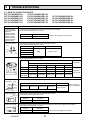
SPLIT-TYPE, HEAT PUMP AIR CONDITIONERS
December 2012
TECHNICAL & SERVICE MANUAL
R410A
Indoor unit
[Model names]
PLFY-P15VCM-E2
PLFY-P20VCM-E2
PLFY-P25VCM-E2
PLFY-P32VCM-E2
PLFY-P40VCM-E2
[Service Ref.]
PLFY-P15VCM-E2.TH
PLFY-P15VCM-E2R1.TH
PLFY-P20VCM-E2.TH
PLFY-P20VCM-E2R1.TH
PLFY-P20VCM-E2R2.TH
PLFY-P25VCM-E2.TH
PLFY-P25VCM-E2R1.TH
PLFY-P25VCM-E2R2.TH
PLFY-P32VCM-E2.TH
PLFY-P32VCM-E2R1.TH
PLFY-P32VCM-E2R2.TH
PLFY-P40VCM-E2.TH
PLFY-P40VCM-E2R1.TH
PLFY-P40VCM-E2R2.TH
No.OCH463
REVISED EDITION-C
R407C
R22
Revision:
• PLFY-P15VCM-E2R1.TH and
PLFY-P20/25/32/40VCM-E2R2.TH
have been added in REVISED
EDITION-C.
• Some descriptions have been
modified.
• Please void OCH463
REVISED EDITION-B.
Note:
• This manual describes only service
data of the indoor units.
• RoHS compliant products have
<G> mark on spec name plate.
CONTENTS
Model name
indication
INDOOR UNIT
1. TECHNICAL CHANGES......................... 2
2. SAFETY PRECAUTION..........................2
3. PART NAMES AND FUNCTIONS.......... 6
4. SPECIFICATIONS.................................14
5. 4-WAY AIR FLOW SYSTEM................. 16
6. OUTLINES AND DIMENSIONS............ 18
7. WIRING DIAGRAM............................... 19
8. REFRIGERANT SYSTEM DIAGRAM...... 21
9. TROUBLESHOOTING.......................... 22
10. DISASSEMBLY PROCEDURE............. 29
PARTS CATALOG (OCB463)
1
TECHNICAL CHANGES
PLFY-P15VCM-E2.TH
PLFY-P20VCM-E2R1.TH
PLFY-P25VCM-E2R1.TH
PLFY-P32VCM-E2R1.TH
PLFY-P40VCM-E2R1.TH
PLFY-P15VCM-E2R1.TH
PLFY-P20VCM-E2R2.TH
PLFY-P25VCM-E2R2.TH
PLFY-P32VCM-E2R2.TH
PLFY-P40VCM-E2R2.TH
• INDOOR CONTROLLER BOARD has been changed. (S/W version up)
PLFY-P20VCM-E2.TH
PLFY-P25VCM-E2.TH
PLFY-P32VCM-E2.TH
PLFY-P40VCM-E2.TH
PLFY-P20VCM-E2R1.TH
PLFY-P25VCM-E2R1.TH
PLFY-P32VCM-E2R1.TH
PLFY-P40VCM-E2R1.TH
• TURBO FAN has been changed.
2
SAFETY PRECAUTION
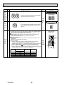
CAUTIONS RELATED TO NEW REFRIGERANT
Cautions for units utilizing refrigerant R407C
Do not use the existing refrigerant piping.
Do not use a refrigerant other than R407C.
The old refrigerant and lubricant in the existing piping
contain a large amount of chlorine which may cause the
lubricant deterioration of the new unit.
If another refrigerant (R22, etc.) is used, the chlorine in the
refrigerant may cause the lubricant deterioration.
Use “low residual oil piping”
If there is a large amount of residual oil (hydraulic oil, etc.)
inside the piping and joints, deterioration of the lubricant
will result.
Store the piping indoors, and both ends of the
piping sealed until just before brazing.
(Leave elbow joints, etc. in their packaging.)
If dust, dirt, or water enters the refrigerant cycle,
deterioration of the oil and compressor trouble may result.
Use ESTR , ETHER or HAB as the lubricant to
coat flares and flange connection parts.
If large amount of mineral oil enters, that can cause
deterioration of refrigerant oil etc.
Use liquid refrigerant to charge the system.
Use a vacuum pump with a reverse flow check valve.
The vacuum pump oil may flow back into the refrigerant
cycle and cause the lubricant deterioration.
Use the specified refrigerant only.
Never use any refrigerant other than that specified.
Doing so may cause a burst, an explosion, or fire when the
unit is being used, serviced, or disposed of.
Correct refrigerant is specified in the manuals and on the
spec labels provided with our products.
We will not be held responsible for mechanical failure,
system malfunction, unit breakdown or accidents caused
by failure to follow the instructions.
Ventilate the room if refrigerant leaks during
operation. If refrigerant comes into contact with
a flame, poisonous gases will be released.
If gas refrigerant is used to seal the system, the composition
of the refrigerant in the cylinder will change and performance
may drop.
OCH463C
2
[1] Cautions for service
· After recovering the all refrigerant in the unit, proceed to working.
· Do not release refrigerant in the air.
· After completing the repair service, recharge the cycle with the specified amount of liquid refrigerant.
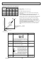
[2] Refrigerant recharging
(1) Refrigerant recharging process
1Direct charging from the cylinder.
· R407C cylinder available on the market has a syphon pipe.
· Leave the syphon pipe cylinder standing and recharge it.
(By liquid refrigerant)
Unit
Gravimeter
(2) Recharge in refrigerant leakage case
· After recovering the all refrigerant in the unit, proceed to working.
· Do not release the refrigerant in the air.
· After completing the repair service, recharge the cycle with the specified amount of liquid refrigerant.
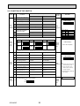
[3] Service tools
Use the below service tools as exclusive tools for R407C refrigerant.
No.
Tool name
Specifications
1
Gauge manifold
2
Charge hose
3
Electronic scale
· Only for R407C
· Use the existing fitting SPECIFICATIONS. (UNF7/16)
· Use high-tension side pressure of 3.43MPa·G or over.
· Only for R407C
· Use pressure performance of 5.10MPa·G or over.
—
4
Gas leak detector
· Use the detector for R134a or R407C.
5
Adaptor for reverse flow check
· Attach on vacuum pump.
6
Refrigerant charge base
7
Refrigerant cylinder
8
Refrigerant recovery equipment
—
· For R407C
· Top of cylinder (Brown)
· Cylinder with syphon
OCH463C
3
—
Cautions for units utilizing refrigerant R410A
Do not use the existing refrigerant piping.
The old refrigerant and lubricant in the existing piping
contains a large amount of chlorine which may cause the
lubricant deterioration of the new unit.
Use the following tools specifically designed for
use with R410A refrigerant.
The following tools are necessary to use R410A refrigerant.
Gauge manifold
Charge hose
Gas leak detector
Torque wrench
Use “low residual oil piping”
If there is a large amount of residual oil (hydraulic oil, etc.)
inside the piping and joints, deterioration of the lubricant
will result.
Tools for R410A
Flare tool
Size adjustment gauge
Vacuum pump adaptor
Electronic refrigerant
charging scale
Handle tools with care.
Store the piping indoors, and both ends of the
piping sealed until just before brazing.
(Leave elbow joints, etc. in their packaging.)
If dirt, dust or moisture enters into refrigerant cycle, that can
cause deterioration of refrigerant oil or malfunction of compressor.
If dirt, dust or moisture enters into refrigerant cycle, that can
cause deterioration of refrigerant oil or malfunction of compressor.
Do not use a charging cylinder.
The refrigerant oil applied to flare and flange
connections must be ester oil, ether oil or
alkylbenzene oil in a small amount.
If large amount of mineral oil enters, that can cause deterioration of refrigerant oil etc.
Charge refrigerant from liquid phase of gas
cylinder.
If the refrigerant is charged from gas phase, composition
change may occur in refrigerant and the efficiency will be
lowered.
Do not use refrigerant other than R410A.
If other refrigerant (R22 etc.) is used, chlorine in refrigerant can cause deterioration of refrigerant oil etc.
If a charging cylinder is used, the composition of refrigerant will change and the efficiency will be lowered.
Use the specified refrigerant only.
Never use any refrigerant other than that specified.
Doing so may cause a burst, an explosion, or fire when the
unit is being used, serviced, or disposed of.
Correct refrigerant is specified in the manuals and on the
spec labels provided with our products.
We will not be held responsible for mechanical failure,
system malfunction, unit breakdown or accidents caused
by failure to follow the instructions.
Ventilate the room if refrigerant leaks during
operation. If refrigerant comes into contact with
a flame, poisonous gases will be released.
Use a vacuum pump with a reverse flow check
valve.
Vacuum pump oil may flow back into refrigerant cycle and
that can cause deterioration of refrigerant oil etc.
OCH463C
4
[1] Cautions for service
(1) Perform service after recovering the refrigerant left in unit completely.
(2) Do not release refrigerant in the air.
(3) After completing service, charge the cycle with specified amount of refrigerant.
(4) When performing service, install a filter drier simultaneously.
Be sure to use a filter drier for new refrigerant.
[2] Additional refrigerant charge
When charging directly from cylinder
· Check that cylinder for R410A on the market is syphon type.
· Charging should be performed with the cylinder of syphon standing vertically. (Refrigerant is charged from liquid phase.)
Unit
Gravimeter
[3] Service tools
Use the below service tools as exclusive tools for R410A refrigerant.
No.
Tool name
1
Gauge manifold
2
Charge hose
3
4
5
6
Electronic scale
Gas leak detector
Adaptor for reverse flow check
Refrigerant charge base
7
Refrigerant cylinder
8
Refrigerant recovery equipment
OCH463C
Specifications
· Only for R410A
· Use the existing fitting specifications. (UNF1/2)
· Use high-tension side pressure of 5.3MPa·G or over.
· Only for R410A
· Use pressure performance of 5.09MPa·G or over.
· Use the detector for R134a, R407C or R410A.
· Attach on vacuum pump.
· Only for R410A
· Cylinder with syphon
5
· Top of cylinder (Pink)
3
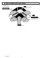
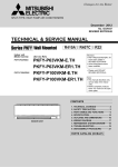
PART NAMES AND FUNCTIONS
3-1. Indoor Unit
Filter
Removes dust and pollutants
from inhaled air.
Horizontal Air Outlet
Sets horizontal airflow automatically
during cooling or dehumidifying.
Grille
Auto Air Swing Vane
Disperses airflow up and
down and adjusts the angle
of airflow direction.
Air Intake
Draws in air from room.
OCH463C
6
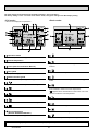
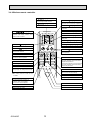
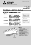
3-2. WIRED REMOTE CONTROLLER <PAR-30MAA/PAR-31MAA>
Wired remote controller function
* The functions which can be used are restricted according to the model.
Function
Body
: Supported
PAR-30MAA/PAR-31MAA
Slim
Product size H × W × D (mm)
LCD
: Unsupported
PAR-21MAA
City multi
120 × 120 × 19
120 × 130 × 19
Full Dot LCD
Partial Dot LCD
Backlight
Energy-saving
Energy-saving operation schedule
Automatic return to the preset temperature
Restriction
Setting the temperature range restriction
Function
Operation lock function
Weekly timer
On / Off timer
High Power
Manual vane angle
The functions of the function buttons change depending on
the screen. Refer to the button function guide that appears
at the bottom of the LCD for the functions they serve on a
given screen.
When the system is centrally controlled, the button function
guide that corresponds to the locked button will not appear.
<Main display>
<Main menu>
Fri
Room
Cool
Set temp.
Auto
Mode
Temp.
Fan
Function buttons
F1
F2
F3
Main menu
Vane·Louver·Vent. (Lossnay)
High power
Timer
Weekly timer
OU silent mode
Main display:
Cursor
Page
Function guide
F4
ON / OFF lamp
ON / OFF button
This lamp lights up in green while the unit is in operation.
It blinks while the remote controller is starting up or when
there is an error.
Press to turn ON/OFF the indoor unit.
SELECT button
Press to save the setting.
Function button F1
RETURN button
Main display : Press to change the operation mode.
Main menu : Press to move the cursor down.
Press to return to the previous screen.
Function button F2
MENU button
Main display : Press to decrease temperature.
Main menu : Press to move the cursor up.
Press to bring up the Main menu.
Backlit LCD
Operation settings will appear.
When the backlight is off, pressing any button turns the
backlight on and it will stay lit for a certain period of time
depending on the screen.
When the backlight is off, pressing any button turns
the backlight on and does not perform its function.
(except for the
(ON / OFF) button)
OCH463C
Main
7
Function button F3
Main display : Press to increase temperature.
Main menu : Press to go to the previous page.
Function button F4
Main display : Press to change the fan speed.
Main menu : Press to go to the next page.
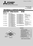
The main display can be displayed in two different modes: "Full" and "Basic".
The factory setting is "Full". To switch to the "Basic" mode, change the setting on the Main display setting.
<Full mode>
<Basic mode>
* All icons are displayed for explanation.
Fri
Fri
Cool
Room
Cool
Set temp.
Mode
Temp.
Set temp.
Auto
Auto
Mode
Fan
Temp.
Fan
Operation mode
Indoor unit operation mode appears here.
Appears when the buttons are locked.
Preset temperature
Preset temperature appears here.
Clock (See the Installation Manual.)
Appears when the On/Off timer or Night setback function is
enabled.
Current time appears here.
Fan speed
Fan speed setting appears here.
Appears when the Weekly timer is enabled.
Button function guide
Functions of the corresponding buttons appear here.
Appears while the units are operated in the energy-save
mode.
Appears when the ON/OFF operation is centrally controlled.
Appears when the operation mode is centrally controlled.
Appears when the built-in thermistor on the remote controller is activated to monitor the room temperature.
appears when the thermistor on the indoor unit is activated to monitor the room temperature.
Appears when the preset temperature is centrally controlled.
Indicates the vane setting.
Appears when the f lter reset function is centrally controlled.
Indicates the louver setting.
Indicates when f lter needs maintenance.
Room temperature
(See the Installation Manual.)
Indicates the ventilation setting.
Current room temperature appears here.
Appears when the preset temperature range is restricted.
Most settings (except ON / OFF, mode, fan speed, temperature) can be made from the Menu screen.
OCH463C
8
Menu structure
Main menu
Press the MENU button.
Move the cursor to the desired item with the
F1
and
F2
buttons, and press the SELECT button.
Vane · Louver · Vent. (Lossnay)
High power
Timer
On / Off timer
Auto-Off timer
Filter information
Error information
Weekly timer
Energy saving
Auto return
Schedule
Night setback
Restriction
Temp. range
Operation lock
Maintenance
Auto descending panel
Manual vane angle
Initial setting
Main / Sub
Clock
Main display
Contrast
Display details
Auto mode
Administrator password
Language selection
Service
Service menu
Test run
Drain pump test run
Input maintenance info.
Function setting
Lossnay (City Multi only)
Check
Self check
Maintenance password
Remote controller check
Not all functions are available on all models of indoor units.
OCH463C
9
Main menu list
Setting and display items
Setting details
Vane · Louver · Vent.
(Lossnay)
Use to set the vane angle.
• Select a desired vane setting from f ve different settings.
Use to turn ON / OFF the louver.
• Select a desired setting from "ON" and "OFF."
Use to set the amount of ventilation.
• Select a desired setting from "Off," "Low," and "High."
High power
Use to reach the comfortable room temperature quickly.
• Units can be operated in the High-power mode for up to 30 minutes.
Timer
On/Off timer
Use to set the operation On/Off times.
• Time can be set in 5-minute increments.
* Clock setting is required.
Auto-Off
timer
Use to set the Auto-Off time.
• Time can be set to a value from 30 to 240 in 10-minute increments.
Filter information
Use to check the f lter status.
• The f lter sign can be reset.
Error information
Use to check error information when an error occurs.
• Error code, error source, refrigerant address, unit model, manufacturing number, contact
information (dealer's phone number) can be displayed.
* The unit model, manufacturing number, and contact information need to be registered in
advance to be displayed.
Weekly timer
Use to set the weekly operation On / Off times.
• Up to eight operation patterns can be set for each day.
* Clock setting is required.
* Not valid when the On/Off timer is enabled.
Energy
saving
Auto return
Use to get the units to operate at the preset temperature after performing energy-save
operation for a specif ed time period.
• Time can be set to a value from 30 and 120 in 10-minute increments.
* This function will not be valid when the preset temperature ranges are restricted.
Schedule
Set the start/stop times to operate the units in the energy-save mode for each day of the
week, and set the energy-saving rate.
• Up to four energy-save operation patterns can be set for each day.
• Time can be set in 5-minute increments.
• Energy-saving rate can be set to a value from 0% or 50 to 90% in 10% increments.
* Clock setting is required.
Night setback
Restriction
Use to make Night setback settings.
• Select "Yes" to enable the setting, and "No" to disable the setting. The temperature range and
the start/stop times can be set.
* Clock setting is required.
Temp. range
Use to restrict the preset temperature range.
• Different temperature ranges can be set for different operation modes.
Operation
lock
Use to lock selected functions.
• The locked functions cannot be operated.
Maintenance Auto
descending
panel
Manual
vane angle
Initial setting Main/Sub
Clock
Auto descending panel (Optional parts) Up / Down you can do.
Use to set the vane angle for each vane to a f xed position.
When connecting two remote controllers, one of them needs to be designated as a sub
controller.
Use to set the current time.
Main display Use to switch between "Full" and "Basic" modes for the Main display.
• The default setting is "Full."
Contrast
OCH463C
Use to adjust screen contrast.
10
Setting and display items
Initial setting Display
details
Auto mode
Setting details
Make the settings for the remote controller related items as necessary.
Clock: The factory settings are "Yes" and "24h" format.
Temperature: Set either Celsius (°C) or Fahrenheit (°F).
Room temp. : Set Show or Hide.
Auto mode: Set the Auto mode display or Only Auto display.
Whether or not to use the AUTO mode can be selected by using the button.
This setting is valid only when indoor units with the AUTO mode function are connected.
Administrator The administrator password is required to make the settings for the following items.
password
• Timer setting • Energy-save setting • Weekly timer setting
• Restriction setting • Outdoor unit silent mode setting • Night set back
Service
Language
selection
Test run
Use to select the desired language.
Select "Test run" from the Service menu to bring up the Test run menu.
• Test run • Drain pump test run
Input
Select "Input maintenance Info." from the Service menu to bring up the Maintenance
maintenance information screen.
The following settings can be made from the Maintenance Information screen.
• Model name input • Serial No. input • Dealer information input
Function
Make the settings for the indoor unit functions via the remote controller as necessary.
setting
This setting is required only when the operation of City Multi units is interlocked with
LOSSNAY
LOSSNAY units.
setting
(City Multi only)
Check
Error history: Display the error history and execute delete error history.
Refrigerant leak check: Refrigerant leaks can be judged.
Smooth maintenance: The indoor and outdoor maintenance data can be displayed.
Request cord: Details of the operation data including each thermistor temperature and error
history can be checked.
Self check
Error history of each unit can be checked via the remote controller.
Maintenance Take the following steps to change the maintenance password.
password
Remote
When the remote controller does not work properly, use the remote controller checking
controller
function to troublushoot the problem.
check
OCH463C
11
3-3. WIRED REMOTE CONTROLLER <PAR-21MAA>
“Sensor” indication
Display Section
For purposes of this explanation,
all parts of the display are shown.
During actual operation, only
the relevant items will be lit.
Identifies the current operation
Displayed when the remote controller
sensor is used.
Day-of-Week
Shows the current day of the week.
Time/Timer Display
“Locked” indicator
Shows the current time, unless the simple or Auto Off
timer is set.
If the simple or Auto Off timer is set, the time to be
switched off is shown.
Indicates that remote controller buttons have been locked.
“Clean The Filter” indicator
Shows the operating mode, etc.
*Multilanguage display is available.
To be displayed on when it is time to
clean the filter.
TIME SUN MON TUE WED THU FRI SAT
TIMER
Hr
ON
AFTER
Indicates that operation from the
remote controller has been prohibited by a master controller.
“Timer is Off” indicator
Indicates that the timer is off.
WEEKLY
SIMPLE
AUTO OFF
ONLY1Hr.
Shows the target temperature.
The indicator comes on if the corresponding timer is set.
Fan Speed indicator
Shows the selected fan speed.
Up/Down Air Direction indicator
The indicator
shows the direction of the outcoming airflow.
“One Hour Only” indicator
Temperature Setting
FUNCTION
FILTER
°F°C
°F°C
“Centrally Controlled” indicator
Timer indicators
AFTER OFF
ERROR CODE
Displayed if the airflow is set to
low or downward during COOL
or DRY mode. (Operation varies
according to model.)
The indicator goes off in 1 hour,
when the airflow direction
also changes.
Room Temperature display
Shows the room temperature. The room
temperature display range is 8 – 39.
The display blinks if the temperature
is less than 8 or 39 or more.
Ventilation indicator
Appears when the unit is running in
Ventilation mode.
Louver display
Indicates the action of the swing louver.
Does not appear if the louver is not
running.
(Power On indicator)
Indicates that the power is on.
Operation Section
ON/OFF button
Temperature setting buttons
Down
Fan Speed button
Up
Timer Menu button
(Monitor/Set button)
Filter
button
(<Enter> button)
Mode button (Return button)
TEMP.
ON/OFF
Set Time buttons
Check button (Clear button)
Back
Ahead
Timer On/Off button
(Set Day button)
Test Run button
MENU
BACK
PAR-21MAA
MONITOR/SET
ON/OFF
FILTER
DAY
CHECK TEST
OPERATION
CLOCK
CLEAR
Airflow Up/Down button
Louver button
(
Operation button)
To return operation
number
Opening the
cover
Built-in temperature sensor
Ventilation button
( Operation button)
To go to next operation
number
Note:
L “PLEASE WAIT” message
This message is displayed for approximately 3 minutes when power is supplied to the indoor unit or when the unit is recovering from a power failure.
L “NOT AVAILABLE” message
This message is displayed if an invalid button is pressed (to operate a function that the indoor unit does not have).
If a single remote controller is used to operate multiple indoor units simultaneously that are different types, this message will not be displayed as
far as any of the indoor units is equipped with the function.
OCH463C
12
3-4. Wireless remote controller
CHECK TEST RUN display
CHECK and TEST RUN display indicate that
the unit is being checked or test-run.
MODEL SELECT display
display
Lights up while the signal is transmitted to
the indoor unit when the button is pressed.
display
Blinks when model is selected.
SET TEMP. display indicates the set desired
temperature.
CLOCK display
display
Displays the current time.
OPERATION MODE display
Operation mode display indicates which
operation mode is in effect.
TIMER display
CHECK TEST RUN
MODEL SELECT
°C
AMPM
AMPM
display
The vertical direction of air flow is indicated.
NOT AVAILABLE
ON/OFF
FAN SPEED SELECT button
Used to change the fan speed.
MODE SELECT button
” display
Displays the order of timer operation.
”“
” display
buttons
MODE
FAN
AUTO STOP
VANE
AUTO START
CHECK LOUVER
TEST RUN
SET
h
min
RESET
Used to switch the operation mode between
cooling, drying, fan, heating and auto mode.
SET TEMPERATURE button sets any desired
room temperature.
TIMER CONTROL buttons
AUTO STOP (OFF timer): when this switch is
set, the air conditioner will be automatically
stopped at the preset time.
AUTO START (ON timer): when this switch is
set, the air conditioner will be automatically
started at the preset time.
CLOCK
h and min buttons
Buttons used to set the “hour and minute” of
the current time and timer settings.
In case the outdoor unit is cool only type,
the heating and auto mode are not
available.
LOUVER button
Changes left/right airflow direction.
CHECK-TEST RUN buttons
(Not available for this model.)
Only press this button to perform an
inspection check or test operation.
Do not use it for normal operation.
CLOCK button
RESET button
VANE CONTROL button
SET button
Used to change the air flow
OCH463C
”“
Displays whether timer is on or off.
display
The unit is turned ON and OFF alternately
each time the button is pressed.
“
“
TEMP
FAN SPEED display indicates which fan
speed has been selected.
ON/OFF button
Displays when in timer operation or when
setting timer.
13
4
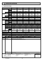
SPECIFICATIONS
4-1. SPECIFICATIONS
Model
PLFY-P15VCM-E2
PLFY-P20VCM-E2
PLFY-P25VCM-E2
PLFY-P32VCM-E2
PLFY-P40VCM-E2
Single phase 220-230-240V 50Hz
2.2
2.8
3.6
4.5
1.7
1 kW
1,900
2,400
3,100
3,900
1,450
1 kcal / h
7,500
9,600
12,300
15,400
5,800
1 Btu / h
2 kcal / h
2,000
2,500
3,150
4,000
1,500
Power input
0.05
0.05
0.06
0.06
0.04
kW
Current input A
0.23
0.23
0.28
0.28
0.19
3 kW
2.5
3.2
4.0
5.0
1.9
Heating capacity
3 kcal / h
2,200
2,800
3,400
4,300
1,600
(Nominal )
3 Btu / h
8,500
10,900
13,600
17,100
6,500
Power input
0.05
0.05
0.06
0.06
0.04
kW
Current input A
0.23
0.23
0.28
0.28
0.19
Unit: Galvanized sheets with grey heat insulation
External finish
208 × 570 × 570
208 × 570 × 570
208 × 570 × 570
208 × 570 × 570
208 × 570 × 570
mm
External dimension
H×W×D
8-1/4" × 22-1/2" × 22-1/2" 8-1/4" × 22-1/2" × 22-1/2" 8-1/4" × 22-1/2" × 22-1/2" 8-1/4" × 22-1/2" × 22-1/2" 8-1/4" × 22-1/2" × 22-1/2"
in.
15.5 (35)
15.5 (35)
15.5 (35)
17 (38)
17 (38)
kg (lb)
Net weight
SLP-2AAW or SLP-2ALW SLP-2AAW or SLP-2ALW SLP-2AAW or SLP-2ALW SLP-2AAW or SLP-2ALW SLP-2AAW or SLP-2ALW
Decoration Model
panel
External finish
White Munsell(6.4Y 8.9/0.4)
Dimension
20 × 650 × 650
20 × 650 × 650
20 × 650 × 650
20 × 650 × 650
20 × 650 × 650
mm
H×W×D
13/16" × 25-5/8" × 25-5/8" 13/16" × 25-5/8" × 25-5/8" 13/16" × 25-5/8" × 25-5/8" 13/16" × 25-5/8" × 25-5/8" 13/16" × 25-5/8" × 25-5/8"
in.
Net Weight
3 (7)
3 (7)
3 (7)
3 (7)
3 (7)
kg (lb)
Cord heater
0.015
0.015
0.015
0.015
0.015
kW
Cross fin (Aluminum fin and copper tube)
Heat exchanger
Type × Quantity
Turbo fan × 1
FAN
External static press.
0 Pa (0 mmH2O)
0 Pa (0 mmH2O)
0 Pa (0 mmH2O)
0 Pa (0 mmH2O)
0 Pa (0 mmH2O)
Motor type
Single phase induction motor
Motor output kW
0.008
0.011
0.015
0.02
0.02
Driving mechanism
Direct-driven by motor
Airflow rate
8-8.5-9
8-9-10
8-9-10
8-9-11
8-9-11
m3 / min
(Low-Mid-High) L / s
133-142-150
133-150-167
133-150-167
133-150-183
133-150-183
283-300-353
283-318-353
283-318-353
283-318-388
283-318-388
cfm
Noise level (Low-Mid-High) dB <A>
28-30-31
28-31-35
29-31-37
29-33-38
30-34-39
(measured in anechoic room)
Polyethylene foam
Insulation material
PP honeycomb fabric (long life type)
Air filter
Fuse
Protection device
LEV
Refrigerant control device
R410A, R407C, R22 CITY MULTI
Connectable outdoor unit
ø6.35 (ø1/4") Flare
ø6.35 (ø1/4") Flare
ø6.35 (ø1/4") Flare
ø6.35 (ø1/4") Flare
ø6.35 (ø1/4") Flare
mm (in.)
Diameter of Liquid
ø12.7 (ø1/2") Flare
ø12.7 (ø1/2") Flare
ø12.7 (ø1/2") Flare
ø12.7 (ø1/2") Flare
ø12.7 (ø1/2") Flare
mm (in.)
refrigerant pipe Gas
O.D. 32mm (1-1/4") (PVC pipe VP-25 connectable)
mm (in.)
Field drain pipe size
Document
Installation manual, Instruction book
Standard
Drain hose I.D. 32mm (1-1/4"), Wireless junction cable
attachment Accessory
Optional parts
Decoration panel : SLP-2AAW or SLP-2ALW
Remark
*PLFY-P-VCM-E2 should use together with Decoration panel.
Power source
Cooling capacity
(Nominal)
Installation
Note :
Details on foundation work, duct work, insulation work, electrical wiring, power source switch, and other items shall be referred to
the Installation Manual.
1 Nominal cooling condition
Indoor :
Outdoor :
Pipe length :
Level difference :
27°CDB/19°CWB (81°FDB/66°FWB)
35°CDB (95°FDB)
7.5 m (24-9/16 ft)
0 m (0 ft)
2 Nominal cooling condition
3 Nominal heating condition
27°CDB/19.5°CWB (81°FDB/67°FWB)
35°CDB (95°FDB)
5 m (16-3/8 ft)
0 m (0 ft)
* Nominal conditions 1, 3 are subject to JIS B8615-1.
* Due to continuing improvement, above specification may be subject to change without notice.
OCH463C
14
20°CDB (68°FDB)
7°CDB/6°CWB (45°FDB/43°FWB)
7.5 m (24-9/16 ft)
0 m (0 ft)
Unit converter
kcal
Btu/h
cfm
lb
= kW × 860
= kW × 3,412
= m3/min x 35.31
= kg / 0.4536
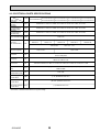
4-2. ELECTRICAL PARTS SPECIFICATIONS
Service ref.
Parts name
Thermistor
(Room temperature
detection)
Thermistor
(Pipe temperature
detection/ Liquid)
Thermistor
(Pipe temperature
detection/ Gas)
Symbol
PLFY-P20VCM-E2.TH PLFY-P25VCM-E2.TH PLFY-P32VCM-E2.TH PLFY-P40VCM-E2.TH
PLFY-P15VCM-E2.TH
PLFY-P20VCM-E2R1.TH PLFY-P25VCM-E2R1.TH PLFY-P32VCM-E2R1.TH PLFY-P40VCM-E2R1.TH
PLFY-P15VCM-E2R1.TH
PLFY-P20VCM-E2R2.TH PLFY-P25VCM-E2R2.TH PLFY-P32VCM-E2R2.TH PLFY-P40VCM-E2R2.TH
TH21
Resistance 0/15k, 10/9.6k, 20/6.3k, 25/5.4k, 30/4.3k, 40/3.0k
TH22
Resistance 0/15k, 10/9.6k, 20/6.3k, 25/5.4k, 30/4.3k, 40/3.0k
TH23
Resistance 0/15k, 10/9.6k, 20/6.3k, 25/5.4k, 30/4.3k, 40/3.0k
Fuse
(Indoor controller board) FUSE
Fan motor
(with Thermal fuse)
MF
Fan motor capacitor
C
250V 6.3A
6-pole OUTPUT 8W 6-pole OUTPUT 11W 6-pole OUTPUT 15W 6-pole OUTPUT 20W 6-pole OUTPUT 20W
PK6V8-LA
PK6V11-LF
PK6V15-LD
PK6V20-LL
PK6V20-LM
Thermal fuse
OFF 145 $ 2
1.0 × 440V
1.5 × 440V
Vane motor
MV
MSBPC20M13
DC12V 300/phase
Drain pump
DP
PLD-12230ME-1
INPUT 12/10.8W 241/Hr
Drain sensor
DS
Thermistor resistance 0/6k, 10/3.9k, 20/2.6k, 25/2.2k, 30/1.8k, 40/1.3k
Linear expansion valve
[coil]
LEV
DC12V Stepping motor drive, Port dimension :5.2 (0~2000pulse)
EDM-40YGME
Electric heater
(Condensation proof)
H2
240V 15W
Power supply
terminal block
TB2
(L, N, ) Rated to 330V 30A *
Transmission
terminal block
TB5
(M1, M2, S) Rated to 250V 20A *
MA remote controller
terminal block
TB15
(1, 2) Rated to 250V 10A *
* Note: Refer to WIRING DIAGRAM for the supplied voltage.
OCH463C
15
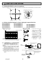
5
4-WAY AIR FLOW SYSTEM
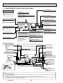
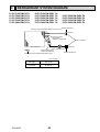
5-1. FRESH AIR INTAKE (Location for installation)
At the time of installation, use the duct holes (cut out) located at the positions shown in following diagram, as and when required.
Fresh air intake
Detail drawing of fresh air intake
25
:100
:73.4
Cut out hole
0°
12
12
0°
118
3-:2.8 hole
Burring hole
Ceiling surface
Refrigerant pipe
Electrical Box
Drain pipe
5-2. FRESH AIR INTAKE AMOUNT & STATIC PRESSURE CHARACTERISTICS
PLFY-P15VCM-E2.TH
PLFY-P20VCM-E2.TH
PLFY-P25VCM-E2.TH
PLFY-P32VCM-E2.TH
PLFY-P40VCM-E2.TH
PLFY-P15VCM-E2R1.TH
PLFY-P20VCM-E2R1.TH
PLFY-P25VCM-E2R1.TH
PLFY-P32VCM-E2R1.TH
PLFY-P40VCM-E2R1.TH
Taking air into the unit
How to read curves
3.0
Air flow : Q [m
3.5
0
Q
-50
-100
Q…Designed amount of fresh air intake
<m3/min>
A…Static pressure loss of fresh air
intake duct system with air flow
amount Q
<Pa>
…
B Forced static pressure at air conditioner inlet with air flow amount Q
<Pa>
C…Static pressure of booster fan with
air flow amount Q
<Pa>
D … Static pressure loss increase
amount of fresh air intake duct system for air flow amount Q
<Pa>
E…Static pressure of indoor unit with
air flow amount Q
<Pa>
Qa…Estimated amount of fresh air
intake without D
<m3/min>
Duct characteristics
at site
A
2.5
Curve in the
left graphs
C
2.0
1
3/min]
B
Static pressure : P [Pa]
50
0.5 1.0 1.5
0
PLFY-P20VCM-E2R2.TH
PLFY-P25VCM-E2R2.TH
PLFY-P32VCM-E2R2.TH
PLFY-P40VCM-E2R2.TH
2
E
C
A
-150
-200
Q
-250
3
5-3. OPERATION IN CONJUNCTION
WITH DUCT FAN (Booster fan)
• Whenever the indoor unit operates, the duct fun also
operates.
(1) Connect the optional multiple remote controller
adapter (PAC-SA88HA-E) to the connector CN51
on the indoor controller board.
(2) Drive the relay after connecting the 12V DC relay
between the Yellow and Orange connector wires.
MB: Electromagnetic switch power relay for duct fan.
X: Auxiliary relay (For DC 12V, coil rating : 1.0W or
below)
A
D
-300
NOTE: Fresh air intake amount should be 20% or less of
whole air amount to prevent dew dripping.
Q
Qa
CN51
on indoor
controller board
5
Green
Indoor unit side
Indoor controller board
Red
Brown
CN51
MB
Orange
Multiple remote
controller adapter
PAC-SA88HA-E
CN51
16
~
Yellow
1
Connector (5P)
Multiple remote
controller adapter
PAC-SA88HA-E
OCH463C
Be sure to secure insulation
material by tape, etc.
Installation at site
Be sure to secure insulation
material by tape, etc.
Distance between indoor
controller board and relay
must be within 10m.
5-4. FIXING HORIZONTAL VANE
Horizontal vane of each air outlet can be fixed according to the environment where it is installed.
Setting procedure
1) Turn off a main power supply (Turn off a breaker).
2) Disconnect the vane motor connector of the direction of the arrow with pressing the unlocking button as shown in figure
below.
Insulate the disconnected connector with the plastic tape.
Vane motor
Vane motor
Connector
Unlocking button
Horizontal vane
3) Set a vertical vane of the air outlet, which is to be fixed by the hand slowly within the range in the table below.
Measured standard
position of the grille
Horizontal vane
<Set range>
Standard of
horizontal position
Level 30°
(Min.)
Downward 45°
Downward 55°
Downward 70°
(Max.)
Dimension A (mm)
21
25
28
30
+ Dimension between 21 mm and 30 mm can be arbitrarily set.
Caution
OCH463C
Do not set the dimension out of the range.
Erroneous setting could cause dew drips, smudge on ceiling or malfunction of unit.
17
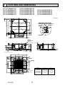
6
OUTLINES AND DIMENSIONS
PLFY-P15VCM-E2.TH
PLFY-P20VCM-E2.TH
PLFY-P25VCM-E2.TH
PLFY-P32VCM-E2.TH
PLFY-P40VCM-E2.TH
PLFY-P15VCM-E2R1.TH
PLFY-P20VCM-E2R1.TH
PLFY-P25VCM-E2R1.TH
PLFY-P32VCM-E2R1.TH
PLFY-P40VCM-E2R1.TH
PLFY-P20VCM-E2R2.TH
PLFY-P25VCM-E2R2.TH
PLFY-P32VCM-E2R2.TH
PLFY-P40VCM-E2R2.TH
Detail drawing of fresh air intake
:100
25
3-:2.8
Burring hole
570
335
:73.4
Cut out hole
570
57
56
15~37
87
12
0
0
12
31
118
420
530
Suspension bolt pitch
Suspension bolt pitch
576~620
Ceiling hole
15~37
Unit: mm
Fresh air intake
Ceiling surface
199
352
335
576~620 Ceiling hole
15~37
15~37
Drain pipe
VP-25 connection
(O.D.:32)
2
17
202
230
Wiring entry
Suspension bolt M10 or W3/8
182
235
208
193
Ceiling surface
20
+5
0
Grille
Terminal block
Suspension bolt lower edge
27
38~58
48
93
121
66
1
650
301
Air outlet hole
Brand label
55 35
Grille
V/M
Drain hole
377
Auto vane
Air intake hole
Air outlet hole
301
650
V/M
Models
V/M
V/M
Air intake grille
Vane motor
35 55
OCH463C
377
Air intake hole
18
PLFY-P15VCM-E2
PLFY-P20VCM-E2
PLFY-P25VCM-E2
PLFY-P32VCM-E2
PLFY-P40VCM-E2
Refrigetant pipe Refrigetant pipe
(6.35mm dia.)
(12.7mm dia.)
flared connection flared connection
1/4 inch
1/2 inch
7
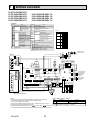
WIRING DIAGRAM
PLFY-P15VCM-E2.TH
PLFY-P20VCM-E2.TH
PLFY-P25VCM-E2.TH
PLFY-P32VCM-E2.TH
PLFY-P40VCM-E2.TH
PLFY-P20VCM-E2R1.TH
PLFY-P25VCM-E2R1.TH
PLFY-P32VCM-E2R1.TH
PLFY-P40VCM-E2R1.TH
[LEGEND]
SYMBOL
I.B
CN32
CN41
CN51
CN52
FUSE
SW1
SW2
SW3
SW4
SW11
SW12
SW14
SWE
X1
X4
X5
X6
X7
C1
DP
NAME
INDOOR CONTROLLER BOARD
CONNECTOR REMOTE SWITCH
JEMA HA TERMINAL-A
CENTRALLY CONTROL
REMOTE INDICATION
FUSE (T6.3AL 250V)
SWITCH MODE SELECTION
CAPACITY CODE
MODE SELECTION
MODEL SELECTION
ADDRESS SETTING 1s DIGIT
ADDRESS SETTING 10ths DIGIT
BRANCH No.
DRAIN PUMP (TEST MODE)
DRAIN PUMP/DEW PREVENTION HEATER
AUX.
RELAY
FAN MOTOR (LL)
FAN MOTOR (Lo)
FAN MOTOR (Hi)
FAN MOTOR (Me)
CAPACITOR (FAN MOTOR)
DRAIN PUMP
SYMBOL
DS
H2
LEV
MF
MV
TB2
TB5
TB15
TH21
NAME
DRAIN SENSOR
DEW PREVENTION HEATER
LINEAR EXPANSION VALVE
FAN MOTOR (WITH THERMAL FUSE)
VANE MOTOR
POWER SUPPLY
TERMINAL
TRANSMISSION
BLOCK
MA-REMOTE CONTROLLER
THERMISTOR ROOM TEMP. DETECTION
(0°C/15kΩ, 25°C/5.4kΩ)
<Fig. 1>
MODELS
PIPE TEMP. DETECTION / LIQUID
(0°C/15kΩ, 25°C/5.4kΩ)
TH22
TH23
P.B
OPTION PART
W.B
BZ
LED1
LED2
RU
SW1
SW2
PIPE TEMP. DETECTION / GAS
(0°C/15kΩ, 25°C/5.4kΩ)
INDOOR POWER BOARD
PCB FOR WIRELESS REMOTE CONTROLLER
BUZZER
LED (OPERATION INDICATOR: GREEN)
LED (PREPARATION FOR HEATING: ORANGE)
RECEIVING UNIT
EMERGENCY OPERATION (HEAT)
EMERGENCY OPERATION (COOL)
ON
OFF
P20
ON
OFF
P25
ON
OFF
P32
ON
OFF
P40
ON
OFF
CNB
BZ
SKY BLU
LED2
LED1
OFF ON
CN32
(WHT)
3
1
ON
OFF
SW2
4
SW3
SW4
1 2 34 5 5
YLW
YLW
WHT
RED
1
CNDK
(RED)
1
CN2D
(WHT)
LED1
CN90
(WHT)
CN60
(WHT)
1
2
1
CN2M
(BLU)
1 6
9
CN31
(WHT)
1
2
CN52
(GRN)
SW14
CN6V
(GRN)
F
6
1
1
5
9
012
BRANCH
No.
0 1
3
BLK
WHT
TB5
M1
M2
S
TB15
1
2
TO OUTDOOR UNIT
BC CONTROLLER
M-NET REMOTE
CONTROLLER
DC24-30V
TO MA-REMOTE
CONTROLLER
DC8.7-13V
LED2
CN20 CN21 CN29
(RED) (WHT) (BLK)
0 1
10ths
1s
DIGIT DIGIT
2
1 2
1 2
t°
t°
t°
1
6
M
For wireless grille type
SW12 SW11
1
CN3A
(BLU)
1
3
1
See Fig.1
RU
CNP
3 (BLU) 3
2 3
1 2 3 4 5 6 1 2 34 5 6 78910
ON
OFF
5
DC13.1V
CN2S
2 (WHT)
TRANS
X1
CN51
(WHT)
1
1
2 3
SW2
1 2 34 5 6 78910
CNC
(RED)
3
X7
CN41
(WHT)
SW1
CND
(ORN)
3
1
FUSE
250V 6.3A
1
3456
ON
OFF
SW1
X6 X5 X4
FAN
(WHT)
7 8 9
BRN
RED
ORN
YLW
9 BLU
VLT
GRY
PINK
1 3 5 7 9
POWER SUPPLY
~/N220-240V 50Hz
TO NEXT
INDOOR
UNIT
1
7 8 9
SWE
1
2
3
4
5
6
7
8
9
BC
MV
DE
I.B
FUSE BREAKER
(16A)
(16A)
PULL
BOX
3
BRN
RED
BLU
ORN
YLW
WHT
5
W.B
123456
CNSK
(RED) 3
1
RED
BLK
YLW
BRN
WHT
BLU
M
ORN
C1
M
1~
M
1~
JP16
JP17
J41
J42 Pair No.
MV
123456
P.B
DP
MF
7
6
3
2
1
9
78 A
M
RED
ORN
5 YLW
WHT
5
BLU
5
10
5
5 6
MV
YLW
YLW
4
M
123456
RED L
BLU
N
GRN/YLW
5 6
MV
123456
4
H2
5
123456
TB2
GRILLE
M
SW2
P15
t°
DS
TH21 TH22 TH23
LEV
Notes:
1.At servicing for outdoor unit, always follow the wiring diagram of outdoor unit.
2.In case of using MA-Remote controller, please connect to TB15.
(Remote controller wire is non-polar.)
3.In case of using M-NET, please connect to TB5. (Transmission line is non-polar.)
4.Symbol [S] of TB5 is the shield wire connection.
5.Symbols used in wiring diagram above are,
: terminal block,
: connecter.
6.The setting of the SW2 dip switches differs in the capacity. For the detail, refer to Fig.1.
OCH463C
19
LED on indoor board for service
Mark
Meaning
LED1
Main power supply
LED2
Power supply for
MA-Remote controller
Function
Main power supply (Indoor unit)
Power on → Iamp is lit
Power supply for MA-Remote controller
on → Iamp is lit
PLFY-P15VCM-E2R1.TH
PLFY-P20VCM-E2R2.TH
PLFY-P32VCM-E2R2.TH
PLFY-P25VCM-E2R2.TH
PLFY-P40VCM-E2R2.TH
LEGEND
CN51(WHT)
CN52(GRN)
SWE
W.B
CNB
BZ
BRN
RED
ORN
YLW
9 BLU
VLT
GRY
PINK
SKY BLU
1
2
3
4
5
6
7
8
9
OFF ON
CN32
(WHT)
3
ON
OFF
LED1
1 3 5 7 9
X6 X5 X4
CND
(ORN)
3
1
FUSE
250V 6.3A
1
ON
OFF
CNC
(RED)
X7
CN51 +2
(WHT)
1
5
SW4
1 2 34 5 5
1
CNP
3 (BLU) 3
1
TRANS
CNDK
(RED)
1
CN2D
(WHT)
1
CN60
(WHT)
9
1
CN52 +2
(GRN)
SW14
CN6V
(GRN)
1
6
F 012
1
BRN
RED
BLU
ORN
YLW
WHT
9
1
3
SW12 SW11
0 1
9
1
2
1
3
BLK
WHT
TB5
M1
M2
S
TB15
1
2
TO OUTDOOR UNIT
BC CONTROLLER
M-NET REMOTE
CONTROLLER
DC24-30V
TO MA-REMOTE
CONTROLLER
DC8.7-13V
LED2
CN20 CN21 CN29
(RED) (WHT) (BLK)
0 1
9
10ths
1s
DIGIT DIGIT
2
1 2
1 2
tº
tº
tº
1
6
5
See fig +1
BRANCH
No.
1
2
CN3A
(BLU)
CN31
(WHT)
6
1
1
CN2M
(BLU)
X1
CN90
(WHT)
DC13.1V
CN2S
2 (WHT)
1
LED1
SW2
RU
3
2 3
1 2 3456 1 2 34 5 6 78910
3
POWER SUPPLY
~/N220-240V 50Hz
TO NEXT
INDOOR
UNIT
P.B
2 3
ON
OFF
FAN
(WHT)
FUSE BREAKER
(16A)
(16A)
PULL
BOX
CNSK
(RED) 3
1
CN41 8
(WHT)
1 2 34 5 6 78910
4
SW3
SW2
123456
M
1~
CN100 +2
(WHT)
SW1
123456
DP
3456
SW1
RED
1
LED2
P40
ON
OFF
123456
WHT
RED
5
P32
ON
OFF
123456
RED L
BLU
N
GRN/YLW
M
1~
ORN
MV
ON
OFF
123456
TB2
MF
I.B
P25
In connecting optional IT terminal,
use either CN51 or CN52 which is
not connected.
Be careful for connector colors.
1
CN100(WHT)
5
1
C1
ON
OFF
7 8
M
5 4
CN100(WHT)
5 3
1
7
6
3
2
1
P20
7 8
MV
8
1
ON
OFF
YLW
YLW
M
IT terminal
PAC-IT52AD-E
1
5
D
BC E
MV
RED
ORN
5 YLW
WHT
5
BLU
5
PCB FOR WIRELESS REMOTE CONTROLLER
BUZZER
LED(OPERATION INDICATOR:GREEN)
LED(PREPARATION FOR HEATING : ORANGE)
RECEIVING UNIT
EMERGENCY OPERATION(HEAT)
EMERGENCY OPERATION(COOL)
BLK
YLW
BRN
WHT
BLU
M
5
10
5
P.B
OPTION PART
W.B
BZ
LED1
LED2
RU
SW1
SW2
JP16
JP17
J41
J42 Pair No.
M
MV
YLW
YLW
PIPE TEMP. DETECTION / GAS
(0ºC/15kΩ , 25ºC/5.4kΩ)
INDOOR POWER BOARD
789A
H2
TH23
SW2
P15
5 6
GRILLE
5 4
MODELS
PIPE TEMP. DETECTION / LIQUID
(0ºC/15kΩ , 25ºC/5.4kΩ)
TH22
IT terminal
PAC-IT51AD-E
1
5
8
The black square(■)indicates
a switch position. <+1>
4
+2
NAME
DRAIN SENSOR
DEW PREVENTION HEATER
LINEAR EXPANSION VALVE
FAN MOTOR (WITH THERMAL FUSE)
VANE MOTOR
POWER SUPPLY
TERMINAL
TRANSMISSION
BLOCK
MA-REMOTE CONTROLLER
THERMISTOR ROOM TEMP. DETECTION
(0ºC/15kΩ , 25ºC/5.4kΩ)
SYMBOL
DS
H2
LEV
MF
MV
TB2
TB5
TB15
TH21
5 6
NAME
INDOOR CONTROLLER BOARD
CONNECTOR REMOTE SWITCH
JEMA HA TERMINAL-A
CENTRALLY CONTROL
REMOTE INDICATION
IT TERMINAL
FUSE (T6.3AL 250V)
SWITCH MODE SELECTION
CAPACITY CODE
MODE SELECTION
MODEL SELECTION
ADDRESS SETTING 1s DIGIT
ADDRESS SETTING 10ths DIGIT
BRANCH No.
DRAIN PUMP (TEST MODE)
DRAIN PUMP/DEW PREVENTION HEATER
AUX.
RELAY
FAN MOTOR (LL)
FAN MOTOR (Lo)
FAN MOTOR (Hi)
FAN MOTOR (Me)
CAPACITOR (FAN MOTOR)
DRAIN PUMP
4
SYMBOL
I.B
CN32
CN41
CN51
CN52
CN100
FUSE
SW1
SW2
SW3
SW4
SW11
SW12
SW14
SWE
X1
X4
X5
X6
X7
C1
DP
M
+Case of wireless grille type
tº
DS
TH21 TH22 TH23
LEV
Notes:
1.At servicing for outdoor unit,always follow the wiring diagram of outdoor unit.
2.In case of using MA-Remote controller, please connect to TB15.
(Remote controller wire is non-polar.)
3.In case of using M-NET, please connect to TB5. (Transmission line is non-polar.)
4.Symbol [S]of TB5 is the shield wire connection.
5.Symbols used in wiring diagram above are,
: terminal block,
: connecter.
6.The setting of the SW2 dip switches differs in the capacity. For the detail,
refer to the fig:+1.
OCH463C
20
LED on indoor board for service
Mark
Meaning
LED1
Main power supply
LED2
Power supply for
MA-Remote controller
Function
Main power supply (Indoor unit)
Power on → Iamp is lit
Power supply for MA-Remote controller
on → Iamp is lit
8
REFRIGERANT SYSTEM DIAGRAM
PLFY-P15VCM-E2.TH
PLFY-P20VCM-E2.TH
PLFY-P25VCM-E2.TH
PLFY-P32VCM-E2.TH
PLFY-P40VCM-E2.TH
PLFY-P15VCM-E2R1.TH
PLFY-P20VCM-E2R1.TH
PLFY-P25VCM-E2R1.TH
PLFY-P32VCM-E2R1.TH
PLFY-P40VCM-E2R1.TH
Thermistor (Pipe temperature detection/ Gas) TH23
PLFY-P20VCM-E2R2.TH
PLFY-P25VCM-E2R2.TH
PLFY-P32VCM-E2R2.TH
PLFY-P40VCM-E2R2.TH
Strainer (#50mesh)
Gas pipe
Thermistor (Pipe
temperature
detection/ Liquid) TH22
Liquid pipe
Linear expansion valve
Strainer1 (#50mesh)
Strainer2 (#100mesh)
Strainer (#100mesh)
Thermistor (Room temparature detection) TH21
Heat exchanger
Unit : mm(inch)
OCH463C
Gas pipe
:12.7(1/2)
Liquid pipe
:6.35(1/4)
21
Flare connection
9
TROUBLESHOOTING
9-1. HOW TO CHECK THE PARTS
PLFY-P15VCM-E2.TH
PLFY-P15VCM-E2R1.TH
PLFY-P20VCM-E2.TH
PLFY-P20VCM-E2R1.TH
PLFY-P25VCM-E2.TH
PLFY-P25VCM-E2R1.TH
PLFY-P32VCM-E2.TH
PLFY-P32VCM-E2R1.TH
PLFY-P40VCM-E2.TH
PLFY-P40VCM-E2R1.TH
Parts name
PLFY-P20VCM-E2R2.TH
PLFY-P25VCM-E2R2.TH
PLFY-P32VCM-E2R2.TH
PLFY-P40VCM-E2R2.TH
Check points
Thermistor (TH21)
(Room temperature
detection)
Thermistor (TH22)
(Pipe temperature
detection/ Liqid)
Thermistor (TH23)
(Pipe temperature
detection/ Gas)
Disconnect the connector then measure the resistance with a tester.
(At the ambient temperature 10~30)
Vane motor (MV)
Measure the resistance between the terminals with a tester.
(At the ambient temperature 20~30)
White
Normal
Abnormal
4.3k~9.6k
Open or short
Connector
M
Normal
Abnormal
300
Open or short
Red — Yellow
Orange
Red — Blue
Red
Blue
Refer to the next page for the details.
Yellow
Red — Orange
Red — White
Measure the resistance between the terminals with a tester.
(Coil wiring temperature 10°C ~ 30°C)
Fan motor (MF)
Normal
15
20
25
32
40
393~427
302~327
390~423
378~409
312~338
BLK-BLU
19~21
91~100
82~90
157~170
137~149
BLU-YLW
19~21
38~42
28~32
44~49
44~49
265~288
265~288
158~172
306~332
296~321
WHT-BLK
BLK BLU YLW BRN RED ORN
WHT
YLW-RED
# : Thermal fuse 145°C±2°C
RED-BRN
Linear expansion
valve (LEV) Blue
Yellow
Normal
White-Red
Relay
connector
Yellow
Yellow
Abnormal
Yellow-Brown Orange-Red
Normal
Abnormal
3
290
Open or short
1
2
3
OCH463C
Blue-Brown
Refer to the next
page for the details.
Open or short
Measure the resistance between the terminals with a tester.
(At the ambient temperature 20~30)
1
Drain sensor (DS)
short-circuited
200 $10%
White Red Orange
Drain pump (DP)
Opened or
Disconnect the connector then measure the valve resistance with a tester.
Brown
M
Abnormal
PLFY-P • VCM-E2
P
Measure the resistance after 3 minutes have passed since the power supply was intercepted.
(At the ambient temperature 0~60)
Normal
Abnormal
0.6k~6.0k
Open or short
22
Refer to the next page for the details.
<Thermistor characteristic graph>
Resistance (k)
Thermistor (TH21)
(Room temperature detection)
Thermistor (TH22)
(Pipe temperature detection/ Liquid)
Thermistor (TH23)
(Pipe temperature detection/ Gas)
Thermistor for
lower temperature
Thermistor R0=15k' ± 3%
Fixed number of B=3480 ± 2%
1
Rt=15exp { 3480(
273+t
0:
10:
20:
25:
30:
40:
1
)}
273
< Thermistor for lower temperature >
50
40
30
20
10
15k'
9.6k'
6.3k'
5.4k'
4.3k'
3.0k'
0
-20 -10
10
Thermistor for
drain sensor
< Thermistor for drain sensor >
8
1
273+t
Resistance (k)
0:
10:
20:
25:
30:
40:
60:
10 20 30 40 50
9
Thermistor R0=6.0k' ±5%
Fixed number of B=3390 ±2%
Rt=6exp { 3390(
0
Temperature ()
1 )}
273
6.0k'
3.9k'
2.6k'
2.2k'
1.8k'
1.3k'
0.6k'
7
6
5
4
3
2
1
0
-20
0
20
40
60
80
Temperature ()
Linear expansion valve
1 Operation summary of the linear expansion valve
• Linear expansion valves open/close through the use of a stepping motor after receiving the pulse signal from the indoor
controller board.
• Valve position can be changed in proportion to the number of pulse signals.
<Connection between the indoor controller board and the linear expansion valve>
Controller board
DC12V
Brown
6
Red
5
Brown
:4
Blue
4
:4
Yellow
:3
Orange
3
:3
:2
Yellow
2
:2
:1
White
1
:1
Linear expansion valve
4
1
:4
M
6
:2
:1 5 :3 2
3
White Red
Orange
Blue
Drive circuit
Connector(CN60)
Note : Since the number of the connector at the controller board side and the relay connector are different, follow the color of
the lead wire.
OCH463C
23
<Output pulse signal and the valve operation>
Output
Output
(Phase)
1
2
3
4
{1
ON
OFF
OFF
ON
{2
ON
ON
OFF
OFF
{3
OFF
ON
ON
OFF
{4
OFF
OFF
ON
ON
2 Linear expansion valve operation
Open
C
Valve position (capacity)
Close
A
E
Close
The output pulse shifts in above order.
• When linear expansion valve operation stops, all output phase
become OFF.
• At phase interruption or when phase does not shift in order, motor
does not rotate smoothly and motor will lock and vibrate.
• When the switch is turned on, 2200 pulse closing valve signal will be
send till it goes to point A in order to define the valve position.
D
Open
Closing a valve : 1 → 2 → 3 → 4 → 1
Opening a valve : 4 → 3 → 2 → 1 → 4
• When the valve moves smoothly, there is no sound or vibration
occurring from the linear expansion valves : however, when the
pulse number moves from E to A or when the valve is locked, more
sound can be heard than in a normal situation.
• Sound can be detected by placing the ear against the screw driver
handle while putting the screw driver tip to the linear expansion
valve.
Outdoor unit R410A model
: 1400 pulse
Outdoor unit R22/R407C model : 2000 pulse
Opening a valve
all the way
Pulse number
B
Extra tightening (200~800pulse)
3 Troubleshooting
Symptom
Check points
Countermeasures
Operation circuit
failure of the micro
processor
Disconnect the connector on the controller board, then con- Exchange the indoor controller board at drive circuit
nect LED for checking.
6
5
failure.
4
3
2
1
1k LED
When power is turned on, pulse signals will be output for 10
seconds. There must be some defects in the operation circuit
if the LED does not light while the signals are output or keeps
lighting even after the signals stop.
Linear expansion
valve mechanism is
locked.
Exchange the linear expanMotor will idle and make a ticking noise when the motor is
operated while the linear expansion valve is locked. This tick- sion valve.
ing sound is the sign of the abnormality.
Short or breakage
Measure the resistance between each coil (white-red, yellow- Exchange the linear expansion valve.
of the motor coil of
brown, orange-red, blue-brown) with a tester. It is normal if
the linear expansion the resistance is in the range of 200 ±10%.
valve
Valve does not close To check the linear expansion valve, operate the indoor unit If large amount of refrigercompletely.
in fan mode and at the same time operate other indoor units ant is leaked, exchange
the linear expansion valve.
in cooling mode, then check the pipe temperature <liquid
pipe temperature> of the indoor unit by the
outdoor multi controller board operation
monitor. During fan operation, linear expansion valve is closed completely and if there
Thermistor
(Liquid pipe) is any leaking, detecting temperature of
the thermistor will go lower. If the detected
Linear
temperature is much lower than the temexpansion
valve
perature indicated in the remote controller,
it means the valve is not closed all the way.
It is not necessary to exchange the linear expansion valve, if
the leakage is small and not affecting normal operation.
Wrong connection
of the connector or
contact failure
OCH463C
Check the color of lead wire and missing terminal of the con- Disconnect the connector
nector.
at the controller board,
then check the continuity.
24
9-2. FUNCTION OF DIP SWITCH
Switch Pole
SW1
Function
Selection
Operation by switch
Function
ON
OFF
Effective
timing
1
Thermistor <Room temperature
detection> position
Built-in remote controller
Indoor unit
2
Filter clogging detection
Provided
Not provided
3
Filter cleaning
2,500h
100h
4
Fresh air intake
Effective
Not effective
5
Remote indication switching
Thermo ON signal indication Fan output indication
6
Humidifier control
Fan operation at Heating mode
Under
Thermo ON operation at heating mode suspension
7
Low *3
Extra low *3
8
Air flow set in case of
Heat thermo OFF
Setting air flow *3
Depends on SW1-7
9
Auto restart function
Effective
Not effective
10
Effective
Power ON/OFF
Remarks
Indoor controller board
<Initial setting>
ON
OFF
1 2 3 4 5 6 7 8 9 10
*3
SW 1-7 SW 1-8
Not effective
OFF
OFF
Extra low
ON
OFF
Low
OFF
ON
Setting air flow
ON
ON
stop
Indoor controller board
SW 2
Capacity
SW2
Capacity
code
setting
P15
1~6
P20
SW3
Function
setting
Unit
Selection
ON
OFF
P25
1 2 3 4 5 6
P32
1 2 3 4 5 6
SW 2
ON
OFF
ON
OFF
Capacity
P40
1 2 3 4 5 6
SW 2
ON
OFF
1 2 3 4 5 6
Heat pump
2
Louver
Not available
Available
3
Vane
Available
Not available
4
Vane swing function
Available
Not available
5
Vane horizontal angle
Second setting *6
First setting
6
Vane cooling limit angle setting *4 Horizontal angle
Down A, B, C
Effective
Not effective
Not effective
Effective
8
Heat 4degrees up
9
Superheat setting temperature *5
—
—
10
Sub cool setting temperature *5
—
—
When replacing the indoor controller board, make sure to set the switch to
the initial setting, which is shown below.
1~5
OCH463C
ON
OFF
<Initial setting>
Set for each capacity.
Indoor controller board
Heat pump / Cooling only Cooling only
Indoor linear expansion
valve opening
Before
power
supply
ON
1 2 3 4 5 6
1
7
SW4
ON
OFF
Capacity
1 2 3 4 5
25
Set while the unit is off.
<Initial setting>
ON
OFF
1 2 3 4 5 6 7 8 9 10
Under
Note :
suspension *4 At cooling mode, each angle
can be used only 1 hour.
*5 Do not use SW3-9, 10 as
trouble might be caused by
the usage condition.
*6 Second setting is same as
first setting.
Indoor controller board
Before
power
supply
ON
Pole
Effective
timing
Operation by switch
SW11
Indoor controller board
<Initial setting>
This is the switch to be used when the indoor
unit is operated with R2 series outdoor unit
as a set.
SW14
F01
BCDE
CDE
AB
78
78
78
78
45 6
789
789A
Rotary switch
45 6
45 6
Rotary switch
90 1
45 6
Before
power
supply
ON
SW14
SW11
90 1
• To operate each indoor unit by each remote controller when installed 2 indoor
units or more are near, Pair No. setting is necessary.
Pair No. setting is available with the 4 patterns (Setting patterns
. A to D).
Make setting for J41, J42 of indoor controller board and the Pair No. of
wireless remote controller.
• You may not set it when operating it by one remote controller.
Setting for indoor unit
Cut jumper wire J41, J42 on the indoor controller board according to the
table below.
Wireless remote controller pair number:
Setting operation
1. Press the SET button (using a pointed implement). Check that the
remote controller's display has stopped before continuing.
MODEL SELECT flashes, and the model No. (3 digits) appears (steadily-lit).
2. Press the MINUTE button twice. The pair number appears flashing.
3. Press the temperature
buttons to select the pair number to set.
4. Press the SET button (using a pointed implement). The set pair number is
displayed (steadily-lit) for 3 seconds, then disappears.
Setting pattern
Indoor controller
jumper wire
Pair No. of wireless
remote controller *
J41
J42
A
—
—
0
Initial setting
B
Cut
—
1
—
C
—
Cut
2
—
D
Cut
Cut
3
—
* Pair No.4-9 of wireless remote controller is setting pattern D.
OCH463C
26
45 6
Jumper
SW12
23
1
F01
<Initial setting>
Address setting should be done when M-NET
remote controller is being used.
23
Wireless
remote
controller
Pair No.
10
45 6
J41, J42
90 1
23
SW14
Connection
No.
setting
SW11
90 1
23
10ths digit
address
setting
SW12
23
SW12
Indoor controller board
23
1s digit
address
setting
Remarks
<Initial setting>
Pattern A
Pair No.
MODEL SELECT
MODE
FAN
AUTO STOP
VANE
AUTO START
CHECK LOUVER
SET
h
min
TEST RUN
SET button
Temperature
button
TEMP
ON/OFF
Under
operation
or
suspension
Model No.
RESET
CLOCK
Minute
button
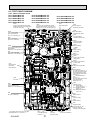
9-3. TEST POINT DIAGRAM
9-3-1. Indoor controller board
PLFY-P15VCM-E2.TH
PLFY-P20VCM-E2.TH
PLFY-P25VCM-E2.TH
PLFY-P32VCM-E2.TH
PLFY-P40VCM-E2.TH
CN2M
Connect to the terminal block (TB5)
(M-NET transmission connecting wire)
24-30V DC (non-polar)
PLFY-P15VCM-E2R1.TH
PLFY-P20VCM-E2R1.TH
PLFY-P25VCM-E2R1.TH
PLFY-P32VCM-E2R1.TH
PLFY-P40VCM-E2R1.TH
PLFY-P20VCM-E2R2.TH
PLFY-P25VCM-E2R2.TH
PLFY-P32VCM-E2R2.TH
PLFY-P40VCM-E2R2.TH
CN3A
Connect to the terminal block (TB15)
(MA-Remote controller connecting wire)
Between 1 to 3 8.7-13V DC (Pin1 (+))
CN31
Drain sensor (DS)
LED2
Power supply for
MA-Remote controller
CN29
Pipe temperature
detection/Gas (TH23)
CN2D
Connect to the indoor
power board (CN2S)
12.5-13.7V DC (Pin1 (+))
CN21
Pipe temperature
detection/Liquid (TH22)
LED1
Main power supply
(Indoor unit : 220-240V)
CN20
Room temperature
detection (TH21)
SW11
Address setting
1s DIGIT
CNDK
Connect to the indoor power
board (CNSK)
Between 1 to 3 220-240V AC
SW12
Address setting
10ths DIGIT
CNP
Drain pump output (DP)
Between 1 to 3 220-240V AC
SW14
Branch No.
CN60
Linear expansion valve
output (LEV)
CN90
Connect to the wireless
junction cable
CNC
Dew prevention
heater (H2)
(220~240V AC)
CN6V
Vane motor output (MV)
CN52
Remote indicator
1-2: Status lamp 12VDC (1 : +)
Fan motor output (SW1-5 OFF)
Thermostat ON (SW1-5 ON)
1-3: Cooling/Dry status lamp
12VDC (1 : +)
1-4: Heating status lamp
12VDC (1 : +)
When only demand input is used
1-5: Demand input
ON/OFF input (1 : +)
FUSE
6.3A 250V
CND
Power supply for
indoor controller board
Between 1 to 3 220-240V AC
CN51
Centrally control
1-2: Control signal
12VDC pulse input (1: +)
3-4: Operation indicator
12VDC (3: +)
3-5: Malfunction indicator
12VDC (3: +)
FAN
Fan motor output (MF)
SW4
Model selection
SW3
Function setting
SW1
Model selection
SW2
Capacity setting
Jumper wire J41, J42
Pair No. setting for
wireless remote controller
The voltage range of DC12V in this page
is between DC11.5 V to DC13.7 V.
OCH463C
CN27
Connector (Damper)
12VDC (1 : +)
27
CN32
Connector
(Remote switch)
CN25
Connecter (Humidifier)
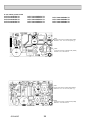
9-3-2. Indoor power board
PLFY-P15VCM-E2.TH
PLFY-P20VCM-E2.TH
PLFY-P25VCM-E2.TH
PLFY-P32VCM-E2.TH
PLFY-P40VCM-E2.TH
PLFY-P15VCM-E2R1.TH
PLFY-P20VCM-E2R1.TH
PLFY-P25VCM-E2R1.TH
PLFY-P32VCM-E2R1.TH
PLFY-P40VCM-E2R1.TH
PLFY-P20VCM-E2R2.TH
PLFY-P25VCM-E2R2.TH
PLFY-P32VCM-E2R2.TH
PLFY-P40VCM-E2R2.TH
CN2S
Connect to the indoor controller board (CN2D)
Between 1 to 3 12.5-13.7V DC (Pin1 (+))
CNSK
Connect to the indoor controller board (CNDK)
Between 1 to 3 220-240V AC
CN2S
Connect to the indoor controller board (CN2D)
Between 1 to 3 12.5-13.7V DC (Pin1 (+))
CNSK
Connect to the indoor controller board (CNDK)
Between 1 to 3 220-240V AC
OCH463C
28
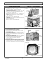
10
DISASSEMBLY PROCEDURE
PLFY-P15VCM-E2.TH
PLFY-P20VCM-E2.TH
PLFY-P25VCM-E2.TH
PLFY-P32VCM-E2.TH
PLFY-P40VCM-E2.TH
PLFY-P15VCM-E2R1.TH
PLFY-P20VCM-E2R1.TH
PLFY-P25VCM-E2R1.TH
PLFY-P32VCM-E2R1.TH
PLFY-P40VCM-E2R1.TH
PLFY-P20VCM-E2R2.TH
PLFY-P25VCM-E2R2.TH
PLFY-P32VCM-E2R2.TH
PLFY-P40VCM-E2R2.TH
Be careful when removing heavy parts.
OPERATING PROCEDURE
PHOTOS & ILLUSTRATIONS
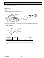
1. Removing the air intake grille
(1) Slide the knob of air intake grille to the direction of the
arrow 1 to open the air intake grille.
(2) Remove the string hook from the panel to prevent the grille
from dropping.
(3) Slide the hinge of the intake grille to the direction of the
arrow 2 and remove the air intake grille.
2. Removing the fan guard
(1) Open the air intake grille.
(2) Remove the 3 screws of fan guard.
Figure 1
Air intake grille
Air intake grille knob
Grille
Photo 1
Fan guard
Screws
Air intake grille
3. Removing the panel
(1) Remove the air intake grille. (Refer to procedure 1)
Corner panel (See Figure 2)
(1) Remove the screw of the corner.
(2) Slide the corner panel to the direction of the arrow 3, and
remove the corner panel.
Panel (See Photo 2)
(1) Disconnect the connector that connects with the unit.
(2) Remove the 2 screws from the panel and loose other 2
screws fixed to the oval hole, have different diameter.
(3) Rotate the panel a little to remove the screws. (Slide the
panel so that the screw comes to a larger diameter of the
oval hole, which has 2 different diameters.)
Figure 2
Corner
Screw panel
Corner
panel
Photo 2
Screws
Connector
Screws
Panel
Photo 3
4. Removing the electrical parts
(1) Remove the 2 screws and the control box cover.
<Electrical parts in the control box>
• Indoor controller board (I.B)
• Indoor power board (P.B)
• Fan motor capacitor (C1)
• Fuse (FUSE)
• Varistor (ZNR)
• Terminal block (TB)
Fan motor
capacitor
(C1)
Indoor
controller
board (I.B)
Indoor controller
box
OCH463C
29
Panel
Indoor
power
board
(P.B)
Varistor
(ZNR)
Terminal
block
(TB5)
Fuse
(FUSE)
Terminal
block
(TB15)
Terminal
block (TB2)
OPERATING PROCEDURE
PHOTOS & ILLUSTRATIONS
5. Removing the room temperature detection (TH21)
(1) Remove the panel. (Refer to procedure 3)
(2) Pull out the room temperature detection from the drain pan.
(3) Remove the 2 screws fixed to the control box cover, and
remove the control box cover.
(4) Remove the connector (CN20) from the indoor controller
board, and disconnect the room temperature detection.
Photo 4
Connectors
Control box
Drain plug
Screw
Screw
Room
temperature
detection
(TH21)
6. Removing the drain pan
(1) Remove the panel. (Refer to procedure 3)
(2) Remove the room temperature detection and the 2 lead
wires held with fastener; wireless controller board relay
connector (9P red) and panel relay connector (10P white).
(3) Remove the 4 screws fixed to the drain pan, and remove
the drain pan.
(4) Remove the fan guard. (Refer to procedure 2)
7. Removing the pipe temperature detection/liquid (TH22)
and pipe temperature detection/gas (TH23)
(1) Remove the panel. (Refer to procedure 3)
(2) Remove the drain pan. (Refer to procedure 6)
(3) Disconnect the pipe temperature detection/liquid or the pipe
temperature detection/gas from the holder.
(4) Remove the 3 screws fixed to the piping cover, and remove
the piping cover. (See Photo 9)
(5) Remove the 2 screws fixed to the control box cover, and
remove the control box cover.
Drain pan
Screw
Screw
Fan guard
Photo 5
Control box
LEV
Pipe temperature detection/liquid (TH22)
(6) Remove the connector (CN21) from the indoor controller
board, and disconnect the pipe temperature detection/liquid.
Pipe temperature detection/gas (TH23)
(6) Remove the connector (CN29) from the indoor controller
board, and disconnect the pipe temperature detection/gas
with its holder.
Thermistor
(Pipe temperature
detection/ Liquid)
(TH22)
8. Removing the fan motor (MF)
Photo 6
(1) Remove the panel. (Refer to procedure 3)
(2) Remove the drain pan. (Refer to procedure 6)
Nut
(3) Remove the nut and the washer from the turbo fan, and
Flat
plate
remove the turbo fan.
(4) Remove the 2 screws fixed to the control box cover, and
remove the control box cover.
(5) Disconnect the connector of the FAN from the indoor conFan
troller board.
(6) Remove the 3 screws fixed to the piping cover, and remove motor
(MF)
the piping cover. (See Photo 9)
(7) Remove the 6 screws fixed to the flat plate, and remove
the flat plate.
(8) Disconnect the lead wires to the direction of the fan motor,
and remove the 3 nuts of the fan motor.
Screws
OCH463C
30
Thermistor
(Pipe temperature
detection/ Gas)
(TH23)
Screws
Lead
wires
Nuts
Screws
OPERATING PROCEDURE
PHOTOS & ILLUSTRATIONS
9. Removing the drain pump (DP) and drain sensor (DS)
(1) Remove the panel. (Refer to procedure 3 )
(2) Remove the drain pan. (Refer to procedure 6)
(3) Remove the 2 screws fixed to the control box cover, and
remove the control box cover.
(4) Remove the connectors of the (CNP) and the (CN31)
from the indoor controller board.
(5) Remove the 1 screw fixed to the cover, and remove the
cover.
(6) Disconnect the lead wires to the direction of the drain
pump. (See Photo 7)
(7) Remove the 3 screws of the drain pump.
(8) Cut the drain hose band, pull out the drain hose from the
drain pump.
(9) Pull out the drain pump.
(10) Remove the drain sensor and the holder.
Photo 7
Screw
Cover
Control
box
Lead wires
Photo 8
Drain sensor (DS)
Drain pump (DP)
Drain
hose
Screws
Screw
10. Removing the heat exchanger
(1) Remove the panel. (Refer to procedure 3 )
(2) Remove the drain pan. (Refer to procedure 6)
(3) Remove the nut and the washer from the turbo fan, and
remove the turbo fan.
(4) Remove the 2 screws fixed to the control box cover, and
remove the control box cover.
(5) Disconnect the connector of the FAN from the indoor controller board.
(6) Remove the 3 screws fixed to the piping cover, and remove
the piping cover. (See Photo 9)
(7) Remove the pipe temperature thermistor/liquid and
condenser/evaporator temperature thermistor.
(Refer to procedure 7)
(8) Disconnect the lead wires to the direction of the fan motor.
(9) Remove the 1 coil support screw, the 2 inside coil screws
(See Photo 10), and the 4 outside coil screws (See Photo 9)
from the heat exchanger, and remove the heat exchanger.
Fixing band
Control box
Photo 9
Screws of
piping cover
Control box
Coil
screws
Piping cover
Lead wires
Photo 10
Coil screws
Coil
support
OCH463C
31
Coil
support Screw
Heat exchanger
TM
HEAD OFFICE : TOKYO BLDG., 2-7-3, MARUNOUCHI, CHIYODA-KU TOKYO 100-8310, JAPAN
cCopyright 2009 MITSUBISHI ELECTRIC CORPORATION
Distributed in Dec. 2012 No. OCH463 REVISED EDITION-C
Distributed in Aug. 2012 No. OCH463 REVISED EDITION-B
Distributed in Dec. 2011 No. OCH463 REVISED EDITION-A
Distributed in May 2009 No. OCH463 PDF 6
Made in Japan
New publication, effective Dec. 2012
Specifications are subject to change without notice.