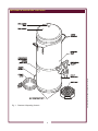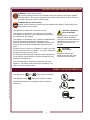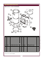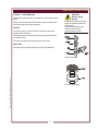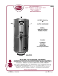
1
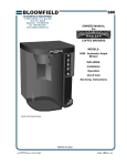
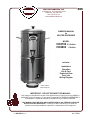
595
WELLS BLOOMFIELD, LLC
10 Sunnen Dr., St. Louis, MO 63143
telephone: 314-678-6314
fax: 314-781-2714
www.wellsbloomfield.com
OWNERS MANUAL
for
HEATED DISPENSER
MODEL
HD8799 2½-Gallon
HD8802 5-Gallon
Includes:
Installation
Operation
Use & Care
Exploded View
Parts List
Wiring Diagram
Model HD8799
Heated Dispenser
IMPORTANT: DO NOT DISCARD THIS MANUAL
This manual is considered to be part of the appliance and is to be given to the OWNER or
MANAGER of the restaurant, or to the person responsible for TRAINING OPERATORS of
this appliance. Additional manuals are available from your WELLS DEALER.
THIS MANUAL MUST BE READ AND UNDERSTOOD BY ALL PERSONS USING OR
INSTALLING THIS APPLIANCE. Contact your WELLS DEALER if you have any
questions concerning installation, operation or maintenance of this equipment.
p/n 2M-75982 Rev. G
M595
120322
LIMITED WARRANTY STATEMENT
Unless otherwise specified, all commercial cooking
equipment manufactured by WELLS BLOOMFIELD, LLC is
warranted against defects in materials and workmanship for
a period of one year from the date of original installation or
18 months from the date of shipment from our factory,
whichever comes first, and is for the benefit of the original
purchaser only.
THIS WARRANTY IS THE COMPLETE AND ONLY
WARRANTY, EXPRESSED OR IMPLIED IN LAW OR IN
FACT, INCLUDING BUT NOT LIMITED TO, WARRANTIES
OF MERCHANTABILITY OR FITNESS FOR ANY
PARTICULAR PURPOSE, AND/OR FOR DIRECT,
INDIRECT OR CONSEQUENTIAL DAMAGES IN
CONNECTION WITH WELLS BLOOMFIELD PRODUCTS.
This warranty is void if it is determined that, upon inspection
by an authorized service agency, the equipment has been
modified, misused, misapplied, improperly installed, or
damaged in transit or by fire, flood or act of God. It also
does not apply if the serial nameplate has been removed, or
if service is performed by unauthorized personnel. The
prices charged by Wells Bloomfield for its products are
based upon the limitations in this warranty. Seller’s
obligation under this warranty is limited to the repair of
defects without charge by a Wells Bloomfield factory
authorized service agency or one of its sub-service
agencies. This service will be provided on customer’s
premises for non-portable models. Portable models (a
device with a cord and plug) must be taken or shipped to
the closest authorized service agency, transportation
charges prepaid, for service. In addition to restrictions
contained in this warranty, specific limitations are shown in
the Service Policy and Procedure Guide. Wells Bloomfield
authorized service agencies are located in principal cities.
This warranty is valid in the United States and Canada and
void elsewhere. Please consult your classified telephone
directory, your foodservice equipment dealer or contact:
Wells Bloomfield, LLC
10 Sunnen Dr., St. Louis MO 63143 USA
phone (314) 678-6314 or fax (314) 781-2714
for information and other details concerning warranty.
SERVICE POLICY AND PROCEDURE GUIDE and ADDITIONAL WARRANTY EXCLUSIONS
1.
2.
3.
4.
6.
cleaning schedules, are customer responsibility. Those
miscellaneous adjustments noted are customer
responsibility. Proper attention to preventative
maintenance and scheduled maintenance procedures
will prolong the life of the appliance.
7. Travel mileage is limited to sixty (60) miles from an
Authorized Service Agency or one of its sub-service
agencies.
8. All labor shall be performed during regular working
hours. Overtime premium will be charged to the buyer.
9. All genuine Wells replacement parts are warranted for
ninety (90) days from date of purchase on nonwarranty equipment. This parts warranty is limited only
to replacement of the defective part(s). Any use of
non-genuine Wells parts completely voids any
warranty.
10. Installation, labor, and job check-outs are not
considered warranty and are thus not covered by this
warranty.
11. Charges incurred by delays, waiting time or operating
restrictions that hinder the service technician’s ability to
perform service are not covered by warranty. This
includes institutional and correctional facilities.
SHIPPING DAMAGE CLAIM PROCEDURE
NOTE: For your protection, please note that equipment in
this shipment was carefully inspected and packaged by
skilled personnel before leaving the factory. Upon
acceptance of this shipment, the transportation company
assumes full responsibility for its safe delivery.
IF SHIPMENT ARRIVES DAMAGED:
1. VISIBLE LOSS OR DAMAGE: Be certain that any
visible loss or damage is noted on the freight bill or
express receipt, and that the note of loss or damage is
signed by the delivery person.
2. FILE CLAIM FOR DAMAGE IMMEDIATELY:
Regardless of the extent of the damage.
3.
CONCEALED LOSS OR DAMAGE: if damage is
unnoticed until the merchandise is unpacked, notify the
transportation company or carrier immediately, and file
“CONCEALED DAMAGE” claim with them. This
should be done within fifteen (15) days from the date
the delivery was made to you. Be sure to retain the
container for inspection.
Wells Bloomfield cannot assume liability for damage or loss
incurred in transit. We will, however, at your request, supply
you with the necessary documents to support your claim.
xi
M595 p/n 2M-75982 Owners Manual Heated Dispenser
5.
Resetting of safety thermostats, circuit breakers, over
load protectors, and/or fuse replacements are not
covered by this warranty unless warranted conditions
are the cause.
All problems due to operation at voltages or phase
other than specified on equipment nameplates are
not covered by this warranty.
Conversion to correct voltage and/or phase must be
the customer’s responsibility.
All problems due to electrical connections not made
in accordance with electrical code requirements
and wiring diagrams supplied with the equipment are
not covered by this warranty.
Replacement of items subject to normal wear, to
include such items as knobs, light bulbs; and, normal
maintenance functions including adjustments of
thermostats, adjustment of micro switches and
replacement of fuses and indicating lights are not
covered by warranty.
Damage to electrical cords and/or plug due to exposure
to excessive heat are not covered by this warranty.
Full use, care, and maintenance instructions supplied
with each machine. Noted maintenance and
preventative maintenance items, such as servicing and
TABLE OF CONTENTS
WARRANTY
SPECIFICATIONS
FEATURES & OPERATING CONTROLS
PRECAUTIONS & GENERAL INFORMATION
AGENCY LISTING INFORMATION
INSTALLATION
OPERATION
CLEANING INSTRUCTIONS
TROUBLESHOOTING SUGGESTIONS
EXPLODED VIEW & PARTS LIST
WIRING DIAGRAM
SERVICING INSTRUCTIONS
PARTS & SERVICE
xi
1
2
3
3
4
5
6
7
8
10
11
13
INTRODUCTION
Thank You for purchasing this Wells Bloomfield appliance.
Proper installation, professional operation and consistent maintenance of this appliance will ensure that
it gives you the very best performance and a long, economical service life.
This manual contains the information needed to properly install this appliance, and to use and care for
the appliance in a manner that will ensure its optimum performance.
M595 p/n 2M-75982 Owners Manual Heated Dispenser
SPECIFICATIONS
MODEL
VOLTS
50/60 Hz
WATTS
AMPS
1ø
POWER SUPPLY
CORD
HD8799
HD8802
120
200
1.7
6' NEMA 5-15P
HD8799 2½-Gallon Dispenser
HEIGHT
OVERALL
WIDTH
OVERALL
DEPTH
CAPACITY
FIXED
TEMPERATURE
20 - 11/16"
(510 mm)
12 - 7/8"
(328 mm)
14 - 1/4"
(361 mm)
2 - 1/2 gallon
(10 liter)
140ºF
(60ºC)
HD8802 5-Gallon Dispenser
HEIGHT
OVERALL
WIDTH
OVERALL
DEPTH
CAPACITY
ADJUSTABLE TO
TEMPERATURE
24-1/4"
(621mm)
14-1/4"
( 361mm)
15"
( 381mm)
5 gallon
(20 liter)
170ºF
(77ºC)
1
FEATURES & OPERATING CONTROLS
M595 p/n 2M-75982 Owners Manual Heated Dispenser
Fig. 1
Features & Operating Controls
2
PRECAUTIONS AND GENERAL INFORMATION
WARNING: Electric Shock Hazard
All servicing requiring access to non-insulated components must be performed by qualified
service personnel. Do not open any access panels which require the use of tools. Failure to
heed this warning can result in electrical shock.
WARNING Electric Shock Hazard
Warmer must be properly grounded to prevent possible shock hazard. Electrical shock will
cause death or serious Injury.
This appliance is intended for commercial use only.
This appliance is intended for use to warm syrup for human
consumption. No other use is recommended or authorized by
the manufacturer or its agents.
This appliance is intended for use in commercial establishments,
where all operators are familiar with the appliance use,
limitations and associated hazards. Operating instructions and
warnings must be read and understood by all operators and
users.
Except as noted, this piece of equipment is made in the USA
and has American sizes on hardware. All metric conversions
are approximate and can vary in size.
The following trouble shooting, component views and parts lists
are included for general reference, and are intended for use by
qualified service personnel.
CAUTION: Equipment
Electrical Damage
DO NOT plug in or energize this
appliance until all Installation
Instructions are read and followed.
Damage to the warmer may occur
if these instructions are not
followed.
CAUTION:
Burn Hazard
Exposed surfaces of the
appliance may be HOT to the
touch and can cause burns.
This manual should be considered a permanent part of this
appliance. The manual must remain with the appliance if it is
sold or moved to another location.
M595 p/n 2M-75982 Owners Manual Heated Dispenser
AGENCY LISTING INFORMATION
This dispenser is
This dispenser meets
and
listed under UL file E9253
Standard 4 only when installed,
operated and maintained in accordance with the enclosed
instructions.
3
INSTALLATION
READ THIS CAREFULLY BEFORE STARTING THE INSTALLATION
CAUTION: Equipment
Electrical Damage
DO NOT plug in or energize this
appliance until all Installation
Instructions are read and
followed. Damage to the
Brewer will occur if these
instructions are not followed.
CAUTION: Unstable
Equipment Hazard
REFER TO EXPLODED VIEWS PAGE 9 FOR COMPONENT
NAMES/NUMBERS
Unpack the unit. Inspect all components for completeness and
condition. Ensure that all packing materials have been removed
from the unit.
LEVELING THE UNIT
Verify that a slip-resistant foot is installed at each corner of the
dispenser.
Set the warmer in its operating location. Be sure all four feet
touch the counter to prevent tipping.
ELECTRICIAN’S INSTALLATION INSTRUCTIONS
It is very important for safety
and for proper operation that the
warmer is level and stable when
standing in its final operating
position. Provided non-skid feet
must be installed at each corner
of the unit. Do not install this
appliance if the feet are missing
or damaged.
WARNING ELECTRIC
SHOCK HAZARD:
Models HD8799 and HD8802 dispensers are equipped with a
cord and plug. They requires a 115 - 125 volt circuit (50/60 Hz,
2 wire plus ground, with NEMA 5-15R receptacle).
IMPORTANT: The ground prong of the plug is part of a system
designed to protect you from electrical shock in the event of
internal damage. Never cut off the ground prong nor twist a
blade to fit an existing receptacle. Contact a licensed electrician
to install the proper circuit and receptacle.
GROUND
PIN
IMPORTANT:
Supply power must match
nameplate for voltage and
phase. Connecting to the
wrong voltage will damage the
warmer or result in decreased
performance. Such damage is
not covered by warranty.
NEMA 5-15P
PLUG
4
NEMA 5-15R
RECEPTACLE
M595 p/n 2M-75982 Owners Manual Heated Dispenser
Warmer must be properly
grounded to prevent possible
shock hazard. Electrical shock
will cause death or serious
injury.
REFER TO ELECTRICAL SPECIFICATIONS - Page 1
Check the nameplate to determine correct electrical service
required for the warmer.
OPERATION
PREPARATION
Prior to first use, thoroughly clean warmer (see page 6).
Be sure faucet handle is "up" and that drip tray is in place under
faucet.
CAUTION:
Burn Hazard
Exposed surfaces of the
appliance may be HOT to the
touch and can cause burns.
USE
Pour product into warming tank. Using pre-heated product will
reduce heat-up time.
Model HD8799 utilizes a fixed thermostat to hold
product at 140ºF (60ºC).
Model HD8802 thermostat may be adjusted to hold
product at 170ºF (77ºC) maximum.
Reinstall tank cover.
Plug dispenser into an appropriate electrical receptacle. Turn
power switch to ON.
When the READY light glows, product is ready to serve:
Place an appropriate container under the faucet.
Pull the faucet handle to dispense product.
Release the handle to stop the flow of product.
NOTE: Product may continue
to flow for several seconds after
the faucet is released. Do not
remove the container until all
flow has stopped.
IMPORTANT: Your local Health
Department can advise whether
or not a particular product may
be left in the dispenser overnight.
NIGHTLY CLOSE
Turn the power switch to OFF and unplug the dispenser.
If required, empty the dispenser and clean.
TEMPERATURE ADJUSTMENT (Model HD8802 only)
M595 p/n 2M-75982 Owners Manual Heated Dispenser
Remove button plug from rear of dispenser to access thermostat.
Turn shaft of thermostat to adjust setpoint temperature. Turn the
shaft clockwise to increase temperature. Moving the shaft 1/8
turn will change the temperature approximately 10ºF.
5
IMPORTANT:
Temperature adjustment to be
performed by authorized
personnel only.
CLEANING INSTRUCTIONS
CAUTION:
Electric Shock
Hazard
Do not submerge or immerse
dispenser in water.
CAUTION:
PROCEDURE: Clean Heated Dispenser
PRECAUTIONS: Disconnect dispenser from electric power.
Drain product and allow dispenser to cool.
FREQUENCY:
Daily or after draining product from
dispenser
TOOLS:
Mild Detergent, Clean Soft Cloth or Sponge
Long Handle Bristle Brush
Burn Hazard
This procedure requires the
use of very hot water. Wear
protective gloves while
cleaning the warmer. Very hot
water can cause burns.
IMPORTANT:
DO NOT use steel wool, sharp
objects, or caustic, abrasive or
chlorinated cleansers to clean
the dispenser.
1. Disconnect warmer from electric power.
Drain product and allow warmer to cool before cleaning.
2. Fill warmer with very hot water.
3. Place an appropriate container under the faucet. Use a long
handle bristle brush to stir the water while draining the hot
water from the warmer.
4. Wipe the warmer inside and out with a soft cloth or sponge
dampened with water and mild detergent.
5. Rinse the warmer inside and out with a soft cloth or sponge
dampened with clean water.
6. Wipe the tank cover with a soft cloth or sponge dampened
with water and mild detergent. Rinse with clean water.
7. If necessary, clean the faucet and drip tray (see page 8).
8. Allow all components to air dry, then reassemble.
Procedure is complete
M595 p/n 2M-75982 Owners Manual Heated Dispenser
6
TROUBLESHOOTING SUGGESTIONS
SYMPTOM
POSSIBLE CAUSE
SUGGESTED REMEDY
Not plugged in or circuit breaker
off or tripped
Restore electric power to warmer
Power switch not ON
Turn power switch to ON
Internal wiring damage
Inspect wiring for burnt wires and
proper connections . Repair as
needed
Power cord damaged
Replace power cord
Thermostat damaged
Replace thermostat
Power switch damaged
Replace power switch
"Ready" light does not glow
Light or wiring damaged
Replace light and/or repair wiring
(dispenser operational)
Thermostat damaged
Replace thermostat
"Ready" light always glows
Thermostat damaged
Replace thermostat
Faucet seat contaminated
Clean faucet
Faucet seat cup damaged
Replace seat cup
Appliance will not heat
M595 p/n 2M-75982 Owners Manual Heated Dispenser
Faucet leaks
7
EXPLODED VIEW & PARTS LIST
MODEL HD8799 2½-GALLON DISPENSER
1
PART NO
2U-87737
DESCRIPTION
QTY ITEM
FAUCET ASSEMBLY
1
PART NO
DESCRIPTION
6
2N-75853
HEATING ELEMENT 120V 200W
QTY
1
1.1*
WS-8600-15
FAUCET SPB PLASTIC (BLK)
7
2T-75863
THERMOSTAT 140ºF 120V
1
1.2*
2U-71460
SEAT CUP
8
2E-30169
SWITCH 250V DPST
1
ASSEMBLY, HANDLE & PLUNGER
9
Z1-70-07-0343 GUARD, SWITCH
1.4*
WS-8600-27P
NUT RETAINING WINGED
10
2E-70017
POWER CORD, 120V NEMA5-15P, 6'
1
1.5*
2P-87740
11
WS-68689
STRAIN RELIEF 120V STRAIGHT
1
1.6*
2U-87739
C-RING, STAINLESS STEEL
12
2J-72671
LIGHT, SIGNAL GREEN 120V
1
1.7*
2C-87741
WASHER CLEAR PLASTIC SOFT
13
2L-71747
ASSEMBLY, DRIP TRAY (pk 6)
1
1.8*
2C-87742
WASHER HARD PLASTIC (BLK)
14
2A-45728
FOOT RUBBER #8-32 THREAD
4
1.9*
2C-87743
15
2C-31053
NUT #8-32 KEP
4
2
DD-85862
ASSEMBLY, TANK BODY
1
16
2C-35736
NUT #8-32 KEP GREEN
1
3
WS-8600-6
ASSEMBLY, TANK COVER
1
17
SCREW PAN PHL #6 x 3/8 DRILL POINT
6
BUTTON PLUG 3/8”
1
1.3*
SHANK, FAUCET W/O SIGHT GLASS
HEX NUT, PLASTIC M17 X 1.5 (BLK)
4
2L-75876
PANEL, TANK BOTTOM
5
WS-8600-7
KNOB, TANK COVER
18
1
* included in 2U-87737 FAUCET ASSEMBLY
8
2P-70275
1
M595 p/n 2M-75982 Owners Manual Heated Dispenser
Model: HD8799 2 1/2 Gallon Dispenser
ITEM
EXPLODED VIEW & PARTS LIST
M595 p/n 2M-75982 Owners Manual Heated Dispenser
MODEL HD8802 5-GALLON DISPENSER
Model: HD8802 5 Gallon Dispenser
ITEM
1
PART #
2U-87737
1.1*
WS-8600-15
1.2*
2U-71460
1.3*
DESCRIPTION
QTY
FAUCET ASSEMBLY
ITEM
PART #
DESCRIPTION
QTY
6
2N-75853
HEATING ELEMENT 120V 200W
1
FAUCET SPB PLASTIC (BLK)
7
DD-304682
THERMOSTAT ADJUST 170ºF 120V
1
SWITCH 250V DPST
1
SEAT CUP
8
2E-30330
ASSEMBLY, HANDLE & PLUNGER
9
Z1-70-07-0343 GUARD, SWITCH
10
2E-70017
POWER CORD, 120V NEMA5-15P, 6'
1
11
WS-68689
STRAIN RELIEF 120V STRAIGHT
1
12
2J-72671
LIGHT, SIGNAL GREEN 120V
1
1
1.4*
WS-8600-27P
NUT RETAINING WINGED
1.5*
2P-87740
SHANK, FAUCET W/O SIGHT GLASS
1.6*
2U-87739
C-RING, STAINLESS STEEL
1.7*
2C-87741
WASHER CLEAR PLASTIC SOFT
13
2L-71747
ASSEMBLY, DRIP TRAY (pk 6)
1
1.8*
2C-87742
WASHER HARD PLASTIC (BLK)
14
2A-45728
FOOT RUBBER #8-32 THREAD
4
1.9*
2C-87743
15
2C-31053
NUT #8-32 KEP
4
16
2C-55736
NUT #8-32 KEP GREEN
1
6
2
1
HEX NUT, PLASTIC M17 X 1.5 (BLK)
ASSEMBLY, TANK BODY
1
3
DD-8601-5
ASSEMBLY, TANK COVER
1
17
2C-73457
SCREW PAN PHL #6 x 3/8 DRILL
POINT
4
DD-306099
PANEL, TANK BOTTOM
1
18
2P-70275
BUTTON PLUG 3/8”
2
5
WS-8600-7
KNOB, TANK COVER
1
19
DD-306100
BRACKET, THERMOSTAT MOUNTING
1
* included in 85865 FAUCET ASSEMBLY
9
WIRING DIAGRAM
M595 p/n 2M-75982 Owners Manual Heated Dispenser
10
SERVICING INSTRUCTIONS
ACCESS - BOTTOM PANEL
All internal components are accessible by removing the bottom
panel.
Remove four screws around the bottom of the warmer tank to
free bottom panel from tank assembly.
FAUCET
The faucet may be removed from the shank by turning the
winged collar clockwise.
CAUTION
Electric Shock
Hazard
Opening the bottom panel will
expose uninsulated electrical
components.
Disconnect dispenser from
electrical power before
removing bottom panel.
The faucet bonnet may be removed by turning the bonnet nut
counterclockwise.
The seat cup snaps onto the end of the faucet stem.
DRIP TRAY
The grate sets in the drip tray base, and may be lifted out.
M595 p/n 2M-75982 Owners Manual Heated Dispenser
Faucet Assembly
Drip Tray Assembly
11
NOTES
M595 p/n 2M-75982 Owners Manual Heated Dispenser
12
PARTS & SERVICE
DESCRIPTION
PART NO.
DRIP TRAY
2L-71747
IMPORTANT: Use only
factory authorized service
parts and replacement
filters.
For factory authorized
service, or to order factory
authorized replacement parts,
contact your Wells authorized
service agency, or call:
Wells Bloomfield, LLC
10 Sunnen Dr.,
St. Louis MO 63143 USA
Service Dept.
phone: (314) 678-6314
fax:
(314) 781-2714
M595 p/n 2M-75982 Owners Manual Heated Dispenser
Service Parts Department can
supply you with the name and
telephone number of the
WELLS AUTHORIZED
SERVICE AGENCY
nearest you.
CUSTOMER SERVICE DATA
please have this information available if calling for service
RESTAURANT _____________________________ LOCATION _____________
INSTALLATION DATE ________________________ TECHNICIAN ___________
SERVICE COMPANY ________________________________________________
ADDRESS ___________________________ STATE ______ ZIP__________
TELEPHONE NUMBER (_____)_____-_________
EQUIPMENT MODEL NO. _______________
EQUIPMENT SERIAL NO. _______________
VOLTAGE: (check one)
120
13
WELLS BLOOMFIELD, LLC
10 Sunnen Dr., St. Louis, MO 63143
telephone: 314-678-6314
fax: 314-781-2714
www.wellsbloomfield.com