1
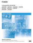
Getting Started Guide
Read this manual first and retain for future reference.
Contents
Color imageRUNNER
LBP5975/5970
Getting Started Guide
Preface .............................................................. 2
System Configuration Requirements for
Using User Manual CD-ROM........................... 4
Installation Site ................................................ 5
Important Safety Instructions ......................... 8
Introducing Your Print System...................... 12
Step1 Taking the Printer Out of the Package and
Installing the Printer ...................................... 13
Confirming the Contents of the Box ..........................13
Carrying the Printer to the Installation Site................13
Removing the Packing Materials ...............................15
Step2
Step3
Step4
Step5
Step6
Connecting the Power Cord.......................... 21
Installing the Drum Cartridges ..................... 22
Installing the Toner Cartridges ..................... 32
Loading Paper in the Paper Cassette........... 35
Connecting to a Computer............................ 40
Using a LAN Cable ....................................................40
Using a USB Cable ...................................................41
Step7 Turning the Printer ON and Checking the
Printer Operation ........................................... 43
Turning the Printer ON...............................................43
Checking the Operations with Configuration Page Print ..... 44
When the Printer Does Not Operate Properly ...........45
Changing the Language Used in the Display ............45
Turning the Printer OFF.............................................46
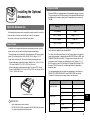
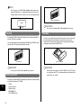
Step8 Installing the Optional Accessories ............. 49
Optional Accessories.................................................49
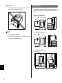
Installing a Paper Feeder ......................................... 51
Installing RAM/ROM ................................................. 61
Installing a Hard Disk ............................................... 65
Installing NB-W2....................................................... 68
1
Preface
IMPORTANT
To view the manual in PDF format, Adobe Reader/Acrobat Reader/Acrobat
is required. If Adobe Reader/Acrobat Reader/Acrobat is not installed on
Manuals
your system, please download it from the Adobe Systems Incorporated
The manuals for this machine are divided as follows. Please refer to them for
detailed information.
■ Getting Started Guide (this manual)
Describes the procedures for setting the printer hardware, such as the
procedures for installing the printer, connecting the printer to a computer, and
installing the optional accessories.
■ User's Guide
website (http://www.adobe.com).
Conventions
The following symbols are used in this manual to explain procedures,
restrictions, handling precautions, and instructions that should be observed
for safety.
WARNING
CD-ROM
Describes the things you need to know when using this printer, such as the
parts and their functions of the printer, basic usages, procedures for replacing
Indicates a warning concerning operations that may lead to death or
injury to persons if not performed correctly. In order to use the
printer safely, always pay attention to these warnings.
the consumables, troubleshooting, settings that you can specify using the
control panel, and specifications.
■ Driver Guide
CD-ROM
Describes the settings and operations that you perform on the computer, such
as the printer driver installation on various operating systems, printing, and
utility software.
■ Remote UI Guide
CD-ROM
CAUTION
Indicates a caution concerning operations that may lead to injury to
persons, or damage to property if not performed correctly. In order to
use the printer safely, always pay attention to these cautions.
IMPORTANT
Indicates operational requirements and restrictions. Be sure to read
these items carefully in order to operate the printer correctly, and to
avoid damage to the printer.
Describes the procedures for setting the printer using the web browser.
NOTE
■ Network Guide
CD-ROM
Describes the procedures for setting the printer to be used on a network, such
as the procedures for configuring various types of networks and
Indicates a clarification of an operation, or contains additional
explanations for a procedure. Reading these notes is highly
recommended.
troubleshooting for when using the printer on a network.
Copyright 2008 by Canon Inc. All rights reserved.
Guides with this symbol are printed manuals.
CD-ROM
Guides with this symbol are PDF manuals included on the
accompanying CD-ROM. The PDF manuals are available from
"CD-ROM Menu". (See "Using the User Manual CD-ROM Menu,"
on p. 4)
2
No part of this publication may be reproduced or transmitted in any form or by
any means, electronic or mechanical, including photocopying and recording,
or by any information storage or retrieval system without the prior written
permission of Canon Inc.
Notice
Canon makes no guarantees of any kind with regard to this manual. Canon
shall not be held liable for errors contained herein or for consequential or
incidental damages incurred as a result of acting on information contained in
the manual.
For CA, USA only
Abbreviations Used in This Manual
Included battery contains Perchlorate Material - special handling may apply.
In this manual, product names and model names are abbreviated as follows:
Microsoft Windows 2000:
Microsoft Windows XP:
Microsoft Windows Server 2003:
Microsoft Windows Vista operating system:
Windows 2000
Windows XP
Windows Server 2003
Windows Vista
Microsoft Windows operating system:
Windows
Wireless Network Interface Board NB-W2:
NB-W2
Color imageRUNNER LBP5975:
LBP5975
Color imageRUNNER LBP5970:
LBP5970
Trademarks
Canon, the Canon logo, imageRUNNER, and LBP are trademarks of Canon
Inc.
Adobe, Adobe Acrobat, and Adobe Reader are trademarks of Adobe
Systems Incorporated.
Apple, AppleTalk, Mac OS, and Macintosh are trademarks of Apple Inc.,
registered in the U.S. and other countries.
See http://www.dtsc.ca.gov/hazardouswaste/perchlorate/ for details.
Third Party Software
This product includes software and/or software modules that are licensed by
third parties (LICENSORS). Use and distribution of these software and/or
software modules (the "SOFTWARE") are subject to conditions (1) through
(9) below unless the other conditions accompany the software and/or
software modules. In such cases, these software and/or software modules
are subject to the other conditions.
(1) You agree that you will comply with any applicable export control laws,
restrictions or regulations of the countries involved in the event that the
SOFTWARE is shipped, transferred or exported into any country.
(2) LICENSORS retain in all respects the title, ownership and intellectual
property rights in and to the SOFTWARE. Except as expressly provided
herein, no license or right, expressed or implied, is hereby conveyed or
granted by Canon's licenser to you for any intellectual property of
LICENSORS.
BarDIMM is a registered trademark of Jetmobile SAS.
(3) You may use the SOFTWARE solely for use with the Canon product you
purchased (the "PRODUCT").
Microsoft, Windows, and Windows Vista are trademarks or registered
trademarks of Microsoft Corporation in the U.S. and/or other countries.
Novell, NetWare are trademarks of Novell, Inc.
(4) You may not assign, sublicense, market, distribute, or transfer the
SOFTWARE to any third party without prior written consent of Canon and
LICENSORS.
UNIX is a registered trademark of The Open Group in the United States and
other countries.
(5) Notwithstanding the foregoing, you may transfer the SOFTWARE only
when (a) you assign all of your rights to the PRODUCT and all rights and
obligations under the conditions to transferee and (b) such transferee
agrees to be bound by all these conditions.
Ethernet is a trademark of Xerox Corporation.
Other product and company names herein may be the trademarks of their
respective owners.
Disclaimers
The information in this manual is subject to change without notice.
CANON INC. MAKES NO WARRANTY OF ANY KIND WITH REGARD TO
THIS MATERIAL, EITHER EXPRESS OR IMPLIED, EXCEPT AS
PROVIDED HEREIN, INCLUDING WITHOUT LIMITATION, THEREOF,
WARRANTIES AS TO MARKETABILITY, MERCHANTABILITY, FITNESS
FOR A PARTICULAR PURPOSE OF USE OR AGAINST INFRINGEMENT
OF ANY PATENT. CANON INC. SHALL NOT BE LIABLE FOR ANY DIRECT,
INCIDENTAL, OR CONSEQUENTIAL DAMAGES OF ANY NATURE, OR
LOSSES OR EXPENSES RESULTING FROM THE USE OF THIS
MATERIAL.
(6) You may not decompile, reverse engineer, disassemble or otherwise
reduce the code of the SOFTWARE to human readable form.
(7) You may not modify, adapt, translate, rent, lease or loan the SOFTWARE
or create derivative works based on the SOFTWARE.
(8) You are not entitled to remove or make separate copies of the
SOFTWARE from the PRODUCT.
(9) The human-readable portion (the source code) of the SOFTWARE is not
licensed to you.
3
System Configuration
Requirements for Using User
Manual CD-ROM
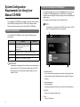
Using the User Manual CD-ROM Menu
This section describes how to use the CD-ROM Menu. When you insert the
User Manual CD-ROM provided into the CD-ROM drive, the Language
Selection screen is displayed. Clicking a language on this screen displays the
following menu.
(The sample screen shot shown here is for Windows users.)
The User Manual CD-ROM Menu is software that enables you to select and
view PDF Manuals included on the CD-ROM via your computer screen.
Follow the instructions below to use the User Manual CD-ROM Menu.
NOTE
For Macintosh users, double-click the [START] icon to start the CD-ROM
Menu. The Language Selection screen is displayed.
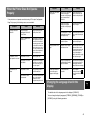
System Requirements
a
The User Manual CD-ROM Menu can be used in the following system
environments.
Windows
Macintosh
Operating System
Windows 2000 (Service Pack 3 or later)
Windows XP (Service Pack 1a or later)
Windows Server 2003
Windows Vista
Mac OS X
Memory
The memory required to run the above operating systems.
Computer
A computer that can run the above operating systems.
Display
A resolution of 1024 x 768 pixels or higher.
b
IMPORTANT
Depending on the configuration of your computer, some functions may not
c
operate correctly. If the PDF manual does not open from the CD-ROM
Menu, open the PDF file directly from the [english] folder on the User
Manual CD-ROM.
d
a BROWSE MANUAL
You can read any of the listed guides by clicking on the desired guide. After
clicking on the desired guide, Acrobat Reader starts, and the PDF manual is
displayed.
b Canon Font Manager
Install Font Manager.
Font Manager supports only English, French, German, Italian, and Spanish.
c RETURN
Return to the Language Selection screen.
d EXIT
Exit the CD-ROM menu.
4
Installation Site
● Install the printer in the following locations.
- A location where sufficient space can be secured
- A well-ventilated room
Installation Environment
In order to use this printer in a safe and comfortable manner, install the printer in
a place that fulfills the following conditions.
IMPORTANT
Before installing the printer, be sure to read "Important Safety Instructions"
(See p. 8).
- A flat, even surface
- A sturdy platform that can easily support the weight of the printer and optional
accessories
WARNING
Do not install the printer near alcohol, paint thinner, or other
flammable substances. If flammable substances come into contact
with electrical parts inside the printer, it may result in a fire or
electrical shock.
● Use power supplies rated for voltages in the following ranges.
120 to 127 V 60 Hz
● The maximum power consumption is 1,240 W or less.
Before connecting the printer to the power supply, make sure that the power
supply is safe and its voltage is stable.
● Use the printer in a location where the temperature and humidity are in the
following ranges.
CAUTION
• Do not install the printer in the following locations, as this may result
in a fire or electrical shock.
- A damp or dusty location
- A location exposed to smoke and steam such as cookeries and
humidifiers
Ambient temperature: 50 to 86°F (10 to 30°C)
- A location exposed to rain or snow
Ambient humidity: 10 to 80 % RH (no condensation)
- A location near water faucets or water
IMPORTANT
Water droplets (condensation) may form inside the printer under the
following circumstances. Leave the printer for two hours or more to adjust
to the surrounding temperature and humidity before using it. If water
- A location exposed to direct sunlight
- A location subject to high temperatures
- A location near open flames
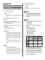
• The weight of the printers is as follows.
droplets form inside the printer, the paper transport path will not function
properly, and this may result in paper jams, damage to the printer, or
Default
printer error.
- When the room where the printer is installed is heated rapidly
- When the printer is moved from a cool or dry location to a hot or humid
location
NOTE
To customers using an ultrasonic humidifier
If you use an ultrasonic humidifier in conjunction with tap water or well
water, impurities in the water will be dispersed through the air. These can
be trapped inside the printer, causing degradations in printing quality.
When you are using these humidifiers, it is therefore recommended that
you use purified water or other water that is free of impurities.
With the toner
cartridges and
drum cartridges
installed
With the optional
paper feeders (3
units) installed
LBP5975
Approx. 115.7 lb Approx. 135.4 lb Approx. 208.1 lb
(52.5 kg)
(61.4 kg)
(94.4 kg)
LBP5970
Approx. 106.9 lb Approx. 126.5 lb Approx. 199.3 lb
(48.5 kg)
(57.4 kg)
(90.4 kg)
Be sure to install the printer on a sturdy platform that can easily
support the weight of the printer and optional accessories. Do not
install the printer in unstable locations, such as unsteady platforms
or inclined floors, in locations subject to excessive vibrations, or on
the upper row of a computer rack, as this may cause the printer to fall
or tip over, resulting in personal injury.
5
IMPORTANT
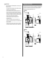
Dimensions of the Printer
Do not install the printer in the following locations, as this may result in
- A location near products that generate magnetic waves or
electromagnetic waves
LBP5975
Front Surface
1.78 (45)
(in. (mm))
10.16 (258)
6.30
(160)
Toner cover
Front cover
Paper cassette
- In rooms such as laboratories where chemical reactions occur
- A place where salt content, corrosive gases such as ammonia, or toxic
gases are contained
- A platform that may warp from the weight of the printer and optional
accessories, or the printer is liable to sink (such as a carpet or mat)
Top cover
14.96 (380) 11.81 (300)
- A poorly ventilated room (Ozone is generated by the printer in use,
however, the amount is too small to be harmful to the human body.
However, if you are going to use the printer for a long time in a poorly
ventilated room or to perform a large amount of printing, ventilate the
room to keep the working environment comfortable.)
3.07 (78)
- An environment where the temperature and/or humidity can change
dramatically, or where condensation occurs
The dimensions of each part of the printer are indicated in the following figures.
For details on the dimensions of the printer with the optional paper feeder
installed, see "Installing a Paper Feeder," on p. 51.
21.46 (545)
damage to the printer.
Tray extension
Auxiliary tray
Multi-purpose tray
25.06 (636.5)
9.06 (230)
25.63 (651)
0.73 (18.5)
LBP5970
Front Surface
(in. (mm))
6.30
(160)
Toner cover
Front cover
21.46 (545)
Paper cassette
Top cover
Tray extension
Auxiliary tray
Multi-purpose tray
25.06 (636.5)
6
9.06 (230)
25.63 (651)
14.96 (380) 11.81 (300)
10.16 (258)
3.07 (78)
1.78 (45)
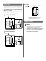
Select an installation location where you can secure the following amounts of
free space around the printer, and a surface that can support the weight of the
printer. The dimensions of the space required around the components and the
positions of the feet are as follows.
For details on the installation space of the printer with the optional paper feeder
installed, see "Installing a Paper Feeder," on p. 51.
Front Surface
1.77 (45) 16.46 (418)
Required Peripheral Space (LBP5975)
2.48
(63)
17.43
(442.7)
3.99
(101.3)
2.48
(63)
17.43
(442.7)
3.99
(101.3)
30.71 (780)
3.94
(100)
(in. (mm))
Front cover
Paper
cassette
(in. (mm))
The rubber feet are 6 mm high, and dimensions of the top surface are 0.59 in. (15 mm) x 0.91 in.
(23 mm) for the front feet, and 0.94 in. (24 mm) x 0.39 in. (10 mm) for the rear feet.
(in. (mm))
Top cover
3.94
(100)
29.33 (745)
29.13 (740)
3.94
(100)
Front Surface
1.56 (39.6) 16.37 (415.7) 3.53 (89.7)
Foot Positions
3.23 (82)
Installation Space
Precautions for Handling
CAUTION
If an error should occurred to the hard disk in the printer unit, the
5.32
(135)
received, recorded, and saved data may be deleted. It is
recommended not to record or save important data on the hard disk.
60.81 (1544.5)
Canon assumes no responsibility whatsoever for any damages or
losses arising from data loss by the customers.
Required Peripheral Space (LBP5970)
Top cover
Front cover
Paper
cassette
3.94
(100)
29.33 (745)
29.13 (740)
(in. (mm))
30.71 (780)
(in. (mm))
3.94
(100)
3.94
(100)
Front Surface
5.32
(135)
60.08 (1526)
7
Important Safety Instructions
CAUTION
• Do not install the printer in unstable locations, such as unsteady
Please read these "Important Safety Instructions" thoroughly before
operating the printer. As these instructions are intended to prevent injury to
the user or other persons or destruction of property, always pay attention to
these instructions. Also, since it may result in unexpected accidents or
injuries, do not perform any operation unless otherwise specified in the
manual. Improper operation or use of this machine could result in personal
injury and/or damage requiring extensive repair that may not be covered
under your Limited Warranty.
platforms or inclined floors, or in locations subject to excessive
vibrations, as this may cause the printer to fall or tip over, resulting in
personal injury.
• Never block the ventilation slots on the printer. The ventilation slots
are provided for proper ventilation of working parts inside the printer.
Never place the printer on a soft surface, such as a sofa or rug.
Blocking the ventilation slots can cause the printer to overheat,
resulting in a fire.
Installation
• Do not install the printer in the following locations, as this may result
in a fire or electrical shock.
WARNING
- A damp or dusty location
• Do not install the printer near alcohol, paint thinner, or other flammable
substances. If flammable substances come into contact with electrical
- A location exposed to smoke and steam such as cookeries and
humidifiers
parts inside the printer, it may result in a fire or electrical shock.
- A location exposed to rain or snow
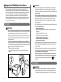
• Do not place the following items on the printer. If these items come into
contact with electrical parts inside the printer, this may result in a fire
- A location near water faucets or water
- A location exposed to direct sunlight
- A location subject to high temperatures
or electrical shock.
If these items are dropped or slipped inside the printer, immediately
- A location near open flames
turn OFF the printer and computer a and disconnect the USB cable b
• When installing the printer, gently lower the printer onto the floor or
if it is connected. Then, unplug the power plug from the AC power outlet
other machine to avoid catching your hands, as this may result in
c and contact your local authorized Canon dealer.
personal injury.
• When connecting the interface cable, connect it properly following
- Necklaces and other metal objects
- Cups, vases, flowerpots, and other containers filled with water or
liquids
the instructions in this manual. If not connected properly, this may
result in malfunction or electrical shock.
• When moving the printer, follow the instructions in this manual to
hold it correctly. Failure to do so may cause you to drop the printer,
b
resulting in personal injury. (See Moving the Printer:
CD-ROM
User's
Guide)
a
c
Power Supply
WARNING
• Do not damage or modify the power cord. Also, do not place heavy
a
8
objects on the power cord, or pull on or excessively bend it, as this
could cause electrical damage and result in a fire or electrical shock.
• Keep the power cord away from a heat source; failure to do this may
cause the power cord coating to melt, resulting in a fire or electrical
Handling
shock.
• Do not plug or unplug the power plug with wet hands, as this may
result in electrical shock.
• Do not plug the power cord to a multiplug power strip, as this may
cause a fire or electrical shock.
• Do not bundle up or tie the power cord in a knot, as this may result in a
fire or electrical shock.
• Insert the power plug completely into the AC power outlet, as failure to
do so may result in a fire or electrical shock.
• Do not use power cords other than the power cord provided, as this
may result in a fire or electrical shock.
• As a general rule, do not use extension cords or plug extension cords
to a multiple power strip. If extension cords must be used or plugged to
a multiple power strip, however, use them observing the following
points on user's own authority. If you use extension cords improperly,
this may result in a fire or electrical shock.
- Do not connect one extension cord to another.
- Make sure that the voltage of the power plug is the one indicated in
the rating label (attached on the back of the printer) when you use the
printer.
- Use an extension cord that allows the current value greater than the
necessary one indicated in the rating label (attached on the back of
the printer).
WARNING
• Do not attempt to disassemble or modify the printer. There are hightemperature and high-voltage components inside the printer which may
result in a fire or electrical shock.
• Electrical equipment can be hazardous if not used properly. To avoid
injury, do not allow children access to the interior of any electrical
product and do not let them touch any electrical contacts or gears that
are exposed.
• If the printer makes strange noises, or emits smoke, heat or unusual
smells, immediately turn OFF the printer and computer, and disconnect
the USB cable if it is connected. Then, unplug the power plug from the
AC power outlet and contact your local authorized Canon dealer.
Otherwise, this may result in a fire or electrical shock.
• Do not use highly flammable sprays near the printer. If gas from these
sprays comes into contact with the electrical components inside the
printer, it may result in a fire or electrical shock.
• Always turn OFF the printer and computer, and disconnect the
interface cables when moving the printer. Otherwise, the power cord or
interface cables may be damaged, resulting in a fire or electrical shock.
• Do not drop paper clips, staples, or other metal objects inside the
printer. Also, do not spill water, liquids, or flammable substances
(alcohol, benzene, paint thinner, etc.) inside the printer. If these items
- When you use an extension cord, untie the cord binding, and insert
the power plug completely into the extension cord outlet to ensure a
firm connection between the power cord and the extension cord.
come into contact with a high-voltage area inside the printer, this may
- Periodically check that the extension cord is not overheated.
disconnect the USB cable if it is connected. Then, unplug the power
result in a fire or electrical shock. If these items are dropped or slipped
inside the printer, immediately turn OFF the printer and computer, and
plug from the AC power outlet and contact your local authorized Canon
CAUTION
• Do not use power supplies with voltages other than those specified
herein, as this may result in a fire or electrical shock.
• Always grasp the plug when unplugging the power cord. Pulling on
dealer.
• When plugging or unplugging the USB cable when the power plug is
plugged in an AC power outlet, do not touch the metal part of the
connector, as this may result in electrical shock.
the power cord may expose or snap the core wire, or otherwise
damage the power cord. If the power cord is damaged, this could
cause current to leak, resulting in a fire or electrical shock.
• Leave sufficient space around the power plug so that it can be
CAUTION
• Do not place heavy objects on the printer, as they may tip over or fall
resulting in personal injury.
unplugged easily. If objects are placed around the power plug, you
will be unable to unplug it in an emergency.
9
• Be careful when handling the main board, expansion board, RAM,
and ROM. Touching the edges or a sharp portion of the main board,
Maintenance and Inspections
expansion board, RAM, and ROM may result in personal injury.
• Turn OFF the power switch for safety when the printer will not be
used for a long period of time such as overnight. Also, turn OFF the
WARNING
• When cleaning the printer, turn OFF the printer and computer, remove
power switch and unplug the power plug for safety when the printer
the USB cable, and then unplug the power plug. Failure to observe
will not be used for an extended period of time such as during
these steps may result in a fire or electrical shock.
consecutive holidays.
• Keep your hands or clothing away from the roller in the output area.
• Unplug the power plug from the AC power outlet regularly, and clean
the area around the base of the power plug's metal pins and the AC
Even if the printer is not printing, sudden rotation of the roller may
power outlet with a dry cloth to ensure that all dust and grime is
catch your hands or clothing, resulting in personal injury.
removed. If the power plug is plugged for a long period of time in a
• The laser beam can be harmful to human bodies. Since radiation
emitted inside the printer is completely confined within protective
housings and external covers, the laser beam cannot escape from
the printer during any phase of user operation. Read the following
damp, dusty, or smoky location, dust can build up around the power
plug and become damp. This may cause a short circuit and result in a
fire.
• Clean the printer using a slightly dampened cloth with water or a mild
remarks and instructions for safety.
detergent diluted with water. Do not use alcohol, benzene, paint
- Never open covers other than those instructed in this manual.
thinner, or other flammable substances. If flammable substances come
- Do not remove the caution label attached to the cover of the laser
scanner unit.
into contact with electrical parts inside the printer, it may result in a fire
or electrical shock.
• There are some areas inside the printer which are subject to highvoltages. When removing jammed paper or when inspecting the inside
of the printer, do not allow necklaces, bracelets, or other metal objects
to touch the inside of the printer, as this may result in burns or
electrical shock.
• Do not throw a used drum cartridge, toner cartridge, or waste toner
container into open flames, as this may cause the toner remaining
inside the cartridge to ignite, resulting in burns or a fire.
CAUTION
- If the laser beam escapes from the printer, exposure may cause
serious damage to your eyes.
• Never attempt to service this printer yourself, except as explained in
this manual. There are no user serviceable parts inside the printer.
Adjust only those controls that are covered in the operating
instructions. Improper adjustment could result in personal injury
and/or damage requiring extensive repair that may not be covered
under your Limited Warranty.
10
• The fixing unit and its surroundings (including the output area and
the staple cartridge for LBP5975) inside the printer are hot during
Consumables
use. When removing jammed paper or when inspecting the inside of
the printer, do not touch the fixing unit and its surroundings, as
WARNING
doing so may result in burns.
• Do not throw a used toner cartridge into open flames, as this may
cause toner remaining inside the cartridge to ignite and result in burns
or a fire.
• Do not store a toner cartridge or copy paper in places exposed to open
flames, as this may cause the toner or paper to ignite and result in
burns or a fire.
• Place the toner cartridge or drum cartridge into a plastic bag to prevent
its toner from scattering, and then dispose of the toner cartridge or
drum cartridge according to local regulations.
CAUTION
• When removing jammed paper or replacing a drum cartridge, toner
• Keep toner cartridges and other consumables out of the reach of
cartridge, or waste toner container, take care not to allow the toner to
small children. If these items are ingested, consult a physician
come into contact with your hands or clothing, as this will dirty your
hands or clothing. If they become dirty, wash them immediately with
immediately.
• Do not attempt to disassemble the toner cartridge, drum cartridge, or
cold water. Washing with warm water will set the toner and make it
waste toner container. The toner may scatter and get into your eyes
impossible to remove the toner stains.
or mouth. If the toner gets into your eyes or mouth, wash them
• When removing paper jammed inside the printer, remove the jammed
immediately with cold water and immediately consult a physician.
paper gently to prevent the toner on the paper from scattering and
• If toner leaks from the toner cartridge, drum cartridge, or waste toner
getting into your eyes or mouth. If the toner gets into your eyes or
container, be careful not to inhale the toner or allow it to come into
mouth, wash them immediately with cold water and immediately
contact with your skin directly. If the toner comes into contact with
consult a physician.
your skin, wash it out with soap. If you have an irritation on your skin,
• When loading paper or removing jammed paper, take care not to cut
or if you inhaled the toner, immediately consult a physician.
your hands with the edges of the paper.
• When removing a used toner cartridge from the toner cartridge slot,
Others
remove the cartridge carefully to prevent the toner from scattering
and getting into your eyes or mouth. If the toner gets into your eyes
or mouth, wash them immediately with cold water and immediately
consult a physician.
WARNING
The drum cartridge generates a low level magnetic field. If you use a
cardiac pacemaker and feel abnormalities, please move away from
the drum cartridge and consult your physician immediately.
11
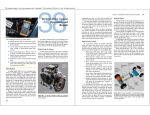
Introducing Your Print System
In addition to its standard features, listed in
User's Guide, you can add
the following options to expand your printing capabilities.
CD-ROM
PAPER FEEDER PF-98B
For high volume printing
of up to 550 sheets in a
single paper size.
RAM DIMMs (memory)
For memory expansion.
Available in 128 MB,
256 MB, and 512 MB
DIMMs. It is
recommended that you
should use Canon
Expansion RAM ER128A, ER-256A, or ER512A as the expansion
RAM.
PS ROM A-98C
By installing PS ROM,
"PostScript 3 Emulation"
which makes it possible to
print with PostScript is
available.
Also, by installing a hard
disk and expansion RAM
module (256 MB or more),
you can print PDF files
using the direct print
function.
PS/Barcode ROM A-98B
By installing PS/Barcode
ROM, the bar code fonts
are also available as well
as the functions of PS
ROM.
Hard Disk Kit HD-98B
Installing Hard Disk Kit HD-98B allows
you to save received print jobs and to
use various printing functions such as
the secured print function.
12
NB-W2
By installing NB-W2, wireless LAN
communication is available (compatible
with IEEE802.11b and IEEE802.11g, and
available for communication of up to 54
Mbps transmission speed by wireless).
Additionally, the security functions
compatible with WEP, IEEE802.1X/EAP
(TLS/TTLS/PEAP), PSK, and WPA
(AES) are supported.
IMPORTANT
Taking the Printer Out of
the Package and
Installing the Printer
Step1
The supplied CD-ROM does not include the printer driver for Macintosh.
Download the printer driver for Macintosh that supports this printer from
the Canon website. If you cannot find the printer driver for Macintosh that
supports this printer on the Canon website, contact your local authorized
Canon dealer.
NOTE
• This printer does not come with a USB cable. Have an appropriate one
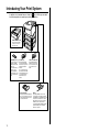
Confirming the Contents of the Box
available for the computer you are using. Use a USB cable with the
following symbol.
Make sure that all the following items are contained in the package before
installing the printer. If any item is missing or damaged, please contact your
local authorized Canon dealer.
• Canon Font Manager is included in the [Canonfm] folder on the User
Manual CD-ROM.
• 127 PS fonts for Macintosh are included in the User Manual CD-ROM.
Printer
The following parts are
already installed.
• Paper cassette
• Fixing unit
• Waste toner container
• Staple cartridge
(LBP5975 only)
Power cord
(The form of the
supplied power cord
may differ from the one
in the above illustration.)
Drum cartridge X 4
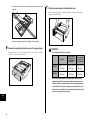
After securing an installation site, take the printer out of the package and carry
it to the installation site.
Getting Started Guide
(This Manual)
Paper size indicator
IMPORTANT
• Install the printer on a platform such as a desk that can easily support the
A4
A5
B4
11x17
B5
LTR
EXEC
weight of the printer.
A3
• Do not install the printer on a platform that may warp from the weight of the
LGL
Paper size labels
Carrying the Printer to the Installation Site
Replacement staple
cartridges (a set of three)
(LBP5975 only)
printer and optional accessories, or where the printer is liable to sink (such
Toner cartridge X 4
as a carpet or mat).
• When installing the optional paper feeder, install it at the installation site
before taking the printer out of the package. For details on installing the
paper feeder, see "Installing a Paper Feeder," on p. 51.
User Manual CD-ROM
• Manuals
- User's Guide
- Remote UI Guide
- Network Guide
• Canon Font Manager
(Windows only)
• PS Fonts (Macintosh only)
User Software CD-ROM
• Printer Driver
• Driver Guide
13
Step
1
1
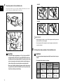
Step
1
- LBP5975
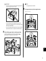
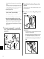
Carry the printer to the installation site.
Carry the printer with 4 or more people by holding the lift handles on the lower
portion of the printer and lifting it up at the same time.
- LBP5970
IMPORTANT
• When taking out the printer, secure sufficient space around the printer and
take it out with four or more people.
• Carry the printer with the tape that secures the paper cassette or front
cover etc. attached.
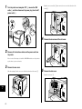
2
Put the printer down carefully at the installation site.
CAUTION
CAUTION
• The printer weight is approximately 115.7 lb (52.5 kg) for LBP5975
• Put the printer down slowly and carefully. Be careful not to hurt your
and approximately 106.9 lb (48.5 kg) for LBP5970 without the toner
cartridges and drum cartridges installed. The printer must be carried
by 4 or more people, and care must be taken to avoid hurting your
hands.
• The weight of the printers is as follows.
back or other portions of your body when carrying the printer.
Default
• Be sure not to hold the printer by the paper cassette, output area, or
any portions other than the lift handles. If you do so, you may drop
the printer, resulting in personal injury.
14
With the toner
cartridges and
drum cartridges
installed
With the optional
paper feeders (3
units) installed
LBP5975
Approx. 115.7 lb Approx. 135.4 lb Approx. 208.1 lb
(52.5 kg)
(61.4 kg)
(94.4 kg)
LBP5970
Approx. 106.9 lb Approx. 126.5 lb Approx. 199.3 lb
(48.5 kg)
(57.4 kg)
(90.4 kg)
Be sure to install the printer on a sturdy platform that can easily
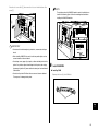
1
install the printer in unstable locations, such as unsteady platforms
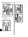
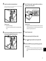
Remove the tape attached to the printer. You will remove the
tape (A) later.
or inclined floors, in locations subject to excessive vibrations, or on
• LBP5975 (7 locations)
support the weight of the printer and optional accessories. Do not
the upper row of a computer rack, as this may cause the printer to fall
or tip over, resulting in personal injury.
(A)
IMPORTANT
Secure sufficient space around the printer at the installation site so that
you can install the optional accessories and connect cables.
Removing the Packing Materials
This printer is provided with tape and packing materials to be protected from
excessive vibrations and shocks during delivery. Remove the tape and packing
b
materials after the printer is carried to the installation site.
IMPORTANT
• If there is any packing material remaining inside the printer, this may result
in poor print quality or damage to the printer when operating the printer. Be
a
sure to remove all the packing materials following the procedure.
• The removed packing materials are required when transporting the printer
for relocation or maintenance. Keep them where they will not get lost.
NOTE
The packing materials may be changed in form or position to be placed, or
may be added or removed without notice.
15
Step
1
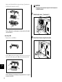
• LBP5970 (6 locations)
Step
1
2
If you are using LBP5975, remove the packing material
attached with tape.
(A)
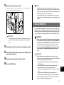
3
Open the front cover.
While pressing the lever on the right side of the front cover, open the front cover
toward you.
IMPORTANT
Dispose of the packing materials according to local regulations.
NOTE
Remove the tape that secures the rear cover while supporting the rear
cover by hand as shown in the figure.
IMPORTANT
Before opening the front cover, make sure that the multi-purpose tray and
the paper cassette of the printer are closed.
16
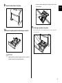
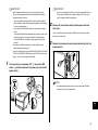
4
5
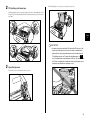
Tilt the fixing unit toward you.
While pressing the green lock release buttons (A) on the left and right side of the
fixing unit a, hold the tabs (B) and the fixing unit toward you b as shown in the
figure.
Pull out the string-attached metal bars of the fixing unit by
the string.
(A)
a
a
(B)
b
6
While holding the tabs (A), move the fixing unit back to its
original position a, and then press the tabs on the both
sides as shown in the figure b.
(A)
IMPORTANT
a
Remove the string-attached metal bars of the fixing unit using the following
procedure. Do not remove the string-attached metal bars when the fixing
unit is not tilted toward you.
b
b
17
Step
1
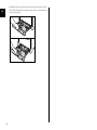
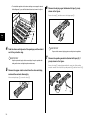
7
Step
1
Close the front cover.
While supporting the front cover a, push and close the front cover with both
hands as shown in the figure b.
8
Pull out the paper cassette.
Pull the paper cassette out until it stops a.
a
a
After lifting the paper cassette up a little b, pull it out while supporting it with the
other hand c as shown in the figure.
b
b
CAUTION
Push the front portion of the front cover to close it as shown in the
figure. If closing the front cover by the levers on the both sides, you
may catch your fingers, resulting in personal injury.
c
IMPORTANT
The paper cassette cannot be pulled out horizontally. If you try to pull it out
forcefully, this may result in damage to the paper cassette.
18
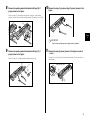
9
Remove the tape shown in the figure.
• Do not touch the black rubber pad (A) in the paper cassette. This may
result in misfeeds.
Step
1
(A)
11 Set the paper cassette in the printer.
10 Remove the packing material inside the paper cassette.
While holding the paper cassette with both hands, insert it until it stops a as
shown in the figure.
a
IMPORTANT
• A packing material is attached to the paper cassette. Be sure to pull out
the paper cassette and remove the packing material.
19
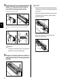
After lifting the front of the paper cassette up a little b, push the paper cassette
into the printer firmly until the front side of the paper cassette is flush with the front
surface of the printer c.
Step
1
b
c
20
2
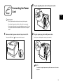
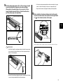
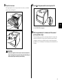
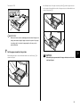
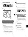
Step2
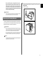
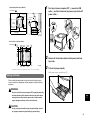
Plug the supplied power cord into the power socket.
Connecting the Power
Cord
Step
2
IMPORTANT
• One AC power outlet should be used exclusively for the printer.
• Do not plug the power plug into the auxiliary outlet on a computer.
• Do not connect this printer to an uninterruptible power source. This may
cause printer malfunction or breakdown at the occurrence of a power
failure.
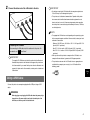
1
Make sure that the power switch of the printer is OFF.
The printer is OFF when "
" of the power switch is pressed.
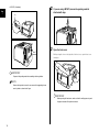
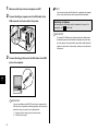
3
Plug the power plug into the AC power outlet.
Put the power cord through the concavity as shown in (A).
(A)
NOTE
The form of the supplied power cord may differ from the one in the above
illustration.
21
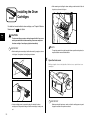
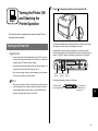
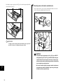
• When removing or installing the drum cartridges, work from the left side of
the printer as shown in the figure.
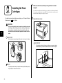
Installing the Drum
Cartridges
Step3
For details on how to handle the drum cartridges, see "Chapter 6 Routine
Maintenance" in
User's Guide.
CD-ROM
CAUTION
Step
3
The drum cartridge generates a low level magnetic field. If you use a
cardiac pacemaker and feel abnormalities, please move away from
the drum cartridge. Consult your physician immediately.
NOTE
IMPORTANT
The packing materials may be changed in form or position to be placed, or
• When handling a drum cartridge, hold the blue tabs (A) properly as shown
may be added or removed without notice.
in the figure. Do not place it vertically or upside-down.
(A)
1
Open the front cover.
While pressing the lever on the right side of the front cover, open the front cover
toward you.
(A)
IMPORTANT
• A drum cartridge comes in a protective bag. Do not take the drum
cartridge out of the protective bag until the drum cartridge is ready to be
set.
22
Before opening the front cover, make sure that the multi-purpose tray and
the paper cassette of the printer are closed.
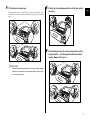
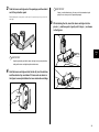
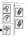
2
While holding the lever of the top cover, open the top cover.
Tilt the fixing unit toward you.
While pressing the green lock release buttons (A) on the left and right side of the
fixing unit a, hold the tabs (B) and tilt the fixing unit toward you b as shown in
the figure.
(A)
a
a
(B)
b
Step
3
IMPORTANT
• Do not touch the transfer belt of the ITB unit and the ITB unit cover. If the
transfer belt is damaged, this may result in misfeeds or deterioration in
print quality. If the print quality deteriorates due to the transfer belt of the
ITB unit being touched, see "Chapter 6 Routine Maintenance" in
CD-ROM
User's Guide and clean the transfer belt of the ITB unit. The transfer belt of
the ITB unit is supplied with a function that cleans itself, therefore, you do
3
not need to clean the belt even when toner is on it.
Open the top cover.
Press the blue lock release button of the top cover.
Do not touch
these parts.
23
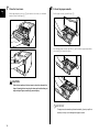
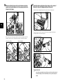
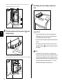
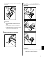
• The installation positions of the drum cartridges are arranged in order of
Yellow, Magenta, Cyan, and Black from the back as shown in the figure.
6
Remove the drying agent attached with tape (1 piece)
shown in the figure.
Remove the tape a, and then remove the drying agent b.
a
Yellow
Magenta
b
Cyan
Step
3
Black
4
Dispose of the removed drying agent according to local regulations.
7
IMPORTANT
Keep the protective bag for the drum cartridge. It may be required after
taking out the drum cartridge for printer maintenance.
5
IMPORTANT
Take the drum cartridge out of the package, and then take it
out of the protective bag.
Remove the packing material attached with tape (A) (1
piece) shown in the figure.
Remove the tape a and packing material at the same time. If the packing
material cannot be removed, tilt the packing material b, and then remove it c.
Remove the paper caution sheet from the drum cartridge,
and read the contents thoroughly.
After removing the tape a, remove the sheet b.
b
a
a
b
(A)
24
c
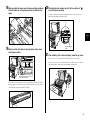
8
Remove the packing material attached with tape (B) (1
piece) shown in the figure.
10 Remove the tape (1 piece) and tags (2 pieces) shown in the
figure.
Remove the tape a and packing material at the same time. If the packing
material cannot be removed, tilt the packing material b, and then remove it c.
a
(B)
c
b
Step
3
IMPORTANT
Dispose of the packing materials according to local regulations.
9
Remove the packing material attached with tape (C) (1
piece) shown in the figure.
Remove the tape a, and then pull the packing material out b.
a
(C)
b
11 Remove the tape (3 pieces) shown in the figure in order of
a and b.
The tape to be removed in b has another tape attached to the rear end. Remove
them together.
Remove this tape also.
a
b
25
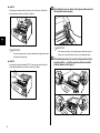
12 Hold the blue tabs (A) of the drum cartridge and shake it up
and down 10 to 12 times each as shown in the figure to
evenly distribute the developer inside the cartridge.
IMPORTANT
• When placing the drum cartridge, be sure to place paper under the drum
cartridge to prevent a desk or others from being damaged by the bottom of
the drum cartridge.
Hold the blue tabs of the drum cartridge.
• When pulling the sealing tape out, do not hold the area near the mouth of
(A)
the sealing tape with your hand. If the tape is severed, it may become
difficult to pull out completely.
Do not hold this part
with your hand.
(A)
Step
3
Shake the drum cartridge up and down 10 to 12 times each as shown in the
figure.
• When pulling the sealing tape out, be careful not to hold the drum
protective shutter (A) with your hands.
(A)
IMPORTANT
If the developer is not distributed evenly, this may result in deterioration in
print quality. Be sure to carry out this procedure properly.
13 Place paper on a flat surface, place the drum cartridge on it,
and then fold back the tab (A) of the sealing tape as shown
in the figure.
(A)
26
14 Pull the sealing tape (approx. 28 in. (70 cm) long) out gently
and horizontally while supporting the drum cartridge.
When pulling the sealing tape out, you may feel it to be
heavy. However, because this is not printer malfunction,
pull the sealing tape out completely.
Support this part with your hand.
• Pull out the sealing tape completely from the drum cartridge. If any tape
remains in the drum cartridge, this may result in poor print quality.
• Dispose of the removed sealing tape according to local regulations.
15 Before installing the drum cartridge, align the triangular
mark on the lock release lever (A) with the triangular mark
of "
" on the label as shown in the figure.
Step
3
Align the triangular marks.
(A)
When installing the drum cartridge, hold the blue tabs as shown in the figure.
IMPORTANT
• If it is difficult to pull the sealing tape out by the tab, hold the tape and pull
it out as shown in the figure. However, your hands may become dirty as
toner is on the sealing tape.
• Do not pull the sealing tape diagonally, upwards, or downwards. If the tape
is severed, it may become difficult to pull out completely.
27
16 Make sure that the levers (A) near the drum cartridge
guides on the both sides are in the proper position as
shown in the figure.
17 Install the drum cartridges in the printer unit in order of
Black (K), Cyan (C), Magenta (M), and Yellow (Y).
Insert the drum cartridge firmly until it touches the back of the printer.
Step
3
(A)
(A)
Insert the projections (A) on each side of the drum cartridge into the drum
cartridge guides as shown in the figure.
If the levers are not in the proper position, the drum cartridges cannot be
installed. Raise the levers to the proper position as shown in the figure.
• Incorrect position
• Correct position
- Drum cartridge guides (left)
Yellow
Magenta
Cyan
Black
(A)
- Drum cartridge guides (right)
Yellow
Magenta
Cyan
Black
(A)
IMPORTANT
Insert the drum cartridges firmly until they touch the back of the printer. If
the drum cartridges are not installed firmly, this may result in poor print
quality.
28
18 Make sure that the levers near the drum cartridge guides on 20 Slide the blue lock release lever (A) to the position of "
the both sides are in the proper position as shown in the
figure.
"
to lock the drum cartridge.
Slide the lock release lever until the triangular mark on the lock release lever
aligns with the triangular mark on the label.
(A)
Step
3
Align the triangular
marks.
19 Make sure that the labels on the projections of the drum
cartridge are visible.
21 After installing all the drum cartridges, close the top cover.
Close the top cover of the printer while holding it by the lever (A) gently.
If you close the top cover forcefully, the ITB unit cover (B) may not move back to
the original position, and this may result in damage to the printer.
(B)
Make sure that all of the three colors
on the label are visible.
If you cannot see any of the three colors on the label from the front, take out the
drum cartridge once, turn the projection (A) in the direction of the arrow until it
clicks and stops, and then reinstall the cartridge.
(A)
(A)
29
● LBP5975
By pressing the top cover with both hands, close it firmly until it cannot be
pressed down any further as shown in the figure.
22 By holding the lever as shown in the figure, make sure that
the top cover does not open.
Step
3
IMPORTANT
To close the top cover, press the areas (both ends of the protrusion) shown
in the figure with both hands.
● LBP5970
By pressing the portion indicated "PUSH", close the top cover firmly until it
cannot be pressed down any further as shown in the figure.
IMPORTANT
Close the top cover firmly until it cannot be pressed down any further. If
the top cover is not closed firmly, this may result in poor print quality.
23 While holding the tabs (A), move the fixing unit back to its
original position a, and then press the tabs on the both
sides as shown in the figure b.
(A)
a
b
30
b
24 Close the front cover.
25 Press " " of the power switch to turn the printer ON.
While supporting the front cover a, push and close the front cover with both
hands as shown in the figure b.
a
Step
3
<14 CHK TNR/COVER> is displayed.
26 Wait for approximately 3 to 4 minutes until the sound of
b
printer operations stops.
The drum cartridges are ready to be used in approximately 3 to 4 minutes after
the printer is turned ON. The sound of printer operations stops when the drum
cartridges are ready to be used. Wait for 4 minutes or longer after turning the
power ON. Then, see "Installing the Toner Cartridges" (p. 32) and install the toner
cartridges.
CAUTION
Push the front portion of the front cover to close it as shown in the
figure. If closing the front cover by the levers on the both sides, you
may catch your fingers, resulting in personal injury.
31
1
Step4
Installing the Toner
Cartridges
For details on how to handle the toner cartridges, see "Chapter 6 Routine
Maintenance" in
User's Guide.
Make sure that the sound of printer operations has been
stopped.
After the drum cartridges are installed, they are ready to be used in approximately
3 to 4 minutes after the printer is turned ON. The sound of printer operations stops
when the drum cartridges are ready to be used.
2
Open the toner cover.
CD-ROM
CAUTION
Take care not to allow the toner to come into contact with your hands
or clothing, as this will dirty your hands or clothing. If they become
dirty, wash them immediately with cold water. Washing with warm
water will set the toner and make it impossible to remove the toner
Step
4
stains.
IMPORTANT
When handling a toner cartridge, hold the tabs (A) as shown in the figure.
IMPORTANT
The installation positions of the toner cartridges are arranged in order of
(A)
Yellow, Magenta, Cyan, and Black from the back as shown in the figure.
Yellow
Magenta
Cyan
Black
(A)
NOTE
The packing materials may be changed in form or position to be placed, or
may be added or removed without notice.
32
3
IMPORTANT
Take the toner cartridge out of the package, and then take it
out of the protective pack.
If toner is not distributed evenly, this may result in deterioration in print
quality. Be sure to carry out this procedure properly.
While holding the center portion on the top of the protective pack, open it to left
and right.
5
While holding the tab, insert the toner cartridge into the
printer a, and then push it gently until it stops b as shown
in the figures.
Step
4
a
IMPORTANT
Keep the protective pack for the toner cartridge. It may be required after
taking out the toner cartridge for printer maintenance.
4
Hold the toner cartridge so that the tab (A) is at the bottom,
and then shake it up and down 10 times each as shown in
the figure to evenly distribute the toner inside the cartridge.
b
(A)
33
Insert the toner cartridge so that the orientation of the character on the toner
cartridge and that on the toner cover match.
7
After installing all the toner cartridges, close the toner
cover.
Top View
Match the orientation
of the characters.
Step
4
6
Tilt the lock release lever (A) to the position of "
the toner cartridge.
" to lock
IMPORTANT
• If you cannot close the toner cover, check if the toner cartridges are
installed properly. If you try to close the toner cover forcefully, this may
result in damage to the printer or toner cartridges.
(A)
• Do not leave the toner cover open for a long time after installing the toner
cartridge.
• When removing a toner cartridge, tilt the lock release lever of the toner
cartridge to the position of "
" to release the lock before you remove the
toner cartridge.
NOTE
If <CHG."color" TNR> ("color" indicates K, Y, M, or C) appears after
installing the toner cartridges, remove the toner cartridge of the indicated
Align the triangular mark on the lock release lever with that on the toner cartridge.
color, hold the toner cartridge so that the tab is at the bottom, shake the
cartridge up and down forcefully again to evenly distribute the toner inside
Top View
the cartridge, and then install the toner cartridge ("K", "Y", "M", and "C"
indicate Black, Yellow, Magenta, and Cyan respectively).
Align at this point
34
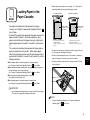
• Before loading long size paper such as Ledger (11 x 17) and Legal in
portrait orientation, adjust the length of the paper cassette.
Step5
Loading Paper in the
Paper Cassette
Portrait orientation
For details on handling the multi-purpose tray or paper
cassette, see "Chapter 3 Loading and Outputting Paper" in
User's Guide.
By default, this printer feeds paper from two paper sources: the
paper cassette (Cassette 1) and multi-purpose tray. Also,
paper can be fed from up to 5 paper sources by installing the
optional paper feeders (Cassette 2, Cassette 3, and Cassette
4).
This section only describes the procedure for loading plain or
paper of standard size in Cassette 1. When loading paper
other than plain paper or when using the multi-purpose tray or
paper feeder (Cassette 2, Cassette 3, and Cassette 4), see the
following directions.
When loading
Letter size
paper
When loading
Ledger (11 x 17)
size paper
CD-ROM
● When loading labels or custom size paper in the paper cassette
See "Chapter 3 Loading and Outputting Paper" in
User's Guide
Landscape orientation
- Paper that can be loaded in
portrait orientation
A3, B4, Ledger (11 x 17), and
Legal
- Paper that can be loaded in
landscape orientation
A4, B5, A5, Letter, and Executive
• Do not pull out the paper cassette while the printer is printing. This may
result in paper jams or damage to the printer.
• Refill the cassette after paper runs out. If the cassette is refilled when
paper still remains in the cassette, it may result in misfeeds.
Step
5
• Do not touch the black rubber pad (A) in the paper cassette. This may
result in misfeeds.
CD-ROM
● When loading plain paper, coated paper, heavy paper, labels, envelopes, or
custom size paper in the multi-purpose tray
See "Chapter 3 Loading and Outputting Paper" in
User's Guide
(A)
CD-ROM
● When installing the optional paper feeders in the printer
See Installing a Paper Feeder: p. 51
● When loading paper in the paper cassette of a paper feeder
See "Chapter 3 Loading and Outputting Paper" in
User's Guide
CD-ROM
IMPORTANT
• Do not load paper with jagged edges, creased, or extremely curled paper.
This may result in paper jams or damage to the printer.
NOTE
For more details on printable paper, see "Chapter 3 Loading and
Outputting Paper" in
CD-ROM
User's Guide.
35
1
IMPORTANT
Pull out the paper cassette.
The paper cassette cannot be pulled out horizontally. If you try to pull it out
Pull the paper cassette out until it stops a.
forcefully, this may result in damage to the paper cassette.
2
a
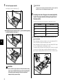
According to the size of the paper to be loaded, adjust the
length of the paper cassette and change the positions of
the paper guides.
The paper sizes indicated on the paper guides are abbreviated as follows.
Paper Size
● After lifting the paper cassette up a little b, pull it out while supporting
it with the other hand in the figure c.
Paper Guides
Ledger
11 x 17
Legal
LGL
Letter
LTR
Executive
EXEC
● Adjust the length of the paper cassette according to the size of the
paper to be loaded.
b
Step
5
When loading paper in landscape orientation, such as when loading A4, B5, A5,
Letter, or Executive size paper, shorten the paper cassette.
When loading paper in portrait orientation, such as when loading A3, B4, Ledger
(11 x 17), or Legal size paper, extend the paper cassette.
To adjust the length of the paper cassette, push up the lock release levers gently
to release the lock, slide the paper cassette by holding the rear portion of the
paper cassette, and then push down the lock release levers to lock the cassette.
Side View Release
Release
c
Lock
Lock
Side View
CAUTION
Be sure to take the paper cassette out of the printer before loading
paper. If paper is loaded while the paper cassette is partially pulled
out, the paper cassette may drop or the printer may become
damaged resulting in personal injury.
36
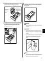
● While holding the lock release lever of the rear paper guide a, slide the
guide to the mark for the size of the paper to be loaded b.
a
3
Load the paper stack so that the rear edge is aligned with
the paper guide.
If the paper size is
indicated on the right,
align this point to the size
of the paper to be loaded.
If the paper size is
indicated on the left,
align this point to the
size of the paper to
be loaded.
b
● While holding the lock release lever of the side paper guides a, slide
the guides to the mark for the size of the paper to be loaded b.
The side paper guides move together.
Top View
Align this part
with the size of
the paper to be
loaded.
CAUTION
When loading paper, take care not to cut your hands with the edges
of the paper.
Top View
IMPORTANT
• Be sure to check if the paper guide is at the position of the size of the
loaded paper. If the paper guide is set at a wrong position, this may result
a
in misfeeds.
• If you use paper that has been poorly cut, multiple sheets of paper may be
fed at once. In this case, align the edges of the stack on a hard, flat
surface.
b
NOTE
To print letterhead paper or paper printed with a logo, load the paper in the
proper orientation according to the following instructions:
37
Step
5
- When loading paper in landscape orientation, such as when loading A4,
B5, A5, Letter, or Executive size paper, load the paper so that the
printing side is facing up as shown in the following figures.
(
: Feeding direction)
IMPORTANT
Up to approximately 230 sheets of plain paper (20.0 lb Bond (80 g/m2))
can be loaded in a paper cassette. Be sure that the paper stack does not
exceed the load limit marks (B) on the paper guides. If the paper stack
exceeds the load limit marks, this may result in misfeeds.
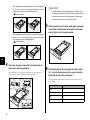
5
Attach the label for the size of the loaded paper to the paper
size indicator, and then insert the indicator into the paper
size slot at the front of the paper cassette.
- When loading paper in portrait orientation, such as when loading A3, B4,
Ledger (11 x 17), or Legal size paper, load the paper so that the printing
side is facing up as shown in the following figures.
(
: Feeding direction)
Step
5
4
Press down the paper stack so that it is loaded under the
hooks on the side paper guides (A).
Make sure that there is sufficient space between the hooks and paper stack. If
there is no sufficient space, slightly reduce the amount of paper.
(A)
(A)
6
While holding the tab (B) on the paper size setting switch
(A) a, align the triangular mark on the paper size setting
switch with the size of the loaded paper b.
The following shows the abbreviations of paper sizes that are marked on the
paper cassette.
Paper Size
Paper Size Setting Switch of a Paper Cassette
(B)
(B)
38
Ledger
11 x 17
Legal
LGL
Letter
LTR
Executive
EXEC
After lifting the front of the paper cassette up a little b, push the paper cassette
into the printer firmly until the front side of the paper cassette is flush with the front
surface of the printer c.
The default is "LTR".
(B)
a
b
b
(A)
IMPORTANT
Make sure that the size of the loaded paper matches that of the paper size
setting switch before setting the paper cassette in the printer. If the paper
size setting switch is not set to the proper position, this may result in
c
printer malfunction.
7
Set the paper cassette in the printer.
While holding the paper cassette with both hands, insert it until it stops a as
shown in the figure.
Step
5
CAUTION
When setting the paper cassette in the paper feeder, be careful not to
catch your fingers.
a
39
IMPORTANT
Step6
Connecting to a
Computer
If more than one devices are connected to an AppleTalk network, turn on
each device at an interval of ten seconds or longer.
NOTE
• This printer recognizes the type of Ethernet (100BASE-TX or 10BASE-T)
automatically.
This section describes how to connect the printer to a computer and
network.
This printer is equipped with a LAN connector and USB connector.
• If both 100BASE-TX devices and 10BASE-T devices are on the same
network, a device such as a switching hub that supports both 100BASETX and 10BASE-T is required. For more details, contact your local
authorized Canon dealer.
• If you connected this printer to a network, check the MAC address of the
Using a LAN Cable
print server with Configuration Page Print, and then configure the network
operating system (UNIX, etc.) and print server. For more details, see " CD-ROM
By connecting the printer to a network such as Ethernet to be shared on the
Network Guide".
network, you can use the printer from a computer on the network. You can use
UNIX, Windows, Mac OS, and other operating systems.
This printer includes a print server that supports 10BASE-T/100BASE-TX and
is compatible with the TCP/IP, NetWare, AppleTalk (EtherTalk), and SMB
protocols.
Connect the LAN connector on this printer and a hub port with a Category 5
twisted pair cable. Have cables or a hub ready as needed. For compatible
cables and hubs, contact your local authorized Canon dealer.
Step
6
Computer with
10BASE-T Connector
Computer with
100BASE-TX Connector
Ethernet Cable
LAN Connector
Hub
CAUTION
Before connecting the network cable to the printer, be sure to turn
the printer OFF, and then unplug the power plug from the AC power
outlet. Failure to observe these steps may result in an electrical
shock.
40
1
Connect the LAN cable to the LAN connector.
Connect a LAN cable that is compatible with the LAN connector of the network
board according to the network.
2
Connect the other end of the LAN cable to the hub.
IMPORTANT
• Do not plug or unplug the USB cable while the computer and printer are
ON, as this may result in damage to the printer.
• This printer uses bi-directional communication. Operation of the printer
when connected via unidirectional communication equipment has not
been tested, and as a result, Canon cannot guarantee printer operation
when the printer is connected using unidirectional print servers, USB hubs
or switching devices.
NOTE
• The appropriate USB interface varies depending on the operating system
of the connected computer as follows. For more details, contact your local
authorized Canon dealer.
● Installing the Software
After connecting the LAN cable, install the software for this printer. For
more details, see "
Driver Guide".
CD-ROM
IMPORTANT
The supplied CD-ROM does not include the printer driver for Macintosh.
Download the printer driver for Macintosh that supports this printer from
the Canon website. If you cannot find the printer driver for Macintosh that
supports this printer on the Canon website, contact your local authorized
- Windows 2000/XP/Server 2003/Vista: USB 2.0 Hi-Speed/USB FullSpeed (USB1.1 equivalent)
- Mac OS X 10.3.2 or earlier: USB Full-Speed (USB 1.1 equivalent)
- Mac OS X 10.3.3 or later: USB 2.0 Hi-Speed/USB Full-Speed (USB1.1
equivalent)
• When you connect this printer to a computer with a USB cable, use a
computer with manufacturer's guarantee of USB proper operation.
• This printer does not come with a USB cable. Have an appropriate one
available for the computer you are using. Use a USB cable with the
following symbol.
Canon dealer.
Step
6
Using a USB Cable
Connect the printer to a computer equipped with a USB port using a USB
cable.
WARNING
When plugging or unplugging the USB cable when the power plug is
plugged in an AC power outlet, do not touch the metal part of the
connector, as this may result in electrical shock.
41
1
Make sure that the printer and computer are OFF.
NOTE
If you are not sure about the USB cable that is supported by the computer
2
you are using, contact the store where you purchased the computer.
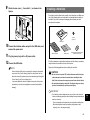
Connect the B-type (square) end of the USB cable to the
USB connector on the rear side of the printer.
● Installing the Software
After connecting the USB cable, install the software for this printer. For
more details, see "
Driver Guide".
CD-ROM
IMPORTANT
The supplied CD-ROM does not include the printer driver for Macintosh.
Download the printer driver for Macintosh that supports this printer from
the Canon website. If you cannot find the printer driver for Macintosh that
supports this printer on the Canon website, contact your local authorized
Canon dealer.
3
Connect the A-type (flat) end of the USB cable to the USB
port on the computer.
Step
6
IMPORTANT
If you are using Windows and LBP5975 connected to a computer with a
USB cable, be sure to perform the following procedure after installing the
printer driver. If not, you cannot use the stapling function.
1. Display the [Device Settings] sheet in the printer driver.
2. Click [Get Device Status].
42
1
Step7
Press " " of the power switch to turn the printer ON.
Turning the Printer ON
and Checking the
Printer Operation
This section describes the procedures for turning the printer ON and
checking the printer operation.
Turning the Printer ON
IMPORTANT
• Do not turn the printer ON immediately after turning it OFF. If you want to
turn the printer ON again after turning it OFF, wait at least 10 seconds after
The indicators and display on the control panel come on, and the printer initiates a
self-diagnostic test on the printer unit and optional accessories.
If no abnormality is found during the self-diagnostic test, the Online indicator,
Ready indicator and Paper Source indicator for the currently selected paper source
come on, <00 READY> appears in the display, and the printer is ready to print.
Online
Cancel Job
Job
Utility
turning the printer OFF before turning it ON again.
• If the printer does not operate properly or an error message appears, see
Ready Message
HDD
Job
ON for the first time after you install the printer.
NOTE
When you turn the power ON for the first time after you install a hard disk
or when a problem has occurred to the hard disk, the printer is ready to
print after approximately 60 seconds after it is turned ON because the
Power
Main Power
Reset
"When the Printer Does Not Operate Properly," on p. 45.
• Be sure to set the paper cassette in the printer before you turn the power
Settings
OK
Feeder Selection
Online
Indicator
Paper Source Ready
Indicators
Indicator
The following information is displayed in the display.
Printable and not
processing print data
00
READY
LT
Size of paper in the
currently selected
paper source
Step
7
hard disk is formatted after the printer is turned ON.
43
Checking the Operations with
Configuration Page Print
Before using the printer for the first time, be sure to perform Configuration Page
Print to check the operations using the following procedure. Configuration Page
Print prints printer information such as a list of the menu settings and the
number of the total print pages.
OK
4
Press [OK].
CONFIG.PAGE
→
EXECUTING
CONFIG.PAGE
(Approx. 1 sec.)
→
Configuration Page Print is printed.
NOTE
• Configuration Page Print is designed to be printed on Letter size paper.
Although Configuration Page Print can be printed on another size of paper,
it will be printed with its size enlarged or reduced, with a portion of the
page not printed, or with its printing position being skewed.
• The settings specified using the menu of the printer's control panel are
reflected to Configuration Page Print. For example, when the automatic 2-
Contents of Configuration Page Print
Configuration Page Print prints information as shown in the following figure.
Configuration Page Print allows you to confirm information such as a list of
the setting values specified in the printer function menu, the versions of the
software and hardware equipped with the printer, and number of the total
print pages. You can check the number of total print pages using "Page
Count" on the lower right of Configuration Page Print.
sided printing function is specified, Configuration Page Print will be printed
with two pages on both sides of paper. However, always a sheet of paper
is printed regardless of the number of copies.
IMPORTANT
This is a sample of Configuration Page Print. The contents may partially
differ from the Configuration Page Print printed by your printer.
1
Online
2
Press " " of the power switch to turn the printer
ON.
Make sure that the printer is online.
If the printer is not online, press [Online].
Step
7
Utility
3
Press [Utility].
UTILITY MENU
CONFIG.PAGE
→
CONFIG.PAGE is displayed in the display.
44
When the Printer Does Not Operate
Properly
Symptom
A paper jam occurs each
time you print.
If the printer does not operate even after turning it ON or print Configuration
Page Print properly, the following causes are conceivable.
Symptom
The printer cannot be
turned ON.
Cause
Remedy
The power plug is
unplugged from the AC
power outlet.
Plug the power plug into
the AC power outlet.
There is a break in the
power cord.
If the printer is turned ON
after replacing the power
cord with the one that is of
the same type and is used
for other device, there is a
break in the power cord. In
this case, purchase a new
power cord and replace it
with the broken one.
The indicators on the
control panel do not come
on.
The printer is not ON.
Turn the printer ON.
The printer is in Power
Save Mode.
The printer will be ready to
print after you send print
data or press any key on
the control panel.
The printer does not
operate.
The printer is offline.
Press [Online] to turn on
the Online indicator.
The interface cable is
disconnected.
Connect the interface cable
firmly to the interface
connectors on the
computer and printer unit.
Nothing is printed on the
paper.
The Message indicator is
on and a message is
displayed in the display.
Cause
Remedy
The amount of the paper
loaded in the paper
cassette or multi-purpose
tray exceeds the load
limitation.
Reduce the amount of
paper to within the load
limitation and print again.
Paper is not loaded
properly in the paper
cassette or multi-purpose
tray.
Load the paper properly
and print again.
Unusable paper is loaded
in the paper cassette or
multi-purpose tray.
Replace the paper with one
that can be used and print
again.
There is still jammed paper
inside the printer.
Remove any jammed
paper and print again.
Multiple sheets of paper
were fed at a time.
Align the paper stack in the
paper cassette or multipurpose tray properly and
load it again. If you are
using coated paper or
labels, fan them thoroughly
and load them again.
Any drum cartridge was
installed with the sealing
tape still attached.
Take the drum cartridge out
of the printer, pull out the
sealing tape, and then
reinstall the drum cartridge.
Some problem has
occurred.
See "Chapter 7
Troubleshooting" in CD-ROM
User's Guide and solve the
problem.
Changing the Language Used in the
Display
Step
7
The default value of the language used in the display is [ENGLISH].
You can change the display language to [FRENCH], [GERMAN], [ITALIAN], or
[SPANISH] using the following procedure.
45
Settings
1
Press [Settings].
Turning the Printer OFF
SETUP
CONTROL MENU
Utility
2
Settings
Turn the printer OFF using the following procedure. The procedure for turning
the printer OFF is different between when a hard disk is used and when it is not
→
Select CONTROL MENU using [
press [OK].
used.
] and [
], then
IMPORTANT
• When using the hard disk, be sure to turn the printer OFF as the
procedure for the protection of the hard disk. (See p. 46)
CONTROL MENU
OK
→
• If the printer is connected to a network, make sure that other computers
are not sending print data to the printer before turning the printer OFF.
POWER SAVE MODE→
• If you turn the printer OFF when the Job indicator is on, all the print data
remaining in the printer memory will be erased. If there is any necessary
Utility
3
Settings
Select PANEL LANGUAGE using [
then press [OK].
=ENGLISH
Settings
OK
Step
7
the offline state and then select FORM FEED to output the data before
turning the printer OFF.
• Do not turn the power OFF when the printer is in any of the following
4
status:
- During printing
→
Select the display language using [
then press [OK].
FRENCH
→
=FRENCH
→
The display language is changed.
PANNEAU LANGUES→
46
print data remaining in the printer, wait until it is output, or press [Reset] in
],
PANEL LANGUAGE →
OK
Utility
] and [
- While the printer is running a self-diagnostic test immediately after
turning the power ON
] and [
],
- While a message informing you that the NVRAM is being initialized or
being written is displayed
- While <02 STARTING UP> or <02 CALIBRATING> is displayed
• When you are using a hard disk, make sure that the HDD indicator is not
on. If you turn the printer OFF while the HDD indicator is on (while data is
being read from the hard disk or being written to the hard disk), the hard
disk may be damaged and disabled.
When Not Using a Hard Disk
When you are not using a hard disk, turn the printer OFF using the following
procedure.
1
NOTE
Make sure that the Job indicator is off.
You can also perform SHUT DOWN in the RESET menu by pressing
Online
Cancel Job
Job
Utility
Settings
[Reset] on the control panel. For more details, see "Chapter 5 Printing
Power
Environment Settings" in User's Guide.
OK
Feeder Selection
Ready Message
HDD
Job
Main Power
Reset
1
Off
2
Press "
Make sure that the Job indicator and HDD
indicator are off.
" of the power switch on the printer.
Online
Cancel Job
Job
Utility
Settings
Power
OK
Feeder Selection
Ready Message
HDD
Job
Main Power
Reset
Off
Power
2
Hold down the switch (approximately 4 seconds) until <02
SHUTTING DOWN> is displayed. If the switch is released in less
than 4 seconds, and POWER SAVE MODE is set to a setting value
other than OFF, the printer enters Power Save Mode. (See User's
Guide)
When Using a Hard Disk (Only When a Hard Disk Is
Installed)
02 SHUTTING DOWN
When using the optional hard disk, turn the printer OFF using the following
procedure.
IMPORTANT
• If you perform a shutdown when any job of which you stopped the
operation or of secured print in the hard disk, the message <JOBS
Hold down the control panel power switch (sub
power supply) on the control panel until <02
SHUTTING DOWN> is displayed, then release the
switch.
3
Confirm the message.
Step
7
TURN OFF POWER
REMAIN> is displayed. If you perform a shutdown, all the jobs are deleted.
However, the jobs stored in the boxes are saved in the hard disk as it is.
When you want to continue to print, press [Online] to place the printer
When the printer is ready to be turned OFF after the process for it is
performed, the message <TURN OFF POWER> appears.
online.
• Once you perform a shutdown, you cannot cancel the operation in
midstream. When you want to turn the printer ON again, turn the printer
OFF once following the instruction of the message, and then turn the
printer ON.
47
4
Step
7
48
When the message <TURN OFF POWER> appears, press
" " of the power switch on the printer.
Expansion RAM
Step8
Installing the Optional
Accessories
Optional Accessories
Expansion RAM is an extended memory that expands the amount of memory.
This printer comes with 256 MB of memory. One expansion RAM module can
be added, and the memory capacity can be expanded up to a maximum of
768 MB.
Total RAM Capacity (Expanded RAM
Capacity)
Guaranteed Paper Size for Printing
256 (Standard)
Letter
384 (+ 128 MB)
Ledger (11 x 17)
512 (+ 256 MB)
Legal X 2
768 (+ 512 MB)
Ledger (11 x 17) X 2
The following optional accessories are available in order to make full use of the
printer functions. Purchase them to fulfill your needs. For the optional
accessories, contact your local authorized Canon dealer.
Paper Feeder
In addition to the supplied multi-purpose tray and paper cassette, up to five
paper sources can be used by installing the optional paper feeder.
(+ XX MB) in the table indicates the capacity of the optional expansion RAM
that is required in addition to the standard RAM.
The paper feeder can be loaded with up to approximately 550 sheets of plain
paper (20.0 lb Bond (80 g/m2)) of A3, B4, A4, B5, A5, Ledger (11 x 17),
Legal, Letter, Executive, 8K, 16K and the following custom paper sizes.
The values in the Guaranteed Paper Size for Printing column in the table are
those when performing 1-sided printing with RESOLUTION set to FINE, and
GRADATION LEVEL set to HIGH 1. The paper size is based on the A or B
series paper sizes. The paper sizes (dimensions) are A3, Ledger (11 x 17),
8K, B4, Legal, A4, Letter, 16K, Executive, B5, Envelope B5, Envelope C5, A5,
Envelope COM10, Envelope DL, and Envelope Monarch in descending
dimension order.
- When loading paper in portrait orientation: Width 8.27 to 11.69 in. (210.0 to
297.0 mm); Length 8.27 to 17.00 in. (210.0 to 431.8 mm)
- When loading paper in landscape orientation (Only when UFR II Printer
Driver is used): Width 8.27 to 11.69 in. (210.0 to 297.0 mm); Length 5.83 to
11.69 in. (148.0 to 297.0 mm)
The guaranteed paper sizes for printing vary depending on the settings for
RESOLUTION, GRADATION LEVEL, and 2-SIDED PRINT. on printing.
Calculate the sizes based on the paper sizes in the table above.
Setting
RESOLUTION/
GRADATION LEVEL
Setting Value
Scale Factor
FINE/HIGH 1
100 %
FINE/HIGH 2
50 %
SUPER FINE/STANDARD
50 %
OFF
100 %
ON
50 %
COLOR
100 %
BLACK & WHITE
400 %
PAPER FEEDER PF-98B
2-SIDED PRINT.
IMPORTANT
• Up to 3 paper feeders can be installed.
• PAPER FEEDER PF-98B is designed for LBP5975/5970/5960. You cannot
use a paper feeder designed for other models.
COLOR MODE
Step
8
49
NOTE
Be sure to use a 3.3V DDRAM DIMM compatible with this printer as the
expansion RAM module. It is recommended that you should use Canon
Expansion RAM ER-128A, ER-256A, or ER-512A as the expansion RAM.
DDRAM DIMM (3.3V) compatible with this printer
PS/Barcode ROM A-98B
Usable
Notch
PS ROM
IMPORTANT
Be sure to use PS/Barcode ROM A-98B compatible with this printer.
Hard Disk
By installing PS ROM, "PostScript 3 Emulation" which makes it possible to
print with PostScript is available.
Also, by installing a hard disk and expansion RAM module (256 MB or more),
you can print PDF files using the direct print function.
You can use a hard disk that can be built in the printer to save the received
print jobs temporarily. By installing the hard disk, you can use various
functions such as print job spooling, e-mail print, encrypted secured print,
secured print, electronic sort, and RIP Once.
PS ROM A-98C
IMPORTANT
Be sure to use PS ROM A-98C compatible with this printer.
Hard Disk Kit HD-98B
IMPORTANT
When you are using a hard disk, set MODE TIMEOUT in the SETUP menu
to a setting other than OFF. It is recommended that you should specify the
PS/Barcode ROM
By installing PS/Barcode ROM, the following bar code fonts are also available
as well as the functions of PS ROM.
-
Step
8
50
OCR-B
Symb. FontInform
Symbole stethos
BarDIMM ©1997
USPS ZEBRA+4Stat
default setting, "15 seconds".
Wireless Network Interface Board NB-W2
NB-W2 is an interface board to be installed in the expansion slot of the
printer.
The communication mode supports the infrastructure mode and is available
for wireless LAN communication (compatible with IEEE802.11b and
IEEE802.11g, and available for communication of up to 54 Mbps
transmission speed by wireless). Additionally, the security functions
compatible with WEP, IEEE802.1X/EAP (TLS/TTLS/PEAP), PSK, and WPA
(AES) are supported.
Installing a Paper Feeder
The paper feeder is to be installed at the bottom of the printer unit.
Make sure that all the following items are contained in the package before
installing the paper feeder. If any item is missing or damaged, please contact
your local authorized Canon dealer.
Paper Feeder Unit
Screws (4 pieces)
Wireless Network Interface Board NB-W2
Paper size indicator
Paper size labels
Metal fittings (4 pieces)
IMPORTANT
You cannot use NB-W2 simultaneously with the network interface
(standard network) the printer has.
Specify the interface to be used in PRIMARY NETWORK in EXTENSION
CARD in the INTERFACE MENU options in the SETUP menu. For more
details, see User's Guide supplied with NB-W2.
WARNING
Be sure to turn the printer OFF, unplug the power plug, and then
disconnect all the interface cables and power cord from the printer
before installing the paper feeder. Otherwise, the power cord or
interface cables may be damaged, resulting in a fire or electrical
shock.
Step
8
51
IMPORTANT
Installation Space
Do not touch the connector (A) or feed rollers (B) in the paper feeder. This
may result in damage to the printer or misfeeds.
(A)
The dimensions of each part, foot positions, and the space required for using
the printer with the paper feeders installed are indicated in the following
figures:
(B)
• Dimensions of the Printer (LBP5975)
(in. (mm))
Front Surface
27.22 (691.5)
• Up to 3 paper feeders can be installed.
1.81 (46)
• Dimensions of the Printer (LBP5970)
Front Surface
(in. (mm))
Cassette protective cover
• PAPER FEEDER PF-98B is designed for LBP5975/5970/5960. You cannot
31.42 (798)
25.85 (656.5)
20.35 (517)
NOTE
25.63 (651)
33.98 (863)
22.91 (582)
21.46 (545)
Paper cassette
28.41 (721.5)
Cassette protective cover
Paper cassette
21.46 (545)
use a paper feeder designed for other models.
27.22(691.5)
25.63 (651)
1.81 (46)
• Required Peripheral Space (LBP5975)
3.94
(100)
3.94
(100)
Front Surface
Cassette
protective cover
8.27
(210)
31.3 (795)
Step
8
36.1 (917)
41.59 (1056.5)
47.17 (1198)
Paper
cassette
3.94
(100)
29.33 (745)
Top cover
Front cover
65.2 (1656)
(in. (mm))
52
1
• Required Peripheral Space (LBP5970)
3.94
(100)
3.94
(100)
Front Surface
Cassette
protective cover
Turn the printer and computer OFF a, remove the USB
cable b, and then disconnect the power plug from the AC
power outlet c.
8.27
(210)
31.3 (795)
36.1 (917)
41.59 (1056.5)
47.17 (1198)
Paper
cassette
3.94
(100)
29.33 (745)
Top cover
Front cover
b
a
c
65.2 (1656)
(in. (mm))
2.48 17.40
(63) (442)
7.56
(192)
1.48
(37.7)
1.40
(35.5)
a
3.10
(78.8)
7.56
(192)
16.87
(428.5)
2.48 17.40
(63) (442)
16.93
(430)
Front Surface
3.05
(77.5)
• Foot Positions of the Paper Feeder
2
(in. (mm))
The rubber feet are 0.20 in. (5 mm) high and their top surface is 0.71 in. (18 mm) in diameter.
3
Remove all the interface cables and the power cord from
the printer.
Pull out the paper cassette.
Pull the paper cassette out until it stops a.
Moving the Printer
When installing the paper feeder in the printer after installing the printer,
move the printer to an appropriate location temporarily using the following
procedure.
WARNING
Be sure to turn the printer and computer OFF, unplug the power plug,
and then disconnect all the interface cables from the printer before
a
Step
8
moving the printer. Otherwise, the power cord or interface cables
may be damaged, resulting in a fire or electrical shock.
CAUTION
Do not carry the printer with the paper cassette attached. If you do
so, the paper cassette may drop resulting in personal injury.
53
After lifting the paper cassette up a little b, pull it out while supporting it with the
other hand in the figure c.
4
Move the printer unit from the installation site.
Carry the printer with 4 or more people by holding the lift handles on the lower
portion of the printer and lifting it up at the same time.
b
c
IMPORTANT
The paper cassette cannot be pulled out horizontally. If you try to pull it out
forcefully, this may result in damage to the paper cassette.
CAUTION
• The printer weight is approximately 131.6 lb (59.7 kg) for LBP5975
and approximately 122.8 lb (55.7 kg) for LBP5970 without the paper
cassette installed. The printer must be carried by 4 or more people,
and care must be taken to avoid hurting your back or other portions
of your body when carrying the printer.
• Be sure not to hold the printer by the paper cassette, output area, or
Step
8
any portions other than the lift handles. If you do so, you may drop
the printer, resulting in personal injury.
54
- LBP5975
IMPORTANT
• If the paper feeders are installed, make sure that the paper cassette of the
paper feeder (Cassette 2, Cassette 3, or Cassette 4) to feed and paper
cassettes upper than the feeding paper feeder are set before using the
printer. If those paper cassettes are not set, paper cannot be fed from the
lower paper source. (For example, if Cassette 2 is not set, paper cannot be
fed from Cassette 3.)
• If there is any packing material remaining inside the paper feeder, this may
- LBP5970
result in misfeeds or damage to the printer when operating the printer. Be
sure to remove all the packing materials following the procedure.
• The removed packing materials are required when transporting the printer
for relocation or maintenance. Keep them where they will not get lost.
NOTE
The packing materials may be changed in form or position to be placed, or
may be added or removed without notice.
IMPORTANT
Make sure that the front cover and multi-purpose tray are closed before
carrying the printer.
Installing the Paper Feeders
The paper feeders are to be installed at the bottom of the printer unit.
CAUTION
• Put the printer or paper feeders down slowly and carefully. Be careful
not to hurt your hands.
• Do not carry the printer with the paper cassettes attached. If you do
so, the paper cassettes may drop resulting in personal injury.
• Do not carry the printer with the paper feeders installed. If you do so,
the paper feeders may drop resulting in personal injury.
Step
8
55
1
IMPORTANT
Remove the tape that secures the paper cassette and
cassette protective cover.
Dispose of the packing materials according to local regulations.
3
Pull out the paper cassette.
Pull the paper cassette out until it stops a.
a
After lifting the front of the paper cassette up a little b, pull it out while supporting
the cassette with your left hand until the handle (A) on the right side of the paper
cassette appears completely c.
2
Remove the packing materials shown in the figure in order
of a and b.
c
b
a
Step
8
b
a
56
(A)
While holding the paper cassette with both hands, pull it out completely d as
shown in the figure.
5
Remove the tape and packing material attached to the
paper cassette.
a
b
d
IMPORTANT
d
• Because the paper cassette is heavy, hold it with your both hands
e f*
securely.
c
• Place the removed paper cassette on an even and stable surface.
• The paper cassette cannot be pulled out horizontally. If you try to pull it out
forcefully, this may result in damage to the paper cassette.
4
Remove the packing material attached with tape.
g
i
h
*
Depending on the paper feeder you purchased, the tape f may not be attached.
Step
8
IMPORTANT
• Packing materials are attached to the paper cassette. Be sure to pull out
the paper cassette and remove all the packing materials.
57
• Do not touch the feed roller (A) in the paper cassette. This may result in
misfeeds.
(A)
7
Place the paper feeder at the installation site.
When carrying the paper feeder, hold the lift handles on both sides with both
hands as shown in the figure.
• Dispose of the packing materials according to local regulations.
6
Remove the cassette protective cover of the paper feeder.
While pressing the levers of the cassette protective cover, remove the cassette
protective cover as shown in the figure.
CAUTION
The weight of the printers is as follows.
Default
With the toner
cartridges and
drum cartridges
installed
With the optional
paper feeders (3
units) installed
LBP5975
Approx. 115.7 lb Approx. 135.4 lb Approx. 208.1 lb
(52.5 kg)
(61.4 kg)
(94.4 kg)
LBP5970
Approx. 106.9 lb Approx. 126.5 lb Approx. 199.3 lb
(48.5 kg)
(57.4 kg)
(90.4 kg)
Be sure to install the printer on a sturdy platform that can easily
support the weight of the printer and optional accessories. Do not
install the printer in unstable locations, such as unsteady platforms
or inclined floors, in locations subject to excessive vibrations, or on
the upper row of a computer rack, as this may cause the printer to fall
or tip over, resulting in personal injury.
Step
8
58
NOTE
IMPORTANT
• Do not touch the connector (A) or feed rollers (B) in the paper feeder. This
Up to 3 paper feeders can be installed.
may result in damage to the printer or misfeeds.
9
(A)
(B)
Fix the paper feeder using the four supplied screws.
Tighten the screws firmly.
- Front side
• Do not install the paper feeder on a platform that may warp from the
weight of the printer and optional accessories, or where the printer is liable
to sink (such as a carpet or mat).
• Secure sufficient space around the paper feeder so that you can install the
printer and connect cords such as the power cord and interface cables.
8
- Rear side
When installing a paper feeder on another paper feeder,
match the positioning pins (A) and gently set it down.
When installing only one paper feeder, proceed to Step 10.
Step
8
(A)
(A)
59
10 Gently set down the printer unit while matching the
positioning pins (A) on the paper feeder.
Hook the tabs (A) of the metal fittings in the holes (B) on the printer c, and then
secure them with the screws d.
- Left side
(A)
(B)
c
d
(A)
(A)
11 Fix the printer unit and paper feeder with the two metal
- Right side
c
(A)
fittings and two screws.
(B)
Hook the holes (A) of the metal fittings onto the hooks (B) on the printer a, and
then secure them with the screws b.
(A)
(A)
a
a
(B)
b
Step
8
60
b
d
12 Attach the cassette protective cover.
While pressing the levers of the cassette protective cover, insert the projections
into the slot on the rear side of the paper feeder.
NOTE
After installing the paper feeder, you have to specify the settings for the
optional accessories in the [Device Settings] sheet in the printer driver. You
can obtain the status of the optional accessories automatically by clicking
[Get Device Status] in the [Device Settings] sheet.
If you cannot obtain the status of the optional accessories of the printer
automatically, select the installed optional accessories from [Paper Source
Options].
Installing RAM/ROM
Expansion RAM/ROM modules are to be installed on the main board at the
rear side of the printer. A Phillips screwdriver is required for installing a RAM/
ROM module. Have a screwdriver ready in advance that matches the size of
the screws. Observe the following guidelines when installing RAM or ROM.
IMPORTANT
Do not put your hand or any object on the cassette protective cover, nor
press it forcefully. This may result in damage to the cassette protective
cover.
CAUTION
• Be sure to turn the printer OFF, and then disconnect all the interface
cables and power cord from the printer before installing RAM/ROM. If
you attempt to install RAM/ROM when the printer is ON or any cable
is connected to the printer, this may result in an electrical shock.
13 Set the paper cassette in the printer unit and paper feeder.
14 Connect the interface cables except for the USB cable, and
connect the power cord.
• Be careful when handling a RAM/ROM module. Touching the edges
or a sharp portion of a RAM/ROM module may result in personal
injury.
IMPORTANT
• RAM/ROM modules contain components that are sensitive to static
15 Plug the power plug into the AC power outlet.
16 Connect the USB cable.
electricity. Observe the following precautions when handling a RAM/ROM
module to prevent damage from static electricity.
- Touch a metal object to dissipate static electricity before handling a
RAM/ROM module.
- When handling a RAM/ROM module, do not touch anything that
generates static electricity such as the computer display.
- Do not touch the main board parts, printed wire, or connectors with your
hands.
- To prevent the RAM/ROM module from being affected by static
electricity, keep it in the protective bag until it is ready to be installed.
• Be sure not to touch the switches on the main board. If you change the
switches, the printer does not operate properly.
61
Step
8
1
Open the rear cover a little b, then remove the rear cover in the direction of the
arrow c.
Turn the printer and computer OFF a, remove the USB
cable b, and then disconnect the power plug from the AC
power outlet c.
b
b
a
c
a
2
c
4
Remove the six screws of the slot cover.
5
Remove the slot cover.
Remove all the interface cables and the power cord from
the printer.
If there is not sufficient space to install the RAM/ROM module, move the printer to
a place where you can work easier.
3
Remove the rear cover.
Slide the opening (A) on the rear cover a little in the direction of the arrow a.
Open the slot cover a.
a
Step
8
(A)
a
62
Raise the slot cover a little b, then remove the slot cover in the direction of the
arrow c.
NOTE
The positions where the RAM/ROM modules are to be installed are as
shown in the following figure. Confirm the mounting locations before
installing the RAM/ROM modules.
c
RAM slot
b
IMPORTANT
• Do not touch the main board parts, printed wire, or connectors with your
ROM slot
hands.
• When installing RAM/ROM, be careful so that any metal objects such as
screws do not touch the main board.
• Do not drop screws, paper clips, staples, or other metal objects inside the
printer. If any of these objects should drop inside the printer, do not plug
6
Install RAM/ROM.
the power plug into the AC power outlet and contact your local authorized
Canon dealer.
• Do not turn the printer ON without the rear cover or slot cover attached.
● Installing RAM
Open up the levers (A) of the RAM slot.
This may result in damage to the printer.
(A)
Step
8
63
Align the notch (B) with the RAM slot as shown in the figure a, and then insert
the RAM module completely into the slot b.
CAUTION
Be careful not to be injured by the edges of the main board parts or
the RAM/ROM modules.
(A)
a
(A)
7
Attach the slot cover a, then close it b.
(B)
a
b
b
When the RAM module is installed properly, it is locked by the levers (B) on both
sides of the RAM slot.
● Installing ROM
8
Open up the lever of the ROM slot.
Insert the ROM module into the slot guides so that its notch (A) is at the opposite
side of the lever (B), and then press the ROM module completely into the slot.
(B)
Step
8
(C)
(A)
When the ROM module is installed properly, the projection of the lever is caught in
the notch (C) of the ROM.
64
Secure the slot cover using the six screws.
9
Attach the rear cover a, then slide it b as shown in the
figures.
Installing a Hard Disk
A hard disk is to be installed in the hard disk slot of the printer unit. Make sure
that all the following items are contained in the package before installing a
hard disk. If any item is missing or damaged, please contact your local
authorized Canon dealer.
b
a
Screws
(2 pieces)
Hard Disk
10 Connect the interface cables except for the USB cable, and
connect the power cord.
11 Plug the power plug into the AC power outlet.
12 Connect the USB cable.
NOTE
After installing the RAM, you have to specify the settings for the optional
accessories in the [Device Settings] sheet in the printer driver. You can
obtain the status of the optional accessories automatically by clicking [Get
Device Status] in the [Device Settings] sheet.
If you cannot obtain the status of the optional accessories of the printer
automatically, select the installed optional accessories from [Installed
Memory].
Shut Down label
Guide sheet
Encrypted Secured Print Driver
Add-in For Client PC
A Phillips screwdriver is required for installing a hard disk. Have a screwdriver
ready in advance that matches the size of the screws.
Observe the following guidelines when installing the hard disk.
CAUTION
• Be sure to turn the printer OFF, and then disconnect all the interface
cables and power cord from the printer before installing the hard
disk. Failure to observe these steps may result in an electrical shock.
• Be careful when handling a hard disk. Touching the edges or a sharp
portion of a hard disk may result in personal injury.
IMPORTANT
• The hard disk contains components that are sensitive to static electricity.
Observe the following precautions when handling them to prevent damage
from static electricity.
- Touch a metal object to dissipate static electricity before handling them.
- When handling them, do not touch anything that generates static
electricity such as the computer display.
65
Step
8
- Do not touch the hard disk parts, printed wire, or connectors with your
hands.
2
- To prevent the hard disk from being affected by static electricity, keep it in
the protective bag until it is ready to be installed. Also, keep the hard disk
away from products that generate strong magnetic waves.
Remove all the interface cables and the power cord from
the printer.
If there is not sufficient space to install the hard disk, move the printer to a place
where you can work easier.
• Do not drop or jolt the hard disk.
• Because the hard disk is a precision device, do not press on the top of its
drive, place it over another, or hit it against other objects.
• Be sure not to remove any label or others attached to the top of the drive
3
Remove the screws and remove the protective plate for the
hard disk.
of the hard disk. Also, do not attach any other labels.
• Do not move the hard disk suddenly from a cool location to a hot location.
• After installing the hard disk, you need to initialize the SETUP menu.
Therefore, if you have changed the printer setting, output the Configuration
Page Print and confirm and save the status of the printer setting before
installing the hard disk. For details on the procedure for outputting
Configuration Page Print, see "Checking the Operations with Configuration
Page Print," on p. 44.
1
Turn the printer and computer OFF a, remove the USB
cable b, and then disconnect the power plug from the AC
power outlet c.
IMPORTANT
• The removed protective plate and screws are required when the hard disk
is removed. Be sure not to misplace them.
• After removing the protective plate, be careful not to drop screws, paper
b
clips, staples, or other metal objects inside the hard disk slot. If any of
these objects should drop inside the hard disk slot, do not plug the power
a
c
plug into the AC power outlet and contact your local authorized Canon
dealer.
a
Step
8
66
4
Insert the hard disk into the hard disk slot.
6
Hold the metal panel portion of the hard disk and insert the disk while aligning it
with the guide rails inside the hard disk slot.
Attach "Shut Down label" supplied with the hard disk to a
conspicuous part on the printer.
* Sample of the labeling position
IMPORTANT
IMPORTANT
• Insert the hard disk securely.
When you turn the printer OFF after installing the hard disk, execute SHUT
• Do not touch the hard disk parts, printed wire, or connectors with your
DOWN following the directions in the label in order to protect the hard disk,
and then press "
hands.
5
Secure the top and bottom portions of the hard disk with
the two screws supplied with the hard disk.
" of the power switch.
7
Connect the power cord.
8
Plug the power plug into the AC power outlet.
9
Press " " of the power switch to turn the printer ON.
10 Initialize the SETUP menu using the following procedure.
IMPORTANT
Initialize the SETUP menu after installing the hard disk. The functions of
the hard disk are formatted and become effective by initializing the SETUP
menu.
67
Step
8
Settings
11 Press [Settings].
IMPORTANT
The hard disk is formatted automatically after you install the hard disk,
SETUP
initialize the SETUP menu, and start the printer. If the format is not
CONTROL MENU
performed at this point, perform QUICK FORMAT in HDD MAINTENANCE
→
in the SETUP menu. For more details, see "Chapter 5 Printing
Environment Settings" in
Utility
Settings
12 Select INITIALIZE MENU using [
] and [
], then
press [OK].
INITIALIZE MENU→
OK
OK?
A confirmation message is displayed.
OK
13 Press [OK].
INITIALIZING
DONE
CD-ROM
User's Guide.
NOTE
After installing the hard disk, you have to specify the settings for the
optional accessories in the [Device Settings] sheet in the printer driver. You
can obtain the status of the optional accessories automatically by clicking
[Get Device Status] in the [Device Settings] sheet.
If you cannot obtain the status of the optional accessories automatically,
select the [Hard Disk Installed] check box.
Installing NB-W2
Make sure that all the following items are contained in the package before
installing NB-W2. If any item is missing or damaged, please contact your
local authorized Canon dealer.
IMPORTANT
If the message <INITIALIZE FAIL> appears when the initialization of the
SETUP menu is executed, the SETUP menu is not initialized.
14 After completing the initialization, perform a hard reset or
cycle the power of the printer.
After starting the printer, the hard disk is formatted.
While the hard disk is being formatted, <FORMATTING> is displayed in the display.
Wait for a moment until the format is completed.
After the format of the hard disk is completed, connect all the interface cables.
Step
8
Screws
(2 pieces)
Guide booklet
CD-ROM
Wireless Network
Interface Board NB-W2
CAUTION
• Be sure to turn the printer OFF, and then disconnect all the interface
cables and power cord from the printer before installing NB-W2. If
you attempt to install NB-W2 when the printer is ON or any cable is
connected to the printer, this may result in an electrical shock.
• Be careful when handling NB-W2. Touching the edges or a sharp
portion of NB-W2 may result in personal injury.
68
IMPORTANT
IMPORTANT
• NB-W2 contains components that are sensitive to static electricity.
Be sure to turn the printer OFF before inserting or removing NB-W2. If you
Observe the following precautions when handling NB-W2 to prevent
insert or remove NB-W2 while the power of the printer is ON, this may
damage from static electricity.
result in damage to NB-W2 and the printer.
- Touch a metal object to dissipate static electricity before handling it.
- When handling it, do not touch anything that generates static electricity
such as a computer display.
2
- Do not touch the NB-W2 parts, printed wire, or connectors with your
hands.
- To prevent NB-W2 from being affected by static electricity, keep it in the
protective bag until it is ready to be installed. The protective bag is
required after NB-W2 is removed. Keep the protective bag. Do not
discard it.
• You cannot use NB-W2 simultaneously with the network interface
(standard network) the printer has.
Remove all the interface cables and the power cord from
the printer.
If there is not sufficient space to install the NB-W2, move the printer to a place
where you can work easier.
3
Remove the screws and remove the protective plate for the
expansion slot.
Specify the interface to be used in PRIMARY NETWORK in EXTENSION
CARD in the INTERFACE MENU options in the SETUP menu. For more
details, see User's Guide supplied with NB-W2.
1
Turn the printer and computer OFF a, remove the USB
cable b, and then disconnect the power plug from the AC
power outlet c.
b
NOTE
a
c
• The removed protective plate and screws are required when NB-W2 is
removed. Be sure not to misplace them.
a
Step
8
69
• After removing the protective plate, be careful not to drop screws, paper
clips, staples, or other metal objects inside the expansion slot. If any of
5
these objects should drop inside the expansion slot, do not plug the power
Insert NB-W2 into the expansion slot.
Hold the metal panel portion of NB-W2 and insert it while aligning it with the guide
rails inside the expansion slot.
plug into the AC power outlet and contact your local authorized Canon
dealer.
4
IMPORTANT
• Insert NB-W2 securely.
Rotate the antenna to the position shown in the figure.
• Do not touch the NB-W2 parts, printed wire, or connectors with your
hands.
6
Secure both sides of NB-W2 with the two screws supplied
with NB-W2.
Step
8
IMPORTANT
• Rotate the antenna back to its original position after securing it with the
screws.
70
• When you have difficulty communicating, rotate the antenna in the
following range to make an adjustment.
7
Connect the power cord.
8
Plug the power plug into the AC power outlet.
9
Connect the LAN cable or USB cable as needed.
Step
8
71
CANON INC.
30-2, Shimomaruko 3-chome, Ohta-ku, Tokyo 146-8501, Japan
CANON U.S.A., INC.
One Canon Plaza, Lake Success, NY 11042, U.S.A.
CANON CANADA INC.
6390 Dixie Road Mississauga, Ontario L5T 1P7, Canada
CANON EUROPA N.V.
Bovenkerkerweg 59-61 1185 XB Amstelveen, The Netherlands
CANON FRANCE S.A.S.
17, quai du Président Paul Doumer 92414 Courbevoie Cedex, France
CANON COMMUNICATION & IMAGE FRANCE S.A.S.
12, rue de l'Industrie 92414 Courbevoie Cedex, France
CANON (U.K.) LTD.
Woodhatch, Reigate, Surrey, RH2 8BF, United Kingdom
CANON DEUTSCHLAND GmbH
Europark Fichtenhain A10, 47807 Krefeld, Germany
CANON ITALIA S.p.A.
Via Milano, 8 20097 San Donato Milanese (MI) Italy
CANON LATIN AMERICA, INC.
703 Waterford Way Suite 400 Miami, Florida 33126 U.S.A.
CANON AUSTRALIA PTY. LTD
1 Thomas Holt Drive, North Ryde, Sydney, N.S.W. 2113, Australia
CANON CHINA CO., LTD
15F Jinbao Building No.89 Jinbao Street, Dongcheng District, Beijing 100005, China
CANON SINGAPORE PTE. LTD.
1 HarbourFront Avenue #04-01 Keppel Bay Tower, Singapore 098632
FT5-1606 (000)
XX2008XXXX
©2008 CANON INC.
PRINTED IN JAPAN