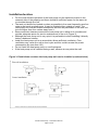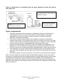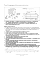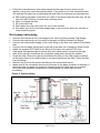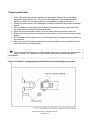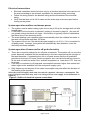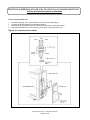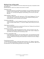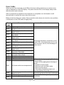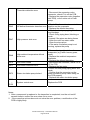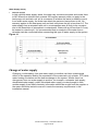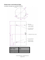
1
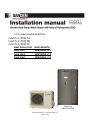
Covering model numbers GAUS-315EQTA GAUS-315EQTB GAUS-315EQTC Heat Pump Unit GAU‐A45HPA Tank Unit HP315SSA_D.2 Tank Unit HP315SSA_C.2 Tank Unit HP315SSA_F.0 Tank Unit GAU‐315EQTA Sanden Heat Pump – Installation Manual Page 1 of 26 Contents Contents .............................................................................................................................................................................. 2 Introduction ...................................................................................................................................................................... 3 How it works ..................................................................................................................................................................... 3 Installation details .......................................................................................................................................................... 4 Installation location ....................................................................................................................................................... 5 Power requirement ........................................................................................................................................................ 6 Piping Connections ........................................................................................................................................................ 7 Heat pump unit piping .................................................................................................................................................. 8 Removing air from the system .................................................................................................................................. 9 Freeze protection ......................................................................................................................................................... 10 Electrical connections ................................................................................................................................................ 11 System operation outline continuous power .................................................................................................. 11 System operation if connected to off‐peak electricity ................................................................................. 11 How to connect tank unit thermistor cable ...................................................................................................... 13 Time setting and block out time setting ............................................................................................................ 14 Blockout time setting mode .................................................................................................................................... 15 Maintenance Mode ...................................................................................................................................................... 16 How to switch to Maintenance Mode .................................................................................................................. 16 Error Codes .................................................................................................................................................................... 17 Change of water supply ............................................................................................................................................. 19 Dimensions and technical data .............................................................................................................................. 20 Warranty Policy ............................................................................................................................................................ 23 Warranty Period .......................................................................................................................................................... 24 Post installation inspection checklist ................................................................................................................. 24 Check sheet ..................................................................................................................................................................... 25 Memo ................................................................................................................................................................................. 26 Warranty ......................................................................................................................................................................... 25 PATENTS This water heater may be protected by one or more patents or registered designs in the name of Sanden Australia Pty Ltd TRADE MARKS ® Registered trademark of Sanden Australia Pty Ltd . Note: Every care has been taken to ensure accuracy in preparation of this publication. No liability can be accepted for any consequences that may arise as a result of its application Sanden Heat Pump – Installation Manual Page 2 of 26 Introduction The Sanden Heat Pump Water Heater System has been designed using the latest refrigeration technology to remove the heat from the air to heat water. The refrigerant we use is CO2 which does not contribute to global warming so it allows us to help keep a clean healthy earth for future generations. We have also considered the power requirement. By using CO2 as the refrigerant we have produced one of the most energy efficient units currently available. It’s even more efficient when connected to off-peak power1 and the noise level is so low it will operate unobtrusively throughout the night. How it works The Heat Pump Water Heater System heats water by transferring the heat from the surrounding air to the water using a refrigerant. The refrigerant is heated by a heat exchanger that absorbs heat from the surrounding air (Figure 1). Figure 1: Heat Pump Water Heater System Heat pump unit Tank unit (hot water storage) Note 1 operating conditions may vary depending on the type of off peak tariff that is available in your area. The unit must have a minimum of 5 hours continuous power available Sanden Heat Pump – Installation Manual Page 3 of 26 Installation details This Heat Pump Water Heater System must be installed by a licensed person in consideration of the following standards and regulations: AS/NZS3500 National plumbing and drainage code hot water supply systems – acceptable solutions HB 263-2004 Heated water systems plumbing industry commission AS/NZS 3000 Electrical installations (known as the Australian/New Zealand wiring rules) Notice to Victorian customers from the Victorian Plumbing Industry Commission. The Victorian Building Act 1993 requires that this Heat Pump Water Heater System must be installed by a licensed person. Only a licensed person will provide a Compliance Certificate, showing that the work complies with all the relevant standards. Only a licensed person will have insurance protecting their workmanship for six years. The unit has been specifically designed for domestic hot water heating and is not suitable for any other purpose. The unit is designed to operate when connected to the town water supply with a maximum operating pressure of 650 kPa. To ensure the mains pressure does not exceed this, a pressure-limiting device that complies with AS1357 must be connected to the town water supply line. This system delivers hot water exceeding 50o C. Reference should be made to AS/NZ3500 and/or local regulations relating to the need for temperature tempering devices. The unit must be stored and transported in an upright position. Failure to do so may render the unit faulty. Such failure is not covered under any warranty agreements. Failure to comply with the above conditions will void the warranty. Figure 2: Typical installation layout Sanden Heat Pump – Installation Manual Page 4 of 26 Installation location For the most efficient operation of the heat pump unit the optimum location is the warmest side of the property and there should be sufficient space for the warm air to circulate through the unit. The tank unit should be located as close as possible to the most frequently used hot water outlet such as a bathroom. It may be located either outside or inside. The heat pump unit must be located outside and as close as practicable to the tank unit but not further than four meters away from it. Ensure sufficient clearance around the heat pump unit to allow air to circulate and provide adequate space for service maintenance of the unit (Figure 3). Although the heat pump unit is very quiet it is preferable to avoid installing it directly below a bedroom window. Install the heat pump unit in an area which allows sufficient ventilation. Poor ventilation may cause the unit to short cycle and this could increase the power consumption by more than 10%. Do not install the heat pump unit in a confined space. If the heat pump unit is installed facing a wall, exhaust air may stain the wall. Figure 3: Restrictions on where the heat pump unit can be installed (overhead view) Flat wall installation Corner installation Sanden Heat Pump – Installation Manual Page 5 of 26 Figure 4: Restrictions on installation with the space between the tank unit and the heat pump unit Overhead view Standard layout Side view Keep the piping run to a minimum as the longer the pipe run the greater the potential for heat loss. Total piping length: 4 metres maximum per way Number of bends: 6 maximum gure 4 (A) Difference in height between the base of tank and base of Heat pump should be no more than: 3m Max. Power requirement The power requirement for the system is a dedicated 17 amp circuit fitted with a circuit breaker. This circuit may be connected to constant power or off-peak. Installation of this system must be carried out only by a qualified installation technician (electrical or plumbing). The surface to which the heat pump unit is installed must be firm, preferably a concrete pad or block. If the surface is firm there is no need to fix the unit to a base surface, unless there is a likelihood of high wind or local vibration. If the heat pump unit and tank unit are fixed, appropriate fixing devices should be used. A pressure and temperature relief (PTR) valve is included in the installation kit of the tank unit. This is installed in a defined point near the top of the tank unit. The PTR valve must have a clear space where escaping steam or water can flow freely. The installation site must be well drained so that any water accumulating (such as local rain or pipe leakage) will drain away and not enter the heat pump unit and the tank unit. Local water pressure must be a minimum of 200 kPa to ensure efficient functioning. Note: The entire system is set up and fully functional when supplied. Once all the water and electric connections have been made the system finds the right timing to run the water heating cycle automatically as long as the electricity is available. The only adjustment required is the current time setting on the timer setting panel under the top housing cover, especially if the blockout time setting is desired. See current time setting and blockout time section on page 14. Sanden Heat Pump – Installation Manual Page 6 of 26 Figure 5: Heat pump installation example and dimensions Attach the drain elbow to the drain opening located on the bottom of the heat pump unit. The drain elbow is included in the installation kit for the heat pump unit. Attach a drain hose with 16mm of inner diameter to the drain elbow to guide the drained water to a appropriate drain Piping Connections All piping that connects to the water supply must be carried out by a licensed plumber. The water supplied to the system must comply with the drinking water quality standard. Use of water that does not comply with this standard could result in a malfunction of the system. The water source must have a pressure of 200 kPa or higher. A drain hopper must be installed under the drain outlet. A drain trap must be installed over the drain pipe if water is to be drained to a drain ditch. If a drain trap is not installed gas could flow out and cause severe corrosion and malfunction of the heat pump unit. This product cannot be connected to a solar water heater. The piping must be appropriately insulated. If the piping needs brazing make sure that all flux and flux splatter is wiped away with a wet cloth. As the hot-water supply pipe will expand and contract use sleeves when passing it through concrete walls or slabs. With buried piping a sheath pipe will need to be used that has had both ends sealed to avoid any rain penetration. Use only heat-resistant and corrosive-resistant material to seal the pipe joints. Cutting and wrenching the piping material may result in oil and dust adhering to it. After processing, clean the material with a mild detergent before doing any piping work and smooth the edges to remove any scratches and burrs. (After passing water through it verify whether any dust has accumulated on the filter of the taps and heat pump unit pipe.) When using sealing tape ensure that no tape is sticking out of the thread. If any heat-resistant vinyl chloride pipes (such as HT pipe) are bonded together, pass water through them after the pipes have set to prevent any bond adhering to the filter or other parts. Sanden Heat Pump – Installation Manual Page 7 of 26 Follow the manufacturer’s instruction manual for the type of bond, amount to be applied, curing time, and other specifications. If any bond or flux has entered the tank unit and the hot water has a chemical/acrid smell take the following countermeasures. a) After heating the water in the tank unit, drain it and clean inside the tank unit. Fill the tank unit with 100 litres of water and exchange twice. b) Clean or change the filter. c) Fill up the tank unit. d) Drain water from the relief valve for one to two minutes. e) Run water from all the hot water supply taps in the house for about ten minutes to clean inside the pipes. Heat pump unit piping Connect the heat pump unit cold supply to the tank unit fitting marked Cold Supply. Connect the heat pump unit hot return to the tank unit fitting marked Hot Return. Connect the mains water supply to the lower fitting on the tank unit marked Cold Water Inlet. Connect the hot water supply pipe to the top of the tank unit marked Hot Water Outlet. Install the supplied PTR valve to the fitting on the tank unit marked PTR valve. Pass water through the pipe to remove any dust inside before connecting the pipe. After all the piping connections are completed, pass water through the system. Close the stop valves (four places) and detach the filter on the cold supply connector of the heat pump unit to confirm there is no object that blocks the filter. Clean the filter if any blockage. Remove the air from the system according to the instructions below. Make sure all the necessary devices are mounted to the pipes as shown in diagram. If the heat pump unit piping is crushed or clogged or the air inside was not removed during the test operation, temperature of the supplied hot water may become inconstant. Figure 6: System piping Sanden Heat Pump – Installation Manual Page 8 of 26 Removing air from the system The following steps must be taken to ensure all air is removed from the system. Incorrect removal of air may cause the water temperature to vary. Plumb pipes to tank unit and heat pump unit. Push up the lever on the PTR valve to open, and fill the tank unit with water. Confirm the water comes out of the relief valve and then close the lever. Open the water tap to remove air. Close the tap after no air is confirmed in the water. Open the water drain plugs (two places) on the heat pump unit. Close the plugs after no air is confirmed in the water. Supply the power to the heat pump unit and leave the water tap open for three minutes. Close the tap after no air is confirmed in the water. Figure 7: Air removing process PTR valve Plumb pipes to Storage Tank Unit and Heat Pump Unit. Push up the lever on the PTR valve to open, and fill in the tank with water. Confirm the water come out of the relief valve, and then close the lever. Water drain plugs Open the water tap to remove air. Close the tap after no air is confirmed in the water. Open the water drain plugs (2 places) on the Heat Pump Unit. Close the plugs after no air is confirmed in the water. Supply the power to the Heat Pump Unit and leave the water tap open for 3 minutes. Close the tap after no air is confirmed in the water. Sanden Heat Pump – Installation Manual Page 9 of 26 Freeze protection Even if the pipes have been insulated, the piping can freeze if the surrounding temperature gets below zero. This could cause damage to the equipment and piping so make sure the appropriate freeze protection measures are taken Follow the instructions in the installation manual provided with the freeze protection heater. After completion of the piping work inspect the plumbing for any water leaks from the joints before carrying out freeze protection. Wrap the freeze protection heater up to the water connectors of the main unit. Ensure the freeze protection heaters are connected to 24 hours continuous power supply.. It is important to fully explain how to use and operate the freeze protection heater to the customer. When turning off the power because the unit will not be in use, any water must be removed from the unit and piping. . Note A heater that checks the outside temperature may not detect the temperature of the piping correctly. It is important to use a heater that directly detects the piping temperature. Figure 8: Details on wrapping thermal insulation around the piping connector Sanden Heat Pump – Installation Manual Page 10 of 26 Electrical connections Electrical installation should be done only by a licensed electrician who carries out the work according to the relevant regulations for electrical safety and wiring. Follow the wiring rules for the breaker rating and the thickness of the electrical wiring. Verify that the tank unit is full of water and the water stop cocks are open before turning on the power. System operation outline continuous power The system runs its water heating cycle once a day to fill up the storage tank unit with heated water. If the block out time function is selected ( setting is covered in page 14 ) the unit will not operate during the block out times – this function is typically used on installations that have time of use electricity tariffs The water heating cycle operation starts automatically when the residual hot water in the tank unit becomes less than 150 litres. The system will not run if the electrical power supply is cut off (i.e. if it is connected to off-peak power). However, the system will automatically start operation, once the electricity becomes available. System operation if connected to offpeak electricity There are no special settings for the off-peak connection. The system will run once the power becomes available and the temperature in the tank drops below the set point of the tank thermister. If connecting the unit to off peak ensure that the off peak tariff provides a minimum of 5 hours continuous power, as it can take at least four hours to fill the tank unit with hot water if the ambient temperature is lower than 10oC this can be longer. If the unit is connected to off peak and consumption has been higher than normal hot water might not be available until the next power supply cycle. Daily frequency and amount of hot water consumption may also affect the duration of the heating cycle operation. Select the electrical supply mode that best suits the customer’s hot water consumption. The type of off-peak connection may need to be changed if hot water supply is not maintained as required. Figure 9: Outline of electrical system connections Sanden Heat Pump – Installation Manual Page 11 of 26 Electrical installation should only be done by a licensed electrician Outline of electrical system connections How to connect power line Remove the piping cover, terminal block cover and screw clamp fitting. Connect the power supply line to the terminal block. Hold the power supply line below the terminal block with the screw clamp fitting. Attach the terminal block cover and piping cover back on the heat pump unit. Figure 10: Connect power cables Sanden Heat Pump – Installation Manual Page 12 of 26 How to connect tank unit thermistor cable Cut the thermistor cable and conduit to the required lengths. The thermistor cable and conduit length are designed to cover the maximum allowable distance between the tank unit and heat pump unit (four meters). If the units are located closer than four meters the thermistor cable and conduit may be cut to the desirable length (Figure 11). Reveal the sheath on the thermistor cable. Attach the conduit connector to the conduit end. Push the conduit into the opening on the connector until the conduit does not go any further. Pull the conduit several times to ensure the connector is fixed properly to the conduit. Unscrew and firmly remove the terminal block cover. Do not use unnecessary force to remove the cover as this could pull and break the cable coming out of the tank unit. Join the connector on the end of the thermistor conduit coming from the heat pump unit side to the opening on the bottom of the cover on the tank unit. Confirm the gasket is attached to the tread of the conduit connector before joining the connector to the cover. If the gasket is not attached, there is a risk of water getting inside the cover and this may result in a malfunction of the terminal block. Connect the thermistor cable to the bottom of the terminal block. Put the terminal block cover back onto the tank unit and tighten the screws. Figure 11: Connect tank unit thermistor cable Tank unit Terminal block Thermister cable Gasket Conduit connecto Conduit Sanden Heat Pump – Installation Manual Page 13 of 26 Time setting and block out time setting Current time setting This product contains a built-in clock IC. As a part of the water heating cycle logic refers to the current time, it is necessary to set the clock before starting to use the product. The current time can be set in the Clock Setting Mode as described below. *Note There is no need to adjust the time setting for the daylight saving period. Even if the installation is conducted during the daylight saving period, the clock setting to the ordinary time (not daylight saving time) is preferable. 1. Switching to Clock Setting Mode Press the “Enter” key in the Clock Display Mode to switch to the Clock Setting Mode. Time Display starts flashing once the mode is switched. 2. Setting the Clock The time setting can be adjusted by pressing “Up” and “Down” keys. Fast forward and rewind are available by pressing and holding down a key. 3. Executing Setting the Clock After the clock is adjusted to the current time, press the Enter key to execute the setting. The time display stops flashing and comes on once the setting is finished. *Caution The display automatically goes back to the Clock Display Mode when no panel operation is performed for more than 60 seconds in the Clock Setting Mode. If this occurs, changes made will not be reflected to the setting. If the clock setting is rewound to a time that is earlier than the time when a heating cycle is triggered, the system will start the heating cycle. *Note When no panel operation is performed for more than 60 seconds the display is switched to the Display Sleep Mode and turns off. Display Sleep Mode is cancelled when Up, Down or Enter key is pressed. Figure 12 Maintenance mode LED Status Window Display Window Enter Button Up/Down Buttons Sanden Heat Pump – Installation Manual Page 14 of 26 Blockout time setting mode This mode is used to set the block out time that blocks the heat pump unit operation within the setting time. Blockout times are used if the customer has a time of use tariff. Change the mode Press and hold down Up and Down keys together in the clock display mode to go to the block out time setting mode. Once the mode is changed, ‘bo’ and ‘00XX’ (00 = start time, XX = end time) are displayed. (Initial setting = 00 o’clock for both start and end) Adjust set block out start time Press Up or Down key and ‘00’ (start time) in ‘00XX’ starts flashing and ‘XX’ (end time) illuminates. Now the block out start time can be adjusted. Setting can be performed only in hour increments, not in minutes. Set block out start time Press the Enter key to set the desired time setting. After the start time is set, the start time display stops flashing. The end time display starts flashing at the same time. Adjust block out end time Set to the desired end time by using Up and Down keys. Setting can be performed only in hour increments, not in minutes. Set block out end time Press enter key to adjust the desired time setting. After the end time is set, the start time and end time are displayed for two seconds, then it starts to display ‘bo’ and ‘00XX’ (00 = start time, XX = end time) by turns. Go back to clock display mode Press Enter key to go back to the clock display mode. It will automatically go back to the clock display mode when no panel operation is performed for more than 60 seconds. Blockout time setting mode cannot be set unless the end time setting is executed. Cancel block out setting To cancel the block out setting, set both start and end times to ‘00’. Setting to other than ‘00’ (01 ~ 23) will be interpreted as a setting error and the end time will flash. Make sure to set both times to ‘00’ when cancelling the block out time setting Sanden Heat Pump – Installation Manual Page 15 of 26 Maintenance Mode Maintenance mode is a function to check the heat pump unit status and to check and perform other settings. It should generally be assumed that the owner does not operate this function. The following modes can be found in the maintenance mode. Blockout time setting mode Set the block out time. Error history display mode Check the history of any errors that may have occurred. Parameter display mode Check the values measured by the thermistor. Drive setting mode: Switch the heat pump unit on/off. Compulsory operation mode: Compulsorily operate the water heating cycle. Pump remote operation mode: Run the water circulation pump. How to switch to Maintenance Mode Press and hold down Up and Down keys together in the clock display mode to go to the maintenance mode. After the mode is switched, press the Enter key to select a mode from the six modes described above. To finish the maintenance mode, press and hold down the Enter key, or leave for more than 60 seconds with no panel operation. Change: Hold down ‘Up’ and ‘Down’; No operation for 60 seconds (delete min.?) – this change needs to be done in three places. Figure 13 Maintenance mode diagram Hold down “UP” and “DOWN” t th Display Sleep Mode Any Key No Operation for 60sec min. Parameter Display Mode Enter Clock Display Mode Enter Enter or No Operation for 60sec min. Clock Setting Mode Blockout Time Setting Mode Enter Error History Display Mode Enter Enter or No Operation for 60sec min. Drive Setting Mode Enter Compulsory Operation Mode Enter Pump Remote Operation Mode Sanden Heat Pump – Installation Manual Page 16 of 26 Enter Error Codes When an error has occurred, a red LED on the timer setting panel turns on and an error code is displayed on the LED display. The panel does not turn to the display sleep mode while the error code is shown. After a component is replaced or the inspection is completed, turn the breaker on/off several times to confirm the error does not re-occur. Below is the list of the error codes. If the corrective action does not solve the error problem, a malfunction of the PCB valve is highly likely. Error code Error contents Corrective action Check the thermistor connectors on the main PCB in the heat pump unit for any disconnection, fall-off, wire breakage or short circuit E020 E021 E040 No error generated HP inlet temperature thermistor wire break HP inlet temperature thermistor short circuit HP outlet temperature thermistor wire break HP outlet temperature thermistor short circuit HP ambient temperature thermistor wire break HP ambient temperature thermistor short circuit HP defrost temperature thermistor wire break HP defrost temperature thermistor short circuit HP discharge temperature thermistor wire break HP discharge temperature thermistor short circuit Tank thermistor a wire break Tank thermistor a short circuit HP water outlet over temperature 1 E041 HP water outlet over temperature 2 E000 E010 E011 E012 E013 E014 E015 E016 E017 E018 E019 E042 E043 E044 HP outlet temperature thermistor detection error HP discharge over temperature 1 Hp discharge temperature - Check the heat pump piping filter for any blockage - Check for any piping bend, blockage or crush - Inspect for frozen pipes - Open the valve on water mains - Open the stop valves - If the water circulation pump is not moving, replace the pump - Check if the thermistor is off the mounting pocket on the water outlet pipe - Replace the discharge temperature thermistor Sanden Heat Pump – Installation Manual Page 17 of 26 Thermistor detection error - Reconnect the expansion valve connector, check if it is off the PCB - Replace the expansion valve (together with PCB), or the entire unit of heat pump - Check if the thermistor is mounted in HP defrost thermistor detection error position on the evaporator - Replace the defrost thermistor - Check the heat pump piping filter for any blockage - Check if any piping bend, blocking or crush - Inspect if the pipes are being frozen High pressure side error - Open the valve on water mains - Open the stop valves - If the water circulation pump is not moving, replace the pump E045 E047 E048 High ambient temperature defrost drive error E070 Fan motor locked E071 Fan motor revolution error E073 Water circulation pump locked E090 ~ E150 System control error - Remove foreign objects from the evaporator (e.g. fallen leaves, grass, snow) - Replace the ambient temperature thermistor - Replace the defrost thermistor - Reconnect the connector, check if it is off the PCB - Replace the fan motor - Check for heat pump piping block and crush - Confirm that the connector on the water circulation pump cable sitting on the PCB properly - Replace the water circulation pump Replace the PCB Notes: 1. After a component is replaced or the inspection is completed, turn the unit on/off several times to confirm the error does not re occur. 2. If the corrective actions above do not solve the error problem, a malfunction of the PCB is highly likely. Sanden Heat Pump – Installation Manual Page 18 of 26 Water Supply Quality Chloride and pH In high chloride water supply areas, the water can corrode some parts and cause them to fail. Where the chloride level exceeds 250 mg/litre warranty does not apply to the heat pump unit and tank unit. pH is a measure of whether the water is alkaline or acid. In an acidic water supply, the water can attack the parts and cause them to fail. No warranty applies to the heat pump unit and tank unit where the pH is less than 6.0. The water supply from a rainwater tank unit in a metropolitan area is likely to be corrosive due to the dissolution of atmospheric contaminants. Water with a pH less than 6.0 may be treated to raise the pH. It is recommended that an analysis of the water from a rainwater tank be conducted before connecting this type of water supply to the system. Figure 14 Change of water supply Changing, or alternating, from one water supply to another can have a detrimental effect on the operation and/or life expectation of the water tank unit cylinder, PTR valve, water heating circulation and the heat exchanger in the system. Where there is a changeover from one water supply to another, for example, a rainwater tank supply, desalinated water supply, public reticulated water supply or water brought in from another supply, then water chemistry information should be sought from the supplier or the water should be tested to ensure it meets the warranty requirements in this installation manual. Sanden Heat Pump – Installation Manual Page 19 of 26 Dimensions and technical data Hot water storage tank unit GAU‐315EQTA Storage capacity Product weight Design pressure Storage tank material Outside casing 315 litres 82 kg 700 kPa Stainless steel Colour coated zinc steel Sanden Heat Pump – Installation Manual Page 20 of 26 Heat pump unit GAU‐A45HPA Refrigerant type Product weight Thermal capacity Power consumption COP Heated water temp. R744(CO2) 56 kg 4.5 kw *1 1.0 kw *1 4.5 *1 65 oC *1 Ambient temp. (Dry / Wet) 16oC / 17oC, Inlet water temps. 17oC, Outlet water temp. 65oC Sanden Heat Pump – Installation Manual Page 21 of 26 Wiring Diagram Sanden Heat Pump – Installation Manual Page 22 of 26 Warranty Policy Warranty Conditions 1. The Sanden Heat Pump Water Heater System must be installed in accordance with the installation instructions supplied with the Heat Pump Water Heater System and in accordance with all relevant statutory and local requirements of the state in which the water heater is installed. 2. Where a failed component or Heat Pump Water Heater System is replaced under warranty, the balance of the original warranty period will remain effective. The replaced part or Heat Pump Water Heater System does not carry a new warranty. 3. Where the Heat Pump Water Heater System is installed outside the boundaries of a metropolitan area as defined by Sanden or further than 25 kilometers from an accredited service agent, the cost of transport, insurance and travelling costs between the nearest accredited service agent's premises and the installed site shall be the owner's responsibility. 4. Where the Heat Pump Water Heater System is installed in a position that does not allow safe, ready access, the cost of accessing the site safely, including the cost of additional materials handling and/or safety equipment, shall be the owner's responsibility. 5. The warranty only applies to the Heat Pump Water Heater System and original or genuine (company) component replacement parts and therefore does not cover any plumbing or electrical parts supplied by the installer and not an integral part of the Heat Pump Water Heater System. Such parts would include pressure limiting valve, isolation valves, non-return valves, electrical switches, pumps or fuses. 6. The Heat Pump Water Heater System must be sized to supply the hot water demand in accordance with the guidelines in the Sanden Heat Pump Water Heater System literature. Warranty Exclusions 1. Repair and replacement work will be carried out as set out in the Sanden Heat Pump Water Heater System warranty. However the following exclusions may void the warranty and may incur a service charge and/or cost of parts: 2. Accidental damage to the Heat Pump Water Heater System or any component, including: Acts of God, failure due to misuse, incorrect installation, attempts to repair the water heater other than by a Sanden accredited service agent or the Sanden service department. 3. Where it is found there is nothing wrong with the Heat Pump Water Heater System; where the complaint is related to excessive discharge from the temperature and/or the pressure relief valve due to high water pressure; where there is no flow of hot water due to faulty plumbing; where water leaks are related to plumbing and not the Heat Pump Water Heater System or its components; where there is a failure of electricity or water supplies; where the supply of electricity or water does not comply with relevant codes or acts. 4. Where the Heat Pump Water Heater System or its component has failed directly or indirectly as a result of excessive water pressure. 5. Overflow vent drain has not been installed or blocked or corroded 6. Where the Heat Pump has rusted as a result of a corrosive atmosphere; 7. Where the unit fails to operate as a result of ice formation in the pipe work to or from the Heat Pump Water Heater System. 8. Where the Heat Pump Water Heater System is located in a position that does not comply with the Heat Pump Water Heater System installation instructions or relevant statutory requirements, causing the need for major dismantling or removal of cupboards, doors or walls, or use of special equipment to bring the Heat Pump Water Heater System to floor or ground level or to a serviceable position. Sanden Heat Pump – Installation Manual Page 23 of 26 9. Repair and/or replacement of the Heat Pump Water Heater System due to scale formation in the waterways or the effects of either corrosive water or water with a high chloride or low pH level when the water heater has been connected to a scaling or corrosive water supply or a water supply with a high chloride or low pH level as outlined in the Owner's Guide and Installation Manual. Subject to any statutory provisions to the contrary, this warranty excludes any and all claims for damage to furniture, carpets, walls, foundations or any other consequential loss either directly or indirectly due to leakage from the Heat Pump Water Heater System, or due to leakage from fittings and/or pipe work of metal, plastic or other materials caused by water temperature, workmanship or other modes of failure. Warranty Period Subject to the Warranty Conditions and Exclusions stated above, your Sanden Heat Pump Water Heater System is warranted as follows: Heat pump unit – Five years from date of installation Tank unit – Ten years from date of installation Post installation inspection checklist On completion of the installation, inspect and check off each item in the charts on the following page once the inspection has been completed remove the inspection table and hand to the customer. Sanden Heat Pump – Installation Manual Page 24 of 26 Check sheet Safety items Action Completed Fix the legs of the tank unit in place with anchor bolts if necessary. The floor has been properly water proofed and properly drained. The earth leakage breaker can be turned off with the test button. Earth (ground) work is implemented. The tank unit is installed on a level sturdy surface. There are no gas containers or flammable materials anywhere near the unit. The wiring between the tank unit and the heat pump unit is properly connected. Around units Action Completed A concrete base block is installed (if necessary). An inspection space is retained in accordance with the installation manual Around the piping Action Completed A dedicated water supply/stop cock is mounted. The metal piping for the water supply/hot water supply pipe has been properly insulated. There is no water leaking from the water supply/hot water supply and heat pump pipes. In areas subject to snap freezes, protection is provided. Union joints are used so that the parts can be easily removed. Piping is installed from the drain outlet and drain hopper to the drain ditch. The filter in the pressure-reducing valve is clean. Independent pipes, not a twin tube, are used for the heat pump unit pipes. The drainage hose from the heat pump unit leads into the drain ditch. Insulation is provided for the water supply/hot water supply and heater pump pipes. During draining of the tank unit water does not overflow from the drain ditch. Installed By…………………………………………………… Date………………………………… Inspected By …………………………………………………. Date………………………………… Sanden Heat Pump – Installation Manual Page 25 of 26 Memo ---------------------------------------------------------------------------------------------------------------------------------------------------------------------------------------------------------------------------------------------------------------------------------------------------------------------------------------------------------------------------------------------------------------------------------------------------------------------------------------------------------------------------------------------------------------------------------------------------------------------------------------------------------------------------------------------------------------------------------------------------------------------------------------------------------------------------------------------------------------------------------------------------------------------------------------------------------------------------------------------------------------------------------------------------------------------------------------------------------------------------------------------------------------------------------------------------------------------------------------------------------------------------------------------------------------------------------------------------------------------------------------------------------------------------------------------------------------------------------------------------------------------------------------------------------------------------------------------------------------------------------------------------------------------------------------------------------------------------------------------------------------------------------------------------------------------------------------------------------------------------------------------------------------------------------------------------------------------------------------------------------------------------------------------------------------------------------------------------------------------------------------------------------------------------------------------------------------------------------------------------------------------------------------------------------------------------------------------------------------------------------------------------------------------------------------------------------------------------------------------------------------------------------------------------------------------------------------------------------------------------------------------------------------------------------------------------------------Sanden Heat Pump – Installation Manual Page 26 of 26 SANDEN Heat Pump 40980‐44090 Installation Manual