1
Important Safety Information
ATTENTION
RISQUE D'ELECTROCUTION !
NE PAS OUVRIR!
CAUTION: TO REDUCE THE RISK OF ELECTRIC SHOCK, DO NOT
REMOVE COVER (OR BACK). NO USER-SERVICEABLE PARTS
INSIDE. REFER SERVICING TO QUALIFIED SERVICE PERSONNEL.
This lightning flash with arrowhead symbol within an equilateral triangle is
intended to alert the user to the presence of non-insulated "dangerous voltage" within the product's enclosure that may be of sufficient magnitude to
constitute a risk of electric shock.
The exclamation point within an equilateral triangle is intended to alert the
user to the presence of important operating and maintenance instructions
in the literature accompanying the appliance.
THIS DEVICE COMPLIES WITH PART 15 OF THE FCC RULES
CLASS B. OPERATION IS SUBJECT TO THE FOLLOWING TWO
CONDITIONS: (1) THIS DEVICE MUST NOT CAUSE HARMFUL
INTERFERENCE, AND (2) THIS DEVICE MUST ACCEPT ANY
INTERFERENCE RECEIVED INCLUDING INTERFERENCE THAT
MAY CAUSE UNDESIRED OPERATION. SUITABLE FOR HOME
OR OFFICE USE.
"'a
A
-
If you want to dispose this product, do not mix it with general household waste. There is a
separate collection system for used electronic products in accordance with legislation that
requires proper treatment, recovery and recycling.
Private household in the 25 member states of the EU, in Switzerland and Norway may return their used
electronic products free of charge to designated collection facilities or to a retailer {if you purchase a similar
new one).
For Countries not mentioned above, please contact your local authorities for a correct method of disposal.
By doing so you will ensure that your disposed product undergoes the necessary treatment, recovery and
recycling and thus prevent potential negative effects on the environment and human health.
Copyright 2013- V2.3
Expedition XP150
SAMSON
Important Safety Information
1.
Read these instructions.
2.
Keep these instructions.
3.
Heed all warnings.
4.
Follow all instructions.
5.
This apparatus shall not be exposed
to dripping or splashing liquid and
no object filled with liquid, such as
a vase, should be placed on the apparatus.
6.
Clean only with a dry cloth.
7.
Do not block any of the ventilation
openings. Install in accordance with
the manufacturer•s instructions.
8.
9.
paratus. When a cart is used, utilize
caution when moving the cart/apparatus combination to avoid injury
from tip-over.
14. Refer all servicing to qualified service
Do not install near any heat sources
such as radiators, heat registers,
stoves, or other apparatuses (including amplifiers) that produce heat.
Only use attachments/accessories
specified by the manufacturer.
10. Unplug this apparatus during lightning storms or when not in use for
long periods of time.
11. Do not override the intended purpose of the polarized or groundingtype plug. A polarized plug has
two blades, with one wider than
the other. A grounding-type plug
has two blades and a third grounding prong. The wide blade, or third
prong, is provided for your safety.
If the provided plug does not fit
your outlet, consult an electrician to
replace the obsolete outlet.
12. Protect the power cord from being
walked on or pinched, particularly at
the prongs, convenience receptacles,
the point where they exit from the
apparatus.
personnel. Servicing is required if the
apparatus has been damaged in any
way, such as power-supply cord or
plug breakage, damage due to liquid
or objects falling onto the apparatus, exposure to rain or moisture, or
if the apparatus does not operate
normally, or has been dropped.
15. POWER ON/OFF SWITCH: For products with a power switch, the power
switch DOES NOT break the connection from the mains.
16. MAINS DISCONNECT: The plug
should remain readily operable.
For rack-mount or installation
where plug is not accessible, an
all-pole mains switch with a contact
separation of at least 3 mm in each
pole shall be incorporated into the
electrical installation of the rack or
building.
17. FOR UNITS EQUIPPED WITH EXTERNALLY ACCESSIBLE FUSE RECEPTACLE: Replace fuse with same type
and rating only.
18. MULTIPLE-INPUT VOLTAGE: This
equipment may require the use of a
different line cord, attachment plug,
or both, depending on the available
power source at installation. Connect
this equipment only to the power
source indicated on the equipment
rear panel. To reduce the risk of fire
or electric shock, refer servicing
to qualified service personnel or
equivalent.
13. Use only with the cart ,
stand, tripod bracket,
or table specified by
the manufacture, or
sold with the apExpedition XP150
3
Table of Contents
Introduction . . . . . . . . . . . . . . . . . . . . . . . . . . . . . . . . . . . . . . . . . . . . . 5
Features . . . . . . . . . . . . . . . . . . . . . . . . . . . . . . . . . . . . . . . . . . . . . . . 6
Setting Up the XP150 . . . . . . . . . . . . . . . . . . . . . . . . . . . . . . . . . . . . . . . 7
XP1 SO Quick Start . . . . . . . . . . . . . . . . . . . . . . . . . . . . . . . . . . -. . . . . . . 9
Configuring the XP1 SO for Transport . . . . . . . . . . . . . . . . . . . . . . . . . . . . 11
XP1 SO Mixer Layout . . . . . . . . . . . . . . . . . . . . . . . . . . . . . . . . . . . . . . . 12
XP1 SO Connections . . . . . . . . . . . . . . . . . . . . . . . . . . . . . . . . . . . . . . . 14
XP1 SO Wiring Guide . . . . . . . . . . . . . . . . . . . . . . . . . . . . . . . . . . . . . . . 15
Specifications . . . . . . . . . . . . . . . . . . . . . . . . . . . . . . . . . . . . . . . . . . . 16
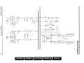
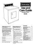
Block Diagram . . . . . . . . . . . . . . . . . . . . . . . . . . . . . . . . . . . . . . . . . . 17
4
Expedition XP150
SAMSON
Introduction
Thank you for purchasing the Expedition XP150 Portable PA System from Samson!
The XP150 features a compact, 5-channel mixer with 150 watts of on board power and
dual 2-way speakers, making it an ideal solution for a variety of small- to medium-size d
PA applications. The XP150 is also extremely portable, thanks to its lightweight and
unique "Slide and Lock" design.
The 5-channel mixer can be removed from the speaker for tabletop use. It features
three inputs for connecting microphones , plus one channel for connecting a stereo
signal from an MP3 player, or other electronic device. There's also a built-in digital effects processor to add reverb to your voice or instrument. The mixer provides a robust
output, with 150 watts total power from the lightweight, Class D amplifier section.
The XP150 employs a matched speaker system with dual 2-way enclosures that have
proprietary 6-inch woofers and 1-inch high frequency drivers. To help project sound
to a larger audience, the XP150 speakers can be mounted on standard speaker stands,
thanks to the integral pole mount receptacles. The XP150 is constructed using durable
ABS high impact plastic, making it super road tough and, at the same time, lightweight.
In this manual, you'll find a detailed description of the features of the XP150 PA system,
as well as a description of its front and rear panels, step-by-step instructions for its
setup and use, and full specifications. You'll also find a warranty card enclosed-pl ease
don't forget to fill it out and mail it in so that you can receive online technical support,
and so we can send you updated information about these and other Samson products
in the future. Also, be sure to check out our website (www.samso ntech.com) for complete information about our full product line.
With proper care and adequate air circulation, your XP150 will operate trouble free
for many years. We recommend you record your serial number in the space provided
below for future reference.
Serial number:._ _ _ _ _ _ _ _ _ _ _ __
Date of purchase:._ _ _ _ _ _ _ _ _ _ __
Should your unit ever require servicing, a Return Authorization (RA) number must
be obtained before shipping your unit to Samson. Without this number, the unit will
not be accepted. Please call Samson at 1-800-3SAMSON (1-800-372-6766) for an RA
number prior to shipping your unit. Please retain the original packing materials and, if
possible, return the unit in the original carton and packing materials. If you purchased
your Samson product outside the United States, please contact your local distributor
for warranty information and service.
Owner's Manual
Expedition XP150
5
Features
•
The XP150 is a compact PA system with dual 2-way speakers, on board mixer, and
150 watt power amplifier.
•
The XP150 is the ultimate in portability . The lightweigh t, clever design allows you
to slide and lock the two speakers together to carry all componen ts together in a
single, easy to move case. The mixer is stored in one of the speaker cabinets. The
second cabinet has a compartm ent for storing the speaker cables, microphon es,
and other accessories.
•
The speakers are 2-way vented enclosures with 6-inch woofers. Each is complimented by a l-inch high frequency driver, and set in a custom horn with a 60 x 90
degree coverage pattern producing a clean, clear sound.
•
The XP1 SO speaker cabinets feature a tilt back monitor position for use without
speaker stands or as a performan ce monitor.
•
The internal2 x 75 watt lightweigh t Class D power amplifier produces a powerful
stereo sound.
•
The XP1 SO's mixer can be removed from the speaker for tabletop use.
•
The 5-channel mixer features three Mic/Line inputs allowing you to connect microphones or line signals. In addition, one stereo input channel allows you to connect
line level signals from keyboards, drum machines and MP3 or CD players. The mixer
provides+ 1SV of phantom power to use with condenser microphon es.
•
On each of the mixer's channel inputs there is a Bass and Treble control allowing
you to equalize the tone of the individual inputs.
•
To create a lush sound on any of the microphon e channels, you can use the internal
effects processor to add Digital Reverb.
6
Expedition XP1 50
SAAISD N
Setting Up the XP150
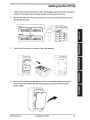
1.
Unpack all the system components from the shipping carton and save all packing
materials in the event your unit ever needs to be returned for service.
2.
Remove the mixer by turning the quarter turn screw counterclockwise towards
the RELEASE position.
LOCK
®
111111 m~Wf.111111111
RELEASE
®
®
~
~0 ~~· 0
111111 ifil~ 111111111
®
o:
~o~~ oEi}
~o~~ o(O
~ ~~ 00
0
3.
Carefully hold the mixer to remove it from the speaker.
4.
Remove the accessory compartment cover by turning the quarter turn screw
counterclockwise towards the RELEASE position, and remove the included
speaker cables.
Owner's Manual
Expedition XP150
7
Setting Up the XP150
5.
Replace the accessory panel by aligning the bottom of the panel with the slots.
Make sure the quarter turn screw is in the RELEASE position; then close the panel
and turn the quarter turn screw clockwise to LOCK.
6.
Position the speakers on the floor or on stands.
7.
Using one of the included speaker cables,
connect the mixer's LEFT SPEAKER OUT to the
left speaker's input connector. Next, use the
second included speaker cable to connect
the RIGHT SPEAKER OUT to the right speaker's
input connector.
8
Expedition XP150
SAMSON
XP150 Quick Start
1.
Be sure that the XP150's POWER switch is set to the OFF position.
2.
If the speakers are not connected, connect the speaker wires as described in the
previous section.
3.
Turn each of the channel volume (VOL) and MASTER volume controls fully counterclockwise, to the "0" position.
4.
Next, connect one side of the included power cable to the XP150 mixer's power
inlet and the other to a grounded AC power outlet.
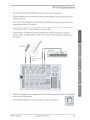
5.
Connect your microphones using standard XLR cables, instruments using W'
phone cables, and MP3 player using 3.Smm cable, into the appropriate jacks on
the mixer.
Electric Acoustic
Guitar
6.
Switch on all equipment connected to the XP150, then switch the XP150's POWER
switch to the ON position.
7.
Turn the MASTER level control up halfway, to the "5" position.
MASTER
Owner's Manual
Expedition XP150
9
XP150 Quick Start
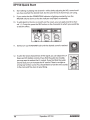
8.
Start talking or playing into channel1 while slowly adjusting the VOL control until
you have reached the desired level. Do the same for each channel you are using.
9.
If you notice that the POWER/PEAK indicator is lighting constantly, turn the
MASTER volume down so that the indicator only lights occasionally.
10. To add depth to the mix or smooth out the vocals, you can apply reverb to channel 1-3. To do this, press the REV button on the channel(s) to which you would like
to add the effect.
11. Slowly turn up the REVERB knob until the desired sound is reached.
12. To alter the tonal characteristic of the signal, you can adjust the LF
(bass) and HF (treble) controls. If you find the audio too muddy,
you may want to reduce the LF control. If you find that the audio
sounds dull, you can increase the HF control. There is no right or
wrong way to EQ a sound. You should listen to how the mix sounds
in the room and fine-tune to your liking.
10
Expedition XP150
51JWI50N
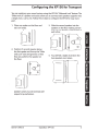
Configuring the XP150 for Transport
You can easily carry your sound system using the XP150's 1/Siide and Lock" feature. The
liS Iide and Lock" speaker enclosures allow you to connect both speakers together into
a single, easy to carry unit. Follow these steps to configure the XP150 for easy transport.
1. Place one speaker on the floor and
· set it on its side.
2. Position the second speaker above
the first speaker and line up the "Slide
and Lock" tracks and grooves so that
they are parallel to the speaker on
the floor.
3. Slide the second speaker into the
speaker on the floor making certain
that the two speakers stay parallel to
each other.
4. You will feel a slight click when the
two speakers are in place.
Speaker cabinets must be reversed with
respect to top and bottom.
Owner's Manual
Expedition XP150
11
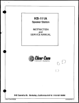
XP1 SO Mixer Layout
®
----
®
1
®
CH'1
®
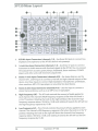
1.
XLR Mic Input Connectors (channels 1-3)- Use these XLR jacks to connect low
impedance microphones to the XP150's built-in mic preamps.
2.
%-inch Line Input Connectors (channels 1-3)- Use these 1.4" jacks to connect
instrument or audio sources with line level signals to the XP150. You can connect
the outputs from acoustic guitar pickups, keyboards, drum machines, CD/MP3
players and other units with line level outputs here.
3.
Stereo %-inch Input Connectors (channels 4/5) - For stereo devices, use the
channel4/5 Land R inputs to connect to the left and right channel outputs of the
device. Use these inputs to connect high impedance microphones, synthesizers,
drum machines, MP3, CD, tape players or any other line level device.
4.
Stereo 3.5mm Input Connector (channels 4/5)- Use this input to connect a
stereo line level device, such as an an MP3, CD, or tape player.
5.
High Frequency (HF) -The HF knob controls the amount of treble applied to
each channel. The channel's HIGH frequency response is flat when the knob is
in the "0" position. Rotating the knob to the right will boost the channel's high
frequency response above 10 kHz by 15 dB, and rotating it towards the left will cut
the high frequency response by 15 dB.
6.
Low Frequency (LF) -The LF knob controls the amount of bass applied to each
channel. The channel's LOW frequency response is flat when the knob is in the "0"
position. Rotating the knob to the right will boost the channel's low frequency
response below 100Hz by 15 dB, and rotating it towards the left will cut the low
frequency response by 15 dB.
12
Expedition XP150
SAMSON
XP150 Mixer Layout
7.
REVERB Switch- Use the REVERB switch to add an effect to a Mic or Line input on
any of the inputs 1-3. The REVERB LED indicator lights GREEN when the REVERB is
ON.
8.
REVERB Indicator-The REVERB LED will illuminate when the REVERB switch is
pressed down, indicating the channel is set to add reverb (see #7 above).
9.
VOLUME Control Knob- This knob sets the overall level for each channel's Mic or
Line input. NOTE: To reduce noise, set the VOLUME controls on any unused channels to the minimum setting.
10. SPEAKER OUT Jacks- The XP150 has two Y4-inch phone connectors, which are
powered outputs used to connect your left and right speakers. Use the included
speaker cables to connect the speakers.
CAUTION: The total impedance load for each side of the amplifier must not be less
than 8 Ohms. Do not connect additional speakers to the XP150 mixer.
11. SPEECH/MUSIC Switch- The SPEECH/MUSIC switch is used to change the overall
frequency response, or tone contour, for the XP150 sound system. If your application is mainly for music, press the switch down to select the MUSIC response
curve. If your application is mainly for speech, leave the switch up to select the
SPEECH response curve.
12. REVERB Control Knob- The REVERB control knob is used to adjust the total
amount of reverb added to all channels with their REVERB switch (see #7 above)
pressed down.
13. MASTER Volume Knob- The MASTER volume knob controls the overall output
level. Signals from all five channels are routed here just before being routed to the
built-in power amplifiers and Left and Right output jacks (see #1 0 above).
14. POWER Switch- Use the POWER switch to turn power to the XP150 on or off.
15. Power/Peak Indicator- This LED will illuminate GREEN when the MAIN power
switch is turned on, and light RED when the when the amp is near the clipping
point. If the Peak indicator lights frequently, turn down the MASTER volume control or turn down the input channel VOL controls, until the indicator does not light
anymore, or lights only occasionally with signal peaks.
16. IEC Inlet- Connect the supplied heavy-gauge 3-pin 1EC" power cable here.
11
17. Mixer Lock- Turn this quarter turn lock counterclockwise, to the RELEASE poisition, to remove the mixer from the rear of the speaker cabinet. When transporting
the XP150, make sure the lock is in the LOCK position.
Owner's Manual
Expedition XP150
13
.,....><
....
~
-------
U1
0
~ -----1
f ~ ~ IRimiWimiRIIIWIIIWIIIRI!I
c=::J o II
~--~
®
X
""0
m
a.
c=;:
6'
::::l
-u
~
U1
0
®
----- 0 0 0
-
m
X
----
a:------
HF
D
1DK
~11,
HF
10K
D
aQX"'"".-e
aQX"'"".-s
~~~
+-11!1
,.,a_
~~~
+.. ,.,
,,l'-
'IOtffi\10 'IOtffi\_10
o
HF
10K
a.f..~X"'"".-a\ 10
'IDC>
..
~
1
ul1-
· +lJ1e
HF
o
10K
A
.-.MUSIC
_o
1o_ tffi\.
~~~
D
18°-
1----
. -.. "
LF
LF
IU
I
I
I
®
VDL
t
® f.~0;1(''..,...,\
;I(..,..._
~;
\
f.
\
0-
CH 1
[!JJ !
8PIIIICH
sQX"t..,..._.a
\o•-
.. 10
CH2
CH3
CH 4115
;
"·u:~
MASTER
1
I
,..tDn
-·::s
0
"'
...
UN&
UN&
LINE
-1-
&~ciJ
n
0
::s
::s
~·
~
Ul
·l£~·~··- • ii()
-
.z
ol::::
Dei. C)
a• ·•aw..·
.li·
~··--•-·· ·-·xw
-'"•
®
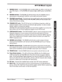
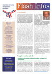
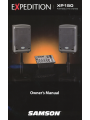
This example shows a typical PA system for a cocktail band using the XP 750 with two microphones, acoustic guitar, and keyboards, and
an MP3 player connected for background music.
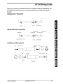
XP150 Wiring Guide
There are several ways to interface the XP150 to support a variety of applications. The
XP150 features balanced inputs, so connecting balanced and unbalanced signals is
possible.
Unbalanced Y4" Connector
Tip (signal)
Signal
Sleeve (ground)
Ground
Ground
Stereo TRS 3.5mm Connector
Tip (left signal)
Right Signal (ring)
Ring (rig~t signal)
Left Signal (tip)
Left Signal (tip)
~
t
I II:)
Right Signal (ring)
Ground
Sleeve (ground)
Ground
XLR Balanced Wiring Guide
+Hot
Common (1) +Hot (2)
Common (ground)
W..__'----4C~_.__I___]___J(gr~und)y
t
I
-lnlrl
-{nlrl
+Hot (2)
End View Solder Points ~
®
(2)
Owner's Manual
;(grourn-d)-----~..
@
f~i
\
+Hot
~
1~~----t
I
i
I
- Cold (3)
SoQts
Common (ground)
Common (1)
r-
End View
-Cold
Male XLR
Expedition XP150
15
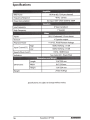
Specifications
,
Amplil1e1 ·
150 W@ 80 (75 W per channel)
RMS Power
Frequency Response
40Hz-20kHz
Power Consumption
AC Input 100V--240V 50/60Hz 180W
Low Frequency
6" bass transducer
High Frequency
1"tweeter
XLR, ~"balanced, 3.5 mm stereo
Inputs
114" Speaker output
Outputs
+ 15V DC, Fixed Phantom Voltage
Phantom Power
Input Channel EQ
High
1OkHz Shelving ±15 dB
Low
100Hz Shelving ±15 dB
Speech/Music Switch
Two Color LED- Power/Peak
Indicators
Dimensions
150Hz, 18dB/Octave
Length
15.6"/395 mm
Width
8.6"/218 mm
Height
13.9"/354 mm
24 Ibs/1 0.8 kgs
Weight
Specifications are subject to change without notice.
16
Expedition XP150
51JAf50N
~
m
0:::
:J
CD
...,_
LrJ
>
LrJ
..JO:O:::
en
s:
Q)
:J
c:
Q)
-I
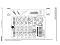
-32dBu
I
+ +
Inputs
CH1-3
~
I
HIGH
LOW
II
OdBu
-
LEVEL
REVERB.
I
I
"'0
CD
a.
a:
0
:JI
n ~ BA/
X
-o
~I
I
EQ
I
I
~w ~GH
++
Inputs
CH4/5
I
I
OdBu
I LEVEL
I
. . .
.
~
.
~
L
~-
.
-~
-0n
ta
~
c
-·
AI
\Q
IIIII
AI
3
~I
ITALIANO
ESPANOL
DEUTSCHE
FRAN~AIS
ENGLISH