1
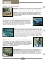
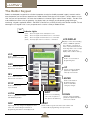
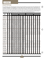
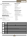
Series 15H Applications
Centrifugal Fan – The Baldor inverter is used to adjust the CFM (and associated pressure) of
a fan. Typically, in the past, inlet vanes and outlet dampers have controlled air flow. These
techniques are effective and well accepted, but not very energy efficient. With the Baldor
inverter – vanes, dampers,actuators and their associated maintenance may be eliminated.
Additionally and most importantly, power consumption is decreased by the cube of the
speed decrease. This means a potential for tremendous energy savings. Simple control of
speed through the process follower input allows “closed loop” control of your air flow.
We have also included 3 skip frequencies to avoid those “critical speed bands” that might
cause excessive vibration.
Conveyor – Baldor’s inverter is the perfect solution to control the speed of a conveyor.
Inverters are used for different products run on one conveyor, various processes, different
shifts, etc. Control of speed can be with a potentiometer, a process follower or simple
switch closures (with up to 15 preset speeds)! Built into the control is dynamic braking to
allow the operator to “ramp down” the conveyor speed instead of just coasting down.
Also, the control will allow full torque at low speeds through our built in auto torque boost.
We have also included an “s-curve” for an easy start and landing during acceleration and
deceleration. A great help to keep productivity up, and reduce scrap.
Pump – In Baldor’s tradition of being a value supplier of energy efficient motors – Baldor’s
inverter includes several different “square reduced” volts/hertz curves. This allows the
drive to operate close to the pumps output requirements - an absolute energy saver for
variable flow applications. With the Baldor inverter, throttling valves can be eliminated and
flow controlled from adjustable motor speed. With the adjustable acceleration time (up to
3600 seconds), water hammer can be significantly reduced if not entirely eliminated. The
mechanical stresses in your pump and motor will also be greatly reduced. Additionally,
inrush current associated with across-the-line starts can be dramatically reduced. Once
again, simple control through the keypad, potentiometer, or process follower (0 - 10VDC,
0 - 5VDC or 4-20 mA) input is available.
Photo courtesy of Goulds Pumps
Mixer – Baldor’s Series 15H inverter includes many features that make it ideal for mixing
applications. We include the ability to control speeds through a process follower, the keypad
or switch closures for various speeds. Included is a minimum speed so the operator cannot
turn the speed down below a set value, to keep the mixture from “setting up”. Adjustable
current limit will trip off the drive at a set torque (related to viscosity) level. High speeds for very
fluid materials (up to 7200 rpm or more) are possible! You can even read current on the
keypad and use it as a determination of viscosity.
Packaging Equipment – (Typically constant torque applications) – Baldor’s Series 15H
inverter provides wide constant torque speed ranges with its superior torque boost and the
potential for changing base speed beyond 60 hertz for applied motors. The process
following feature allows a master controller to control the entire process. Also, the analog
output can be tied into the analog input of another control for leader/follower applications.
2
Matched Performance™
33.0
11.00
30.0
10.00
TORQUE (ft-lbs)
PEAK TORQUE
27.0
9.00
24.0
8.00
AMPS
21.0
7.00
18.0
6.00
15.0
HP
TORQUE
5.00
12.0
4.00
9.0
3.00
CONTINUOUS
OPERATING AREA
6.0
2.00
3.0
1.00
HORSEPOWER • AMPS
ID15H405-E Control
IDM3665T Motor 5HP
RATED
0.0
0
400
800
1200
1600
2000
2400
2800
3200
3600
0.00
SPEED (rpm)
Matched Performance™ is Baldor’s solution to the concern, “what kind of constant torque and constant
horsepower speed range will I get with this inverter”? And, “what happens if I use a fan cooled motor, an open
drip proof motor or a blower cooled motor, etc.”? Baldor has gone beyond the (2:1, 6:1, 10:1) ratio type
answers and has documented actual laboratory dynamometer testing.
At the heart of these tests is the continuous operating constant torque range. This range of values show how
much torque can be continuously generated without exceeding a Class F temperature rise. This holds true even
with the Class H insulated inverter and vector motors.
The horsepower curve is simply the horsepower representation of the constant torque test.
Peak torque is the maximum amount of torque the Series 15H inverter and the specified motor can produce.
The limit may be breakdown torque of the motor or it may be the control’s current limit. This torque can be used
for momentary overloads and/or for acceleration/deceleration.
Each test is performed by Baldor’s own testing laboratory using state-of-the-art dynamometers, thermocouples
and digital power measuring equipment. A typical matched performance test requires 2 - 4 days of continuous
testing. This painstaking effort is another example of Baldor’s commitment to the drives business and to making
our products easy to use.
3
The Baldor Keypad
Baldor has developed a keypad which will allow the operator to enjoy the flexibility expected in today’s controls and the
ease of operation you have always hoped to have. Baldor includes twelve keys on the keypad. The keys depress so you
“feel” that you have pushed them. We have also included a 32 character English “alpha-numeric” display. You don’t have
to be a detective to know what you are doing - the display helps you whether you are operating, programming or
monitoring. Keypads supplied on NEMA 1 and NEMA 4 controls carry a NEMA 4X rating when remote mounted. The real
advantage in this keypad is that it’s easy to operate and is used on a variety of Baldor controls.
JOG
Indicator Lights
(JOG) –
(FWD) –
(REV) –
(STOP) –
Green Lamp lights when JOG Speed is active.
Green Lamp lights when FWD direction is commanded.
Green Lamp lights when REV direction is commanded.
Red Lamp lights when motor STOP is commanded.
LCD DISPLAY
Displays control status including
LOCAL or REMOTE operation,
motor direction command, set
value of each parameter/function,
monitoring values such as output
frequency and current, also
displays fault conditions and log.
JOG
Used to call up
preprogrammed JOG speed.
PROG
Used to access the block
programming area.
FWD
Used to initiate a forward
direction run of the motor.
UP
Used to change the display
parameter or parameter
value up one increment.
REV
Used to initiate a reverse
direction run of the motor.
ENTER
Used to take the block
programming menu
down one level while
saving any changes.
STOP
Used to initiate a motor
stop command.
LOCAL
Used to toggle between LOCAL
and REMOTE operation.
SHIFT
Used to move the blinking
cursor over one space for
each push of the SHIFT key.
DOWN
Used to change the display
parameter or parameter value
down one increment.
DISP
RESET
Depressing this key changes the displayed control
status. Also used to bring the lower block
programming menu back to the display mode.
Used to initiate a logical reset after a fault condition and
to take the block programming menu up one level.
4
Series 15H Features
FWD
MOTOR SPEED
LOCAL
1750 RPM
Removable Keypad
The Baldor keypad is designed to be removed from the main control and
mounted up to 100 feet away. This will allow the control to be mounted in
a convenient location, and the keypad near the operator for ease of use.
COMMAND
SELECT
P:
POTENTIOMETER
English Display
The keypad displays both the operating conditions and the programming
steps in easy to follow English. This eliminates the need to look up
parameter numbers, program the wrong setting and all the other “easy”
mistakes when working with codes.
ENTER
PRESS ENTER FOR
PRESET
SPEEDS
Single Function
Each key has one function.There is not a whole set of “second operations”
that each key can perform confusing the operator.
Block Programming
It is easy to adjust the control. Most controls force the operator to scroll
through every parameter to get to the one desired. With block
programming, the adjustments are in blocks of like adjustments. For
example, if you wanted to adjust a preset speed, you would find the block
that says: Press ENTER for preset speeds. If you didn’t want a preset
speed your arrow keys take you to the next block of adjustments.
ENTER FOR
Input Terminals
The terminal connections allow control of the drive from a potentiometer
(power provided), a set point controller (PID) through analog input or a PLC
(or switch closures) for discrete preset speeds.
PRESS ENTER FOR
OUTPUT
Output Terminals
The control provides two programmable analog (0 - 5VDC) outputs.
These outputs can be used to run meters or as an input to other controls
for “leader/follower” applications. The control also provides two optically
isolated discrete outputs along with two Form C relay outputs. The opto’s
are powered by a 5 - 30VDC power supply, and the relays are capable of
switching up to 230VAC. The outputs are programmable for settings such
as Ready, At Speed, Zero Speed, Reverse, Fault, etc.
PRESS
INPUT
JOG
FWD
LED’S On Action Keys
There is one LED on each of the following: JOG, FWD, REV and STOP.
These LED’s are “ON” whenever the COMMAND is active. When you
command FORWARD - the LED in the FWD key comes on (STOP and
REV are off). These LED’S are still active when you are controlling from
the terminal strip, plc, switch closures, etc. The active LED lets the
operator know the command has been received and accepted (no broken
wires or dirty contacts).
5
Quad Ratings
Why Quad Ratings? With Quad Rating each control can be setup to operate in one of four distinct output operating zones.
The zones are defined by the PWM frequency, continuous output current, and peak output current. The control may also
have different horsepower ratings depending on the selected operating zone. By selecting the desired Operating Zone the
control will automatically set the PWM frequency, continuous current, and peak current to the proper values for the desired
operating zone. The available Operating Zones are Standard PWM Constant Torque, Standard PWM Variable Torque, Quiet
PWM Constant Torque, and Quiet PWM Variable Torque. No need to worry about derating/rerating the control based on
manufacturers equations or derating curves, Quad Ratings will take care of the derating/rerating for you.
CATALOG
NO.
ID15H201-E, -W
ID15H202-E, -W
ID15H203-E, -W
ID15H205-E, -W
ID15H207-E, -W
ID15H210-E, -W
ID15H215-E, -W
ID15H220-E
ID15H225-EO
ID15H230-EO
ID15H240-EO
ID15H250-EO
ID15H401-E, -W
ID15H402-E, -W
ID15H403-E, -W
ID15H405-E, -W
ID15H407-E, -W
ID15H410-E, -W
ID15H415-E, -W
ID15H420-E, -W
ID15H425-E
ID15H430-EO
ID15H440-EO
ID15H450-EO
ID15H460-EO
ID15H475-EO
ID15H4100-EO
ID15H4150V-EO
ID15H4150-EO
ID15H4200-EO
ID15H4250-EO
ID15H4300-EO
ID15H4350-EO
ID15H4400-EO
ID15H4450-EO
ID15H4500-EO
ID15H4600-EO
ID15H4700-EO
ID15H4800-EO
ID15H501-E, -W
ID15H502-E, -W
ID15H503-E, -W
ID15H505-E, -W
ID15H507-E, -W
ID15H510-E, -W
ID15H515-E, -W
ID15H520-E
ID15H525-E
ID15H530-EO
ID15H540-EO
ID15H550-EO
ID15H560-EO
ID15H575-EO
ID15H5100-EO
ID15H5150V-EO
ID18H5150-EO
ID15H5200-EO
ID15H5300-EO
ID15H5350-EO
ID15H5400-EO
INPUT
VOLT SIZE
230
230
230
230
230
230
230
230
230
230
230
230
460
460
460
460
460
460
460
460
460
460
460
460
460
460
460
460
460
460
460
460
460
460
460
460
460
460
460
575
575
575
575
575
575
575
575
575
575
575
575
575
575
575
575
575
575
575
575
575
A
A
A
A
B2
B2
B2
B2
C2
C2
D2
D2
A
A
A
A
A
B2
B2
B2
B2
C2
C2
D2
D2
D2
E
E
F
F
F
G2
G2
G2
G
G+
G+
G+
G+
A
A
A
A
A
B2
B2
B2
B2
C2
C2
D2
D2
E
E
E
F
F
G
G
G
STANDARD 2.5 kHz PWM
CONSTANT TORQUE
VARIABLE TORQUE
QUIET 8.0 kHz PWM
CONSTANT TORQUE
VARIABLE TORQUE
HP
KW
IC
IP
HP
KW
IC
IP
HP
KW
IC
IP
HP
KW
IC
IP
1
2
3
5
7.5
10
15
20
25
30
40
50
1
2
3
5
7.5
10
15
20
25
30
40
50
60
75
100
150
150
200
250
300
350
400
450
500
600
700
800
1
2
3
5
7.5
10
15
20
25
30
40
50
60
75
100
150
150
200
300
350
400
0.75
1.5
2.2
3.7
5.5
7.4
11.1
14.9
18.6
22.3
29.8
37.2
0.75
1.5
2.2
3.7
5.5
7.4
11.1
14.9
18.6
22.3
29.8
37.2
44.7
56
75
112
112
149
187
224
261
298
336
373
447
522
597
0.75
1.5
2.2
3.7
5.5
7.4
11.1
14.9
18.6
22.3
29.8
37.2
44.7
56
75
112
112
149
224
261
298
4.0
7.0
10
16
22
28
42
54
68
80
105
130
2.0
4.0
5.0
8.0
11
14
21
27
34
40
55
65
80
100
125
180
190
250
310
370
420
480
540
590
710
830
950
1.5
3.0
4.0
7.0
9.0
11
17
22
27
32
41
52
62
77
100
145
150
200
290
340
390
8.0
14
20
32
44
56
84
108
116
140
200
225
4.0
8.0
10
16
22
28
42
54
68
70
100
115
140
200
220
300
380
500
620
630
720
820
920
1180
1210
1660
1710
3.0
6.0
8.0
14
18
22
34
44
54
56
75
92
109
155
200
260
300
400
580
680
780
2
3
5
7.5
10
15
15
25
30
30
50
50
2
3
5
7.5
10
15
20
25
25
40
40
60
75
100
125
150
200
250
300
350
400
450
500
600
700
800
900
2.0
3
5
7.5
10
15
20
20
25
40
50
60
60
100
125
150
200
250
350
400
450
1.5
2.2
3.7
5.5
7.4
11.1
11.1
18.6
22.3
22.4
37.2
37.2
1.5
2.2
3.7
5.5
7.4
11.1
14.9
18.6
18.6
29.8
29.9
44.8
56
75
93
112
149
186.5
224
261
298
336
373
447
522
597
671
1.5
2.2
3.7
5.5
7.4
11.1
14.9
14.9
18.6
29.8
37.2
44.7
44.7
75
93
112
149
186
261
298
336
7
10
16
22
28
42
54
54
80
80
130
130
4.0
5.0
8.0
11
14
21
27
34
34
52
52
80
100
125
160
180
240
310
370
420
480
540
590
710
830
950
1070
3.0
4.0
7.0
9.0
11
17
22
22
27
41
52
62
62
100
125
145
200
250
340
390
440
8
12
19
25
32
48
62
62
92
92
150
150
5.0
6.0
10
13
17
24
31
39
39
60
60
92
115
144
184
207
276
360
430
490
560
620
680
820
960
1100
1230
4.0
5.0
8.0
11
13
20
25
25
31
47
60
71
71
115
145
166
230
290
400
450
510
0.75
1
2
3
5
7.5
10
15
20
25
30
40
0.75
1
2
3
5
7.5
10
15
15
25
30
40
50
60
75
100
125
150
200
0.75
1
2
3
5
7.5
10
10
20
25
30
40
50
-
0.56
0.75
1.5
2.2
3.7
5.5
7.4
11.1
14.9
18.6
22.3
29.8
0.56
0.75
1.5
2.2
3.7
5.5
7.4
11.1
11.1
18.6
22.3
29.8
37.2
44.7
56
75
93
112
149
0.56
0.75
1.5
2.2
3.7
5.5
7.4
7.4
14.9
18.6
22.3
29.8
37.2
-
3.0
4.0
7.0
10
16
22
28
42
54
70
80
105
1.5
2.0
4.0
5.0
8.0
11
14
21
21
35
40
55
65
80
100
125
150
190
250
1.1
1.5
3.0
4.0
7.0
9
11
11
22
27
32
41
52
-
6.0
8.0
14
20
32
44
56
84
92
122
160
183
3.0
4.0
8.0
10
16
22
28
42
42
61
80
92
122
160
183
240
260
380
500
2.2
3.0
6.0
8.0
14
18
22
22
44
47
58
73
91
-
1
2
3
5
7.5
10
15
20
25
30
40
50
1
2
3
5
7.5
10
15
20
20
30
30
50
60
75
100
125
150
175
250
1
2
3
5
7.5
10
10
10
25
30
40
50
60
-
0.75
1.5
2.2
3.7
5.5
7.4
11.1
14.9
18.6
22.3
29.8
37.2
0.75
1.5
2.2
3.7
5.5
7.4
11.1
14.9
14.9
22.3
22.3
37.2
44.7
56
75
93
112
131
187
0.75
1.5
2.2
3.7
5.5
7.4
7.4
7.4
18.6
22.3
29.8
37.2
44.7
-
3.6
6.8
9.6
16
22
28
42
54
68
80
104
130
2.0
4.0
5.0
8.0
11
14
21
27
27
40
40
65
80
100
125
160
170
210
310
1.5
3.0
4.0
7.0
9
11
11
11
27
32
41
52
62
-
4.2
7.8
11
19
25
32
48
62
78
92
120
150
3.0
5.0
6.0
10
13
16
24
31
31
46
46
75
92
115
144
184
200
240
360
1.7
4.0
5.0
8.0
11
13
13
13
31
37
47
60
71
-
NOTE: -E is NEMA 1 enclosure with built-in dynamic braking; -W is NEMA 4X enclosure with built-in dynamic braking; -EO is NEMA 1 enclosure requires external braking kit
6
DESIGN SPECIFICATIONS
OPERATOR KEYPAD
•
•
•
•
•
•
•
•
•
•
•
•
•
•
•
•
•
•
•
•
•
•
•
•
•
•
•
•
Microprocessor controlled PWM output
Output frequency 0.25-120Hz, optional 0.25-400Hz
Peak overload capacity of 200%
Process follower 0-5VDC, 0-10VDC, 4-20mA
Free run or ramp stop
Controlled reversing
Selectable preset speeds
Jog speed
Dynamic braking
DC Injection braking
Separate accel/decel rates
PID-Setpoint control
Bus present and fault trip LED
Fault trip output for customer use
2 Programmable analog meter outputs
4 Programmable Opto outputs
NEMA 1 enclosure as standard (-E, -EO) 1-800 hp
NEMA 4X enclosure as standard(-W) 1-20 hp
ENVIRONMENTAL AND
OPERATING CONDITIONS
• Input voltage - 1 or 3 phase 200-240
VAC±10%, 3 phase 380-480 VAC ±10%, 3 phase 550-600
VAC ± 10%
• Input frequency - 50 or 60Hz ±5%
• Service factor - 1.0
• Duty - continuous
• Humidity - 90% max RH non-condensing
• Altitude - 3300 feet max without derate
Output
Ratings
Overload
Capacity
Frequency
Voltage
Input
Frequency
Ratings
Voltage
Phase
Control
Impedance
Spec
Method
Speed Setting
Accel/Decel
Dynamic Braking
LCD
Setup
Display
Running
Faults
Diagnostics
Ambient
Temperature
Conditions Cooling
Altitude
Humidity
Digital speed control
Forward command
Reverse command
Stop command
Jog speed
Display 32 character alpha-numeric
Local/Remote key
Remote mount to 100 feet
Membrane keys with tactile feel
NEMA 4X enclosure
PROTECTIVE FEATURES
• Selectable automatic restart at
momentary power loss with free
setting of maximum number of trips
and time between trip and reset
• DC bus charge indicator
• Adjustable time-base overload
• Cause of last 31 trips retained in memory
• Linear heat sink thermal sensor
• Digital display for fault conditions including:
- Over voltage
- Under voltage
- Over current
- Ground fault
- Drive overload
- Heatsink thermal
- External trip
150% for 60 seconds, 170-200% for 3 seconds constant torque
115% for 60 seconds for variable torque
0-400Hz
0-Maximum Input Voltage (RMS)
50 Hz
60 Hz
180-230 VAC
340-457 VAC
180-264 VAC
340-528 VAC
495-660 VAC
Three Phase or Single Phase with derate
1% minimum for required for sizes B2, C2, D2, F, G, G2, G+; 3% minimum for sizes A, E
Sinewave Carrier Input, PWM Output
±5vdc, 0-5vdc, ±10vdc, 0-10vdc, 4-20mA, Digital via Keypad, RS-232, RS-485, DeviceNet, Modbus Plus, Profibus
0-3600 Seconds linear or S-curve to maximum speed
20% Min on E,W models, EO models require optional external assemblies
Parameter values for setup and review
Motor RPM, output current, output voltage, local remote control, Fwd/Rev
Separate message for each trip, last 31 retained in memory
Review of setup and operating parameters
0-40 Deg C for UL listing
Forced air included when required
0-3300 feet without derate
0-90% Max RH non-condensing for NEMA 1; 100% condensing for NEMA 4
7
Typical Remote Control Connections
Operation Mode: Standard run - 3 wire control
J4
1
ANALOG GND
2
ANALOG INPUT #1
3
POT REFERENCE
4
ANALOG INPUT+ #2
5
ANALOG INPUT - #2
PROGRAMMABLE 0-5V OUTPUT (FACTORY SETTING: SPEED)
6
ANALOG OUT 1
PROGRAMMABLE 0-5V OUTPUT (FACTORY SETTING: CURRENT)
ENABLE
7
ANALOG OUT 2
8
INPUT #1
9
INPUT #2
10
INPUT #3
11
INPUT #4
12
INPUT #5
13
INPUT #6
14
INPUT #7
15
INPUT #8
16
INPUT #9
17
39
+24VDC
18
40
OPTO IN POWER
19
41
OPTO OUT #1 RETURN
COMMAND POT 5K
0-5VDC OR
0-10VDC OR
4-20 mA
FORWARD RUN
REVERSE RUN
STOP
CLOSED=JOG SPEED
ACC/DEC/"S" SELECT
CLOSED=PRESET SPEED #1
FAULT RESET
MOTOR TEMP SWITCH
Opto In Common
Opto Out Common
USER COMMON
USER +5-30VDC
Opto Out #1
EXTERNAL
POWER
SUPPLY
Opto Out #2
20
42
OPTO OUT #2 RETURN
Relay Out #1
21
43
RELAY OUT #1 RETURN
Relay Out #2
22
44
RELAY OUT #2 RETURN
RELAY COILS
Keypad Extension Cable
For the convenience of our
customers, we offer a connected
plug/cable assembly. This
assembly provides the connectors
from the keypad to the control for
remote keypad operation.
CATALOG
NO.
CABLE EXTENSION
LENGTH
APPROX
SHPG. WGT.
CBLH015KP
5 FEET (1.5 METER)
2
CBLH030KP
10 FEET (3.0 METER)
4
CBLH046KP
15 FEET (4.6 METER)
6
CBLH061KP
20 FEET (6.1 METER)
8
CBLH091KP
30 FEET (9.1 METER)
12
CBLH152KP
50 FEET (15.2 METER)
18
CBLH229KP
75 FEET (22.9 METER)
26
CBLH305KP
100 FEET (30.5 METER)
30
8
Dynamic Braking Resistor Assemblies (RGA)
Dynamic Braking Resistor Assemblies include braking resistors completely assembled and mounted into a NEMA 1 enclosure. For 25 hp
and above (-EO Controls), select the braking resistor from the table with the matching ohms for the RTA selected and adequate
continuous watts capacity to meet load requirements. For 1 to 20 hp (-E Controls) select the braking resistor that has correct ohm value
for the control and adequate continuous watts capacity to meet load requirements.
INPUT
VOLTS
230
460
575
HP
TOTAL
OHMS
1-2
3-5
7.5-10
15-20
25-40
50
1-3
5-7.5
10
15-25
30-60
75-250
300-450
1-2
3-5
7.5-10
15
20-30
40-150
30
20
10
6
4
2
120
60
30
20
10
4
2
200
120
60
30
24
14
600
1200
RGA630
RGA620
RGA1230
RGA1220
RGA1210
RGA1206
RGA1204
RGA6120
RGA660
RGA630
RGA620
RGA12120
RGA1260
RGA1230
RGA1220
RGA1210
RGA1204
RGA6200
RGA6120
RGA660
RGA630
RGA12200
RGA12120
RGA1260
RGA1230
RGA1224
CONTINUOUS RATED WATTS
2400
4800
6400
RGA2430
RGA2420
RGA2410
RGA2406
RGA2404
RGA2402
RGA24120
RGA2460
RGA2430
RGA2420
RGA2410
RGA2404
RGA2402
RGA24200
RGA24120
RGA2460
RGA2430
RGA2424
RGA2414
9600
14200
RGA4820
RGA4810
RGA4806
RGA4804
RGA4802
RGA6402
RGA9602
RGA14202
RGA4860
RGA4830
RGA4820
RGA4810
RGA4804
RGA4802
RGA6404
RGA6402
RGA9604
RGA9602
RGA14204
RGA14202
RGA4860
RGA4830
RGA4824
RGA4814
RGA6414
RGA9614
RGA14214
Dynamic Braking Transistor Assemblies (RTA)
Dynamic Braking Transistor Assemblies include braking transistor completely assembled and mounted into a NEMA 1 enclosure, to be
used with External Dynamic Braking Resistor Assemblies (RGA). Select RGA assembly with matching minimum OHMS and continuous
regenerative power (Watts) capacity to meet load requirements. For use with -EO Controls.
HP
20
25
30
40
50
60
75
100
150V
150
200
250
300
350
400
450
Min. Ohms
CAT. NO.
150%
125%
100%
75%
62%
–
–
–
–
–
–
–
–
–
–
–
6
RTA2-6
208-230 VAC
150%
150%
150%
115%
92%
–
–
–
–
–
–
–
–
–
–
–
4
RTA2-4
MAXIMUM BRAKING TORQUE IN % OF MOTOR RATING
380-480 VAC
150%
150%
150%
150%
150%
150%
150%
150%
150%
120%
150%
150%
150%
90%
150%
150%
150%
72%
150%
150%
–
60%
150%
150%
–
48%
96%
150%
–
36%
72%
150%
–
28%
56%
150%
–
–
48%
126%
–
–
36%
95%
–
–
29%
76%
–
–
–
62%
–
–
–
54%
–
–
–
47%
–
–
–
41%
2
20
10
4
RTA2-2
RTA4-20
RTA4-10
RTA4-4
150%
150%
150%
150%
150%
150%
150%
150%
150%
150%
150%
150%
125%
108%
94%
84%
2
RTA4-2
150%
150%
150%
127%
100%
85%
68%
50%
40%
34%
25%
–
–
–
–
–
24
RTA5-24
550-600 VAC
150%
150%
150%
150%
150%
145%
116%
87%
70%
58%
44%
35%
29%
–
–
–
14
RTA5-14
150%
150%
150%
150%
150%
150%
150%
150%
150%
150%
150%
122%
100%
87%
76%
68%
4
RTA5-4
Dynamic Braking Assemblies (RBA)
INPUT VOLTAGE
Dynamic Braking Assemblies include braking transistor and braking resistors completely assembled and mounted into a NEMA 1
enclosure. Select braking assembly from table with adequate maximum braking torque(%) and continuous regenerative power(Watts)
capacity to meet load requirements. For use with -EO controls.
HP
200
to
240
380
to
480
550
To
600
20
90%
150%
150%
150%
150%
150%
150%
150%
150%
25
75%
125%
150%
150%
150%
150%
150%
150%
150%
MAXIMUM BRAKING TORQUE IN % OF MOTOR RATING
30
40
50
60
75
100
150V
60%
45%
36%
100%
75%
62%
150%
115%
92%
120%
90%
72%
60%
48%
36%
28%
120%
90%
72%
60%
48%
36%
28%
150%
150%
150%
120%
96%
72%
56%
120%
90%
72%
60%
48%
36%
28%
120%
90%
72%
60%
48%
36%
28%
150%
150%
150%
120%
96%
72%
56%
9
150
48%
-
200
36%
-
250
29%
-
CONT.
WATTS
600
1800
4000
600
1800
4000
600
1800
4000
CATALOG
NO.
RBA2-610
RBA2-1806
RBA2-4004
RBA4-620
RBA4-1820
RBA4-4010
RBA5-624
RBA5-1824
RBA5-4014
Expansion and Accessory Boards
Baldor offers a wide variety of plug-in expansion boards to allow the Series 15H vector
controls to be interfaced with various inputs and outputs. One or two expansion boards may
be mounted into the control to custom tailor the inputs, outputs, and feedback requirements
to the application. Baldor also offers several expansion boards that will allow direct interfacing
with popular PLC’s.
Group 1 Boards
Isolated Input Board - EXB003A04 (10-30 Volts)
Isolated Input Board - EXB003A05 (90-130 Volts)
This board replaces the opto inputs on the main control board with isolated inputs. All inputs
must be in the same voltage range and one side of all inputs is common. Screw terminals are
provided for easy connection.
Master Pulse Reference/Pulse Follower - EXB005A01
This board is jumper selectable to create a master pulse reference based on the controls
speed/direction command or selected as an isolated pulse follower. The follower can be
ratioed up or down to the master pulse through the control keypad. The master or follower
pulse train can also be configured as a two channel quadrature pulse with complements or
configured as a one channel pulse train for speed and one channel for direction. As a follower,
the pulse train will be retransmitted to the next follower as received from the master.
DC Tach Interface - EXB006A01
Allows a DC Tachometer to be used as a feedback or command signal to the controls built-in PID Set Point Controller. Jumper selectable for 7,
10, 15, 20, 30, 50, 60, 100, 200, 250 VDC per 1000 RPM tachometers with a software trim for 10% tolerance. Screw terminals are provide for
easy connection.
Group 2 Boards
RS232/RS485 Serial Communication - EXB012A01
Allows serial communication for commands and monitoring. 115.2K baud maximum transmission rate. Screw terminals are provided for easy
connection.
Four Output Relay/3-15 PSI Pneumatic Interface - EXB004A01
Converts 3-15 PSI air pressure to 0-10 VDC or 10-0 VDC (inverted) to be used as a command or feedback signal. Also includes four output
relays to replace the four opto outputs on the main control board. Two relays are jumper selectable for N.O. or N.C., rated for 230 VAC , 5 Amps
max and two form “C” relays (N.O. and N.C.). Please note that relay outputs are dry contacts with no power supplied from the control. Screw
terminals are provided for relay connections and air hose connects to 1/8" O.D. nipple on expansion board.
High Resolution Analog Board - EXB007A02
Contains one high resolution input channel to replace Analog Input #2 on the main control board. The resolution will be as follows: ±10 VDC = 16
bit, 0-10 VDC = 15 bit, ±5 VDC = 15 bit, 0-5 VDC = 14 bit, 4-20 mA = 15 bit. Also contains two high resolution analog outputs to replace Analog
Output #1 and #2 on the main control board. The outputs are selectable for ±10 VDC, 0-10 VDC, and 4-20 mA with inverting capability. Requires
100 second warm up period for full 16 bit resolution. 12 bit minnimum. Screw terminals are provided for easy connection.
Two Analog Output/ Three Relay Output Board - EXB010A01
Provides two isolated analog outputs each with 0-5 VDC, 0-10 VDC, or 4-20 mA capability. Also includes three relay outputs jumper selectable
for N.O. or N.C. rated for 230 VAC, 5 amps maximum. Uses screw terminals for connection.
DeviceNet Communication Board - EXB013A01
Allows connection to DeviceNet communications bus. Uses plug in terminals for connection.
Profibus DP Communication Board - EXB014A01
Allows connection to Profibus DP communications bus. Uses plug in terminals for connection.
Modbus Plus Communication Board - EXB015A01
Allows connection to Modbus Plus communications bus. Uses plug in terminals for connection.
Group 1 and Group 2 Ordering/Mounting Information
• NOTE: Expansion boards plug into the main control board inside the control. When using one expansion board, either a Group 1 or Group 2
board will connect to the main control board. When two expansions boards are used, one must be from Group 1 and one from Group 2. The
Group 1 board will connect to the main control board and the Group 2 board will connect to a stacking connector on the Group 1 board.
Accessory Boards
Isolated Input/2 Relay Output Accessory Board - ACB003A01
Contains 9 isolated inputs for 90-130 VAC. Also has 2 Relay outputs, Form C: N.O. and N.C. Accessory board mounts in expansion board slot
but uses wiring harness to connect to motor control card.
10
Outline and Dimensions
Z
U
JOG
Ø.25
LOCAL PROG
FW
D
DISP
REV
SHIFT ENTER
STOP
RESET
X
Y
V
.25
DIMENSIONS-IN (mm)
OUTSIDE
MOUNTING
HEIGHT(X) WIDTH(V) DEPTH(Z) HEIGHT(Y) WIDTH(U)
12.272
7.974
7.120
11.5
7.2
(312)
(203)
(181)
(292)
(183)
12.150
8.700
8.730
11.5
7.2
(309)
(221)
(222)
(292)
(183)
SIZE
A
B2
Z
U
AIR
OUTLET
JOG
Y
LOCAL
FWD
DISP
REV
SHIFT
STOP
RESET
PROG
ENTER
X
V
SIZE
NOTE: Size B2, C2, D2, E and F
controls can also be mounted in
a thru wall configuration. Please
contact Baldor for thru wall
mounting dimensions.
C2
D2
E
F
G
G2
G+
11
DIMENSIONS-IN (mm)
OUTSIDE
MOUNTING
HEIGHT(X) WIDTH(V) DEPTH(Z) HEIGHT(Y) WIDTH(U)
16.98
10.5
9.66
15.58
7.76
(431)
(267)
(245)
(396)
(197)
24.0
13.0
10.33
23.0
9.5
(610)
(330)
(262)
(584)
(241)
30.0
17.7
12.0
29.0
14.25
(762)
(450)
(305)
(737)
(362)
45.0
27.0
13.0
44.0
22.75
(1143)
(686)
(330)
(1118)
(578)
93.0
31.5
23.6
FLOOR MOUNT
(2362)
(800)
(600)
65.98
31.6
23.49
FLOOR MOUNT
(1676)
(803)
(597)
93.7
63
23.6
FLOOR MOUNT
(2380)
(1600)
(600)
Baldor offers a broad line of products to meet your application
needs. Visit www.baldor.com to request copies of these catalogs:
Series 18H
Vector Controls
BR718
Inverter and Vector
Drive Motors
BR400
Stock
Product
Catalog
Large Frame
AC Induction Motors
BR435
5
0
1
Effective: March 12, 2001
Generators
Inverters &
Vectors
General
Purpose
TM
Premium
Efficiency
Made in the U.S.A.
Commercial
Duty
Washdown Duty
Motors and Drives
Washdown
Motors &
Controls
Large Frame AC
Washdown Duty
Motors and Drives
BR455
Made in the U.S.A.
Direct Current Motors
and Drives 1/50 - 600 Hp
Stock Products
501
Three Phase Line
and Load Reactors
BR1301
© Baldor Electric Company
BR715
www.baldor.com
Grinders
DC Motors
& Controls
DC Motors and
Drives 1/50-600 Hp
BR600
Super-E Premium
Efficient Motors
BR457
Baldor Electric Company
P. O. Box 2400
Fort Smith, AR 72902-2400 U.S.A.
Ph (501) 646-4711 • Fax (501) 648-5792
International Fax (501) 648-5895
www.baldor.com
Printed in U.S.A.
2/01 PROG 25,000