1
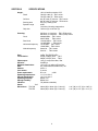
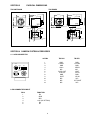
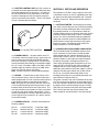
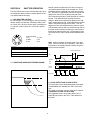
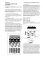
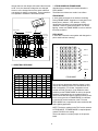
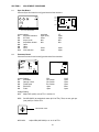
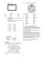
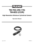
TM-7CN / TM-6CN
TM-7EX / TM-6EX
TM-72EX/TM-62EX
Miniature CCD Cameras
Operations Manual
rev. 05/02
PLEASE NOTE:
The specifications and instructions in this manual apply to the TM-72EX/TM-62EX, with the following exceptions.
Imager size: 2/3” interline transfer CCD
Pixels:
TM-72EX (EIA): 768 (H) x 493 (V)
TM-62EX (CCIR): 758 (H) x 581 (V)
Cell size:
TM-72EX (EIA): 11µm x 13µm
TM-62EX (CCIR): 11µm x 11µm
TV resolution:
TM-72EX (EIA): 570 (H) x 485 (V) lines
TM-62EX (CCIR): 560 (H) x 575 (V) lines
TABLE OF CONTENTS
Page
1.
Features and Applications
............................................................................................... 2
2.
Specifications
3.
Physical Dimensions
4.
Camera System Accessories
.........................................................................................
4.1
12-Pin Connector
...............................................................................................
4.2
Shutter Control Unit
............................................................................................
4.3
Power Cables
....................................................................................................
4.4
Lenses
...................................................................................................................
4.5
Power Supplies
...................................................................................................
4
4
5
5
5
5
5.
Setup and Operation
.........................................................................................................
5.1
Getting Started
......................................................................................................
5.2
Power Supply and Power Cable Setup
..................................................................
5.3
Attaching the Video Output
..................................................................................
5.4
Lenses
.....................................................................................................................
5.5
Shutter Control Setup
...........................................................................................
5
5
5
6
6
6
6.
Shutter Operation
............................................................................................................
6.1
BCD Shutter Control
............................................................................................
6.2
Substrate Drain Shutter Mechanism
.....................................................................
6.3
Sync Output and Clock Output
............................................................................
7
7
7
7
7.
CCD Characteristics and Operation
..............................................................................
7.1
Theory of Operation
............................................................................................
7.2
Mechanism of CCD Charge Transfer
..................................................................
7.3
Spectral Response
.............................................................................................
7.4
Field Mode and Frame Mode
..............................................................................
8
8
8
9
9
8.
Timing Charts
9.
Adjustment Procedure
9.1
Sync Gen Board
9.2
Processor Board
9.3
Imager Board
.................................................................................................
...............................................................................................
...............................................................................................
..................................................................................................
11
11
11
12
10.
External Sync Version For TM-7EX/TM-6EX Only
........................................................
10.1
External Sync Specification
.................................................................................
10.2
Pin Configurations
..............................................................................................
10.3
Asynchronous Reset
............................................................................................
10.4
Phase Adjustment
...............................................................................................
12
12
12
12
13
11.
Connector Board
11.1
Impedance Selection
11.2
Jumper Setting
..................................................................................................................... 3
........................................................................................................ 4
.................................................................................................................... 10
........................................................................................................... 13
............................................................................................ 13
.................................................................................................. 13
3
SECTION 1
FEATURES AND APPLICATIONS
PRECISE IMAGE GEOMETRY
On the CCD image sensor, the photosensor elements
form exact rows both horizontally and vertically so that
a very precise image geometry may be obtained.
HIGH RESOLUTION, INTERLINE TRANSFER CCD
The TM-7/TM-6 series are state-of-the-art CCD cameras which use a 1/2 inch high resolution imager.
These units offer outstanding compactness, high performance, long life, high stability as well as a number of
technical innovations such as variable electronic shutter and asynchronous reset. They are designed to be
simple yet high quality cameras for versatile applications such as machine vision and image processing,
robotics, medical, and surveillance applications. The
uniqueness of the TM-7 series is the size and resolution which is essential for the latest artificial intelligence. For applications requiring external sync, the
TM-7EX is used.
LOW LAG/HIGH RESISTANCE TO IMAGE BURNING
Compared to the lag of conventional cameras which
use a pickup tube, the lag of a CCD camera is considerably reduced so that a clear picture may be obtained
when shooting a rapid moving object, or when shooting
in a low illumination environment. Since the CCD is
highly resistant to image burning, the camera may be
exposed to bright objects for a long period of time. It
must be noted that a “smear” phenomenon may occur
when shooting a very bright object. An infrared cutoff filter is recommended to obtain a clear picture.
VARIABLE ELECTRONIC SHUTTER AND RANDOM
CCD INTEGRATION
The TM-7 / TM-6 series cameras have a substrate
drain-type shutter mechanism which provides a superb
picture at various speeds without smearing. The "CN"
and "EX" model cameras have the capability to externally vary the electronic shutter rate via a manually
controlled BCD switch from 1/60 to 1/10,000 sec. in
discrete steps.
HIGH RESISTANCE TO MAGNETIC FIELD AND
VIBRATION/MECHANICAL SHOCK
Due to its ruggedized design, the CCD imager can
withstand strong vibration and shock, and little or no
noise will appear in the picture. Since the TM-7 series
camera is not influenced by a magnetic field, it will produce stable images even when placed next to objects
such as electric furnaces, welding machines, or NMR
scanners.
MINIATURIZED AND LIGHTWEIGHT
All PULNiX cameras are built with the same design principles: solid state technology; miniaturization (including
lenses, housings, and cables); specialization (such as
remote imager and image intensified camera versions).
The use of a CCD image sensor in the video camera
module and the development of special mini C-mount
lenses makes it possible to produce a very compact,
lightweight, and robust series of cameras. The TM-7
series is the extension of this principle and makes the
entire camera just like a remoted head.
QUICK START-UP AND LOW POWER CONSUMPTION
No more than 2 seconds are needed for the TM-7
series to warm up, and shooting may begin within a
second after turning on the camera. The power consumption is only 3.0W. This makes the cameras excellent for use with battery operated systems.
GENLOCK CIRCUIT
A genlock circuit is not built into the TM-7 series to
accept external sync. The design principle of this type
of camera is intended for numerous usages in simple
but demanding applications which require compact,
high resolution and high quality, but most importantly,
low cost cameras. External sync is built into the TM7EX series for applications where external sync is
required.
LONG LIFE: A THREE YEAR WARRANTY
The CCD solid state image sensor allows the camera
to maintain a superior performance level indefinitely
while requiring virtually no maintenance. PULNiX
backs all of the TM series cameras with a three year
warranty.
WARNING: Unscrewing the camera cover or opening the
camera in any way will void this warranty.
AGC SELECTION, MANUAL GAIN CONTROL AND
GAMMA ADJUSTMENT
The AGC (automatic gain control) may be externally
switched from automatic to fixed gain on the TM-7CN
back plate. The manual gain is externally adjustable.
Gamma may also be externally set either to 1 or 0.45.
These adjustments are particularly important in vision
system applications.
HIGH SENSITIVITY
The TM-7 series is one of the most low light sensitive
1/2 " CCD cameras available today. This is especially
important when using the faster shutter speeds. The
CCD detects images into the near infrared. It requires
only 1.0 lux of minimum illumination and 0.5 lux minimum illumination at maximum gain. In general, such a
low light camera allows use of a higher lens F-value
and provides greater depth of field and sharper
images.
4
SECTION 2
SPECIFICATIONS
Imager:
Pixels
Cell size
Sensing area
Dynamic range
Chip size
Scanning:
Clock
Pixel clock
Horizontal frequency
Vertical frequency
Sync:
TV resolution:
Video output:
S/N ratio:
Minimum illumination:
AGC:
Gamma:
Lens mount:
Power requirement:
Operating temperature:
Storage temperature:
Operating humidity:
Storage humidity:
Vibration:
Shock:
70G
Dimensions: TM-7CN
TM-7EX
1/2 inch interline transfer CCD
768 (H) x 494 (V) - TM-7 series
752 (H) x 582 (V) - TM-6 series
8.4 (H) x 9.8 (V) microns - TM-7 series
8.6 (H) x 8.3 (V) microns - TM-6 series
6.41 (H) x 4.89 (V) mm
67dB
Low noise, blooming suppression
7.95 mm (H) x 6.45 mm (V)
525 lines, 2:1 interlace - TM-7 (EIA) series
625 lines, 2:1 interlace - TM-6 (CCIR) series
28.6363 MHz - TM-7 series
28.375 MHz - TM-6 series
14.31818 MHz - TM-7 series
14.1875 MHz - TM-6 series
15.734 KHz - TM-7 series
15.625 KHz - TM-6 series
59.92 Hz - TM-7 series
50.0 Hz - TM-6 series
Int/Ext TM-7EX/TM-6EX
570(H) x 485(V) lines - TM-7
560(H) x 575(V) lines - TM-6
1.0V p-p composite video, 75Ω
50 dB min.
1.0 lux (F=1.4) without IR cut filter
On (16dB standard, 32dB max) / Off
0.45 or 1
C-mount
DC 12V,
2.5 W
-10 °C to +50 °C
-30 °C to +60 °C
Within 70%
Within 90%
7G (200Hz to 2000Hz)
46mm (W) x 40mm (H) x 74mm (L)
46mm (W) x 40mm (H) x 79mm (L)
5
1.81" (W) x 1.57" (H) x 2.95" (L)
1.81" (W) x 1.57" (H) x 3.11" (L)
SECTION 3
PHYSICAL DIMENSIONS
TM-7CN/TM-6CN
TM-7EX/6EX
73.9 mm
45.8 mm
78.9 mm
45.8 mm
61.3 mm
66.3 mm
PULNiX
PULNiX
39.4 mm
39.4 mm
TM-7 EX
TM-7 CN
7.0 mm
7.0 mm
2X 11.0 mm
2X 11.0 mm
1/4-20 UNC-2B
1/4-20 UNC-2B
2x M6x1
2x M3x1
30.4 mm
30.4 mm
SECTION 4 CAMERA SYSTEM ACCESSORIES
4.1 12-PIN CONNECTOR
12-PIN #
LENS
AGC
GAIN
VIDEO
VISION
SYSTEM
1
2
3
4
5
6
7
8
9
10
11
12
6-PIN CONNECTOR PINOUT
PIN #
1
2
3
4
5
6
FUNCTION
D2
GND
IRIS
+12V (5V OPTION)
D0
D1
6
TM-7CN
TM-7EX
GND
+12VDC
GND
Video
N/C
SYNC OUT
CLK OUT
GND
VINIT
N/C
N/C
N/C
GND
+12V DC
GND
VIDEO
N/C
VINIT
VD IN
GND
HD IN
N/C
INT CONT
N/C
4.2 SHUTTER CONTROL UNIT (SC-745)- consists of
a manually controlled 8-position BCD switch that determines the exposure time of the sensor. It connects to
the TM-7CN/TM-7EX via a cable with a PC-6P male
connector that plugs into the 6-pin female connector
socket on the back of the camera. The SC-745 shutter
control is included with the camera.
SECTION 5 SETUP AND OPERATION
The operation of the TM-7 series requires a lens (mini
or standard C-mount), a 12V DC regulated power supply, power and video cable assemblies and, if needed,
a shutter control unit. Setup of the camera system is
as follows:
5.1 GETTING STARTED - Please begin by checking
your order to assure that you have received everything
as ordered, and that nothing has been overlooked in
the packing materials. It is a good idea to retain the
original packing cartons for cameras and lenses should
there be a need at a later date to return or exchange
an item. It is also recommended that any equipment
being sent to another location for field installation be
bench tested to assure that everything is fully operational as a system. The following steps outline the
setup procedure for PULNiX cameras.
5.2 POWER SUPPLY AND POWER CABLE SETUP
The TM-7CN/6CN and TM-7EX/6EX cameras use a
12-pin connector for power input. Consult the data
sheet packed with your camera. Generally Pin #1 is
Ground and Pin #2 is +12V DC. The other pins may
handle a number of other input and output functions;
this will be discussed in subsequent sections. For
users simply providing power through the 12-pin connector, the DC-12P and PD-12P power supplies are
available with the 12-pin mating connector already
attached to the leads from the power supply. For those
using the PULNiX power cables such as the 12P-02,
KC-10, etc., be certain that unused leads are not
touching and that there is no possibility that leads can
short because of exposed wire (s).
The power connector may now be attached to the camera. The 12-pin power connector is keyed and will only
fit in one orientation. Rotate the connector while applying slight pressure until the keyways line up. You may
now press the connector into place until firmly seated.
The 110V AC line cord may now be placed in the
mains recepticle, and the camera is now powered up.
SC-745 SHUTTER CONTROL
4.3 POWER CABLES - all power cables use a PC12P female connector that fits into the 12-pin male connector on the back of the TM-7CN/TM-7EX camera.
Due to the connector's miniature size, PULNiX recommends purchasing the following pre-assembled cables:
KC-10 10 feet, 4 conductor cable (12V, GND); 12POX
Variable length, 8 conductor cable (12V, GND, Video,
Clock out, Sync out, Async Vinit input l)
Note: Consult PULNiX for custom cable assemblies.
4.4 LENSES - PULNiX offers a wide variety of 2/3
inch format mini lenses. Auto-iris lenses must have a
cable equipped with a PC-6P connector mating into the
6-pin female connector on the back of the camera.
Note: Normally, the TM-7CN and TM-7EX series cannot do variable shuttering while using an auto-iris lens
because these functions share one 6-pin socket. The
user has to build his own interface in order to use both
an auto-iris lens and a shutter control switch. This is
done by separating the +12VDC, GND and video wires
(for the auto-iris lens), and the D0, D1, and D2 controls
(for the BCD switch).
4.5 POWER SUPPLIES - PULNiX recommends the
following supplies:
K25-12
P-15-12
K50-12
PD-12P
110V AC/12V DC,
220V AC/12V DC,
110V AC/12V DC,
110V AC/12V DC,
2.1A power supply
2.1A power supply
4.2A power supply
0.5A power supply
7
5.3 ATTACHING THE VIDEO OUTPUT
Most users utilize the BNC connector on the "CN" and
"EX" versions for video output from the camera.
Connect the output from the camera to the input of
your monitor, VCR, or switching device. The input of
the monitor should be balanced for 75Ω termination.
Standard RG-59 type coaxial cable should carry a full
video signal for up to 500 feet.
5.4.2 AUTO-IRIS LENS SETUP
Power down the camera before attaching auto-iris
lens. Mount the auto-iris lens following the instructions
above. Plug the connector provided on the lens into
the connector on the rear of the camera marked
AUTO-IRIS or simply LENS. You may now power up
the camera. Point camera at a light area and then
quickly towards a darker area. If everything is working
properly, the iris should adjust for the light change.
5.4 LENSES
C-mount lenses are attached to the camera by carefully engaging the threads and rotating the lens
clockwise until it firmly seats on the mounting ring. Do
not force the lens if it does not seat properly. Some
lenses with extremely long flangebacks may exceed
the mounting depth of the camera. The TM-7 series
cameras use 1/2" format lenses.
NOTE: There is a small chance that damage could
occur to the auto-iris lens by plugging or unplugging
the lens into the LENS connector on the camera while
the camera is still powered up. It is a good idea to
always remove power from the camera before connecting or disconnecting the lens.
5.5 SHUTTER CONTROL SETUP
The SC-745 Shutter Controller is used to externally
vary the shutter speed of the TM-7CN/6CN and TM7EX/6EX. This controller plugs into the 6-pin connector on the rear of the camera normally used for autoiris lenses. Switching the controller will obtain the
desired shutter speed. See the key to controller
speeds on the associated data sheet for the camera
being shuttered. The SC-745 must remain attached to
the camera to use the shutter feature of the camera
unless the camera is specially modified to shutter
internally. If at a single speed it is desired to use an
auto-iris lens and SC-745 at the same time, a special
6-pin connector must be made up which breaks out
the SC-745 and lens connections as separate outputs.
See Section 6 for pin-outs and speed menu.
5.4.1 BACK FOCUSING LENSES
To backfocus the TM-7CN, TM-7EX cameras, first
attach a C-mount lens in the mount. Be certain that the
lens is properly seated. Next set the lens focus to infinity (and if the lens is a manual iris, set the iris to a high f
number while still retaining a well illuminated image).
Try to obtain the best focus at this setting. Then loosen
the two miniature hex head set screws locking the
focus ring in place. Now turn the entire lens and focus
ring assembly back and forth until the best image is
obtained. This will set your backfocus. Once the best
image is obtained, tighten the focus ring set screws.
6
SECTION 6
Normal operation requires the CCD chip to construct
an individual potential well at each image cell. These
potential wells are separated from each other by a barrier. The barrier is sequentially removed to transfer the
charge from one CCD to another by the pixel clock.
This is the basic principle of CCD operation for interline
transfer. The substrate drain vertically moves the
charges. When excess potential is applied to the substrate underneath each cell, a potential barrier is pulled
down to release the charge into the drain. This can
happen to all the cells simultaneously, whereas normal
CCD shuttering is done with a horizontal charge shift to
the drain area by interline transferring or reverse transferring of the frame transfer chip. The discharge of the
TM-7/TM-6 chip is done in the horizontal blanking interval.
SHUTTER OPERATION
The TM-7/TM-6 series has a substrate drain type shutter mechanism which provides a superb picture at various speeds without smearing.
6.1 BCD SHUTTER CONTROL
By selecting D0, D1, D2 level high or low, the following
shutter speeds are obtained, PULNiX provides a shutter control (SC-745), but it is also easily controlled from
a computer, remote control unit, or fixed at a specific
speed.
6
6 pin connector
1. D2
4. +12V
2.GND
5. D0
3. Iris
6. D1
1
5
2
4
Control Setting
(sec)
3
0
1/60
1
1/125
Note: Vertical resolution of shutter mode is one field
(244). Full frame shutter is not available. If the object
is motionless, the interlace signal (2 fields) can generate full vertical resolution.
2
3
4
5
6
7
1/250 1/500 1/1000 1/2000 1/4000 1/10000
D0
L
H
L
H
L
H
L
H
D1
L
L
H
H
L
L
H
H
D2
L
L
L
L
H
H
H
H
Shutter exposure time
VD
Transfer
gate
6.2 SUBSTRATE DRAIN SHUTTER MECHANISM
HD
Shutter
control
H
Discharge to substrate
Vsub pulse
6.3 SYNC OUTPUT AND CLOCK OUTPUT
TTL level internal sync and buffered pixel clock output
(14.31818MHz) are available from TM-7 series cameras.
The signal is an emitter follower output and it requires
a termination resistor at end of cable.
The suggested value is from 75Ω to 330Ω. This is
especially important for the TM-7 / TM-6 because of
the cable.
9
SECTION 7
CCD CHARACTERISTICS AND
OPERATION
7.2 MECHANISM OF CCD CHARGE TRANSFER
7.1 THEORY OF OPERATION (Operation principle of
the CCD)
A CCD (Charge Coupled Device) consists of MOS
(Metal-Oxide-Semiconductor) capacitors arranged in a
regular array. It basically performs three functions connected with handling charges:
1. Photoelectric conversion (photosensor).
Incident light generates charges on the MOS capacitors, with the quantity of charge being proportional to
the brightness.
2. Accumulation of charges.
When a voltage is applied to the electrodes of the MOS
capacitors, an electric potential well is formed in the silicon layer. The charge is accumulated in this well.
3. Transmission of charge
When a high voltage is applied to the electrodes, a
deeper well is formed; when a low voltage is applied, a
shallower well is formed. In the CCD, this property is
used to transmit the charge. When a high voltage is
applied to the electrodes, a deep electric potential well
is formed, and charge flows in from a neighboring well.
When this is repeated over and over among the regularly arranged electrodes, the charge is transferred
from one MOS capacitor to another. This is the principle of CCD charge transmission.
1. Vertical transfer
The vertical shift register transfers charges using a fourphase drive mode. Figure 1 shows an example of the
changes which can occur in potential wells in successive
time intervals. At t0, the electrode voltages are (V1 =
V2)>(V3 = V4), so the potential wells are deeper toward
the electrode at the higher voltages V1 and V2.
Charges accumulate in these deep wells. At t1, the
electrode voltages are (V1 = V2 = V3)>(V4), so the
charges accumulate in the wells toward the electrode at
V1, V2 and V3. At t2, the electrode voltages are (V2 =
V3)>(V4 = V1), so the charges accumulate in the wells
toward the electrode at V2 and V3. Electrode voltage
states at t3 and after are shown below.
t3(V2 = V3 = V4)>(V1)
t4(V3 = V4)>(V1 = V2)
t5(V4>(V1 = V2 = V3)
t6(V4 = V1)>(V2 = V3)
t7(V4 = V1 = V2)>(V3)
t8(V1 = V2)>(V3 = V4) (Initial state)
These operations are repeated to execute the vertical
transfer.
ø2
ø1
N-
N-
N NP - sub
N
N-
N
N-
potential profile
t1
time
V1
V2
V3
V4
N
t2
t3
N, N- * : N type impurity
potential profile
* - (minus) shows lower
impurity concentration
transfer direction
t0
Operating Pulse Waveforms (ø1, ø2 or øH1, øH2)
t1
V1
ø2 V0
t2
ø1 V1
V0
V1 > VO
t3
t4
t1 t2
t3
t
t5
t6
t7
t8
transfer direction
V1
V2
V3
V4
t0
t1
t2
t3
t5
t4
time
t6
t7
t8
2. Horizontal transfer
The horizontal shift register transfers charges using a
two-phase drive mode. Figure 2 shows an example of
the changes which can occur in the potential wells in
successive time intervals. At t1, the electrode voltages
are H1>H2, so the potential wells are deeper toward
the electrode of the higher voltage H1. The charges
accumulate in these wells. At t2, the electrode voltages H1 and H2 are inverted, the wells toward the
electrode at voltage H2 become deeper while the wells
toward the electrode at voltage H1 become shallower.
So the wells at H2 are deeper than those at H1, the
charge flows into the deeper wells toward the electrode
at H2. At t3, the electrode voltage has not changed
since t2, so the charge flows into the wells at H2 and
one transfer of charge is completed. These operations
are repeated to execute the horizontal transfer.
7.4 FIELD MODE AND FRAME MODE
Standard factory setting for this mode selection is
FIELD MODE.
The difference of these two modes is as follows:
FRAME MODE
It scans each horizontal row as interlace scanning.
During FRAME MODE, integration of each pixel is one
frame period ( 32msec ...EIA, 40msec...CCIR).
Vertical pixel resolution is good and exact location is
obtained. It tends to show vertical Moire. For strobe
lighting, it must use FRAME MODE in order to achieve
full frame resolution.
Output section
(818 elements)
FIELD MODE
It scans two horizontal rows together and changes the
pair at each interlace scanning.
Horizontal
shift register
odd line
(513 elements)
even line
odd line
1
Photo senser
Line 1
2
3
Line 2
4
Vertical shift register
5
Line 3
6
7.3 SPECTRAL RESPONSE
7
Line 4
1.0
O.9
FIELD MODE
0.8
262
0.7
Relative Sensitivity
0.6
This mode has advantages when the shutter is often
used as the sensitivity of the CCD is doubled for one
field of integration ( For shutter, integration can not
exceed one field ) therefore, it can obtain the same
sensitivity as the FRAME MODE for half of the period.
Because of alternating two row scanning, Moire is
almost unnoticable and even though the vertical resolution is not as good as in FRAME MODE it is sufficient
to see the full vertical resolution of the TV format.
FIELD MODE can not provide full frame resolution with
strobe lighting application.
0.5
0.4
0.3
0.2
0.1
0
400
500
600
700
800
900
1000
1100
1200
Wavelength (nm)
NOTE: The factory setting for the TM-7 series cameras
is FIELD MODE. If FRAME MODE is required please
contact PULNiX for the setting.
The mode selection is solder jumper on the process
board.
9
SECTION 8 TIMING CHART
HD
6.7µSec
818
768
CCD photo sensors
allocation
Optical
black period
H register
stop period
69.8nSec
Image sensing period
Dummy
H register
Optical
black period
CCD output
signal
Effective picture
period
154
H BLK 10.7µSec
Composite video
output
22
1.54µSec
68
H SYNC
4.75µSec
64
4.47µSec
910
63.56µSec
(1 horizontal line)
10
756
52.81µSec
B45
45
757
758
759
760
761
762
763
764
765
766
767
768
5
B1
B2
B3
B4
B5
1
2
3
4
5
6
7
8
9
10
D1
22
D22
70
B45
B1
763
764
765
766
767
768
45
B1
96
6
SECTION 9
9.1
ADJUSTMENT PROCEDURE
Sync Gen Board
Connect Sync Gen board to test jig and check all the functions.
TP5
W9
VD
W2
TP1 W10
464-01
2352
(YF ONLY)
TP4
J4
W8
1
27
W7 W5 W3
W4
W6
A
M
1030
TP2
TP3
W1
TM-7 SYNC GEN BOARD
Jumper setting
W1
EIA/CCIR selection
W2
INT Vinit
W3
Async mode
W4
Async/Man shutter
W5 - Open
W8
Open
W9
VD in
W10
Vinit selection
9.2
standard
Open (EIA)
Short
N/A
N/A
YF
Open
Open
N/A
N/A
Short
Open
Open
Open
Processor Board
Connect Processor board to test jig and check all the functions.
TP4
C VR3 TP3
AX
GC VR2 TP2
C VR1 TP1
MGC
W1
AGC
ON
W2
OFF
CRYSTAL
(CN only)
FLD
W3
W4
1310
FRM
C13
1255
J2
1
FL
31
W5
TM-7 PROCESSOR BOARD
Jumper Setting
W1
AGC/MGC
W2
Gamma 1/0.45
W3
Field/Frame
W4
EIA/CCIR
W5
FL/0V
EIA
Ext. Switch
Ext. Switch
Ext. Switch
Open
Open
CCIR
Open
Open
Open
Short
Open
Voltage Setting
AGC Adjust VR1 (AGC) sot hat TP1 is 2.0V±0.1V
MGC
Set VR2 (MGC) at mechanical center (2.5V at TP2). Then, set ext. gain pot.
(rear panel) to 3.6V at TP2.
B
Mechanical center
AGC MAX.
Adjust VR3 (AGC MAX) to 3..±0.1V at TP3.
13
9.3
Mother Board
W1
W2
10.2
Connector Pin Configurations
W3
9
1
2
3
Standard
Short
Open
Open
W1
W2
W3
9.3
YF
Open
Open
Open
TM-7EX/TM-6EX
1
GND
2
+12V IN
3
GND
4
VIDEO OUT
5
N/C
6
Vinit in
7
VD IN
8
GND
9
HD IN
10
N/C
11
INT. CONT
12
N/C
Imager Board
Connect imager board to test jig and check all
the functions.
Adjust and optimize Vsub voltage to specified
value on the imager back.
E
G
J
L
N
Q
S
U
W
Y
9.0V
10.0V
11.0V
12.0V
13.0V
14.0V
15.0V
16.0V
17.0V
18.0V
F
H
K
M
P
R
T
V
X
Z
9.5V
10.5V
11.5V
12.5V
13.5V
14.5V
15.5V
16.5V
17.5V
18.5V
EXT. Switch
EXT. Switch
EXT. Switch
6
S-option
GND
+12VIN
GND
VIDEO OUT
N/C
HD IN
VD IN
GND
VINIT IN
N/C
N/C
N/C
Asynchronous reset and asynchronous shutter:
Please refer to YF instruction.
SECTION 10
External Sync Version For TM-7EX/TM-6EX Only
10.1
5
7
10.3
Asynchronous Reset (Standard)
Asynchronous reset is available in all models. By providing reset input to Vinit pin, the TM-7 series camera
can reset the scanning within 1 µsec. The reset is done
for HD and VD together.
The reset pulse is TTL level and the negative going
edge is the reset timing.
This feature is especially useful for strobing applications which generate full frame resolution at random
reset. The captured image is always consistent with the
order of odd and even fields. Asynchronous reset also
eliminates "ghost image" which is caused by an overflow of charges when strong strobe lighting is applied
during the middle of imager scanning.
9.4 Factory Setting
AGC/MGC
GAMMA 1.0/0.45
FLD/FRM
11 12
4
Mother Board
8
10
External Sync Specification
Sync
HD in
Internal/External auto-switching
fHD = 15.734 KHz ± 5 % (EIA)
fHD = 15.625 KHz ± 5 % (CCIR)
VD in fVD = 59.94 Hz ± 5 % (EIA)
fVD = 50.0 Hz ± 5 % (CCIR)
Input impedance
200Ω
75Ω (optional)
See connector board R1,R2,R3 for termination
resistors.
14
10.4
Phase Adjustment
TM-7EX GENLOCK BOARD
Pin 6
Pin 7
Pin 9
TM-7EX
Vinit in Open
VD in 200Ω R2
HD in 200Ω R3
11.2
Jumper setting
W1
W2
W3
W4
W5
W6
W7
TM-7CN
Short
Short
Open
S side
Open
Open
Open
75Ω-option
Open
75Ω R2
75Ω R3
S-option
75Ω R1 HD in
75Ω R2
Vinit(Open)
VR1
W1
VR2
17
1
TM-7EX GENLOCK BOARD
Horizontal Lock
Apply HD to Genlock board and probe internal HD.
Both External HD and Internal HD phase should line
up. Observe jitter. It must be less than 20 nsec.
Adjust VR2 to set the phase lock level so that TP1 DC
level is 4 V ± 1 V.
Vertical lock
Apply VD to genlock board and probe internal VD.
Adjust VR1 for vertical phase adjustment.
Both External and Internal VD should line up.
Set W1 (Vertical Reset):
UP
Standard
DOWN
YF
SECTION 11
11.1
CONNECTOR BOARD
Impedance selection
22
J6
W1
1
S
W3
T
W2
R2
R3
W7
T.C
W4
S
R1
W6
W5
(OPTION)
TM-7 SERIES REAR BOARD
Standard input/output impedance for Pins 6, 7 and 9 of
12-pin connector is as follows:
Pin 6
Pin 7
Pin 9
Sync out
Clock out
Vinit in
TM-7 CN
TTL
(OPEN)
Emitter follower
Open R3
Option
Open
50Ω on R2
75Ω on R3
15
TM-7EX
Open
Open
T side
T.C side
Open
Short
Short
S-0ption
Open
Open
S side
S side
Short
Short
Open
NOTICE
The material contained in this manual consists of information that is proprietary to PULNiX America, Inc.,
and may only be used by the purchasers of this product. PULNiX America, Inc. makes no warranty for the
use of its products and assumes no responsibility for any errors which may appear or for damages
resulting from the use of the information contained herein. PULNiX America, Inc. reserves the right to
make changes without notice.
WARRANTY
All our solid-state cameras have a full three year warranty. If any such product proves defective during
this warranty period, Pulnix America, Inc. will repair the defective product without charge for parts and
labor or will provide a replacement in exchange for the defective product. This warranty shall not apply to
any damage, defect or failure caused by improper use or inadequate maintenance and use.
Revised Printing: May, 2002
Industrial Products Division
PULNiX America Inc.
1330 Orleans Drive
Sunnyvale, CA 94089
Tel: 408-747-0300
Tel: 800-445-5444
Fax: 408-747-0660