1
ORPORATION
CONSUMER SERVICES TECHNICAL
EDUCATION GROUP PRESENTS
SERVICE PROFESSIONAL
SEMINAR
Dishwashers
and
Trash Compactors
Student Handbook
Part No. 4322481
Ice Makers, Dishwashers, Built-In Ovens and Surface Units, Ranges, Microwave Ovens, Trash Compactors, Room Air Conditioners, Dehumidifiers, Automatic Washers, Clothes Dryers, Freezers, Refrigerator-Freezers
1
2
TABLE OF CONTENTS
DISHWASHERS
Theory of Operation ...................................................... 1
How To Read An Esterline Chart .................................. 5
Disassembly and Testing ............................................ 49
TRASH COMPACTORS
Theory of Operation .................................................... 67
Disassembly and Testing ............................................ 73
3
-- NOTES --
4
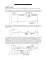
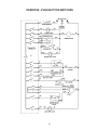
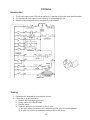
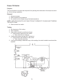
THEORY OF OPERATIONS
NORMAL WASH
When the timer is manually set by the user for NORMAL WASH, CONTACTS 31 and 5 are closed.
When the dishwasher door is closed and latched, the DOOR SWITCHES are closed on the hot and
neutral side of the power supply and power is supplied to the timer motor to advance the timer. (Fig. 1)
120 VAC 60 Hz
TIMER
T
31
BK
DOOR SWITCH
G
W
W/V
CABINET DOOR SWITCH
GROUND
W/V
TIMER MOTOR
Timer CONTACT 5 will be closed for approximately 80 seconds. This provides power to the fill valve to
fill the tub with water. An overfill switch will open to prevent too much water from entering the dishwasher. (Fig. 2)
TIMER
BR/W
BR
5
OVERFILL
SWITCH
W/V
FILL VALVE
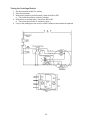
Once the fill valve is turned off, timer CONTACT 3 is closed. Since the dishwasher is in a wash cycle,
timer CONTACT 2 is also closed. Power is supplied through the motor start relay coil, to the run
winding of the drive motor. The motor start relay closes when the coil is energized and power is
supplied through timer CONTACT 2 to the wash winding of the drive motor. (Fig. 3) This causes the
drive motor to run in a clockwise direction. When the pump impeller is driven in the clockwise direction, water is forced from the tub, through the pump assembly and up through the spray arms. Any
detergent that was placed in the bottom cup will be mixed with the water and wash the dishes.
TIMER
1
2
G/Y
DRAIN
Y
WASH
V
RUN
MOTOR
START
RELAY
3
BU/W
1
DRIVE
MOTOR
W/V
Once the wash cycle is completed, timer CONTACTS 3 and 2 open and CONTACT 1 closes. When
CONTACT 3 closes again, power is applied through the motor start relay coil to the run winding of the
drive motor. The motor start relay closes when the coil is energized and power is supplied through
timer CONTACT 1 to the drain winding of the drive motor. This causes the drive motor to run in a
counterclockwise direction. When the pump impeller runs in this direction, water is forced from the tub
thought he drain valve and out the drain hose.
TIMER
1
2
G/Y
DRAIN
Y
WASH
DRIVE
MOTOR
W/V
RUN
V
MOTOR
START
RELAY
3
BU/W
After each wash cycle, the dishwasher will cycle through two (2) rinse cycles. The rinse cycle works
the same as a wash cycle except that no detergent is released into the tub by the detergent dispenser.
DETERGENT DISPENSER OPERATION
One of the cams turned by the timer motor is designed to operate the detergent dispenser. A cam
follower rides in a groove in this cam. When the cam reaches the correct position during the second
wash cycle, the cam follower engages the draw bar in the dispenser assembly. As the draw bar is
pulled up the detergent lid latch releases its hold on the detergent lid, which is forced open by a spring.
A similar operation occurs during the final rinse cycle to release the wetting agent.
DRAW BAR
SPRING
DETERGENT LID
DRAW BAR
LOWER
LID
SPRING
ACTUATOR
LATCH
SLIDE LATCH
SPRING
2
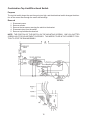
HEATER OPERATION
Timer CONTACT 6 is closed to supply power to the heater during two (2) cycles.
1. During the second WASH cycle to heat the wash water.
2. During the FINAL RINSE cycle for one (1) minute and thirty seconds to heat rinse water.
TIMER
R
19
W/R
W/R
SELECT
SWITCH
OR
W/V
6
HEATER
THERMAL
FUSE
Timer CONTACT 19 will close after the final rinse cycle and, if the user has selected HEATED DRY on
the console, the heater will remain on during the dry cycle.
TIMER
R
19
W/R
W/R
SELECT
SWITCH
OR
W/V
6
THERMAL
FUSE
3
HEATER
-- NOTES --
4
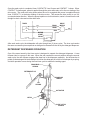
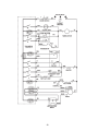
READING ESTERLINE (TIMER SEQUENCE) CHARTS
Introduction
One of the keys to troubleshooting dishwashers is being able to read the Esterline Chart, which is also
known as a Timer Sequence Chart. The timer sequence chart indicates which contacts on the wiring
diagram are closed or open at a given time during the dishwasher cycle. In order to understand what
is happening in each of the dishwasher cycles, the relationship between the timer dial, push-button
switches, Esterline Chart, and the wiring diagram need to be clearly understood. This section will
explain these relationships.
Reading Esterline charts is divided into the following sections:
•
Timer Sequence Chart Description—This is an overview of all the columns on the timer sequence
chart.
•
Timer Dial—Describes how the timer dial corresponds to the intervals on the Esterline chart.
•
Push-Button Switches—Describe how the options the customer selects affect the position of the
switches on the wiring diagram.
•
Timer Contact Positions—Explain how to tell from the Esterline chart the position of the timer
contacts on the wiring diagram during a certain interval of the cycle.
•
How components are energized
•
Troubleshooting
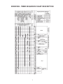
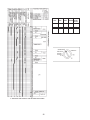
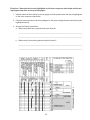
Timer Sequence Chart Description
The first step in being able to read the timer sequence chart is to understand what information is found
on the chart. The following chart, has different areas highlighted, with a description of the information
in each of the areas following the chart.
A. Timer switch numbers—these numbers indicate the timer contact and correspond to the numbers on the wiring diagram; there is no sequence.
B. Timer switch function—this column indicates both primary and intermediate switch functions.
A primary function is when a switch is solely responsible for that function within the dishwasher.
Examples of a primary function of a switch would be heat dry, motor, fill, heat water, wetting
agent dispenser, detergent dispenser, timer motor, clean light, wash, and drain. An intermediate function is when a switch sets up a condition within the circuit to occur if a certain cycle or
option is selected. Examples of an intermediate function of a switch would be heavy/pots,
normal, therm. bypass, and bypass.
C. Terminal code (wire color code)—indicates the color of the wire that is connected to the timer
and goes to the component that performs the function indicated. D. This portion of the Esterline
chart indicates that the contacts within the timer are in the open or closed position at various
intervals. It is important to look at the entire interval because contacts may be open or closed
for only part of the interval as indicated by DI.
E. Detents—Detents are reference points at the beginning of each cycle. When the customer
sets the timer dial, these reference points are a mechanical action that can be felt at the
beginning of each cycle.
F. Intervals—each interval stands for a period of time during the cycle. In this particular chart, the
intervals 1-9 each represent 30 minutes, and intervals 10-53 each represent two-minute intervals. This is indicated by the notes on the side of the chart marked F1 and F2.
5
G. This portion of the chart indicates which events happen at the various intervals in the cycle. In
some cases, more than one event takes place during a particular interval. For example, during
interval 31 (labeled GI) only one event (drain) is taking place during the interval. However, G2
indicates that at interval 25, two events are taking place; the dishwasher is both filling and
washing.
H. Push-Button-Switch—this area indicates what contacts in the program switches are open or
closed on the wiring diagram, depending on the cycles and options chosen by the customer.
The customer may only choose one cycle (e.g., air dry, high temperature wash).
A
F
CYCLES
B
OPTIONS
C
F1
F2
D
G2
D1
G1
G
F
E
6
EXERCISE - TIMER SEQUENCE CHART DESCRIPTION
7
Directions:
Answer the following questions using the Esterline chart on the previous page.
1. What is the switch number for the timer motor?
a. 3
b. 22
c. 1
d. 19
2. What color wire comes out of the timer and goes to the fill valve?
a. Grey
b. White and Red
c. Yellow
d. Brown
3. List the intervals that mark the beginning of each cycle where the customer can feel a mechanical action as the timer dial is being set.
a. ___________
b. ___________
c. ___________
d. ___________
e. ___________
f. ___________
4. How long are each of the intervals on the Esterline chart?
a. 2 minutes
b. 30 minutes
c. Both a and b
d. Information not given on the Esterline chart
5. What event or events are taking place during interval 17?
a. Drain
b. Fill and rinse
c. Fill and detergent dispensing
d. Dry
6. During interval 31 the event taking place is drying.
a. True
b. False
8
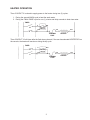
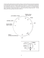
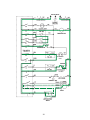
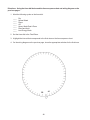
TIMER DIAL
Introduction
When a customer selects a certain cycle on the dishwasher, the customer turns the timer dial to that
position and pushes the corresponding push-button switch to start the dishwasher. If the customer
does not push the corresponding push-button switch to the position to which the timer dial has been
turned, the dishwasher will not complete the cycle to customer expectations or start. For example, if
the customer selects pots and pans wash on the timer dial, and selects the normal wash push-button
switch, the dishwasher will not start.
PUSH-BUTTON
SWITCHES
TIMER
DIAL
Interval Numbers
The interval numbers on the timer sequence chart correspond to a position on the timer dial. Therefore, if a customer tells you that the machine will not fill when the pots and pans cycle is selected, you
can refer to that particular interval on the timer sequence chart to determine the positions of the
switches at that particular interval. The key is to be able to determine what position on the timer dial
corresponds to a particular interval on the timer sequence chart. In orderto do this, think of the timer
dial as a circle with equally spaced increments representing each of the intervals on the timer sequence chart. In this particular model, the timer dial would have 53 increments because there are 53
intervals on the timer sequence chart. On the timer dial there are eight different markings: Off, Delay
Hours, Heavy Wash (Pots and Pans), Normal Wash, Light Wash, Rinse and Hold, Air Dry, Rinse and
Dry. The events on the timer sequence chart and the corresponding intervals can be matched with the
settings on the timer dial.
The last interval is always the OFF position on the timer dial. There are four different wash cycles. The
first wash (which starts at interval 10 on the timer sequence chart) corresponds to the heavy wash/
pots and pans indicator on the timer dial. Notice that although there is one position on the timer dial for
both heavy wash/pots and pans, there are two separate push-button switches. This would indicate
that although they both start at the same interval on the timer sequence chart, there is some difference during the cycle. Therefore, if the customer said the machine would not fill when set to the heavy
wash/pots and pans position, to begin troubleshooting you would look at interval 10 on the timer sequence chart to determine which switches are closed when the timer dial is in that particular setting.
9
10
11
Continuing with matching the intervals with the settings on the timer dial, the normal wash corresponds
to the second wash on the timer sequence chart, which is interval 14. The third wash is the light wash
and corresponds to interval 18. The rinse and hold cycle starts at interval 25 on the timer sequence
chart, and the rinse cycle starts at interval 28. The final rinse cycle is the one in which the wetting
agent is dispensed. The dry cycle starts at interval 33 and continues through interval 53. The dry
setting on the timer dial starts at increment number 33.
12
POTS & PANS
HEAVY WASH
NORMAL WASH
LOW ENERGY
WASH
RINSE & HOLD
RINSE
DRY
OFF
13
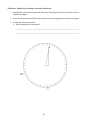
EXERCISE - TIMER DIAL
14
Directions: Using the Esterline chart on the previous page, number the increments on the
timer dial below, and label the intervals at which the following cycles would start. NOTE:
REMEMBER THAT THE DETENTS ON THE ESTERLINE CHART MARK THE BEGINNING OF EACH
CYCLE.
Intervals
• Pots and pans/heavy wash
• Normal wash
• Low energy wash
• Rinse and hold
• Rinse
• Dry
• Off
15
PUSH-BUTTON SWITCH
Introduction
CYCLES
{
{
Besides setting the timer dial, the customer has to select and push a button or buttons on the control
panel for the different cycles and options. The customer may only select on cycle (wash setting) and
that cycle has to match the timer dial setting in order for the dishwasher to perform the action/event
that corresponds to that cycle. Remember, on this model the customer may either select the heavy
wash or the pots and pans program switch if the timer dial is set on heavy wash/pots and pans. If a
customer tries to select more than one cycle using the push-button switches, the previous selection
will always pop up when the next button is depressed. The customer may, however, select as many
options as desired. On this particular model, the customer has two options: high temperature wash,
and air dry. In order to change the options selected, the customer must press the reset button. Unless
the customer pushes the reset button the options will remain the same as previously selected. When
the customer chooses an option, he or she is changing the default setting.
OPTIONS
16
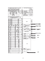
Timer Sequence Chart and Wiring Diagram (Push-Button)
Different switches will be open or closed depending on the cycles and options the customer selects. In
the wiring diagram, all switches are left open (unless it is a normally closed switch), because the wiring
diagram represents the appliance at a state of rest. Therefore, when the customer selects a cycle and
options, something needs to tell us what switches are affected. The timer sequence chart is the tool
that gives us this information.
On the timer sequence chart, the push-button switch box will indicate the positions of the switches for
the various cycles and options. For example, in this particular model there are four switches that are
affected by the selection of a program switch. These four switches are D, F, H, and K. An X indicates
the switch is closed, and an O indicates the switch is open. These switches correspond to switches on
the wiring diagram. Notice on the wiring diagram that the switches are enclosed in a dashed line box
and are labeled “PUSH-BUTTON” or “PB. SW.”
17
If the customer selected heavy wash, high temperature wash, and air dry, switches D and K would be
closed, and switches F and H would be opened. Notice that there is a line that says “Both Options.”
This line gives us the switch positions if both options are selected. You would get the same switch
positions by reading lines 5 and 6.
18
If the customer selected a low energy wash and air dry, switches D and K would be closed and H
would be in the open position. Switch F would be closed since the customer had to select the reset
before choosing any options. These switches, not affected by the customer selections would remain
as indicated in the reset option.
19
If the customer selected pots and pans and wanted no other options, the customer would need to
select the pots and pans and reset option buttons. This would close contacts K, F, and H. Switches F
and H would be closed because in order to clear to previous options, the customer would have to
select the reset button.
20
EXERCISE - PUSH-BUTTON SWITCHES
21
POTS &
PANS
22
HEAVY
WASH
NORMAL HI TEMP ENERGY
WASH
WASHING SAVING
AIR DRY
Directions: Based on the Esterline chart and the wiring diagram on the previous pages answer
the following questions.
1. What option(s) are available on this model?
a. Low energy wash
b. Energy saving air dry
c. High temperature wash
d. Both b and c
2. If the customer selected the air dry option with a normal wash, indicate the position (open or
closed) of the following switches.
a. Switch D—
b. Switch F—
c. Switch H—
3. Using the illustration below, if a customer wanted a low energy wash cycle and air dry, the timer
dial would be set on low energy wash, and the following push-buttons would be selected.
a. Normal wash, and energy saving air dry
b. Low energy wash and energy saving air dry
c. Heavy wash and normal wash
d. None of the above
4. The customer cannot select more than one option at a time.
a. True
b. False
5. On the wiring diagram on the previous page, mark the push-button switches that would be
closed if the customer selected the pots and pans cycle and no other options.
23
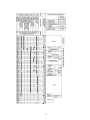
TIMER CONTACT POSITIONS
Introduction
The purpose of the timer sequence (Esterline) chart is to indicate the position of the timer contacts
during the different events of the cycles. This chart indicates the path of current flow through the
appliance at any given time. In order to interpret the timer sequence chart, it is important to understand
how it interacts with a wiring diagram.
Switch Positions
A solid black bar means that the switch is closed. No bar, or a white space, means that the switch is
open. A switch can be open or closed for part of an interval. This is indicated by a black bar for only
part of the interval space. An X means that at that point in the timer, the switch could either be open or
closed. This typically happens when a switch is either about to open or close, but since it takes some
time for that action to occur, the switch position cannot be predicted at that time.
INTERVAL LINE
SWITCH CLOSED
SWITCH CLOSED FOR
PART OF AN INTERVAL
SWITCH OPEN
24
Timer Sequence Chart Interpretation
The way to read a timer sequence chart is by intervals. Determine what event or events are taking
place during that interval. The space above the interval line indicates the position of the timer contacts
during that interval. These positions then determine the positions of the switches on the wiring diagram.
For example, let’s read interval 4. There is only one event taking place during this interval, and that is
a delay before the dishwasher starts. During this interval four switches are closed. The switch numbers are 3, 31, 22, and 2. Which means that these switches should be closed on the wiring diagram.
25
26
Look at interval 13. The dishwasher is draining in this event. In this interval, the timer contacts that are
closed are 3, 5, 33, 27, 22, 2, and 1. Of these closed contacts, notice that all switches except switch
22 are closed for only part of the interval. These switches would still be considered closed on the
wiring diagram. Notice that the terminal wire color is also indicated on the wiring diagram next to the
corresponding switch. This indicates the color of the wire that comes out of the timer to go to the
component.
27
28
EXERCISE - TIMER CONTACT POSITIONS
29
30
Directions: Answer the following questions based on the Esterline chart and wiring diagram
on the previous pages.
1. During the entire interval 6, which timer contacts are closed?
a. 2, 3, 5, 22, 35, 36
b. 2, 5, 22, 35, 36
c. 5, 6, 28
d. 1, 3, 22
2. An “X” indicates that the switch may be in the open or closed position at the interval.
a. True
b. False
3. In interval 22, what switch(es) are only closed for a portion of the interval?
a. 1, 2, and 3
b. 3 and 19
c. 2 and 3
d. Both a and b
4. The same timer contacts are closed in intervals 28 and 31.
a. True
b. False
5. Circle the timer contacts and push-button switches that would be closed on the wiring diagram
on the previous page if the customer selected a normal wash with an air dry option, and the
machine just started the final rinse. HINT: YOU WILL NEED WATER IN THE DISHWASHER
TO RINSE.
31
INTERPRETING INTERVALS
Introduction
During each interval the timer switches are opened or closed to energize the various components
used in the different events. During each interval, one or more events may take place. it is important
to look at the entire interval, as switch positions may change during the interval. One of the most
difficult intervals to interpret is when a thermohold takes place. To understand what happens during a
thermohold, divide the interval into three parts and look at the wiring diagram at the beginning, middle,
and end of the interval.
32
Thermohold
Beginning Third of the Interval
The first thermohold is in interval 11, during the pots and pans cycle. The switches closed during the
first third of the interval are the door switches, timer contacts 22, 28, 30, 33, 6, 2, and 3. Because the
pots and pans cycle is selected, push-button switch K is closed. Timer contact 22 provides a direct
path of electrical power to the timer motor. Therefore, the timer motor is advancing.
Contact 28 is the heavy bypass. Since this is the pots and pans cycle, this switch isn’t used in this
circuit. This switch sets up a condition that if heavy wash was selected, it would provide a way for the
thermohold to be bypassed. The difference between the pots and pans cycle and the heavy wash
cycle is that the pots and pans cycle has a thermohold during the first wash.
Contact 30 is closed, which provides power to the thermostat. The thermostat is a normally open
switch which closes when the water temperature reaches 130-140 degrees. At this point, the thermostat is open, so power will not go through to the timer motor. Contact 33, push-button, K, and contact
6 are closed, which completes a circuit through the hi-limit thermostat (which is normally closed) to
energize the heater. At this time, the heater is heating the water. Notice that the current will not
energize the delay light at this part of the interval. This is because the delay light is in a parallel circuit
with timer switch 22 going to the timer motor. Because current will take the path of least resistance, it
will go through switch 22 to the timer motor. Therefore, the delay light will not come on. Contacts 3 and
2 are closed, which means that the water is circulating at this time. Remember, contact 2 is closed, but
the current only goes through that switch for a few seconds to energize the motor start windings, and
as the motor start relay contacts drop out, the motor continues to run through the motor start relay coil
and the run windings of the motor.
33
DELAY START
LIGHT
34
Middle Third of the Interval
During the middle third of interval 11, contact 22 opens. (All other switches remain as they were in the
first third of the interval.) This stops the timer motor. Current now can go through the delay light to the
timer. But since the neon light uses so much of the voltage, there will not be enough voltage to energize
the timer motor. The heater is energized so the water continues to heat. Contact 30 is closed, but until
the water reaches 130-140 degrees, the thermostat will not close. Contacts 2 and 3 are closed, which
means the motor is running in the wash direction.
NOTE: THIS PART OF THE INTERVAL WILL CONTINUE UNTIL THE WATER TEMPERATURE
REACHES 130-140 DEGREES, WHICH MEANS THAT IT COULD TAKE A CONSIDERABLE
AMOUNT OF TIME.
DELAY START
LIGHT
35
Last Third of the Interval
The last third of the interval begins when the water finally reaches 130-140 degrees. When the water
reaches this temperature, the thermostat closes and provides a complete circuit to the timer motor.
This causes the timer motor to advance, which caused contact 22 to once again close, and the timer
motor continues to advance. At this time, the delay light will turn off, because the thermostat will
provide a path of lesser resistance to the timer motor.
DELAY START
LIGHT
36
EXERCISE - INTERPRETING INTERVALS
DELAY START
LIGHT
37
38
Directions: Using the timer sequence chart and the wiring diagram on the previous pages,
complete the chart and answer the question.
1. What cycle setting and/or options would allow you to bypass the third thermohold interval 29?
___________________________________________________________________________
39
PRACTICE EXERCISE - 1
40
41
Directions: Based on the setting on the timer dial below:
1. Highlight the interval that corresponds to the timer dial setting on the timer sequence chart on
the previous pages.
2. Close the corresponding switches for that interval on the wiring diagram on the previous pages.
3. Answer the following questions:
a. What components are energized?
________________________________________________________________________
________________________________________________________________________
42
PRACTICE EXERCISE - 2
43
44
Directions: Based on the interval highlighted on the timer sequence chart below and the wiring diagram and chart on the previous pages:
1. Indicate where the timer dial (on previous page) would be positioned for the interval highlighted
on the timer sequence chart below.
2. Close the timer switches on the wiring diagram on the previous page that are closed during the
highlighted interval.
3. Answer the following questions:
a. What components are energized during this interval?
________________________________________________________________________
________________________________________________________________________
b. What event(s) is/are taking place during this interval?
________________________________________________________________________
________________________________________________________________________
45
PRACTICE EXERCISE - 3
46
47
Directions: Using the timer dial below and the timer sequence chart and wiring diagram on the
previous pages:
1. Mark the following cycles on the timer dial:
____
____
____
____
____
____
____
Dry
Normal Wash
Rinse
Off
Heavy Wash/Pots & Pans
Rinse and Hold
Low Energy Wash
2. Set the timer dial to the Final Rinse.
3. Highlight the interval that corresponds to the final rinse on the timer sequence chart.
4. On the wiring diagram on the previous page, close the appropriate switches for the final rinse.
58
48
41
DISWASHER COMPONENT TESTING AND/OR
DISASSEMBLY
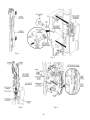
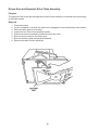
Wetting Agent and Detergent Dispensers
Introduction
The purpose of the wetting agent dispenser and detergent dispenser is to release the detergent and
wetting agent at the appropriate times during the wash and/or rinse cycles.
Dishwasher Dispenser Disassembly
1. Remove the drawbar spring. (Fig. A)
2. Align the lower drawbar holes with the locking tabs and remove the upper and lower drawbars.
As you do, note the locating tabs behind them and how they align with their respective locating
holes. (Fig. B)
3. Slide the drawbars apart. (Fig. C)
4. Turn the wet agent cap and seal assembly counterclockwise and remove it. (Fig. D)
5. Remove the seal from the cap.
6. Use Special Tool - Part No. 303918 or a ¾” socket to press over the attaching tabs
in the wet agent cap opening. Remove wet agent dispenser assembly.
7. Remove wet agent dispenser actuator by spreading the two (2) locking tabs. (Fig. E)
8. Remove the upper and lower slides from the wet agent dispenser actuator.
9. Remove the diaphragm spring and diaphragm.
10. Use a screwdriver to gently release the lower tab and remove the detergent door
actuator assembly. As you do, note the position of the door latch level through the hole in the
lower slide. (Fig. F)
11. Remove the upper slide, the slide spring and the lower slide. (Fig. G)
Fig. A
Fig. B
49
Fig. C
Fig. D
Fig. F
Fig. E
50
Dishwasher Dispenser Assembly
1. Assembly the upper slide, slide spring
and lower slide to the detergent
door actuator. (Fig. G)
2. Pass the detergent door latch
lever through the panel making
sure to turn the hook of the latch toward
the detergent door. Snap the detergent
door latch snap onto the door latch lever.
(Fig.F)
3. The door latch lever must pass through
the opening in the lower slide. Press the
actuator assembly into position until the
upper and lower tabs engage.
4. Insert the diaphragm and diaphragm
spring into the wet agent dispenser. Seat
the diaphragm flush with the surface of
the dispenser. (Fig. E)
5. Install the upper and lower slides into the
wet agent dispenser actuator.
6. Press the wet agent dispenser actuator
into position on the dispenser so the locking tabs engage.
Fig. G
7. Press the wet agent dispenser assembly
into position so the locking tabs engage
the wet agent cap opening. No tool is
needed for assembly. (Fig. D)
8. Install the seal on the wet agent cap.
9. Insert the wet agent cap. Turn it clockwise and close it.
10. Slide the upper and lower drawbars
together. (Fig. C)
11. Move all slides in both assemblies fully
down. Keep the drawbars slid fully together and align the drawbar holes over
the locking tabs. Look behind the draw
bars and make sure to engage the locating tabs with their respective locating
holes. Press the drawbars into position
and slide them upward behind the locking
tab ears. (Fig. B)
12. Install the drawbar spring. (Fig. A)
13. Install the drip cover by snapping it into
place.
51
Door Switch
Introduction
1. The door switch is the first switch in the wiring diagram.
2. Without 120 volts passing through the door switch, the other components in the dishwasher
will not work.
3. Its purpose is to stop all dishwasher functions if the door is open.
4. There are two door switches in plastic tub models.
a. One breaks the LI circuit, and the other breaks the neutral circuit.
1) This is a double safety to prevent any current from going to the dishwasher when the
door is open.
Testing
1.
2.
3.
a.
Disconnect dishwasher from electrical source
Remove the harness leads
Test for continuity between terminals of each switch
Wit the button depressed (door switch closed), there should be continuity (switch is closed)
a. With the button up (door switch open), there should be no continuity (switch is open)
52
Push-Button Switches
Introduction
1. The push-button switches provide the customer with a selection of different cycles and
options.
2. The push-buttons selected by the customer will determine the cycles and options of the dish
washer.
Testing
1. Disconnect dishwasher from electrical source.
2. Remove all wires from the switch.
3. Identify each of the switches on the push-button switch by using the timer sequence chart
(determine the wire color going to each terminal.)
4. Set the meter on the Rx1 scale.
5. Zero the meter.
6. Check each individual switch without depressing the button.
a. Touch the probes to the terminals of the switches to be tested.
1) Record whether you get an open or closed read for each switch.
7. The push-button switch is good if the depressed switch read is opposite of the nondepressed
read.
53
Indicator Lights
Introduction
1. The indicator light is energized with 120 volts.
2. Indicator lights are neon bulbs that indicate of the control panel which stage of the cycle the
dishwasher is in (i.e., delay, clean).
a. If given another path for current flow, current will not go through the neon bulb because of
the high resistance.
b. Current passing through an indicator light will not be great enough to energize other electrical components in the electrical path.
Testing
1. To check the indicator light for resistance:
a. Disconnect the dishwasher from electrical source.
b. Check to make sure the 120 volts load in series with the indicator light is working.
1) Check that this load operates in another circuit.
c. Check for 120 volts into the indicator light and on the other side of the load in the circuit.
54
Timer
Introduction
1. The timer progresses the dishwasher through the cycle, closing contacts to activate individual
components as needed.
2. The timer needs 120 volts, or the unit will not advance.
55
Testing—Timer Switches
1.
2.
3.
4.
Disconnect dishwasher from electrical source.
Disconnect all harness leads from the timer.
Determine the timer contact to be tested.
Select a cycle that closes the selected the selected switch contacts in the timer (move the
cycle control knob to the selected setting.)
5. Set the meter on the Rxl scale.
6. Zero the meter.
7. Touch the meter probes to the selected terminals.
a. The selected switch contacts should show continuity (0 resistance.)
Testing—Timer Motor
1.
2.
3.
4.
5.
Disconnect dishwasher from electrical source.
Disconnect the timer motor at the disconnect plug.
Set the meter to the Rx1K scale.
Zero the meter.
Touch the meter probes to the contacts inside the disconnect plug attached to the timer motor
leads.
a. A good motor should show 1900 to 29000 ohms.
NOTE: THE MOTOR IS NO LONGER SERVICEABLE AS A PART, IF THE TIMER DOES NOT ADVANCE THE TIMER IS REPLACED.
56
Thermostat (Water Heating)
Introduction
1. The water temperature thermostat is usually a normally open switch with 3/16 inch terminals.
2. It closes when the temperature of the water reaches 135-145 degrees.
3. When the thermostat closes, it allows the current to reach the timer motor, and the cycle will
continue.
4. Its purpose is to complete a circuit to the timer motor after the water temperature reaches a
certain temperature during any thermohold.
Operating
Thermostat
Testing
1. Disconnect dishwasher from electrical source.
2. Remove the wires from the thermostat.
3. Place a thermometer in a pan of water and heat on a range until the temperature reaches 135140 degrees.
4. Remove thermostat from dishwasher.
5. Set the meter to the Rx1 scale.
6. Zero the meter.
7. The thermostat should read infinite resistance (open) at room temperature outside of the heated
pan.
a. Thermostat should close (the ohmmeter will read continuity) when the water is between
140 degrees and 150 degrees.
57
Thermostat (High Limit)
Introduction
1. Normally closed thermo/switch with 1/4 inch terminals.
2. This switch is a safety switch that opens if the internal temperatures of the dishwasher reach
185 degrees and shut down the heater.
Testing
1. Disconnect dishwasher from electrical.
2. Remove wires from thermostat.
3. Place a thermometer in a pan of water and heat on range until the temperature
reaches 185 degrees.
4. Remove thermostat from dishwasher.
5. Set meter to the Rx1 scale.
6. Zero the meter.
7. The thermostat should read continuity at room temperature.
8. Attach ohmmeter leads to the terminals and hold the thermostat against the
outside of the heated pan.
a. Thermostat should open (read infinite resistance.)
58
Fill Valve
Introduction
1. The fill valve opens when 120 volts is applied to it, and then it lets water enter the dishwasher.
2. The mechanical water valve is held closed by an electromagnetic coil.
3. When the electromagnetic coil is energized, the valve opens.
Testing
1. Disconnect the dishwasher from electrical source.
2. Check coil for proper resistance.
a. Remove the harness plug from coil.
b. Set the meter to the Rx100 scale.
c. Zero the meter.
d. Touch the probes to the terminals on the fill valve.
1) An open (infinite resistance) coil is defective and the valve should be replaced.
2) A good coil will have a resistance reading of 500 to 800 ohms.
59
Overfill Switch
Introduction
1. If the timer fails to advance past the fill position, the overfill switch monitors the water level so
the dishwasher doesn’t fill to full.
Testing
1.
2.
3.
4.
5.
Disconnect dishwasher from electrical source.
Disconnect the electrical leads from the overfill switch.
Set the meter on the Rx1 scale.
Zero the meter.
Touch the probes to the switch terminal.
a. When the float is in the DOWN position, there should be continuity through the switch (0
resistance).
60
Heating Element
Introduction
1. The heating element is used both during wash cycles and the heat dry cycles.
2. The purpose of the heater is to heat the water during the wash cycle and/or to heat the air
during the dry cycle.
Testing
CAUTION: ONLY TEST THE HEATING ELEMENT AT AMBIENT TEMPERATURE SO YOU DO NOT
BURN YOURSELF, AND ALSO TO OBTAIN THE CORRECT READING.
1. Disconnect dishwasher form electrical source.
2. Disconnect harness leads from the heating element.
3. Test central core or element:
a. Set the meter.
b. Zero the meter.
c. Touch the meter probes to the terminals of the heating element.
1) A good heating element will read between 16 and 20 ohms.
4. Test core to shell:
a. Set the meter on the Rx10K scale.
b. Zero the meter.
c. Touch on of the probes to one terminal and the other probe to the shell of the element.
1) There should be no continuity (infinite resistance.)
d. Touch one of the probes to the other terminal and the other probe to the shell of the
element.
1) There should be no continuity (infinite resistance.)
61
Motor Start Relay
Introduction
1. The motor start relay protects the motor.
2. The motor start relay is a “current sensitive” relay.
3. At instant of start, current going through the coil is high enough o close the normally open
contact of the relay.
a. At that point, the timer contact would direct the current to either the “wash” or the “drain”
start winding.
4. One or two seconds after the motor starts, the current through the relay drops back to its
normal operating current, which is too low to keep the normally open contact closed.
a. The motor will continue to run through the coil windings of the motor start relay.
5. If the start winds do not drop out, the motor will burn up.
Testing
1.
2.
3.
4.
5.
Disconnect dishwasher from electrical source.
Disconnect the harness leads and remove the relay.
Set the meter on the Rx1 scale.
Zero the meter.
Turn the relay upside down and check between the contacts for continuity.
a. The relay should be closed and read 0 resistance in this position.
6. Turn the relay right side up and check between the contacts for continuity.
a. The relay should be open in this position and read infinite resistance.
7. Measure resistance through the coil by placing the probes on contacts.
a. A good coil will read less than 1 ohm.
62
Motor
Introduction
1. The motor provides the power for the pump to wash or drain.
2. Timer contact 3 is the direct switch to the motor.
3. Timer contacts 1 and 2 tell the motor in which direction to run.
a. Timer contact 2 is closed to start the motor into the wash direction.
b. Timer contact 1 is closed to start the motor into the drain direction.
4. When the motor switches directions, the motor will completely stop before starting in the
opposite direction.
63
Testing
1. Disconnect dishwasher from its electrical source.
2. Disconnect the harness leads from the drive motor.
3. Check continuity of motor windings:
a. Set the meter to the Rx1 scale.
b. Zero the meter.
c. Touch the meter probes to the proper terminals for each winding in the disconnect plug:
1) Drain start winding—BK to W should read 4-7 ohms resistance.
2) Wash start winding—Y to W should read 4-7 ohms resistance.
3) Run winding—BU to W should read 2-4 ohms resistance.
4. Ground test:
a. Set the meter to the Rx10K scale.
b. Touch one probe to one of the terminals in the disconnect plug and the other to the motor
housing.
1) There should be no continuity (infinite resistance.)
c. Touch one probe to the other disconnect plug terminal and the other to the motor housing
1) There should be no continuity (infinite resistance.)
64
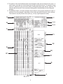
EXERCISE - DISHWASHER COMPONENT TESTING
METER
SETTING
TEST/CHECK
Door Open
Rx1
Check for Continuity
Door Closed
Rx1
Check for Continuity
Push-Button
Switch
Heavy Wash
Air Dry
Rx1
Check between:
P/BK
T/R
Y/BU
W/BU
R
W/R
G/BK
P/BK
Timer
Timer Set
Anywhere in
Delay
Rx1
Check between:
T
W/BK
T
T/R
T
W/BU
W/BU
BU
V
Y
T
BU/BK
Thermostat
(3/16” terminal)
Room Temp.
Rx1
Contact Position
145°F
Rx1
Contact Position
Room Temp.
Rx1
Contact Position
185°F
Rx1
Contact Position
Tub Empty
Rx1
Position of Switch
Tub Full
Rx1
Position of Switch
COMPONENT
CONDITION
Door Switch
Thermostat
(1/4” terminal)
Float Switch
Fill Valve
Rx100
Ohms Reading
Heating
Element
Rx10K
Test for Ground
Rx1
Ohms Reading
Right Side Up
Rx1
Ohms Reading
Upside Down
Rx1
Ohms Reading
Coil
Rx1
Ohms Reading
Test All
Windings
Rx1
Ohms reading for
each winding and
indicate which is the
run winding.
Motor Start
Relay
Motor
65
RESULTS
--NOTES --
66
THEORY OF OPERATION
Instant of Start
When the start button is pushed, a circuit is completed to the run windings of the motor. A parallel
circuit through the directional switch to the start windings of the motor is also completed.
67
Running—Going Down or Coming up
After the start switch is released and the ram moves down about one inch, the top limit/directional
switch changes position (the movement of the ram causes this action) and maintains a circuit to the
run windings of the motor. The other internal switch of the top limit/directional switch positions itself to
complete a circuit to the CCW start windings (ram up direction). This condition is necessary when the
ram stalls, it will change the direction of the ram.
IMPORTANT NOTE: THE DRAWER TILT SWITCH IS HELD OPEN IF THE DRAWER IS IN THE
PROPER POSITION. IF THE DRAWER TILTS, THE DRAWER TILT SWITCH WILL CLOSE AND
COMPLETE THE CIRCUIT.
68
Instant of Stall (Reversing from Down Coming Up)
When the ram reaches the end of its downward movement, the motor stalls. When the motor stalls, it
causes the motor centrifugal switch to change position(s), completing a circuit through the CCW motor
windings (ram up direction). This circuit is set up through the top limit/directional switch, which is
activated by the ram. At this point, the motor reverses direction and the ram moves in the upward
direction.
69
Instant of Stop
When the ram goes completely up, the ram hits the top limit switch, which causes it to open. This stops
the ram at its top position. At this point, the ram also changes the position of the directional switch
from the up start winding, which prepares it for the next cycle.
70
Drawer Tilt Switch
If the drawer is forced open 1/4 inch or more when the ram compacts the trash in the drawer, the
drawer tilt switch closes and completes a circuit to the CCW (ram up direction) start windings. This
causes the motor to stall, which in turn causes the motor centrifugal switch to change positions. The
motor then restarts in the CCW direction and returns the ram to the up position.
71
-- NOTES --
72
DISASSEMBLY AND TESTING
Ram
Purpose
The purpose of the ram is to compact the trash.
Removal
1.
2.
3.
4.
5.
6.
Remove compactor drawer.
Remove console.
Remove top of compactor.
Put console back in place without screws.
Put drawer back in place.
Start compactor.
a. When ram bottoms out and starts coming back up, press and hold the start button.
b. Hold start button until ram completely unthreads itself from the power screws.
7. Disconnect unit from electrical supply.
8. Lift ram from cabinet housing.
73
ON, OFF/LOCK Switch
Purpose
The purpose of the ON, OFF/LOCK switch is to prevent the trash compactor from being operated
unintentionally.
Removal
1.
2.
3.
4.
Disconnect power.
Remove compactor drawer.
Pry off switch cover from front panel with flat screwdriver.
Remove wires from switch.
Testing
1. Turn ohmmeter to lowest setting.
2. Zero ohmmeter.
3. Turn switch to OFF position.
a. Check between the two switch terminals.
1) There should be no continuity (open.)
4. Turn switch to ON position.
a. Check between the two switch terminals.
1) There should be continuity (closed.)
5. If any of the readings are incorrect, the switch is defective and needs to be replaced.
74
ON, OFF, START Switch
Purpose
The purpose of this switch is to turn ON and START the unit or to turn OFF the unit.
Removal
1.
2.
3.
4.
Disconnect the power.
Remove console screws.
Tilt the console outward.
Remove the wires from the switch.
Testing
1. Set ohmmeter to the Rx1 scale.
2. Zero ohmmeter.
3. Select the OFF position.
a. Check between terminals TR and V
1) There should be no continuity (open.)
b. Check between terminals V and Y
1) There should be no continuity (open.)
4. Select the ON position.
a. Check between terminals TR and V
1) There should be continuity (closed.)
b. Check between terminals V and Y
1) There should be no continuity (open.)
5. Select the ON position and depress the START button.
a. Check between terminals TR and V
1) There should be continuity (closed.)
b. Check between terminals V and Y
1) There should be continuity (closed.)
6. If any of the readings are incorrect, the switch is defective and should be replaced.
75
Combination Top Limit/Directional Switch
Purpose
The top limit switch keeps the ram from going too high, and the directional switch changes the direction of the current flow through the motor start windings.
Removal
1.
2.
3.
4.
5.
Disconnect power.
Remove console.
Remove the two screws securing the switch to the bracket.
Disconnect wires from the switch.
Remove top limit/directional switch.
NOTE: THE POSITION OF THE SWITCH ON THE MOUNTING SCREWS. ONE IS A SLOTTED
SCREW HOLE FOR ADJUSTMENT PURPOSES. THIS NEEDS TO BE IN THE CORRECT POSITION TO STOP THE RAM ASSEMBLY.
76
Testing
1. Testing of this switch is done when the ram is in three different positions. The position of the
ram is indicated by the number of clicks when pressing the actuator:
a. Ram has traveled downward at least 3/4 inch (actuator released.)
b. Ram has traveled downward 1/2 inch (actuator pressed to the first click.)
c. Ram is at upper most position (actuator pressed to the second click.)
2. Set the ohmmeter to the Rx1 scale.
3. Zero the ohmmeter.
4. Perform the tests using the terminals marked on the switch.
5. With the actuator released (plunger extended all the way) check between the following termi
nals:
a. Terminal GY to Y
1) This terminal should be closed.
b. Terminal R to Y
1) This terminal should be open.
c. Terminal V to BR
1) This terminal should be closed.
6. With the actuator pressed to the first click (plunger depressed halfway), check between the
following terminals:
a. Terminal GY to Y
1) This terminal should be open.
b. Terminal R to Y
1) This terminal should be closed.
c. Terminal V to BR
1) This terminal should be closed.
7. With the actuator pressed tot he second click (plunger depressed all the way), check between
the following terminals:
a. Terminal GY to Y
1) This terminal should be open.
b. Terminal R to Y
1) This terminal should be closed.
c. Terminal V to BR
1) This terminal should be open.
8. If any of the terminals have an incorrect read, the switch is defective and needs to be replaced.
77
Drawer Safety Switch
Purpose
The drawer safety switch prevents the compactor from operating if the drawer is open.
Removal
1. Disconnect power.
2. Remove drawer from compactor Remove cardboard shield on the right-hand side of drawer
opening.
3. Pry out switch from cabinet with flat head screwdriver.
NOTE: WHEN PRYING SWITCH OUT WHILE TRYING TO REMOVE IT, YOU HAVE TO BREAK THE
SWITCH TABS.
4. Remove wires from switch.
Testing
1. Set ohmmeter to Rx1 scale.
2. Zero ohmmeter.
3. Close switch by pushing in plunger.
a. Check between terminals on the switch.
1) There should be continuity.
4. Open switch by releasing plunger.
a. Check between terminals on switch.
1) There should be no continuity.
5. If any of the terminals have an incorrect read, the switch is defective and needs to be replaced.
78
Drawer Tilt Switch
Purpose
The door tilt switch is to prevent the compactor from jamming when the drawer is forced open as much
as 1/4 inch during campaction.
Removal
1. Disconnect power.
2. Remove drawer from compactor.
3. Pry switch from front flange using a flat head screwdriver.
NOTE: WHEN PRYING SWITCH OUT WHILE TRYING TO REMOVE IT, YOU MAY HAVE TO BREAK
THE SWITCH TABS.
4. Remove wires from switch.
Testing
1. Set ohmmeter to Rx1 setting.
2. Zero ohmmeter.
3. Open switch contacts by pushing in plunger.
a. Check between terminals on the switch.
1) There should be no continuity.
4. Close switch contacts (plunger NOT pushed in.)
a. Check between the terminals on the switch.
1) There should be continuity.
5. If an incorrect reading is obtained for any of the readings, the switch is defective and should be
replaced.
79
Driven Gear and Sprocket Drive Chain Assembly
Purpose
The purpose of the driven gear and sprocket and drive chain assembly is to transfer the motor energy
to the power screws.
Removal
1.
2.
3.
4.
5.
6.
7.
8.
Disconnect power.
Lay the compactor on its front; be careful not to damage the loose switch wires and switches.
Remove bottom panel (five screws.)
Loosen the four drive-mount assembly screws.
Slide the drive-mount assembly forward to loosen the chain.
Remove the clip ring from the driven gear.
Remove the driven gear and sprocket assembly.
Remove the chain from the sprockets.
80
Power Screws and Sprockets
Purpose
The ram rides up and down on the power screws as they turn.
Removal
1.
2.
3.
4.
5.
Disconnect power.
Lay the compactor on its front; be careful not to damage the loose switch wires and switches.
Remove bottom panel (five screws.)
Remove power screw flange screws from base.
Slide out or unthread the power screws.
NOTE: BE CAREFUL FOT TO LOSE THE RAM STOP BUSHINGS. ALSO, TAKE CARE NOT TO
GET THE LUBRICANT FROM THE POWER SCREWS ON OTHER SURFACES.
81
Motor Assembly
Purpose
1. The motor assembly consists of the:
a. Centrifugal switch—which completes a circuit to start the motor windings.
b. Motor—which provides the power to move the ram in the appropriate direction.
c. Drive gear—which interlocks with the driven gear.
Removal—Motor and Centrifugal Switch
1.
2.
3.
4.
5.
6.
7.
8.
9.
10.
Disconnect power.
Lay compactor on its front; be careful not to damage the loose switch wires.
Remove bottom panel.
Loosen motor bracket screws.
Slide motor forward.
Remove driven gear and sprocket assembly.
Remove motor bracket from base.
Disconnect harness wires from centrifugal switch.
Remove wires from centrifugal switch.
Remove centrifugal switch from motor by removing the two mounting screws.
NOTE: USE CAUTION WHEN REMOVING THE SWITCH, BECAUSE THE SWITCH IS IN TWO
PIECES.
Testing the Motor
1. Set the ohmmeter at the Rx1 setting.
2. Zero the ohmmeter.
3. Check the motor for ground.
a. All terminals grounded to the metal frame should show an open circuit.
1) If they do not show an open circuit, the motor sould be replaced.
4. Check terminals GY to BR
a. Should read 1 to 4 ohms.
5. Check terminals R to BR
a. Should read 1 to 4 ohms.
6. Check between terminals W to Y
a. Should read 1 to 3 ohms.
7. Check between terminals Y to BU
a. Should read 1 to 3 ohms.
82
Testing the Centrifugal Switch
1. Set the ohmmeter at the Rx1 setting.
2. Zero the ohmmeter.
3. With button pushed in (switch closed,) check from BU to BR.
a. The switch should have continuity (closed.)
4. With button out (switch open,) check from BU to BR.
a. The switch should have no continuity (open.)
5. If any of the readings are not correct, switch is defective and should be replaced.
83
Reassembly
1. When reassembling the trash compactor, install the components in the following order:
a. Centrifugal switch to motor.
b. Motor into frame (do not tighten.)
c. Power screws (remember to put chain around sprocket before tightening power screws.)
d. Tighten and adjust motor tension (install remaining bolts.)
e. Install directional switch.
f. Install drawer safety switch.
g. Install tilt switch.
h. Install key lock switch.
i. Install ram (lever is to front of ram.)
j. Install program switch.
k. Set console in place.
l. Thread on ram.
1) Turn unit on and start.
2) Unit should stop with ram 1/2 inch from the top, if not, adjust the top limit/directional
switch.
m. Install top cover.
n. Tighten console.
o. Put in drawer.
84
EXERCISE—PROBLEM # 1
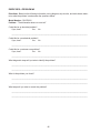
Directions: Based on the following information, wiring diagram, strip circuits, and tech sheets, determine what the problem is and answer the questions below.
Model Number: DU8700XY
Problem: “The dishwasher does not drain the water from the tub.”
Could this be an electrical problem?
If yes, how?
Yes
No
____________________________________________________________________________
Could this be a mechanical problem?
If yes, how?
Yes
No
____________________________________________________________________________
Could this be a customer use problem?
If yes, how?
Yes
No
____________________________________________________________________________
What diagnostic steps will you take to identify the problem?
____________________________________________________________________________
____________________________________________________________________________
What is the problem you found?
____________________________________________________________________________
____________________________________________________________________________
What steps will you take to correct the problem?
____________________________________________________________________________
____________________________________________________________________________
85
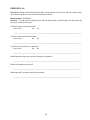
EXERCISES—PROBLEM #2
Directions: Based on the following information, wiring diagram, strip circuits, and tech sheets, determine what the problem is and answer the questions below.
Model Number: DU8700XY
Problem: “The dishwasher does not run at all.”
Could this be an electrical problem?
If yes, how?
Yes
No
____________________________________________________________________________
Could this be a mechanical problem?
If yes, how?
Yes
No
____________________________________________________________________________
Could this be a customer use problem?
If yes, how?
Yes
No
____________________________________________________________________________
What diagnostic steps will you take to identify the problem?
____________________________________________________________________________
____________________________________________________________________________
What is the problem you found?
____________________________________________________________________________
____________________________________________________________________________
What steps will you take to correct the problem?
____________________________________________________________________________
____________________________________________________________________________
86
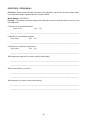
EXERCISES—# 3
Directions: Based on the following information, wiring diagram, strip circuits, and tech sheets, determine what the problem is and answer the questions below.
Model Number: DU8700XY
Problem: “The dishwasher does not fill with water.”
Could this be an electrical problem?
If yes, how?
Yes
No
____________________________________________________________________________
Could this be a mechanical problem?
If yes, how?
Yes
No
____________________________________________________________________________
Could this be a customer use problem?
If yes, how?
Yes
No
____________________________________________________________________________
What diagnostic steps will you take to identify the problem?
____________________________________________________________________________
____________________________________________________________________________
What is the problem you found?
____________________________________________________________________________
____________________________________________________________________________
What steps will you take to correct the problem?
____________________________________________________________________________
____________________________________________________________________________
87
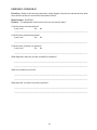
EXERCISE—#4
Directions: Based on the following information, wiring diagram, strip circuits, and tech sheets, determine what the problem is and answer the questions below.
Model Number: DU8700XY
Problem: “The dishwasher does not start if I select the Pots and Pans cycle. It will start if I turn the
timer to the Normal cycle.”
Could this be an electrical problem?
If yes, how?
Yes
No
____________________________________________________________________________
Could this be a mechanical problem?
If yes, how?
Yes
No
____________________________________________________________________________
Could this be a customer use problem?
If yes, how?
Yes
No
____________________________________________________________________________
What diagnostic steps will you take to identify the problem?
____________________________________________________________________________
____________________________________________________________________________
What is the problem you found?
____________________________________________________________________________
____________________________________________________________________________
What steps will you take to correct the problem?
____________________________________________________________________________
____________________________________________________________________________
88
EXERCISES—#5
Directions: Based on the following information, wiring diagram, strip circuits, and tech sheets, determine what the problem is and answer the questions below.
Model Number: DU8700XY
Problem: “If I select the Low Energy cycle with the delay option, the dishwasher will start when the
timer gets to the Normal cycle.”
Could this be an electrical problem?
If yes, how?
Yes
No
____________________________________________________________________________
Could this be a mechanical problem?
If yes, how?
Yes
No
____________________________________________________________________________
Could this be a customer use problem?
If yes, how?
Yes
No
____________________________________________________________________________
What diagnostic steps will you take to identify the problem?
____________________________________________________________________________
What is the problem you found?
____________________________________________________________________________
What steps will you take to correct the problem?
____________________________________________________________________________
89
EXERCISES—PROBLEM # 6
Directions: Based on the following information, wiring diagram, strip circuits, and tech sheets, determine what the problem is and answer the questions below.
Model Number: DU8700XY
Problem: “The dishes are always dripping wet, although I select the heat dry option every time I run
the dishwasher.”
Could this be an electrical problem?
If yes, how?
Yes
No
____________________________________________________________________________
Could this be a mechanical problem?
If yes, how?
Yes
No
____________________________________________________________________________
Could this be a customer use problem?
If yes, how?
Yes
No
____________________________________________________________________________
What diagnostic steps will you take to identify the problem?
____________________________________________________________________________
____________________________________________________________________________
What is the problem you found?
____________________________________________________________________________
____________________________________________________________________________
What steps will you take to correct the problem?
____________________________________________________________________________
____________________________________________________________________________
90
EXERCISES—PROBLEM #7
Directions: Based on the following information, wiring diagram, strip circuits, and tech sheets, determine what the problem is and answer the questions below.
Model Number: DU8700XY
Problem: “The dishwasher motor hums but will not circulate the water.”
Could this be an electrical problem?
If yes, how?
Yes
No
____________________________________________________________________________
Could this be a mechanical problem?
If yes, how?
Yes
No
____________________________________________________________________________
Could this be a customer use problem?
If yes, how?
Yes
No
____________________________________________________________________________
What diagnostic steps will you take to identify the problem?
____________________________________________________________________________
____________________________________________________________________________
What is the problem you found?
____________________________________________________________________________
____________________________________________________________________________
What steps will you take to correct the problem?
____________________________________________________________________________
____________________________________________________________________________
91
EXERCISE—PROBLEM # 8
Directions: Based on the following information, wiring diagram, strip circuits, and tech sheets, determine what the problem is and answer the questions below.
Model Number: TC8700XY
Problem: “The compactor hums but will not start.”
Could this be an electrical problem?
If yes, how?
Yes
No
____________________________________________________________________________
Could this be a mechanical problem?
If yes, how?
Yes
No
____________________________________________________________________________
Could this be a customer use problem?
If yes, how?
Yes
No
____________________________________________________________________________
What diagnostic steps will you take to identify the problem?
____________________________________________________________________________
____________________________________________________________________________
What is the problem you found?
____________________________________________________________________________
____________________________________________________________________________
What steps will you take to correct the problem?
____________________________________________________________________________
____________________________________________________________________________
92
EXERCISE—PROBLEM #9
Directions: Based on the following information, wiring diagram, strip circuits, and tech sheets, determine what the problem is and answer the questions below.
Model Number: TC8700XY
Problem: “The compactor will not start.”
Could this be an electrical problem?
If yes, how?
Yes
No
____________________________________________________________________________
Could this be a mechanical problem?
If yes, how?
Yes
No
____________________________________________________________________________
Could this be a customer use problem?
If yes, how?
Yes
No
____________________________________________________________________________
What diagnostic steps will you take to identify the problem?
____________________________________________________________________________
____________________________________________________________________________
What is the problem you found?
____________________________________________________________________________
____________________________________________________________________________
What steps will you take to correct the problem?
____________________________________________________________________________
____________________________________________________________________________
93
EXERCISE—PROBLEM # 10
Directions: Based on the following information, wiring diagram, strip circuits, and tech sheets, determine what the problem is and answer the questions below.
Model Number: TC00XY
Problem: “The compactor will not shut off by itself. I had to turn it off by pressing the program switch
OFF button.”
Could this be an electrical problem?
If yes, how?
Yes
No
____________________________________________________________________________
Could this be a mechanical problem?
If yes, how?
Yes
No
____________________________________________________________________________
Could this be a customer use problem?
If yes, how?
Yes
No
____________________________________________________________________________
What diagnostic steps will you take to identify the problem?
____________________________________________________________________________
____________________________________________________________________________
What is the problem you found?
____________________________________________________________________________
____________________________________________________________________________
What steps will you take to correct the problem?
____________________________________________________________________________
____________________________________________________________________________
94
EXERCISES—PROBLEM # 11
Directions: Based on the following information, wiring diagram, strip circuits, and tech sheets, determine what the problem is and answer the questions below.
Model Number: TC00XY
Problem: “The compactor will not run unless I hold in the program switch START button. If I let the
START button up, the compactor will stop.”
Could this be an electrical problem?
If yes, how?
Yes
No
____________________________________________________________________________
Could this be a mechanical problem?
If yes, how?
Yes
No
____________________________________________________________________________
Could this be a customer use problem?
If yes, how?
Yes
No
____________________________________________________________________________
What diagnostic steps will you take to identify the problem?
____________________________________________________________________________
____________________________________________________________________________
What is the problem you found?
____________________________________________________________________________
____________________________________________________________________________
What steps will you take to correct the problem?
____________________________________________________________________________
____________________________________________________________________________
95
-- NOTES --
96
5
Making your world a little easier.
ice Makers, Dishwashers, Built-In Ovens and Surface Units, Ranges, Microwave Ovens, Trash Compactors, Room Air Conditioners, Dehumidifiers, Automatic Washers, Clothes Dryers, Freezers, Refrigerator-Freezers
6