1
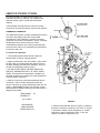
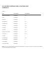
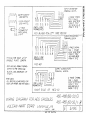
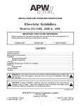
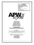
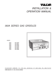
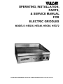
OPERATING, INSTALLATION,
PARTS,
& SERVICE MANUAL
FOR
ELECTRIC GRIDDLES
MODELS: HEG36, HEG48, HEG60, HEG72
VULCAN-HART CORPORATION, P.O. BOX 696, LOUISVILLE, KENTUCKY 40201, TEL. (502) 778-2791
OPERATING, INSTALLATION AND SERVICE PERSONNEL
Operating information for this equipment has been prepared for use by qualified and/or authorized operating
personnel
All installation and service on this equipment is to be performed by qualified, certified, licensed and/or
authorized installation or service personnel, with the exception of any marked with a a in front of the part
number
Service may be obtained by contacting the Factory Service Department, Factory Representative or Local
Service Agency
DEFINITIONS
QUALIFIED AND/OR AUTHORIZED OPERATING PERSONNEL
Qualified or authorized operating personnel are those who have carefully read the information in this manual
and are familiar with the equipment's functions or have had previous experience with the operation of the
equipment covered in this manual
QUALIFIED INSTALLATION PERSONNEL
Qualified installation personnel are individuals, a firm, corporation or company which either in person or
through a representative are engaged in, and are responsible for
1. The installation of gas piping from the outlet side of the gas meter, or the service regulator when the meter
is not provided, and the connection and installation of the gas appliance Qualified installation personnel
must be experienced in such work, be familiar with all precautions required, and have complied with all
requirements of state or local authorities having jurisdiction Reference in the United States of America National Fuel Gas code ANSI Z223 1 (Latest Edition) In Canada-Canadian Standard CAN1-B149 1 NAT
GAS (Latest Edition) or CAN1-B149 2 PROPANE (Latest Edition)
2. The installation of electrical wiring from the electric meter, main control box or service outlet to the electric
appliance Qualified installation personnel must be experienced in such work, be familiar with all
precautions required, and have complied with all requirements of state or local authorities having
jurisdiction Reference In the United States of America-National Electrical Code ANSI NFPA No 70 (Latest
Edition) In Canada-Canadian Electrical Code Part 1 CSA-C22 1 (Latest Edition)
QUALIFIED SERVICE PERSONNEL
Qualified service personnel are those who are familiar with Vulcan equipment who have been endorsed by
the Vulcan-Hart Corporation All authorized service personnel are required to be equipped with a complete set
of service parts manuals and stock a minimum amount of parts for Vulcan equipment
SHIPPING DAMAGE CLAIM PROCEDURE
For your protection, please note that equipment in this shipment was carefully inspected and packed by
skilled personnel before leaving the factory The transportation company assumes full responsibility for safe
delivery upon acceptance of this shipment
If shipment arrives damaged:
1. VISIBLE LOSS OR DAMAGE — Be certain this is noted on freight bill or express receipt and signed by
person making delivery
2. FILE CLAIM FOR DAMAGES IMMEDIATELY — Regardless of extent of damage
3. CONCEALED LOSS OR DAMAGE — If damage is unnoticed until merchandise is unpacked, notify
transportation company or carrier immediately, and file "concealed damage" claim with them This should
be done within (15) days of date of delivery is made to you Be sure to retain container for inspection
We cannot assume responsibility for damage or loss incurred in transit We will, however, be glad to furnish
you with necessary documents to support your claim
PLEASE RETAIN THIS MANUAL FOR FUTURE REFERENCE
IMPORTANT NOTES FOR ALL VULCAN APPLIANCES
1. These units are produced with the best possible workmanship and material Proper installation is vital if best performance and
appearance are to be achieved Installer must follow the installation instructions carefully.
2. Information on the construction and installation of ventilating hoods may be obtained from the Standard for the installation of
equipment for the removal of smoke and grease laden vapors from commercial cooking equipment NFPA No 96 (latest edition)
available from the National Fire Protection Association, Battery March Park Quincy MA 02269.
3. For an appliance equipped with a flexible electric supply cord, the cord is equipped with a three prong (grounding) plug This
grounding plug is for your protection against shock hazard and should be plugged directly into i proper1. grounded three prong
receptacle Do not cut or remove the grounding prong from this plug If the appiance0 is - * equipped with a grounding plug, and
electric supply is needed, ground the appliance by using the ground lug provided (refer to the wiring diagram).
(FOR GAS APPLIANCES ONLY)
4. Do not obstruct the air flow into and around the appliance This air flow is necessary for proper combustion of gases and for
ventilation of the appliance. Provisions for ventilation of incoming air supply for the equipment in the room must be in
accordance with National Fuel Gas Code ANSI Z223 1 (latest edition).
5. Do not obstruct the flow of flue gases from the flue duct (when so equipped) located on the rear (or sides) of the appliance It is
recommended that the flue gases be ventilated to the outside of the building through a ventilation system installed by qualified
personnel.
6. For an appliance equipped with casters, (1) the installation shall be made with a connector that complies with the Standard for
Connectors for Movable Gas Appliances, ANSI Z21 69 (latest edition), and Addenda, Z21 69a (latest edition), and a quickdisconnect device that complies with the Standard for Quick-Disconnect Devices for Use With Gas Fuel, ANSI Z21 41 (latest
edition), and Addenda, Z21 41 a (latest edition) and Z21 41 b (latest edition) and (2) adequate means must be provided to limit
the movement of the appliance without depending on the connector and the quick-disconnect device or its associated piping to
limit the appliance movement If disconnection of the restraint is necessary, reconnect this restraint after the appliance has been
returned to its originally installed position.
7. The appliance and its individual shutoff valve must be disconnected from the gas supply piping system during any pressure
testing of that system at test pressures in excess of 1/2 psig (3 45 k Pa).
8. The appliance must be isolated from the gas supply system by closing i ts individual manual shutoff valve during any pressure
testing of the gas supply system at test pressures equal to or less than \1/2 psig (3 45 k Pa).
CAUTIONS
FOR YOUR SAFETY
DO NOT STORE OR USE GASOLINE OR OTHER FLAMMABLE VAPORS AND LIQUIDS
IN THE VICINITY OF THIS EQUIPMENT OR ANY OTHER APPLIANCE.
1. KEEP THE APPLIANCE FREE AND CLEAR FROM ALL COMBUSTIBLE SUBSTANCES.
2. IN THE EVENT A GAS ODOR IS DETECTED, SHUT UNIT(S) DOWN AT THE MAIN
SHUTOFF VALVE AND CONTACT THE LOCAL GAS COMPANY OR GAS SUPPLIER
FOR SERVICE.
3. POST IN A PROMINENT LOCATION, INSTRUCTIONS TO BE FOLLOWED IN THE EVENT
THE SMELL OF GAS IS DETECTED. THIS INFORMATION MAY BE OBTAINED FROM A
LOCAL GAS SUPPLIER.
HEAVY DUTY ELECTRIC GRIDDLES: OPERATING INSTALLATION,
SERVICE AND PARTS MANUAL INDEX
Your Heavy Duty Electric Griddle is produced with the
best possible workmanship and material. Proper usage
and maintenance will restult in many years of satisfactory
performance.
The manufacturer suggests that you thoroughly read this
entire manual and carefully follow all of the instructions
provided.
Vulcan Griddles are constructed and designed to give
long satisfactory service, providing they are properly
installed and adjusted, and given reasonable care.
To establish terminology which will be understood, the
following lists the names of some of the parts of the
griddle.
INDEX
PAGE
DEFINITIONS OF PERSONNEL (Installation, Service & Parts)
and SHIPPING DAMAGE CLAIM PROCEDURES
(Inside Front Cover)
CAUTION NOTES
1
INDEX
2
POWER SUPPLY CONNECTION
3
OPERATING INSTRUCTIONS
4
SERVICE INSTRUCTIONS
5-6
SUGGESTED TEMPERATURES AND TIMES FOR GRIDDLING - TABLE 1
7
GRIDDLING TROUBLE SHOOTING GUIDE-TABLE 2
8
MAINTENANCE TROUBLE SHOOTING GUIDE
9
REPLACEMENT PARTS LIST
10
WIRING DIAGRAMS
11-12
REVISION PAGE
(Inside Back Cover)
2
INSTALLATION
1. Carefully uncrate the unit.
3. Level the griddle plate using leveling legs.
2. The griddle is shipped as a complete unit, and does not
require field assembly except the supporting legs. Bolt the legs
on four corners of the unit.
CAUTION: Do not slide unit with legs mounted. If it is
necessary to move the unit, it should be lifted.
POWER SUPPLY CONNECTION
1. All units are provided with a terminal block for field wire
connections behind the circuit breaker cover. A knockout
hole is provided for a 1" conduit connection. Two
knockout holes provided on the H EG 60 & 72.
5. After making the connections, replace the circuit
breaker cover plate.
2. Remove the circuit breaker cover plate. Mount a
suitable 1" conduit fitting in knockout opening.
(a) Installing personnel should be guided by the National
Electrical Code NFPA No. 96-1981. and applicable local
codes.
3. Connect field wiring to the terminal block as indicated
on wiring diagram. Wire must be the type suitable for
90°C. service, and sized as indicated on the marking next
to junction box.
6. The following precautions must be observed:
(b) The equipment must be grounded, by installing a
grounding lead to the ground lug located inside the circuit
breaker compartment.
4. For convenience in testing, the rated amperages are
listed below.
STANDARD VOLTAGES—208 VOLTS OR 240 VOLTS 60 Hz.—SINGLE PHASE OR THREE PHASE
OPTIONAL VOLTAGE—480 VOLTS 60 Hz.—THREE PHASE ONLY
TOTAL
3 PHASE LOADING
NOMINAL
AMPS PER LINE WIRE PER CONNECTION'
TOTAL
KW
UNIT
CONN.
PER
KW
CONN.*
X-Y
Y-Z
X-Z
X
Y
Z
X
Y
Z
X
V
HEG36
16.8
16.8
5.6
5.6
5.6
46
46
46
40
40
40
20
20
HEG48
22.4
22.4
5.6
56
11.2
70
47
70
61
40
61
30
20
HEG60*
28.0
16.8
5.6
5.6
5.6
46
46
46
40
40
40
20
11.2
5.6
5.6
0.0
21
47
21
18
40
18
16.8
5.6
5.6
5.6
46
46
46
40
40
16.8
5.6
5.6
5.6
46
46
46
40
40
HEG72"
33.6
KW PER PHASE
3 PHASE
PER CONN.*
208 VOLT
240 VOLT
*Model HEG 60 & 72 Require Two (2) Separate Electrical Connections and Services.
NOTE: These values are nominal ratings. Field wire
connections must be capable of withstanding anticipated surges.
480
1 PHASE
VOLT
208
240
Z
Volt
VOL"
20
81
70
30
108
93
20
20
81
70
9
20
9
54
47
40
20
20
20
81
70
40
20
20
20
81
70
OPERATING INSTRUCTIONS
Cleaning the Griddle at Start Up
1. The griddle is shipped covered with a protective coating of oil.
Remove this film only when the griddle plate is being cleaned
prior to its first cooking use. If the griddle is to be shut down for
an extended period put a heavy coat of grease or oil over the
griddle plate.
CAUTION: Care must be exercised not to overheat the griddle
plate by setting the thermostats well above recommended
temperatures. Overheating the plate may cause plate warpage,
and will carbonize any grease on the plate and cause sticking.
2. Seasoning the Griddle Plate A new griddle surface must be
seasoned to do a good job. The metal surface of the griddle is
porous. Food tends to get trapped in these pores and stick;
'therefore, it is important to "season" or "fill up" these pores with
griddling fat before cooking on any metal surfaced griddle.
Seasoning gives the surface a slick, hard finish from which the
food will release easily.
To season, heat the griddle to a low temperature and pour, a
small amount of cooking oil on it, about one ounce per square
foot of surface. Spread the oil over the entire griddle surface
with a cloth to create a thin film. Wipe off any excess oil with a
cloth. Griddle should also be seasoned afte r each cleaning.
3. NOTE: For each 12" length of griddle plate the unit has one
set of heating elements, a thermostat and a two pole *circuit
breaker with completely separate wiring to the terminal block
where the service connection is made. Access to the *circuit
breaker on-off levers is gained by opening the hinged cover to
the left (or to left and right of units five feet long or longer). Turn
all the circuit breakers on, should one open by its own action,
there is something wrong with this section and service is
needed. Other sections may be used until the needed service
can be rendered.
*Two-pole circuit breakers used on 208-240 volt units only.
4. To use, turn the thermostat for one or more sections
(according to load requirements) to the desired te mperature 10
to 15 minutes before grilling is to start. Amber signal light (visible
through the slotted opening at top of the thermostat dial bezel
plate) will glow only as long as thermostat calls for heat. When
the light cycles off the temperature of the griddle surface has
reached the thermostat setting.
5. CAUTION: This griddle plate is steel, but the surface is
relatively soft and can be scored or dented by carelessly using a
spatula. Be careful not to dent, scratch, or gouge the plate
surface. Do not try to knock off loose food that may be on the
spatula by tapping the corner or the edge of the spatula on the
griddle surface.
6. Cleaning
Empty the grease drawer daily or more often as needed. Clean
the unit regularly. A clean unit looks better, lasts longer, and
performs better.
Keep the griddle plate surface clean to produce evenly cooked,
perfectly browned griddle products keep the griddle free from
carbonized grease Car bonized grease on the surface hinders
the transfer of heat from the griddle surface to the food. This
results in spotty browning and loss of cooking effi ciency and,
worst of all. carbonized grease tends to cling to griddled foods,
giving them a highly unsatisfactory and unappetizing
appearance. To keep the griddle clean and operating at peak
efficiency, follow these instructions:
(a) AFTER EACH USE: Clean griddle with a flexible spatula or
griddle scraper.
(b) DURING THE DAY: Flush the hot griddle with water and
scrape with a griddle scraper to reduce the amount of
carbonized grease buildup, follow with a light coating of oil to
prevent product sticking.
(c) ONCE A DAY: Thoroughly clean the splash back, sides and
front. Remove the grease pan, empty and wash out in the same
manner as any ordinary cooking utensil.
Clean griddle surface thoroughly with water and degreasing
cleaner. Rub with grain of the metal while still warm. Care must
be taken to be sure the degreasing cleaner is thoroughly
removed by flushing with clear water. After removal of the
detergent, the surface of the plate should be reseasoned as
covered in item 2 above. Clean stainless steel or chromed
surfaces with a damp cloth and polish with a soft dry cloth. To
remove discolorations, use a non-abrasive cleaner.
7. For additional hints on griddle cooking and operation, refer to
Tables 1, pg. 7 and 2, pg. 8 )
4
SERVICE INSTRUCTIONS
Any electric griddle, no matter how well made, will
eventually need service attention. The equipment will
need less service if given normal care and frequent
cleaning.
Vulcan griddles are engineered to make service easy.
Any part can be easily and quickly removed and replaced.
THERMOSTAT CALIBRATION
The griddle thermostat is carefully calibrated at the factory
so that the dial settings match the actual griddle
temperatures. Field recalibration is seldom necessary,
unless the unit has been mishandled in transit, or abused.
Recalibration should not be resorted to unless
coinsiderable experience with cooking results definitely
proves that the control is not maintaining the temperature
to which the dial is set.
To Check The Calibration
1. Use a griddle type test instrument and place the
thermocouple on section of griddle desired.
2. With thermostat dial in the OFF position, make certain
the OFF mark on the dial agrees with reference point of
the bezel. Misalignment will affect calibration. Then turn
the dial to a temperature setting of 375°F.
3. ALLOW TO HEAT UNTIL CONTROL SNAPS "ON
AND OFF" THERMOSTATICALLY AT LEAST THREE
TIMES. This will allow the temperature to stabilize and
eleminate possible error resulting from initial temperature
overshoot and/or undershoot.
4. After the control has cycled thermostatically three or
more times, note the surface temperature when the
electric units snap off, and the temperature when the unit
snaps on. RECALIBRATE ONLY if the average of these
two temperature readings varies more than the number of
degrees shown below.
TEMP.RANGE
DEGREES F.
IN
150° to 450°F.
FIGURE 1
RECALIBRATE
WHEN OUTSIDE
THESE LIMITS ±10°
5. Hold the thermostat dial shaft "B" (Figure 1) stationary
with pliers, and with a screwdriver, turn screw "A" (Figure
1) clockwise to obtain a lower temperature; or counterclockwise for higher temperature. Each 1/4 turn (90°
rotation of screw "A" represents 18°F.)
SERVICE INSTRUCTIONS (Continued)
REPLACEMENT OF COMPONENTS
NOTE: All of the following service procedures involve exposing
or handling normally live wires. The unit must be disconnected
from the power source.
There are three areas in which service may be necessary.
They are:
I. Plate Assembly Contains:
Elements Thermostat
Bulb Wiring
II. Circuit Breaker Compartment Contains:
Circuit Breakers
Terminal Block Wiring
Compartment
III. Thermostat Panel Contains:
Thermostats Wiring
I. Plate Assembly (Removing or Replacing Element or
Thermostat Bulb).
A. Remove the plate. The hold down clip is located under the
front band, raise the front edge of the plate assembly up and
prop with chock angles located at each front corner of the
griddle body.
B. Remove the element cover and insulation secured by four
screws (two front edge, two rear edge).
1. Remove the element(s) (inner or outer):
a. Disconnect the leads to the element(s). b. Remove
element clips. c. Remove element.
2. Remove the thermostat bulb:
a. Remove the three nuts securing the bulb shields. b.
Remove the bulb shields.
II. Circuit Breaker Compartment
A. To reset the circuit breaker (208-240V units) open the door
and reset it.
B. To gain access to this area open the circuit breaker hinged
cover and remove panel thus exposed.
C. To replace a circuit breaker:
1. Remove the wires from that breaker only.
2. Loosen two screws on the breaker top clamp bar, pull the
top of the breaker forward to clear the upper clamp bar and
raise the breaker to clear the lower clamp bar.
III. Thermostat Panel.
A. Remove the panel by removing one screw at each
end of the panel.
1. Remove the thermostat:
a. Remove the knob (pull it off).
b. Remove the thermostat retaining screws (two) one
each side of the stem.
c. Remove the leads from thermostat.
d. Remove the capillary tube from the plate assembiy as
outlined in 1 above.
SUGGESTED TEMPERATURES AND TIMES FOR
GRIDDLING
TABLE—1
Food
Control Setting
Time in Minutes
American Fried Potatoes
375 Degrees
3 to 4
Bacon
350 Degrees
6
Boiled Ham
375 Degrees
2
Beef Tenderloin
400 Degrees
5 to 7
Canadian Bacon
350 Degrees
3 to 4
Hamburgers
350 Degrees
3 to 4
Club Steak
450 Degrees
3 to 5
Ham Steak
400 Degrees
10
Sausage Links or Patties
350 Degrees
3 to 4
French Toast
400 Degrees
4 to 5
Pancakes
375 Degrees
2
Scrambled Eggs
300 Degrees
3 to 4
Hard Fried Eggs
300 Degrees
3
Soft Fried Eggs
300 Degrees
2
Sunny Side Up Eggs
300 Degrees
3
NOTE: These are only suggested griddle temperatures and cooking times. You may want to try others. For example, some restaurants
are cooking hamburgers at 300°F and under.
GRIDDLING TROUBLE SHOOTING GUIDE
TABLE — 2
MAINTENANCE TROUBLE SHOOTING GUIDE
PROBLEM
POSSIBLE CAUSE
1. Amber light on all thermostats fails to light
1. Not plugged in
when thermostats are turned on.
2. Store circuit breaker tripped.
3. All unit circuit breakers off*.
2. Amber light on one thermostat fails to light
1. Thermostat bad
when thermostat is turned on.
2. Light bad
3. Unit circuit breaker* tripped.
3. Amber light lit but
1. Thermostat bad
one section of griddle not heating.
2. Heating element bad.
3. Loose or broken wiring to heating element
4. Circuit breaker will not stay on.
1. Short circuit
2. Circuit breaker bad*
3. Heating element bad
4. Improper voltage
*Two pole circuit breakers used on 208-240 volt units only.
REPLACEMENT PARTS LIST
Quantity
Part No.
Part Name
1 or 2
6821-001
Grease Pan Body
1 or 2
6822
Grease Pan Front
1 or 2
20180
Grease Pan Handle w/screws
1 per foot
4654-11
Outer Element - 208 Volts
1 per foot
4654-12
Outer Element - 236 Volts
1 per foot
4654-13
Outer Element - 480 Volts
1 per foot
4655-11
Inner Element - 208 Volts
1 per foot
4655-12
Inner Element - 236 Volts
1 per foot
4655-13
Inner Element - 480 Volts
1 per foot
4746
Thermostat
1 per foot
4747
Circuit Breaker Heinemann 2912 30 Amp
1 or 2
5726
Terminal Block
2 or 4
4748
Breaker Mounting Clamp
1
6824-001
Breaker Door Assembly HEG-36 & HEG-72 LH
2 or 4
6802
Hinge Leaf
1 or 2
81761
Door Magnet
1
6824-002
Breaker Door Assembly HEG-48
1
6824-003
Breaker Door Assembly HEG-60 LH
1
6824-004
Breaker Door Assembly HEG-60 RH
1
6824-005
Breaker Door Assembly HEG-72 RH
1
4812-001
Griddle Plate Assy HEG-36
1
4813-001
Griddle Plate Assy HEG-48
1
4814-001
Griddle Plate Assy HEG-60
1
4815-001
Griddle Plate Assy HEG-72
NOTE: Order just the quantity of parts that need to be replaced.
MANUAL PART NO.: 99-04-05A
FOR MODELS: HEG 36, HEG 48 HEG 60,
HEG 72, ELECTRIC
GRIDDLES
DESCRIPTION:
OPERATING, INSTALLATION, SERVICE
AND PARTS MANUAL
REV. BLOCK
REV.#
1
DATE
3/84
SIG.
DH