1
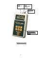
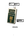
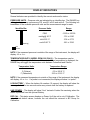
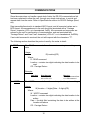
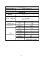
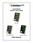
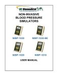
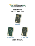
DIGITAL PRESSURE METERS
DPM-2001
DPM-2001PLUS
DPM-2100
USER MANUAL
BC BIOMEDICAL
DPM-2000 SERIES
TABLE OF CONTENTS
WARNINGS, CAUTIONS, NOTICES ............................................................................. ii
DESCRIPTION ............................................................................................................... 1
LAYOUT ......................................................................................................................... 2
DISPLAY INDICATORS ................................................................................................ 5
KEYS ............................................................................................................................. 6
SETUP MODE ............................................................................................................... 9
COMMUNICATIONS .................................................................................................... 10
MANUAL REVISIONS .................................................................................................. 13
LIMITED WARRANTY ................................................................................................. 13
SPECIFICATIONS ....................................................................................................... 14
NOTES ......................................................................................................................... 16
i
WARNING - USERS
The DPM-2000 Series is for use by skilled
technical personnel only.
WARNING - USE
The DPM-2000 Series is intended for testing only
and should never be used in diagnostics,
treatment or any other capacity where it would
come in contact with a patient.
WARNING - CONNECTIONS
All connections to patients must be removed
before connecting the DUT to the DPM-2000
Series. A serious hazard may occur if the patient
is connected when testing with the DPM-2000
Series. Do not connect anything from the patient
directly to the DPM-2000 Series or DUT.
WARNING - MODIFICATIONS
The DPM-2000 Series is intended for use within
the published specifications. Any application
beyond these specifications or any unauthorized
user modifications may result in hazards or
improper operation.
CAUTION - INSPECTION
The DPM-2000 Series should be inspected before
each use for wear and should be serviced if any
parts are in question.
CAUTION – MEDIA COMPATIBILITY
The DPM-2000 Series is intended to be used with
only non-corrosive, non-ionic, or otherwise pure
fluids and/or gases that are compatible with
sensor materials including glass, silicon,
ceramic, epoxy, RTV, gold, aluminum and nickel.
ii
CAUTION - SERVICE
The DPM-2000 Series is intended to be serviced
only by authorized service personnel.
Troubleshooting and service procedures should
only be performed by qualified technical
personnel.
CAUTION - ENVIRONMENT
Exposure to environmental conditions outside
the specifications can adversely affect the
performance of the DPM-2000 Series. Allow the
DPM-2000 Series to acclimate to specified
conditions for at least 30 minutes before
attempting to operate it.
CAUTION - CLEANING
Do not immerse. The DPM-2000 Series should be
cleaned by wiping gently with a damp, lint-free
cloth. A mild detergent can be used if desired.
iii
NOTICE – SYMBOLS
Symbol Description
Center Negative
NOTICE – ABBREVIATIONS
ANSI
American National Standards Institute
BCD
Binary Coded Decimal
C
cmH20
°
DUT
DC
Celsius
Centimeter(s) water
Degree(s)
Device Under Test
Direct Current
Euro
European
F
Fahrenheit
FS
Full Scale
inH20
Inche(s) of water
kg
kilogram(s)
µA
microampere(s)
mA
milliampere(s)
mBar
mm
milliBar(s)
millimeter(s)
mmHg
millimeter(s) of Mercury
NEDA
National Electronic Distributors Association
Lbs
pounds
PSI
pounds per square inch
USA
United States of America
VDC
Volts Direct Current
iv
NOTICE – DISCLAIMER
BC GROUP INTERNATIONAL, INC. WILL NOT BE RESPONSIBLE
FOR ANY INJURIES SUSTAINED DUE TO UNAUTHORIZED
EQUIPMENT MODIFICATIONS OR APPLICATION OF EQUIPMENT
OUTSIDE OF THE PUBLISHED INTENDED USE AND
SPECIFICATIONS.
NOTICE – DISCLAIMER
BC GROUP INTERNATIONAL, INC. RESERVES THE RIGHT TO
MAKE CHANGES TO ITS PRODUCTS OR SPECIFICATIONS AT
ANY TIME, WITHOUT NOTICE, IN ORDER TO IMPROVE THE
DESIGN OR PERFORMANCE AND TO SUPPLY THE BEST
POSSIBLE PRODUCT. THE INFORMATION IN THIS MANUAL HAS
BEEN CAREFULLY CHECKED AND IS BELIEVED TO BE
ACCURATE. HOWEVER, NO RESPONSIBILITY IS ASSUMED FOR
INACCURACIES.
NOTICE – CONTACT INFORMATION
BC BIOMEDICAL
BC GROUP INTERNATIONAL, INC.
3081 ELM POINT INDUSTRIAL DRIVE
ST. CHARLES, MO 63301
USA
1-800-242-8428
1-314-638-3800
www.bcgroupintl.com
[email protected]
DPM-2000 Series User Manual
www.bcgroupintl.com
08/12
Copyright © 2012
Made in the USA
Rev 09
v
This Page Intentionally Left Blank
vi
BC BIOMEDICAL
DPM-2000 SERIES
DIGITAL PRESSURE METERS
The Model DPM-2000 Series is a Microprocessor based Digital Pressure Meter family.
They measure both gas and liquid pressures and provide multiple engineering unit
displays for the results. The following are highlights of some of the main features.
DPM-2001:
-13.50 TO 100.00 PSI RANGE
PRESSURE SCALES INCLUDE PSI, inH2O, cmH2O, AND mmHg
DIGITAL CALIBRATION – NO POTS TO TURN
5 DIGIT LCD PLUS SCALE INDICATION
BATTERY LIFE DISPLAY (0 to 100%)
PROGRAMMABLE DIGITAL FILTER
LCD CONTRAST IS SOFTWARE ADJUSTABLE
16 BIT PRESSURE MEASUREMENT
DIGITAL ZERO ADJUST
DPM-2001PLUS:
Includes all the features of the DPM-2001 and:
MAX and MIN PRESSURE VALUE STORAGE
RS232 SERIAL COMMUNICATIONS
DPM-2100:
Includes all the features of the DPM-2001PLUS and:
YSI 700 TEMPERATURE PROBE INTERFACE
0.0 TO 100.0 °C (32.0 TO 212.0 °F) TEMPERATURE RANGE
MAX and MIN TEMPERATURE VALUE STORAGE
OPTIONAL ACCESSORIES:
BC20-21100
BATTERY ELIMINATOR (USA VERSION)
BC20-21101
BATTERY ELIMINATOR (EURO VERSION)
BC20-21102
RS-232 COMMUNICATIONS CABLE (1/8
STEREO PLUG TO DB-9F)
BC20-41339
USB COMMUNICATIONS ADAPTER (DB-9M to
USB-A)
BC20-30106
SOFT-SIDED CARRYING CASE
BC20-01005
UNIVERSAL PRESSURE ADAPTER KIT
BC20-01006
YSI 700 TEMPERATURE PROBE
1
LAYOUT
This section looks at the layout of the DPM-2000 series and gives descriptions of the
elements that are present.
Temperature:
¼” Phone Jack
RS-232:
⅛” Stereo Jack
Power:
2.1 mm receptacle
(Optional Battery
Eliminator)
Pressure Port:
Male Luer Lock
Coupler
6 Light Touch Keys for
Selecting Parameters and
Settings
DPM-2100 Layout
2
RS-232:
⅛” Stereo Jack
Power:
2.1 mm receptacle
(Optional Battery
Eliminator)
Pressure Port:
Male Luer Lock
Coupler
6 Light Touch Keys for
Selecting Parameters and
Settings
DPM-2001PLUS LAYOUT
3
Power:
2.1 mm receptacle
(Optional Battery
Eliminator)
Pressure Port:
Male Luer Lock
Coupler
4 Light Touch Keys for
Selecting Parameters and
Settings
DPM-2001 LAYOUT
4
DISPLAY INDICATORS
Several indicators are provided to identify the current mode and/or status.
PRESSURE UNITS – Pressure units are indicated by an identifier bar. The RANGE key
will toggle the pressure units among PSI, mmHG, inH2O and cmH2O. The following is a
breakdown of the available pressure units and the measurement range for each:
Identifier Bar
(flashing)
Pressure Units
Range
PSIG
-13.50 to 100.00
mmHg @ 20 °C
-701 to 5190
inH2O 20 °C
-374 to 2773
cmH2O 20 °C
-951 to 7043
bar
no bar
NOTE: If the measured pressure is outside of the range of the instrument, the display will
display -HI- or -Lo-.
TEMPERATURE UNITS (MODEL DPM-2100 ONLY) – The temperature can be
displayed in either degrees Celsius or Fahrenheit. When temperature is displayed, the
RANGE key will toggle the temperature units between Fahrenheit and Celsius.
Temperature Units
Temperature Range
C (Celsius)
F (Fahrenheit)
0.0 to 100.0 °C
32.0 to 212.0 °F
NOTE: If the measured temperature is outside of the range of the instrument, the display
will display -HI- or -Lo-. If a probe is not connected, the display will show “no probe”.
LOW BATTERY – When the battery life reaches 10 percent, the display will show the
message “lo bat” for two seconds once every minute until the battery is replaced.
LINE POWER – The display will show “Line” instead of batter life remaining when the
meter is powered from the optional Battery.
DEF CAL – This status screen displays on Power Up if the unit is out of Calibration. The
unit will load default values, however the unit should be returned to BC Group for
Calibration.
5
KEYS
Several tactile-touch keys are provided for system operation.
– The function of this key is dependant on the Current Operating Mode as follows:
POWER OFF – If this key is pressed while the power is turned OFF, the power will
be turned ON
PRESSURE MEASUREMENT – If this key is pressed while the pressure is being
displayed, the Setup Mode will be entered.
TEMPERATURE MEASUREMENT (DPM-2100) – If this key is pressed while the
temperature is being displayed, the Setup Mode will be entered.
SETUP MODE – Pressing this key while in the Setup Mode will sequence the
display through the available parameters.
– The function of this key is dependent on the Current Operating Mode as follows:
PRESSURE MEASUREMENT – If this key is pressed while the pressure is being
displayed, the power will be turned OFF
TEMPERATURE MEASUREMENT (DPM-2100) – If this key is pressed while the
temperature is being displayed, the power will be turned OFF
SETUP MODE – Pressing this key while in the Setup Mode will exit the Setup Mode
and automatically save all settings.
MIN/MAX MODE (DPM-2001PLUS & DPM-2100) – Pressing this key when a MIN
or MAX Value is being displayed (MIN or MAX key is held down) will cause
that value in that capture register to be reset to the current reading.
6
(DPM-2001) or
(DPM-2001PLUS & DPM-2100) – The function of this key is
dependant on the Current Operating Mode as follows:
PRESSURE MEASUREMENT (DPM-2001) – If this key is pressed while the
pressure is being displayed, the unit will step through the available pressure
ranges (PSI, inH20, cmH20 and mmHg).
PRESSURE MEASUREMENT (DPM-2001PLUS & DPM-2100) – If this key is
pressed while the pressure is being displayed, the unit will display the
maximum pressure detected since the capture register was last reset.
TEMPERATURE MEASUREMENT (DPM-2100) – If this key is pressed while the
temperature is being displayed, the unit will display the maximum
temperature detected since the capture register was last reset.
SETUP MODE – If this key is pressed in the Setup Mode, the value of the displayed
setting will increment. Pressing and holding this key will cause the rapid
automatic incrementing of the displayed setting.
(DPM-2001) or
(DPM-2001PLUS & DPM-2100) – The function of this key is
dependant on the Current Operating Mode as follows:
PRESSURE MEASUREMENT (DPM-2001) – If this key is pressed while the
pressure is being displayed, the unit will display the percent (0 to 100) of
battery life remaining.
PRESSURE MEASUREMENT (DPM-2001PLUS & DPM-2100) – If this key is
pressed while the pressure is being displayed, the unit will display the
minimum pressure detected since the capture register was last reset.
TEMPERATURE MEASUREMENT (DPM-2100) – If this key is pressed while the
temperature is being displayed, the unit will display the minimum
temperature detected since the capture register was last reset.
SETUP MODE – If this key is pressed in the Setup Mode, the value of the displayed
setting will decrement. Pressing and holding this key will cause the rapid
automatic decrementing of the displayed setting.
7
ZERO – This function is a combination of two keys:
DPM-2001:
DPM-2001PLUS & DPM-2100:
If both keys are depressed and held for 5 seconds, the pressure display will be zeroed.
(DPM-2001PLUS & DPM-2100) – The function of this key is to select the desired
display engineering units. When viewing pressure it will sequence through the four
pressure ranges (PSI, inH20, cmH20 and mmHg). When viewing temperature (DPM-2100),
it will toggle between Celsius and Fahrenheit.
(DPM-2001PLUS) - If this key is pressed while the pressure is being displayed, the
unit will display the percent (0 to 100) of battery life remaining.
(DPM-2100) – The function of this key is to toggle between pressure and
temperature displays.
8
SETUP MODE
The Setup Mode allows the user to adjust the configuration of the meter. The Setup Mode
is entered by pressing The ON/SETUP key when the unit is on. The parameter and the
current value will alternately flash in the display. The following table indicates the
Parameters that are available, their meaning and available setting range:
PARAMETER
DESCRIPTION
RANGE
BAT
REMAINING BATTERY LIFE
0 - 100 % (READ ONLY)
CONT
CONTRAST
0 - 15
AOFF
AUTO OFF TIMER
0 - 30 MINUTES
BEEP
KEY BEEP LENGTH
0 - 15
FCON
DIGITAL FILTER CONSTANT
1 - 255
BAT – (DPM-2100 ONLY) This parameter gives an estimated indication of the remaining
battery life displayed as a percentile.
CONT – This parameter controls the contrast of the LCD display. A Higher setting will
cause the display to darken. A lower setting will cause the display to lighten.
AOFF – This parameter determines the period of user inactivity before the meter is
automatically turned OFF. A timer is started when the meter is turned ON and is reset each
time a key is pressed. When the timer reaches the value set in this parameter, the meter is
automatically turned OFF.
NOTE: Setting this parameter to 0 disables the Auto Off feature.
NOTE: The meter will not automatically turn off when powered by the Battery
Eliminator, regardless of AOFF setting.
BEEP – This parameter controls the length of the audio feedback beep (click) that occurs
when a key is depressed. A Higher setting will cause a longer (louder) beep. If the value is
set to 0, the beep is eliminated.
FCON – This parameter controls the Filter Constant. The software has a Digital Filter that
averages the pressure readings to produce a stable display. This setting determines the
number of samples that are averaged in the digital filter. Increasing this setting will cause a
more stable display. However, it will also cause a slower response to small changes in
pressure. The best setting is the smallest number that provides a stable display.
9
COMMUNICATIONS
Since the meter does not handle a great deal of data, the RS-232 communications link
has been optimized to allow the user, through very simple instructions, to control and
request data from the meter. Refer to Specifications section for RS-232 Settings (Baud,
etc).
Data transmitted/received is in standard ASCII format, and all numerical values are in
BCD format. All commands sent to the unit should be terminated with a “Carriage
Return” character (<CR> or in hexadecimal, 0x0D). All commands and responses are
echoed by the unit for confirmation of communication, and are terminated with
“Carriage Return” and “Line Feed” characters (<CR><LF> or in hexadecimal, 0x0D0A).
If an invalid command is received, the unit will respond with the characters “??”.
The following section describes the protocol used by the meter in detail:
R - READ
The READ command allows the user to read system settings and
data.
Usage:
R(Location)(CR)
Where:
R - READ command
Location - contains two digits indicating the data location to be
read
CR - Carriage Return
Example:
Data Sent
R11<CR>
W - WRITE
Data Returned
R11<CR><LF>
-0011<CR><LF>
Meaning
Echo of Command Sent
-0.11 PSI measured
The WRITE command allows the user to update the system settings.
Usage:
W(Location – 2 digits)(Data – 5 digits)(CR)
Where:
W - WRITE command
Location - contains two digits indicating the data location to be
written
Data – five-digit field containing the data to be written at the
Location set above
CR - Carriage Return
10
Examples:
Data Sent
W172<CR>
Data Returned
W172<CR><LF>
W1700002<CR> W1700002<CR><LF>
W01100<CR>
U - UPLOAD
W01100<CR><LF>
??<CR><LF>
Meaning
Echo of Command Sent
(Set Pressure units to “inH2O”)
Echo of Command Sent
(Set Pressure units to “inH2O”)
Echo of Command Sent
Invalid Command Response
(Location 01 is Read Only)
The UPLOAD command allows the user to read all of the selected
device data from locations 1 through 16 with a single command. The
data returned will be formatted as a single block per location
separated by a carriage return, line feed character sequence (CRLF
– equivalent to hexadecimal 0x0D0A). See the table below for details
on the data structure.
Usage:
U(CR)
Where:
U – UPLOAD command
CR - Carriage Return
Q - QUICKSEND QUICKSEND is a feature that allows the user to receive an
automatic update of all of the meter data without any further user
interaction. When the QUICKSEND command is received, the
feature is turned ON and the meter will automatically send all of the
device data every half second. The Quicksend feature is toggled ON
and OFF with the QUICKSEND command. See the table below for
details on the data structure.
Usage:
Q(CR)
Where:
Q – QUICKSEND command
CR - Carriage Return
V - VERSION
The VERSION command allows the user to read the Software Version
that the unit is currently running.
Usage:
V(CR)
Where:
V – VERSION command
CR - Carriage Return
11
The CANCEL command is simply a way to re-establish proper control,
should a communications error occur or an incorrect command be
transmitted. For the most part, an incorrect command will simply be
ignored and the meter will return to listening for future commands.
However, a prior command may be cancelled midstream by transmitting
the CANCEL command anytime.
X - CANCEL
Usage:
X
This command does not require a carriage return, nor will it
acknowledge with a carriage return. However, it will echo an ‘X’
character to indicate that the CANCEL command has been received.
NOTE: The VERSION or CANCEL commands may also be utilized as
an acknowledgement of the meter being on line.
LOCATION
ACCESS
DESCRIPTION
RANGE
01
R
02
R/W
% BATTERY LIFE
REMAINING
CONTRAST
03
R/W
AUTO POWER OFF
0-30
08
R/W
FILTER CONSTANT
10
R
MODEL
11
R
PRESSURE
0-255
0 = DPM-2001
1 = DPM-2001+
2 = DPM-2100
See Note 1
12
R
MAX PRESSURE
See Note 1
13
R
MIN PRESSURE
See Note 1
14
R
TEMPERATURE
See Note 1
15
R
MAX TEMPERATURE
See Note 2
16
R
MIN TEMPERATURE
17
R/W
PRESSURE UNITS
18
R/W
TEMPERATURE UNITS
See Note 2
0=PSI
1=mmHg
2=inH2O
3=cmH20
0=Celsius
1=Fahrenheit
0-100
0-15
Note 1 – The units for the pressure data is determined by the setting in Location 17. This may be set via the
Write command or manually using the Range Key. See Specifications Page for Ranges.
Note 2 – The units for the temperature data is determined by the setting in Location 18. This may be set via
the Write command or manually using the Range Key. See Specifications Page for Ranges.
12
MANUAL REVISIONS
Revision #
Program #
Revisions Made
Rev 01
Rev 02
Rev 03
Rev 04
Rev 05
Rev 06
Rev 07
Rev 08
Rev 09
DT7325CA
DT7325CA
DT7325CA
DT7325CB
DT7325CD
DT7325CG
DT7325CG
DT7325CI
DT7325CI
Preliminary Manual
Misc. Edits
Battery Eliminator Updated
Status Display Graphics Updated
Accuracy Specifications Updated
Program Upgrades, Color Overlays Updated
Misc. Edits
Format Updated, Specifications Updated, Misc. Edits
Specifications Updated
LIMITED WARRANTY
WARRANTY: BC GROUP INTERNATIONAL, INC. WARRANTS ITS NEW PRODUCTS TO BE FREE
FROM DEFECTS IN MATERIALS AND WORKMANSHIP UNDER THE SERVICE FOR WHICH THEY
ARE INTENDED. THIS WARRANTY IS EFFECTIVE FOR TWELVE MONTHS FROM THE DATE OF
SHIPMENT.
EXCLUSIONS: THIS WARRANTY IS IN LIEU OF ANY OTHER WARRANTY EXPRESSED OR
IMPLIED, INCLUDING, BUT NOT LIMITED TO ANY IMPLIED WARRANTY OF MERCHANTABILITY
OR FITNESS FOR A PARTICULAR PURPOSE.
BC GROUP INTERNATIONAL, INC. IS NOT LIABLE FOR ANY INCIDENTAL OR CONSEQUENTIAL
DAMAGES.
NO PERSON OTHER THAN AN OFFICER IS AUTHORIZED TO GIVE ANY OTHER WARRANTY OR
ASSUME ANY LIABILITY.
REMEDIES: THE PURCHASER'S SOLE AND EXCLUSIVE REMEDY SHALL BE: (1) THE REPAIR OR
REPLACEMENT OF DEFECTIVE PARTS OR PRODUCTS, WITHOUT CHARGE. (2) AT THE OPTION
OF BC GROUP INTERNATIONAL, INC., THE REFUND OF THE PURCHASE PRICE.
P:\MANUALS\BCGroup\…\DPM-2000_UM_Rev09.doc
13
SPECIFICATIONS
PRESSURE
-13.50 to 100.00 PSI
-701 to 5190 mmHg @ 20 °C
-374 to 2773 inH2O @ 20 °C
-951 to 7043 cmH2O @ 20 °C
0.01 PSI
1 mmHg @ 20 °C
1 inH2O @ 20 °C
1 cmH2O @ 20 °C
RANGE
RESOLUTION
MAXIMUM
OVERPRESSURE
ACCURACY
± 0.1% FS
DIGITAL FILTER
1 – 255 samples
COMPATIBLE MEDIA
CONNECTIONS
200 PSI
Only non-corrosive, non-ionic, or otherwise pure fluids
and/or gases that are compatible with sensor materials
including glass, silicon, ceramic, epoxy, RTV, gold,
aluminum and nickel.
Male Luer Coupler
TEMPERATURE (DPM-2100 ONLY)
RANGE
0.0 to 100.0 °C (32.0 to 212.0 °F)
RESOLUTION
0.1 °C (0.1 °F)
ACCURACY
± 0.5% FS
CONNECTIONS
¼ inch Phone Jack for ¼ Phone Plug terminated
temperature cables or probes
SENSOR
COMPATIBILITY
YSI Series 700 Temperature Probes or equivalent
PHYSICAL
DISPLAY
CONSTRUCTION
MEMORY
5 Digit, 7-Segment Non-Backlit LCD
ENCLOSURE
ABS Plastic
OVERLAY
Lexan, Back Printed
SETUP
EEPROM, All Parameters
RETENTION
10 Years w/o Power
SIZE
7.69 x 3.97 x 1.82 Inches (195.3 x 100.8 x 46.2 mm)
WEIGHT
≤ 1 Lbs (0.45 kg)
14
ENVIRONMENTAL
OPERATING RANGE
0 to 50 °C (32 to 122 °F)
STORAGE RANGE
-40 to 60 °C (-40 to 140 °F)
ELECTRICAL
9V Alkaline
(ANSI/NEDA 1604A or equivalent)
BATTERY
9 V, 50 mA DC
BATTERY ELIMINATOR
POWER
CONSUMPTION
BATTERY LIFE
RS-232
COMMUNICATIONS
BC20-21100 (USA Version)
BC20-21101 (Euro Version)
ON
< 15 mA
OFF
< 40 A
CONTINUOUS
80 hours
OFF
1 year
BAUD
115200
DATA BITS
8
START BITS
1
STOP BITS
1
PARITY
none
HANDSHAKING
none
CONNECTIONS
1/8 Stereo Receptacle for use with
BC20-21102 RS-232 Cable
15
NOTES
16
NOTES
17
NOTES
18
BC GROUP INTERNATIONAL, INC.
3081 ELM POINT INDUSTRIAL DRIVE
ST. CHARLES, MO 63301
USA
1-800-242-8428
1-314-638-3800
www.bcgroupintl.com
[email protected]
DPM-2000 Series User Manual
08/12 – Rev 09
Copyright © 2012
Made in the USA