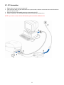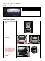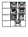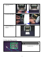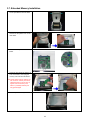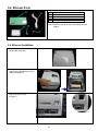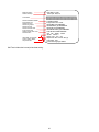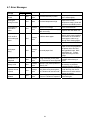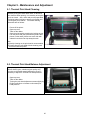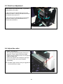
1
P/N. MD4206U-01 Edition 1 June 2004 Century Falcon 4D User Manual Table of Contents FCC COMPLIANCE STATEMENT FOR AMERICAN USERS This equipment has been tested and found to comply with the limits for a CLASS A digital device, pursuant to Part 15 of the FCC Rules. These limits are designed to provide reasonable protection against harmful interference when the equipment is operated in a commercial environment. This equipment generates, uses, and can radiate radio frequency energy and, if not installed and used in accordance with the instructions, may cause harmful interference to radio communications. Operation of this equipment in a residential area is likely to cause harmful interference in which case the user will be required to correct the interference at his/her own expense. EMS AND EMI COMPLIANCE STATEMENT FOR EUROPEAN USERS This equipment has been tested and passed with the requirements relating to electromagnetic compatibility based on the standards EN50081-1 (EN55022 CLASS A) and EN61000-4-2/-3/-4/-5/-6/-8/-11 (IEC Teil 2,3,4). The equipment also tested and passed in accordance with the European Standard EN55022 for the both Radiated and Conducted emissions limits. FALCON 4D Serial TO WHICH THIS DECLARATION RELATES IS IN CONFORMITY WITH THE FOLLOWING STANDARDS EN55022 : 1998,CLSPR 22 , Class A / EN55024 : 1998 IEC 61000-4 Serial / EN61000-3-2 : 2000 / EN 61000-3-3 : 1995 / CRF 47, Part 15/CISPR 22 3rd Edition : 1997,Class A / ANSI C63.4 : 2001 / CNS 13438,CISPR 22(Class A) / IEC60950 3rd Edition (1999) / GB4943 : 2001 / GB9254 : 1998 / GB17625.1 : 2003 CAUTION Danger of explosion if battery is incorrectly replaced Replace only with the equivalent type recommended by the manufacture. Dispose of used batteries according to the manufacturer’s instructions. Specifications are subject to change without notice. i WARRANTY INFORMATION .......................................................................................... II CHAPTER 1 – BARCODE PRINTER .............................................................................. 1 1-1 Introduction.......................................................................................................................... 1 1-2 Printer Models ..................................................................................................................... 1 1-3 Printer Accessories.............................................................................................................. 1 1-4 General Specifications......................................................................................................... 2 1-5 Communication Interface..................................................................................................... 3 1-6 Printer Parts......................................................................................................................... 4 CHAPTER 2 – PRINTER INSTALLATION ........................................................................ 5 2-1 Ribbon Installation ............................................................................................................... 5 2-2 Label Installation.................................................................................................................. 6 2-3 Label Roll Core Installation Instruction ................................................................................ 7 2-4 Card / Hang tags Installation ............................................................................................... 8 2-5 USB Installation ................................................................................................................... 8 2-6 USB Uninstallation............................................................................................................. 10 2-7 PC Connection .................................................................................................................. 11 CHAPTER 3 – OPTIONS INSTALLATION ..................................................................... 12 3-1 Stripper Parts..................................................................................................................... 12 3-2 Stripper Installation............................................................................................................ 12 3-3 Stripper Installation Diagram ............................................................................................. 14 3-4 Cutter Parts ....................................................................................................................... 15 3-5 Cutter Installation............................................................................................................... 15 3-6 Extended Memory Parts .................................................................................................... 17 3-7 Extended Memory Installation ........................................................................................... 18 3-8 Ethernet Parts.................................................................................................................... 19 3-9 Ethernet Installation........................................................................................................... 19 CHAPTER 4 – LED MESSAGE DESCRIPTION ............................................................. 21 4-1 LED Status ........................................................................................................................ 21 4-2 General Operation ............................................................................................................. 21 4-3 Self-Test ............................................................................................................................ 21 4-4 Dump Mode ....................................................................................................................... 23 4-5 Auto Sensing ..................................................................................................................... 23 4-6 Direct Thermal / Thermal Transfer Mode Switch............................................................... 23 4-7 Error Messages ................................................................................................................. 24 CHAPTER 5 – MAINTENANCE AND ADJUSTMENT ....................................................... 25 5-1 Thermal Print Head Cleaning ............................................................................................ 25 5-2 Thermal Print Head Balance Adjustment .......................................................................... 25 5-3 Print Line Adjustment ........................................................................................................ 26 5-4 Adjust the Cutter................................................................................................................ 26 5-5 Troubleshooting................................................................................................................. 27 ii Chapter 1 - Barcode Printer 1-1. Introduction The Century Systems FALCON 4D series is a desktop thermal transfer / direct thermal label printer. With plastic outer casing, the FALCON 4D series is designed to be a lightweight and a low cost printer for large variety of printing requirement. Its features are as follows: Direct Thermal and Thermal Transfer Printing Mode Print head density of 8 dots or 12dots per mm (203 or 300 dots per inch) Memory for label, graphics, and fonts download (approximately 100KB) Optional Real Time Clock for time recording and tracking Internal 5” (125mm) label roll capacity and 300M (Max O.D. 64mm) ribbon length (1” core size) Standard 2MB RAM for Maximum 68” print length Optional stripper module for label Optional cutter for ticketing or receipt printing applications Free Bundle of label editing software QLabel III 1-2. Printer Models CFD-4206 (203 DPI) CFD-4306 (300 DPI) 1-3. Printer Accessories After unpacking, please check the accessories that come with the package, and store them appropriately. Barcode Printer Power Cables (110V and 230V) Switching Power Adapter Parallel Port Cable Serial Port Cable (Optional) USB Cable Label Roll Core Ribbon Shaft (2pcs) Empty Roll Core Label Roll Sample Ribbon Roll Sample Quick Start Guide CD (including Software/Manual/Driver/DLL) Print Head Cleaning Card 15. Warranty Card / Warranty Information * If a different power supply is used with the printer which has caused damages to the printer itself, then this is not covered as part of the product warranty. 1 1-4. General Specifications Model Name Resolution Print Mode CPU Sensor Location Sensor Type Sensor Detection Print Speed Print Length Print Width Media Ribbon Printer Language Software Resident Fonts Fonts Download Image Handling Barcode Interface Interface Transmission Memory LED Display Power Environment Humidity Cert. Approval Printer Dimension Options CFD-4206 CFD-4306 203 dpi (8 dot/mm) 300 dpi (12 dot/mm) Thermal Transfer / Direct Thermal Thermal Transfer / Direct Thermal 16 Bit Moveable, center aligned Reflective Type: Label gap, black mark, and punch hole sensing. Detection: Label length auto sensing and / or program command setting 2~4 IPS Standard 2~3 IPS 5~6 IPS can be achieved (media dependant) Min. 12mm (0.47”); Max. 1727mm (68”) Min. 12mm (0.47”); Max. 762mm (30”) 104mm (4.10") 104mm (4.10") Label Roll OD: Max. 127mm (5”) Core Diameter: 1”, 1.5”, 3” Width: 25mm (1 “) ~ 118mm (4.65”) Thickness: 0.06~0.3mm (0.0025”~0.012”) Length: 300M (981 ft) Max. ribbon roll OD: 64mm (2.52 “) Type: transfer ribbons (wax, hybrid, and resin) in widths of 30mm to 110mm (1.88” to 4.33”) Core Inner Diameter: 25.4mm (1”) EZPL; Firmware Downloadable Application: QLabel-III DLL & Driver: Microsoft Windows 95, 98, Me, NT 4.0, 2000 and XP 9 resident alphanumeric fonts (included OCR A & B) those are expandable 8 times horizontally and vertically. All fonts in 8 directions rotation. 6,8,10,12,14,18,24,30 points Windows Bit-map fonts and Asian fonts downloadable. All fonts in 8 directions rotation. PCX, BMP (With QLabel Software Supporting ICO, WMF, JPG, EMF). Code 39, Code 93, Code 128 (subset A, B, C), UCC/EAN-128 K-Mart, UCC/EAN-128, UPC A / E (add on 2 & 5), I 2 of 5, I 2 of 5 with Shipping Bearer Bars, EAN 8 / 13 (add on 2 & 5), Codabar, Post NET, EAN 128, DUN 14, MaxiCode, HIBC, Plessey, Random Weight, Telepen, FIM, China Postal Code, RPS 128, PDF417 & Datamatrix code (QR code available) Serial, Parallel, USB Baud rate 4800 ~ 38400, XON/XOFF, DSR/DTR DRAM: 2MB, FLASH: 1MB LED * 2, Bi-Color Function Key * 1,FEED Auto Switching 100/240VAC, 50/60 Hz Operation: 40°F to 104°F (5°C to 40°C) Storage: -40°F to 122°F (-20°C to 50°C) Operation: 30-85%, non-condensing. Free air. Storage: 10-90%, non-condensing. Free air. CE, FCC Class A, CCC, CB, CUL, BSMI Length: 285mm (11.2”) Height: 171mm (6.8”) Width: 226mm (8.9”) Weight: 2.72Kg Rotary Cutter Module Stripper Module 1MB Flash Expansion Card + RTC (Real Time Clock) 2 MB Flash Expansion Card + RTC (Real Time Clock) Internal Ethernet Adapter Card Specifications are subject to change without notice. 2 1-5. Communication Interface Parallel Interface Interface cable Pin out : Parallel cable compatible with IBM PC : See below PIN NO. 1 2-9 10 11 12 13 14 15 16 17 18 19-30 31 32 33 34-35 36 FUNCTION /Strobe Data 0-7 /Acknowledge Busy /Paper empty /Select /Auto-Linefeed N/C Signal Gnd Chassis Gnd +5V,max 500mA Signal Gnd /Initialize /Error Signal Ground N/C /Select-in TRANSMITTER host / printer host printer printer printer printer host / printer host host / printer printer host / printer Serial Interface Serial Default Setting : 9600 baud rate, no parity, 8 data bits, 1 stop bit, XON/XOFF protocol and RTS/CTS RS232 HOUSING (9-pin to 9-pin) DB9 SOCKET --1 RXD 2 TXD 3 DTR 4 GND 5 DSR 6 RTS 7 CTS 8 RI 9 1 2 3 4 5 6 7 8 9 PC DB9 PLUG +5V,max 500mA TXD RXD DSR GND DTR N/C RTS N/C PRINTER NOTE: The total voltage output from parallel port and serial port altogether can not exceed 500mA. USB Interface Connector Type : Type B PIN NO. 1 2 3 4 FUNCTION USBVCC D- D+ GND 3 1-6. Printer Parts Please use the following diagrams to identify each printer part. 1 Cover Open Button 11 LED Light (Ready) 21 Power Socket 2 Top Cover 12 LED Light (Status) 22 USB Port 3 Label Roll Core 13 FEED Key 23 Parallel Port 4 Ribbon Rewind Wheel 14 Print Line Adj. Gear 24 Serial Port 5 15 Ribbon Supply Shaft 25 Ethernet Socket (Option) 16 Label Guide 7 Print Mechanism Ribbon Rewind Shaft + Empty Ribbon Take Up Core Locking Tenon (left/right) 17 Label Sensor 8 Front Cover Piece 18 Platen Roller 9 Memory Card Cover Print Head Pressure Adj. Screw (left/right) 19 Fan-Fold Label Insert 20 Power Switch 6 10 4 Chapter 2 - Printer Installation This printer model has the following print modes: Thermal Transfer (TT): When printing, ribbon must be installed to transfer the print contents onto the media. Direct Thermal (DT): When printing, no ribbon is necessary; it only requires direct thermal media. 2-1. Ribbon Installation 1. Place the printer onto a smooth surface, and open the top cover. 2. Loosen and then lift the upper print mechanism by pressing the locking tenons. 3. Take out the ribbon supply shaft and rewind shaft. 4. Place the new ribbon roll onto the ribbon supply shaft. 5. Feed the ribbon from the Ribbon Supply Shaft under the Print Head. 6. Wrap the ribbon around the Ribbon Shaft and stick the ribbon onto the Empty Ribbon Roll Core. 7. Firmly close the upper print mechanism. 5 2-2. Label Installation 1. Open the top cover. 2. Place the label roll onto the Label Roll Core, 3. Loosen and lift the upper print mechanism by pressing the locking tenons. 4. Feed the label through the two Label Guides to the Tear-off Bar. Align the label guides to the label edge. 5. 6. Close the upper print mechanism from the top to finish label installation. 6 2-3 Label Roll Core Installation Instruction (A) 1” roll core installation instruction (B) 1.5” roll core installation instruction (C) 3” roll core installation instruction 7 2-4 Card / Hang tags Installation When installing cord tags, the tag hole must align with the sensor arrow (as indicated in Photo 1), then use the Label Guide to secure the tags. Tag hole position Sensor Detection Position (Photo 1) 2-5. USB Installation 1. USB is a Plug & Play facility. Once the USB cable is connected from PC to the printer, PC will automatically detect the new device and begin the installation process. 8 2. Select ” Search for a suitable driver for my device [recommended]“ and click “Next” 3. Select the location of the driver. 4. When the USB device driver is assigned and saved, click “Next” 9 5. The USB device is built on the serial port, therefore make sure the interface setting is specified to the assigned port. 6. Go to Control Panel\System\Device Manager and the USB port will be listed under Ports (COM & LPT). The example from the right hand side indicates that the USB Serial Port is COM3. 7. After the USB driver is installed, the USB device can be used through software (such as QLabel III or Century Systems drivers) to print labels. 2-6. USB Uninstallation To remove the USB driver, open “USB Driver” folder and execute the “Ftdiunin” program, the message box on the right hand side will appear. Click “Continue” to remove the USB driver. 10 2-7. PC Connection 1. Please make sure the printer is powered off. 2. Take the power cable, plug the cable switch to the power socket, and then connect the other end of the cable to the printer power socket. 3. Connect the cable to the parallel port on the printer and on the PC. 4. Power on the printer. The LED light (Ready) should turn green when power is on. NOTE: If you wish to connect with an USB interface, please install the USB driver first. 11 Chapter 3 - Options Installation 3-1. Stripper Parts 27 28 Stripper Module Screw (TAP 3*8) x 2pcs [NOTE]: Please power off the printer before installing the stripper module. 3-2. Stripper Installation 1. Open the top cover by pressing the Cover Open Buttons on both sides. 2. Push the front cover piece buttons inward to open. Lift/take off the front cover piece according to the direction shown in the photo. 3. 4. Plug in the connector (refer to the right photo)。 Note: There are 2 sockets on the converting boards (one is for stripper installation, another is for cutter installation), before plug the connector into socket, please check the pin first. 5. The label / paper used for rewinding purposes is suggested to be at least 30mm in height. 12 6. Place the right side in first, and then fit the left side. 7. Hold the stripper module and tighten the screws (28). 8. Peel off the first label, and feed the liner through the roller and the peel off bracket. Flip close the stripper module. 9. 10. Close the print mechanism, then press the FEED key. 13 3-3. Stripper Installation Diagram Stripper Installation Diagram LABEL LINER LABEL LINER 14 3-4. Cutter Parts 29 Cutter Module 30 Screw (TAP 3*8) x 2pcs [NOTE]: Please power off the printer before installing the cutter module. [NOTE]: Do not cut self-adhesive labels! The traces of adhesive will pollute the rotary knife and impair safe operation! 3-5. Cutter Installation 1. Open the top cover by pressing the Cover Open Buttons on both sides. 2. Push the front cover piece buttons inward to open. Lift/take off the front cover piece according to the direction shown in the photo. 3. 15 4. Open the mechanism by pressing the Locking Tenon, plug in the cable connector of the cutter module (29) onto the switchboard socket. Note: There are 2 sockets on the converting boards (one is for stripper installation, another is for cutter installation), before plug the connector into socket, please check the pin first. 5. Clip in the right side of the cutter module (29) first, then secure the left side. 6. Flip the cutter module (29) down to open the cutter. Note: Please refer to photo (A). (A) 16 7. Hold the cutter module and lock it with the two side screws (30). 8. After the screws are locked, flip close the cutter module. 9. Close the mechanism to complete the cutter module installation. 3-6. Extended Memory Parts 31 32 Extended Memory Card PCB Pillar x 2pcs [NOTE]: Please power off the printer before installing the extended memory. 17 3-7. Extended Memory Installation 1. Open the top cover by pressing the Cover Open Buttons on both sides. 2. Take off the media roll spindle. Open and remove the plastic cover on the inner base. 3. Secure the PCB pillar onto the main board. 4. Check the pins where the memory is to be connected to, then plug the memory card onto the main board. Note: Please make sure the aperture on the connector and the pins match, otherwise when too much force is applied onto the memory card, there’s a possibility that the pins may get damaged. 5. Close the plastic memory cover. 18 3-8. Ethernet Parts 33 34 35 36 37 Ethernet Module Connector Cable Network Board Stand Screws (MACHINE 3x6) x 2 Screw (TAP 3x8) x 1 <Note> Please turn power off when assembling Ethernet module. 3-9. Ethernet Installation 1. Remove screws at the bottom of the printer (refer to arrows). 2. Facing the printer, exert force on two sides of the printer and remove the middle compartment. 3. Remove the spare opening (A) at the back of the printer (refer to Figure 1) (Figure 1) 19 4. Secure Ethernet Module (33) and Network Board Stand (35) together as shown in Figure 2 。 (Figure 2) 5. Screw the secured module and stand onto the bottom of the printer. 6. Connect one end of the Connector Cable (34) to the printer main board and the other end to Ethernet Module. Note: Bend the cable inward when making the connection to prevent interference with the main board. 7. To complete installation, put the middle compartment back and rescrew it onto the bottom of the printer. 20 Chapter 4 - LED Message Description 4-1. LED Status FEED LED Ling READY Green STATUS READY Green (Flash) STATUS Orange READY Red (Flash) STATUS Orange Beep Status 1 Normal status 3 Dump Mode, 3 Self-Test READY Orange (Flash) 3 STATUS Orange READY Red (Flash) 3 STATUS Red READY Orange (Flash) 3 STATUS Red READY STATUS Description Normal status Printers currently in Dump Mode, for operation instructions please refer to 4-4. Printing Self-Test page, for operation instructions please refer to 4-3. Auto Sensing Printers currently in Auto Sensing Mode, for operation instructions please refer to 4-5. Mode Direct Thermal Printer currently in Direct Thermal (DT) Mode, (DT) Mode for operation instructions please refer to 4-6. Thermal Printers currently in Thermal Transfer (TT) Transfer (TT) Mode, for operation instructions please refer to Mode 4-6. Printer is currently downloading F/W。 Red (Flash) 4-2. General Operation Feed Key When pressing the Feed key, printer will send the media (according to media type) to the specified stop position. When printing with continuous media, when pressing the Feed key, the printer will feed media out to a certain length. When printing labels, pressing the Feed key, the printer will feed one label at a time; if the label is not sent out in a correct position, then please proceed with the Auto Sensing (see page 21). 4-3. Self-Test The Self-Test function in a printer will help the user to troubleshoot whether the printer is operating normally. In the Self-Test Mode, the printer will print out a test sample each time when the Feed key is pressed. To stop the SelfTest procedure in the middle, simply power off the printer. Below are the Self-Test procedures: 1 2 Power off the printer, press and hold the Feed key. Press and hold the FEED button while power on the printer, after the printer makes 3 beeps, and the LED REARY light flashes red and the LED STATUS light turns orange, the printer goes into the Self-Test Mode. Then release the FEED button, One second later, the printer will automatically print out the following contents. After about 1 second, printer would automatically print out the following, and this means the printer is operating normally. 21 Model & Version Serial Port Setup CFD-4206: V1.200 Serial port: 96,N, 8,1 Test Pattern Number of DRAM installed Image buffer size Number of forms Number of graphics Number of fonts Number of Asian fonts Free memory size Speed, Density, Ref. Point Print Direction Label width, Form length Cutter, stripper, Mode Gap sensor AD 1 DRAM installed Image buffer size: 1472K 000 FORM (S) IN MEMORY 000 GRAPHIC (S) IN MEMORY 000 FONT (S) IN MEMORY 000 ASIAN FONT (S) IN MEMORY 150K BYTES FREE MEMORY ^S6 ^H8 ^R000 ~R200 ^W100 ^Q100, 3 Option: ^D0 ^O0 ^AT Gap Sensor AD: 129 162 195 (3) Code Page : 850 Command Language :EZZPL Self-Test includes the internal printer data setting. 22 4-4. Dump Mode When label setting and the print result don’t match, it’s recommended to go into the Dump Mode to check whether there’s a mistake in data transmission between the printer and the PC. For example, when printer receives 8 commands, yet without processing these commands, only print out the contents of the commands, this will confirm whether the commands were received correctly. Test procedures to enter the Dump Mode are as follows: 1. Power off the printer, press and hold the Feed key. 2. Press and hold the FEED button while power on the printer, after the printer makes 3 beeps, and the LED READY light flashes green and the LED STATUS light turns orange, the printer goes into the Dump Mode. Then release the FEED button. The printer will automatically print out “DUMP MODE BEGIN”. This indicates that the printer is currently in Dump Mode. 3. Printer will automatically print “DUMP MODE BEGIN.” This means the printer is already in Dump Mode. 4. Send commands to the printer, and check to see if the print result matches the commands sent. 5. Press the Feed key to exit the Dump Mode, now the printer will automatically print “OUT OF DUMP MODE.” This means the printer is back in the normal status. Note: To cancel (get out of the Dump Mode), press the Feed key, this time printer will automatically print out “OUT OF DUMP MODE.” This indicates that printer is back in the standby mode. Or power off to exit the Dump Mode. 4-5. Auto Sensing Printer can automatically detect label (black mark paper) length and record. This way, without setting the print length, the printer can accurately detect the label (black mark) positions. 1 Check if the Moveable Sensor Mark is located at the right sensing position. 2 Power off the printer, press and hold the Feed key. 3. Press and hold the FEED button while power on the printer, after the printer makes 3 beeps, and wait until the LED READY light flashes orange and the LED STATUS light turns orange, the printer will go into the Auto Sensing Mode. Then release the FEED button. The printer will automatically record the label size. 4-6. Direct Thermal / Thermal Transfer Mode Switch 1. Power off the printer, press and hold the Feed key. 2. Press and hold the FEED button while power on the printer, after the printer makes 3 beeps, and wait until the LED READY light flashes red and the LED STATUS light turns red, the printer will go into Direct Thermal (DT) Mode. Then release the FEED button. The printers will automatically print “NOW IS DIRECT THERMAL (DT MODE)”. This indicates that printer is currently in DT Mode. 3. Press and hold the FEED button while power on the printer, after the printer makes 3 beeps, and wait until the LED READY light flashes orange and the LED STATUS light turns red, the printer will go into the Thermal Transfer (TT) Mode. Then release the FEED button. The printers will automatically print "NOW IS THERMAL TRANSFER (TT MODE)". This indicates that printer is currently in TT Mode. NOW IS THERMAL TRANSFER ( TT MODE) NOW IS DIRECT THERMAL (DT MODE) 23 4-7. Error Messages LED Message Print head is opened Entering the Cooling Process Out of ribbon or check ribbon sensor Out of media or check media gap sensor LED Light Beep Ready Status 4 beeps Red twice Description Print head not firmly in place. Red None Print head temperature high. Red 3 beeps twice Ribbon not installed, and printer shows error message. Ribbon used up or ribbon supply shaft not moving. Red 2 beeps twice Check paper setting Red 2 beeps twice Command is not recognized Red 2 beeps twice Memory is full Red 2 beeps twice Filename can not be found Red 2 beeps twice Filename is repeated Red 2 beeps twice Solution Re-open print head and make sure it closes tightly. When print head temperature drops to the normal temperature range, printer will go back to the standby mode. Make sure the printer is in the Direct Thermal mode. Replace with new ribbon roll. Unable to detect paper. Make sure the movable sensor mark is at the correct position, if the sensor is still unable to detect paper, and then go through Auto Sensing again. Paper used up. Replace with new label roll. Possible causes: card tags or paper fall into the gap behind the platen roller, can’t find Abnormal paper feed. label gap/black mark, black mark paper out. Please adjust according to actual usage. Check printer commands, Wrong command; printer prints possible value missing or out “Command is not recognized.” errors. Delete unnecessary data in Memory is full; printer prints out the memory or purchase “Memory full.” extended memory (options). Use “~X4” command to print out all the files, then check Can’t find the file; printer prints out “Filename can not be found.” whether the file exist and the names are correct. File name is repeated; printer Change the file name and prints out “Filename is repeated.” download again. 24 Chapter 5 - Maintenance and Adjustment 5-1. Thermal Print Head Cleaning Unclear printouts (some parts unable to print) may be caused by dusty print head, ribbon stain, or label liner glue, therefore when printing, it’s necessary to keep the top cover closed. Also, check and prevent paper/label from being stained or dusty to ensure print quality and to prolong the print head life. Print head cleaning instructions are as follows: 1. 2. 3. 4. 5. Power-off the printer. Open top cover. Take out the ribbon. Open the print head by pressing the locking tenons. If on the print head (see yellow arrow) there’s label pieces or other stain, please use a soft cloth with industrial use alcohol to wipe away the stain. Note: (1) Weekly cleaning on the print head is recommended. (2) Please clean the print head with the cleaning card that comes with the printer. 5-2. Thermal Print Head Balance Adjustment When printing with different label materials or using different ribbon types, unbalanced print quality may occur due to the media material differences, thus it’s necessary to adjust the Thermal Print Head pressure. 1. Open top cover. 2. Take out the ribbon. 3. Turning the print head adjustment screws slightly by Philips screwdriver to increase or decrease print head pressure. 25 5-3. Print Line Adjustment Use print head adjusting gear to adjust the contacting surface between print head and label. To get better printing balance and quality. 1, When turning print head adjusting gear counterclockwise (as arrow 1 shows), print head would move in a direction where arrow A is. 2. When turning print head adjusting gear clockwise (as arrow 2 shows), print head would move in a direction where arrow B is. 5-4. Adjust the cutter 1. A cutter-adjusting hole is present on both sides (where A is pointing to). 2. The cutter will not function properly if there is a paper jam. Turn the power off and use a #M3 hexagon wrench inserted into hole “A” and open the cutter from right to left. 3. Power on the printer after clearing the paper jam, the cutter will return to the correct position automatically. Note: The label / paper used for cutting is suggested to be at least 30mm in height. 26 5-5. Troubleshooting Problem Recommended Solution Power on the printer, but the LED Check the power connector does not light up LED light turns red (power/status) Check for software setting or program command errors after printing stops Replace with suitable label or ribbon Check if label or ribbon is all out Check if label is jammed/tangled up Check if mechanism is closed (Thermal Print Head not positioned correctly) Check if sensor is blocked by paper/label Check for abnormal cutter function or of no actions (if cutter is installed) Printing started, but nothing was Check if label is placed upside down or if label is not suitable for the printed on the label application Select the correct printer driver Select the correct label and print type When printing, label is Clean the label jam, and if label is stuck on Thermal Print Head, jammed/tangled up please remove it by using soft cloth with alcohol. When printing, only part of the Check if label or ribbon is stuck on the Thermal Print Head contents were printed Check if application software has errors Check if start position setting has errors Check if ribbon has wrinkles Check if ribbon supply shaft is creating friction with the platen roller. If the platen roller needs to be replaced, please contact your reseller for more information Check if power supply is correct When printing, part of the label Check if Thermal Print Head is stained or dusted wasn’t printed completely Use internal command “~T” to check Thermal Print Head can print completely Check the media quality Printout not in desired position Check if sensor is covered by paper or dust Check if liner is suitable for use, please contact reseller for more information Check if label roll edge is aligned with Label Width Guide When printing, page skipping Check if error occurs on label height setting occurs Check is sensor is covered by dust Unclear printout Check print darkness setting Check if Thermal Print Head is covered with glue or stain When using cutter, label wasn’t cut Check if label is set up straight straight When using cutter, label wasn’t cut Check whether label thickness exceeds 0.2mm successfully When using cutter, label couldn’t Check if cutter is installed properly feed or abnormal cutting occurs Check if Paper Feed Rods are sticky When using stripper, abnormal Check if stripper sensor is covered with dust function occurs Check if label is installed properly Note: If further problems occur, please contact your distributor for more information. 27