1
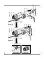
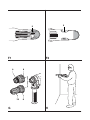
® D25112(K) D25113K D25114K D25213K 1 English 6 Ⱥড় 13 ०༹ዐ࿔ 20 ༹ݏዐ࿔ 27 34 Copyright DE WALT 2 3 9 7 4 5 4 5 3 1 2 1 6 11 10 D25213K 9 7 6 11 10 D25113K 8 4 D25112(K) D25114K A 3 4 5 6 B1 7 4 B2 12 5 C 10 9 D 4 E 11 3 3 F1 F2 8 6 13 G 8 H 5 ENGLISH HEAVY DUTY ROTARY HAMMER DEILL D25112(K)/D25113K/D25114K/D25213K Congratulations! You have chosen a DEWALT tool. Years of experience, thorough product development and innovation make DEWALT one of the most reliable partners for professional power tool users. Technical data Voltage Power input No-load speed Load speed Impact energy hammer drilling chiselling Maximum drilling range in steel/wood/concrete Chisel positions Core drilling capacity in soft brick Tool holder Collar diameter Weight V W min-1 min-1 D25112(K) 220 800 0 - 1,150 0 - 830 J 3.1 J mm 13/30/26 mm 68 SDS-plus® mm 54 kg 2.55 The following symbols are used throughout this manual: 6 D25113K 220 800 0 - 1,150 0 - 830 D25114K 220 800 0 - 1,150 0 - 830 D25213K 220 800 0 - 1,150 0 - 830 3.1 3.4 3.1 3.4 3.1 3.4 13/30/26 51 68 SDS-plus® 54 2.6 13/30/26 51 68 SDS-plus® 54 2.6 13/30/26 51 68 SDS-plus® 54 2.75 EC-Declaration of conformity Denotes risk of personal injury, loss of life or damage to the tool in case of nonobservance of the instructions in this manual. D25112(K)/D25113K/D25114K/D25213K DEWALT declares that these power tools have been designed in compliance with: 98/37/EEC, 89/336/EEC, 73/23/EEC, EN 50144, EN 55014-2, EN 55014-1, EN 61000-3-2 & EN 61000-3-3. Denotes risk of electric shock. For more information, please contact DEWALT at the address below, or refer to the back of the manual. Fire hazard. Level of sound pressure according to 86/188/EEC & 98/37/EEC, measured according to EN 50144: ENGLISH D25112(K ) D25113K LpA (sound pressure) dB(A)* 90.5 90.5 LWA (acoustic power) dB(A) 99 99 LpA (sound pressure) dB(A)* 90.5 LWA (acoustic power) dB(A) 99 D25114K * at the operator’s ear Take appropriate measures for the protection of hearing. Weighted root mean square acceleration value according to EN 50144: D25112(K ) D25113K D25114K D25213K 9.2 m/s2 9.2 m/s2 9.2 m/s2 9.2 m/s2 Director Engineering and Product Development Horst Großmann DEWALT, Richard-Klinger-Straße 11 D-65510, Idstein, Germany Safety instructions When us ing power tools , always obs erve the s afety regulations applic able in your c ountry to reduc e the ris k of fire, elec tric s hoc k and pers onal injury. R ead all of this manual c arefully before operating the tool. S ave this manual for future referenc e. General 1 K eep work area c lean Cluttered areas and benches can cause accidents. 2 C ons ider work area environment Do not expose the tool to rain. Do not use the tool in damp or wet conditions. Keep the work area well lit (250 - 300 Lux). Do not use the tool where there is a risk of causing fire or explosion, e.g. in the presence of flammable liquids and gases. 3 K eep c hildren away Do not allow children, visitors or animals to come near the work area or to touch the tool or the mains cable. 4 Dres s properly Do not wear loose clothing or jewellery, as these can be caught in moving parts. Wear protective hair covering to keep long hair out of the way. When working outdoors, preferably wear suitable gloves and non-slip footwear. 5 P ers onal protec tion Always use safety glasses. Use a face or dust mask whenever the operations may produce dust or flying particles. If these particles might be considerably hot, also wear a heat-resistant apron. Wear ear protection at all times. 6 G uard agains t elec tric s hoc k Prevent body contact with earthed surfaces (e.g. pipes, radiators, cookers and refrigerators). When using the tool under extreme conditions (e.g. high humidity, when metal swarf is being produced, etc.), electric safety can be improved by inserting an isolating transformer or a (FI) earth-leakage circuit-breaker. 7 Do not overreac h Keep proper footing and balance at all times. 8 S tay alert Watch what you are doing. Use common sense. Do not operate the tool when you are tired. 9 S ec ure workpiec e Use clamps or a vice to hold the workpiece. It is safer and it frees both hands to operate the tool. 10 C onnec t dus t extrac tion equipment If devices are provided for the connection of dust extraction and collection facilities, ensure that these are connected and properly used. 11 R emove adjus ting keys and wrenc hes Always check that adjusting keys and wrenches are removed from the tool before operating the tool. 12 E xtens ion c ables Before use, inspect the extension cable and replace if damaged. When using the tool outdoors, only use extension cables intended for outdoor use and marked accordingly. 13 Us e appropriate tool The intended use is described in this instruction manual. Do not force small tools or attachments to do the job of a heavy-duty tool. 7 ENGLISH 14 15 16 17 18 19 20 8 The tool will do the job better and safer at the rate for which it was intended. Do not force the tool. Warning! The use of any accessory or attachment or performance of any operation with this tool other than those recommended in this instruction manual may present a risk of personal injury. Check for damaged parts Before use, carefully check the tool and mains cable for damage. Check for misalignment and seizure of moving parts, breakage of parts, damage to guards and switches and any other conditions that may affect its operation. Ensure that the tool will operate properly and perform its intended function. Do not use the tool if any part is damaged or defective. Do not use the tool if the switch does not turn it on and off. Have any damaged or defective parts replaced by an authorised DEWALT repair agent. Never attempt any repairs yourself. Unplug tool Switch off and wait for the tool to come to a complete standstill before leaving it unattended. Unplug the tool when not in use, before changing any parts of the tools, accessories or attachments and before servicing. Avoid unintentional starting Do not carry the tool with a finger on the switch. Be sure that the tool is switched off before plugging in. Do not abuse cord Never carry the tool by its cord. Never pull the cord to disconnect from the socket. Keep the cord away from heat, oil and sharp edges. Store idle tools When not in use, tools must be stored in a dry place and locked up securely, out of reach of children. Maintain tools with care Keep the tools in good condition and clean for better and safer performance. Follow the instructions for maintenance and changing accessories. Keep all handles and switches dry, clean and free from oil and grease. Repairs This tool is in accordance with the relevant safety regulations. Have your tool repaired by an authorised DEWALT repair agent. Repairs should only be carried out by qualified persons using original spare parts; otherwise this may result in considerable danger to the user. Package contents The package contains: 1 Heavy duty rotary hammer drill 1 Side handle 1 Depth adjustment rod 1 Kitbox (K-models only) 1 Keyless chuck (D25114K) 1 Instruction manual 1 Exploded drawing • Check for damage to the tool, parts or accessories which may have occurred during transport. • Take the time to thoroughly read and understand this manual prior to operation. Your heavy duty rotary hammer drill D25112(K)/ D25113K/D25114K/D25213K has been designed for professional rotary and hammer drilling, screwdriving and light chipping, chiselling, demolition applications and for carbide tipped core drilling. 1 Variable speed switch 2 Lock-on button (D25112(K)/D25113K/D25114K) 3 Forward/reverse slider 4 Mode selector 5 Safety lock 6 Tool holder 7 Dust cover 8 Locking collar (D25114K) 9 Depth adjustment rod 10 Side handle 11 Depth stop clamp Torque limiting clutch All rotary hammer drills are equipped with a torque limiting clutch that reduces the maximum torque reaction transmitted to the operator in case of jamming of a drill bit. This feature also prevents the gearing and electric motor from stalling. The torque limiting clutch has been factory-set and cannot be adjusted. Electrical safety The electric motor has been designed for one voltage only. Always check that the power supply corresponds to the voltage on the rating plate. ENGLISH Your DEWALT tool is double insulated in accordance with EN 50144; therefore no earth wire is required. D25113K/D25114K/D25213K (fig. B2) The tool can be used in the following operating modes: Using an extension cable If an extension cable is required, use an approved extension cable suitable for the power input of this tool (see technical data). The minimum conductor size is 1.5 mm2. When using a cable reel, always unwind the cable completely. Also refer to the table below. Conductor size (mm 2 ) 0.75 1.00 1.50 2.50 4.00 230 Amperes - 0 2.0 2.1 - 3.4 3.5 - 5.0 5.1 - 7.0 7.1 - 12.0 12.1 - 20.0 0 - 2.0 2.1 - 3.4 3.5 - 5.0 5.1 - 7.0 7.1 - 12.0 12.1 - 20.0 15 Hammer drilling: for concrete and masonry drilling operations. In this mode the tool can also be used as a lever to free a jammed drill bit. 0 Cable length (m) 25 30 45 Cable rating (Amperes) 6 6 6 6 6 6 6 6 6 6 10 15 10 10 15 20 15 15 20 25 20 20 25 6 6 6 6 6 6 6 6 6 6 6 6 10 10 10 10 15 15 15 15 20 20 20 20 Rotary drilling: for screwdriving and for drilling into steel, wood and plastics Hammering only: for light chipping, chiselling and demolition applications. Cable rating (Amperes) 6 10 15 20 25 7.5 Voltage 115 Hammer drilling: for concrete and masonry drilling operations. 6 15 20 20 25 6 6 10 15 20 25 60 1 15 20 25 6 6 15 15 20 - Assembly and adjustment Prior to assembly and adjustment always unplug the tool. Bit rotation: non-working position used only to rotate a flat chisel into the desired position. • To select the operating mode, press the safety lock (5) and rotate the mode selector switch (4) until it points to the symbol of the required mode. • Release the safety lock and check that the mode selector switch is locked in place. Do not select the operating mode when the tool is running. Indexing the chisel position The chisel can be indexed and locked into 51 different positions. • Rotate the mode selector switch (4) until it points to the “bit rotation” position. • Rotate the chisel in the desired position. • Set the mode selector switch (4) to the “hammering only” position. • Twist the chisel until it locks in position. Selecting the operating mode (fig. B1 & B2) D25112(K) (fig. B1) The tool can be used in the following operating modes: Rotary drilling: for screwdriving and for drilling into steel, wood and plastics Inserting and removing SDS-plus® accessories (fig. C) This tool uses SDS-plus® accessories (refer to the inset in fig. B for a cross-section of an SDS-plus® bit shank). 9 ENGLISH We recommend to use professional accessories only. • Clean and grease the bit shank. • Insert the bit shank into the tool holder (6). • Push the bit down and turn it slightly until it fits into the slots. • Pull on the bit to check if it is properly locked. The hammering function requires the bit to be able to move axially several centimetres when locked in the tool holder. • To remove a bit pull back the tool holder locking sleeve (12) and pull out the bit. Fitting the side handle (fig. D) The side handle (10) can be fitted to suit both RH- and LH-users. Always use the tool with the side handle properly assembled. • Loosen the side handle. • For RH-users, slide the side handle clamp over the collar behind the tool holder, handle at the left. • For LH-users, slide the side handle clamp over the collar behind the tool holder, handle at the right. • Rotate the side handle to the desired position and tighten the handle. Setting the drilling depth (fig. E) • Insert the required drill bit as described above. • Press the depth stop clamp (11) and keep it depressed. • Fit the depth adjustment rod (9) through the hole in the depth stop clamp. • Adjust the drilling depth as shown. • Release the depth stop clamp. Forward/reverse slider (fig. F1 & F2) D25112(K)/D25113K/D25114K (fig. F1) • Push the forward/reverse slider (3) to the RH-side for forward (RH) rotation. See arrows on tool. • Push the forward/reverse slider (3) to the LH-side for reverse (LH) rotation. D25213K (fig. F2) • Push the forward/reverse slider (3) to the LH-side for forward (RH) rotation. See arrows on tool. 10 • Push the forward/reverse slider (3) to the RH-side for reverse (LH) rotation. Always wait until the motor has come to a complete standstill before changing the direction of rotation. D25112(K)/D25113K/D25213K Fitting the chuck adapter & chuck • Screw the chuck onto the threaded end of the chuck adapter. • Insert the connected chuck and adapter in the tool as though it were a standard SDS-plus® bit. • To remove the chuck, proceed as for removing a standard SDS-plus® bit. Never use standard chucks in the hammer drilling mode. D25114K - R eplac ing the tool holder with the c huc k (fig. G ) • Turn the locking collar (8) into the unlocking position and pull the tool holder (6) off. • Push the chuck (13) onto the spindle and turn the locking collar into the locking position. • To replace the chuck with the tool holder, first remove the chuck the same way as the tool holder was removed. Then place the tool holder the same way as the chuck was placed. Never use standard chucks in the hammer drilling mode. R eplac ing the dus t c over (fig. C ) The dust cover (7) prevents dust ingress into the mechanism. Replace a worn dust cover immediately. • Pull back the tool holder locking sleeve (12) and pull the dust cover (7) off. • Fit the new dust cover. • Release the tool holder locking sleeve. Instructions for use • Always observe the safety instructions and applicable regulations. ENGLISH Be aware of the location of pipework and wiring. Apply only a gentle pressure to the tool (approx. 5 kg). Excessive force does not speed up drilling but decreases tool performance and may shorten tool life. Do not drill or drive too deep to prevent damage to the dust cover. Always hold the tool firmly with both hands and ensure a secure stance (fig. H). Always operate the tool with the side handle properly mounted. Switching on and off (fig. A) D25112(K)/D25113K/D25114K • To run the tool, press the variable speed switch (1). The pressure exerted on the variable speed switch determines the tool speed. • For continuous operation, press and hold down the variable speed switch, press the lock-on button (2) and release the switch. • To stop the tool, release the switch. • To stop the tool in continuous operation, press the switch briefly and release it. Always switch off the tool when work is finished and before unplugging. D25213K • To run the tool, press the variable speed switch (1). The pressure exerted on the variable speed switch determines the tool speed. • To stop the tool, release the switch. • To lock the tool in off position, move the forward/ reverse slider (3) to the central position. Hammer drilling (fig. A) Drilling with a solid bit • Set the mode selector switch (4) to the “hammer drilling” position. • Insert the appropriate drill bit. For best results use high quality carbide-tipped bits. • Adjust the side handle (9) as required. • If necessary, set the drilling depth. • Mark the spot where the hole is to be drilled. • Place the drill bit on the spot and switch on the tool. • Always switch off the tool when work is finished and before unplugging. Drilling with a core bit • Set the mode selector (3) to the “hammer drilling” position. • Adjust the side handle (9) as required. • Insert the appropriate core bit. • Assemble the centerdrill into the core bit. • Place the centerdrill on the spot and press the variable speed switch (1). Drill until the core penetrates into the concrete approx. 1 cm. • Stop drilling and remove the centerdrill. Place the core bit back into the hole and continue drilling. • When drilling through a structure thicker than the depth of the core bit, break away the round cylinder of concrete or core inside the bit at regular intervals. To avoid unwanted breaking away of concrete around the hole, first drill a hole the diameter of the centerdrill completely through the structure. Then drill the cored hole halfway from each side. • Always switch off the tool when work is finished and before unplugging. Rotary drilling (fig. A) • Set the mode selector switch (4) to the “rotary drilling” position. • Depending on your tool, follow either of the following instructions: - Fit the chuck adapter/chuck assembly (D25112(K)/D25113K/D25213K). - Replace the tool holder with the chuck (D25114K). • Proceed as described for hammer drilling. Never use standard chucks in the hammer drilling mode. Screwdriving (fig. A) • Set the mode selector switch (4) to the “rotary drilling” position. • Select the direction of rotation. • Depending on your tool, follow either of the following instructions: - Insert the special SDS-plus® screwdriving adaptor for use with hexagonal screwdriver bits (D25112(K)/D25113K/D25213K). - Replace the tool holder with the chuck (D25114K). 11 ENGLISH • Insert the appropriate screwdriver bit. When driving slotted head screws always use bits with a finder sleeve. • Gently press the variable speed switch (1) to prevent damage to the screw head. In reverse (LH) rotation the tool speed is automatically reduced for easy screw removal. • When the screw is flush with the workpiece, release the variable speed switch to prevent the screw head from penetrating into the workpiece. D25113K/D25114K/D25213K - Chipping and chiselling (fig. A) • Set the mode selector switch (4) to the “hammering only” position. • Insert the appropriate chisel and rotate it by hand to lock it into one of 51 positions. • Adjust the side handle (9) as required. • Switch on the tool and start working. • Always switch off the tool when work is finished and before unplugging. • Do not use this tool to mix or pump easily combustible or explosive fluids (benzine, alcohol, etc.). • Do not mix or stir inflammable liquids labelled accordingly. Various types of SDS-plus® drill bits and chisels are available as an option. Consult your dealer for further information on the appropriate accessories. Maintenance Your DEWALT power tool has been designed to operate over a long period of time with a minimum of maintenance. Continuous satisfactory operation depends upon proper tool care and regular cleaning. • This machine is not user-serviceable. Take the tool to an authorised DEWALT repair agent after approximately 40 hours of use. If problems occur before this time contact an authorised DEWALT repair agent. • The tool will automatically switch off when the carbon brushes are worn. 12 Lubrication Your power tool requires no additional lubrication. Accessories and attachments used must be regularly lubricated around the SDS-plus® fitment. Cleaning Keep the ventilation slots clear and regularly clean the housing with a soft cloth. Unwanted tools and the environment Take your tool to an authorized DEWALT repair agent where it will be disposed of in an environmentally safe way.