1
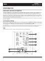
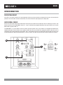
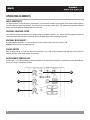
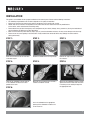
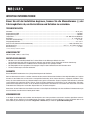
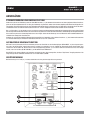
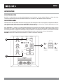
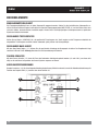
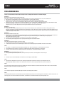
QB250 GOLF V
ENG
USER’S MANUAL................................2
DEU
BEDIENUNGSANLEITUNG .................9
QUARTBASS
ENG
2
QUARTBASS
ENG
IMPORTANT INFORMATIONS
Before you start with the installation, disconnect the ground connection from the
vehicle’s battery in order to prevent short circuits.
SPECIFICATIONS
Subwoofer...............................................................................................................................................................................25 cm (10“)
Output Power RMS.................................................................................................................................................................... 250 Watts
Output Power Max..................................................................................................................................................................... 500 Watts
Lowpassfilter.................................................................................................................................................50 - 200 Hz @ 12 dB/Octave
Bass Boost................................................................................................................................................................... 0 - 12 dB @ 45 Hz
Phase Shift..................................................................................................................................................................................0° / 180°
Input Sensitivity.........................................................................................................................................................................6 V - 0.2 V
Auto-Turn-On..........................................................................................................................................................Audio / DC-Offset / Off
Operating Voltage................................................................................................................................ +12 V (11 - 15 V), negative ground
Fuse rating................................................................................................................................................................................... 2 x 10 A
All Specifications are subject to change.
Compatibility
VW Golf V (2005 - 2008, 3- and 5-door)
Legal Note
•
•
•
• MB Quart or Audio Design GmbH is in no way affiliated with the Volkswagen AG or any of its subsidiaries
or affiliated companies connected to, or is acting on its behalf or with its authorization.
All registered product names, trade marks and brands are the property of their respective owners.
The compatibility with the specified types of vehicles reflects the information available on December 2012.
Technical changes and errors reserved.
WARRANTY
This MB Quart product has a 3-year warranty from date of purchase.
To maintain your warranty coverage upright, keep your original purchase receipt to prove the date of purchase. Any damage of the product,
based on incorrect or improper use, accident, incorrect and improper installation, modification of the barcode, natural disaster or any nonappropriate interventions, repairing or alteration outside our factory or authorized service centers, and caused by other acts, which are
unauthorized, because have been made in an incompetent manner, is excluded from the warranty. This warranty is limited only to defective
parts and especifically excludes all incidental or consequential damages and those who are associated with. Please return the defective product along with a copy of your purchase receipt and a detailed malfunction description to the dealer from whom you purchased the product.
CUSTOMer SerVICE
In general, the assembly and installation of the sound system should be made by a trained and technically skilled specialists. If you nonetheless choose the self-assembly and you have any problems, contact your specialist dealer or the Audio Design Service Department
under Tel. +49 (0) 7253 - 94 65 93 or by E-Mail to [email protected]
3
QUARTBASS
ENG
INTERCONNECTION
POWER SUPPLY AND TURN-ON-CONNECTION
First connect the GND terminal ( 2 ) of the power plug to an appropriate ground connection at the chassis. To ensure a good connection,
remove dirt and dust from the connection point. A loose connection may cause malfunctions or interferences noise and distortion.
Use at least a 10 mm2 cross-section for the power and ground connection cable. Suitable cable sets are available at the specialist shop.
Then connect the +12 V terminal ( 1 ) of the power plug with the battery by using an appropriate cable including an in-line fuse. This fuse
should be located very close to the battery; for safety reasons not more than 30 cm away. Only insert the fuse when the installation, including the connection of the loudspeakers, has been accomplished.
Then connect the remote turn-on-wire (Remote) from the headunit with the power plug‘s middle connector ( 3 ). A cable with a cross-section
of 0.5 mm2 is adequate.
AUTO TURN ON-FUNCTION
With this function the amplifier detects a voltage rise over the connected input signal on the AUDIO INPUT ( 4 ) when the headunit will be
switched on. Hence, the amplifier will also be turned on. As soon as the headunit will be turned off, the amplifier turns also automatically
off. In this case the turn-on connection ( 3 ) is not needed, if the switch ( 5 ) is in position DC OFFSET or AUDIO.
The DC OFFSET mode is the best choice for the Auto Turn On-function and usually works with 90% of all headunits, because they are
equipped with ”High Power”-outputs. Only with a few older and still existing headunits are working only with the AUDIO mode.
FUSE
Fuse with a rating of 2 x 10A ( 6 ). If the fuse is defective, please replace with an equivalent fuse.
GAIN
PHASE
INPUT
LEVEL
HIGH
AUTO
TURN ON
5
LOW
X-OVER
4
REMOTE
CONTROLLER AUDIO INPUT
BASS
BOOST
FUSE
6
FUSE
6
POWER
PROTECTION
3
1
2
–
4
+
ENG
INTERCONNECTION
PROTECTION CIRCUIT
If the LED ( 7 ) lits up blue, the device is in normal operation and lits up red, when the device is overheated. If this events, the internal built-in
protection circuit shuts down the device automatically. The device should work again properly after cooling down.
AUDIO SIGNAL CABLES
Connect the audio signal cables from the RCA outputs coming from the headunit with the RCA inputs of the included plug connector. Then
plug the connector into the AUDIO INPUT socket ( 4 ). If you use LOW level pre-amplifier RCA outputs from your headunit, set the switch
INPUT LEVEL on position LOW ( 8 ).
The AUDIO INPUT ( 4 ) is also suitable to connect the device input with speaker wires, if your headunit is not equipped with LOW level preamplifier RCA outputs. Extend therefor every regarding speaker cable from your headunit with appropriate speaker cables from your car
audio retailer to the mounting location of the amplifier. Then cut off the RCA jacks from the included cable connector plug and connect each
matching loudspeaker cable like described below ( 4 ). Ensure to detach the cable connector plug from the device before the cutting off.
GAIN
GAIN
PHASE
8
INPUT
LEVEL
HIGH
PHASE
AUTO
TURN ON
INPUT
LEVEL
HIGH
LOW
LOW
L+
X-OVER
X-OVER
4
REMOTE
CONTROLLER AUDIO INPUT
BASS
BOOST
BASS
BOOST
PROTECTION
FUSE
white
L–
REMOTE
white /
CONTROLLER
black AUDIO INPUT
FUSE
POWER
7
AUTO
TURN ON
R+
grey
R–
grey /
black
FUSE
POWER
PROTECTION
FUSE
5
QUARTBASS
ENG
OPERATING ELEMENTS
INPUT SENSITIVITY
The input sensitivity can be adjusted to any headunit. Turn the volume control of your headunit to the center medium position
and then adjust the input level controls ( 9 ) until you have an average medium level. This setting usually provides sufficient
power reserves at optimum weighted signal-to-noise ratio.
VARIABLE LOWPASS FILTER
Set the desired crossover frequency of the low pass filter by using the controller ( 10 ). Hence, only the frequencies below the
chosen crossover frequency will be amplified and the subwoofer plays more precised and efficient.
VARIABLE BASS BOOST
By using the boost controller ( 11 ) you are able to increase the bass boost level from 0 dB to 12 dB.
Caution: Please use the bass boost with care.
PHASE SWITCH
With the phase switch ( 12 ) you are able to turn the phase ( 0° or 180°) of the subwoofer audio signal to match it with the
satellite speakers of the sound systems if neccessary.
BASS REMOTE CONTROLLER
Remote jack ( 13 ) for the included bass remote controller. If the bass remote controller is connected it replaces the GAIN controller ( 9 ), which is then without function.
GAIN
PHASE
9
INPUT
LEVEL
HIGH
AUTO
TURN ON
LOW
12
X-OVER
13
10
REMOTE
CONTROLLER AUDIO INPUT
BASS
BOOST
11
FUSE
POWER
PROTECTION
FUSE
6
DEU
INSTALLATION
This guide is an installation aid for a proper installation of the sound system. Please read the following instructions:
• The reliability and performance of the device depends on the quality of installation.
• Please treat all parts of the sound system and the components of your vehicle with caution.
• Follow under all circumstance the regulations of the vehicle manufacturer and do not make any modifications
on the vehicle, which could interfere the driving safety.
• Please observe that you don’t damage any serial components of your vehicle (airbags, wires, gastank etc.) during the installation of your soundsystem by drilling or any other operations.
• Never screw or mount any other devices (amps, caps etc.) onto the subwoofer enclosure, this may cause damage to the electricity.
• Please ensure the correct polarity of all connections. Faulty installed and connected devices may damage the vehicle and the
device permanently.
STEP 1:
STEP 2:
STEP 3:
Clear the trunk area on the left and remove the floor carpet.
Remove the holder of the warning triangle.
Remove the eight screws on the subwoofer enclosure.
STEP 4:
STEP 5:
STEP 6:
Take out the subwoofer carefully and set
in the subwoofer enclosure to its final
position in the trunk.
Now take the included fixing screw and a
suitable screwdriver to hand.
Now press the subwoofer enclosure tightly
against the vehicle interior wall and screw
in the fixing screw carefully through the
the appropriate hole.
STEP 6:
Set in the subwoofer to the appropriate
opening of the subwoofer enclosure and
screw it back on.
7
ENG
QUARTBASS
TROUBLE SHOOTING
If you are having problems after installation follow the trouble shooting procedures below.
Procedure 1:
Check the device for proper connections.
Verify that the LED ( 7 ) lits up blue. If the LED lits up blue skip to Step 3, if not continue.
1. Check the fuses of the device or the external fuse on battery positive cable. Replace if necessary.
2. Verify that Ground connection is connected to clean metal on the vehicle’s chassis. Repair/replace if necessary.
Please ensure that you have reconnected the GND connection at the battery after the installation.
3. Verify that there are 11 to 15 Volts present at the positive battery and remote turn-on cable. Verify quality connections for both cables at device,
headunit and battery/fuseholder. Repair/replace if necessary. Check that the vehicle charging system is maintaining proper voltage.
Procedure 2:
The LED ( 7 ) lits up red.
1. If the LED lits up red, this is a sign of overheating and driving the device at very high power levels without adequate airflow around the device.
Shut off the system and allow device to cool down. If the previous items do not solve the problem, a fault may be in the device.
Check that the vehicle charging system is maintaining proper voltage.
Procedure 3:
Check the device for a proper audio signal.
1. Verify good RCA input connections at headunit and device. Check entire length of cables for kinks, splices, etc.
Test RCA inputs for AC volts with stereo on. Repair/replace if necessary.
2. Use another audio source for testing to provide an audio signal to the Line Input.
3. If you use high level speaker inputs, check the polarity.
Procedure 4:
Check the device for a popping noise while turning on.
1. Disconnect input signal to device and turn device on and off.
2. If the noise is eliminated, connect the REMOTE lead of device to source unit with a delay turn-on module.
OR
1. Use a different 12 Volt source for REMOTE lead of the device (e.g. battery direct just for testing).
2. If the noise is eliminated, use a relay to isolate the device from noisy turn-on output.
3. Don‘t connect REMOTE directly to the battery after testing to avoid a discharge of the battery.
Procedure 5:
Check the device if you experience excess Engine Noise.
1. Route all signal carrying wires (RCA, Speaker cables) away from power and ground wires.
OR
2. Bypass any and all electrical components between the headunit and the device. Connect the headunit
directly to input of the device. If noise goes away the unit being bypassed is the cause of the noise.
OR
3. Use another audio source for testing to provide an audio signal to the Line Input.
OR
4. Remove existing ground wires for all electrical components. Reground wires to different locations.
Verify that grounding location is clean, shiny metal free of paint, rust etc.
OR
5. Add secondary ground cable from negative battery terminal to the chassis metal or engine block of vehicle.
OR
6. Have alternator and battery load tested by your mechanic.Verify good working order of vehicle electrical system including distributor,
spark plugs, spark plug wires, voltage regulator etc.
8
DEU
WICHTIGE INFORMATIONEN
Bevor Sie mit der Installation beginnen, trennen Sie die Masseklemme (–) der
Fahrzeugbatterie ab, um Kurzschlüsse und Schäden zu vermeiden.
Technische Daten
Subwoofer...............................................................................................................................................................................25 cm (10“)
Ausgangsleistung RMS................................................................................................................................................................ 250 Watt
Ausgangsleistung Max . .............................................................................................................................................................. 500 Watt
Tiefpassfilter..................................................................................................................................................50 - 200 Hz @ 12 dB/Oktave
Bass Boost................................................................................................................................................................... 0 - 12 dB @ 45 Hz
Phase Shift (Phasendrehung).......................................................................................................................................................0° / 180°
Eingangsempfindlichkeit............................................................................................................................................................6 V - 0.2 V
Auto-Turn-On (Automatische Einschaltfunktion)..................................................................................................... Audio / DC-Offset / Aus
Betriebsspannung................................................................................................................................ +12 V (11 - 15 V), Minus an Masse
Gerätesicherung........................................................................................................................................................................... 2 x 10 A
Technische Änderungen und Irrtum vorbehalten.
Kompatibilität
VW Golf V (2005 - 2008, 3- und 5-Türer)
Rechtlicher Hinweis
•
•
•
• MB Quart bzw. die Audio Design GmbH sind in keiner Weise mit der Volkswagen AG oder einer ihrer Tochtergesellschaften oder Partner-Unternehmen verbunden, oder handeln in deren Auftrag oder mit deren Autorisierung.
Alle geschützten Produktnamen und Markennamen sind das Eigentum ihrer jeweiligen Inhaber.
Die Kompatibilität mit den angegebenen Fahrzeugtypen entspricht dem Informationsstand vom Dezember 2012.
Technische Änderungen und Irrtum vorbehalten.
Garantie
Dieses MB QUART Produkt besitzt eine 3-jährige Herstellergarantie ab Kaufdatum.
Um Ihren Garantieschutz aufrecht zu erhalten, bewahren Sie bitte zwecks Nachweis des Kaufdatums Ihren Originalkaufbeleg auf. Jeglicher
Schaden an dem Produkt, der auf falsche bzw. unsachgemäße Verwendung, Unfall, falschen Anschluss, ungeeignete Installation, Veränderung der Strichcodekennzeichnung, Naturkatastrophen oder jegliche zweckfremden Eingriffe, Reparatur oder Abänderung außerhalb
unseres Werkes oder autorisierter Service-Zentren, sowie alle anderen Handlungen zurückzuführen ist, die unberechtigter, weil inkompetenter Weise vorgenommen wurden, ist von der Garantie ausgeschlossen. Diese Garantie ist auf defekte Teile beschränkt und schließt
insbesondere alle zufälligen bzw. eventuellen Folgeschäden aus, die damit einhergehen.
.
Retournieren Sie das Produkt bei einem Defekt zusammen mit einer Kopie des Kaufbelegs und einer detaillierten Fehlerbeschreibung an
Ihren Fachhändler, von dem Sie das Produkt gekauft haben.
Kundenservice
In der Regel ist die Montage und Installation des Soundsystems von einem geschultem und technisch versierten Spezialisten vorzunehmen. Sollten Sie sich dennoch für eine Selbstmontage entscheiden, wenden Sie sich bei Problemen an Ihren Fachhändler oder an die
Serviceabteilung von Audio Design unter Tel. +49 (0) 7253 - 94 65 93 oder per E-Mail an [email protected]
9
QUARTBASS
DEU
ANSCHLÜSSE
STROMVERSORGUNG UND EINSCHALTLEITUNG
Stellen Sie zunächst eine Verbindung zwischen dem GND-Anschluss ( 2 ) des Stromanschlusssteckers und einem geeigneten Masse-Anschlusspunkt an der Fahrzeugkarosserie her. Um eine gute Verbindung zu garantieren, sollten Schmutzreste sorgfältig vom Masse-Anschlusspunkt entfernt werden. Ein lockerer Anschluss kann eine Fehlfunktion oder Störgeräusche und Verzerrungen zur Folge haben. Verwenden Sie für den Stromund Masseanschluss ein Kabel mit einem Querschnitt von min. 10 mm2. Geeignete Anschluss-Sets erhalten Sie im Fachhandel.
Der +12 V-Anschluss ( 2 ) des Steckers muss nun mit einem ausreichend dimensionierten Stromkabel mit integrierter Sicherung mit dem Pluspol
der Fahrzeug-Batterie verbunden werden. Die externe Sicherung sollte sich in Nähe der Batterie befinden, die Kabellänge vom Pluspol der Batterie
bis zur Sicherung muss aus Sicherheitsgründen unter 30 cm liegen. Setzen Sie die Sicherung erst nach Abschluss aller Installationsarbeiten einschließlich der Lautsprecher-Anschlüsse ein. Schließen Sie nun die Einschaltleitung (Remote) des Steuergeräts bzw. Autoradios an den mittleren Anschluss ( 3 ) des Stromanschlusssteckers
an. Für diese Verbindung ist ein Kabel mit einem Querschnitt von ca. 0,5 mm2 ausreichend.
AUTOMATISCHE EINSCHALTFUNKTION
Mit Auto-Turn-On (Automatische Einschaltfunktion) erkennt der Verstärker an den Audioeingängen (AUDIO INPUT, 4 ) einen Spannungsantieg, wenn das Steuergeräte angeschaltet wird und schaltet sich automatisch mit ein. Sobald das Steuergerät wieder abgeschaltet wird,
schaltet sich der Verstärker ab. Der Anschluss für die Einschaltleitung (Remote, 3 ) ist in diesem Falle ohne Funktion und muss nicht belegt
werden, wenn der Schalter (AUTO TURN ON, 5) auf DC-OFFSET oder AUDIO steht.
DC-OFFSET ist der bessere Modus und funktioniert prinzipiell mit 90% aller Steuergeräten, da diese ”High Power”-Ausgänge besitzen. Nur
einige wenige älteren Autoradios funktionieren nur mit dem Modus „AUDIO“.
GERÄTESICHERUNG
Gerätesicherung mit 2 x 10A ( 6 ). Ist diese defekt bitte mit einer gleichwertigen Sicherung ersetzen.
GAIN
PHASE
INPUT
LEVEL
HIGH
AUTO
TURN ON
5
LOW
X-OVER
4
REMOTE
CONTROLLER AUDIO INPUT
BASS
BOOST
FUSE
6
FUSE
6
POWER
PROTECTION
3
1
2
–
10
+
DEU
ANSCHLÜSSE
SCHUTZSCHALTUNG
Die LED ( 7 ) leuchtet blau auf, wenn das Gerät betriebsbereit ist und leuchtet rot auf, wenn das Gerät überhitzt ist. Wenn dies eintritt,
schaltet die integrierte Schutzschaltung das Gerät automatisch aus und sollte nach dem Abkühlen wieder funktionieren.
AUDIOSIGNALKABEL
Verbinden Sie die Audio-Signalkabel von den Cinch-Ausgänge aus dem Steuergerät mit den Cinch-Eingängen des mitgelieferten Kabelsteckers. Stecken Sie dann den Stecker in die Buchse AUDIO INPUT (4). Wenn Sie die Cinch-Vorverstärker-Ausgänge (Niedrigpegel) von Ihrem
Steuergerät verwenden, stellen Sie den Schalter INPUT LEVEL auf Position LOW ( 8 ).
Unter AUDIO INPUT ( 4 ) können auch Lautsprecherkabel (Hochpegel) zur Ansteuerung des Verstärkers angeschlossen werden, wenn Ihr
Steuergerät nicht mit Cinch-Vorverstärker-Ausgängen ausgestattet. Verlängern Sie dazu die entsprechenden Lautsprecherkabel, die aus
Ihrem Steuergerät führen mit geeigneten hochwertigen Lautsprecherkabel bis zum Einbauort des Verstärkers. Trennen Sie dafür die beiden
Cinchstecker ab und verbinden Sie das passende Lautsprecherkabel direkt mit den Anschlüssen wie unter ( 4 ) beschrieben. ACHTUNG: Entfernen Sie den Anschlussstecker am Gerät ( 4 ) bevor Sie die Stecker abschneiden.
INPUT
AUTO
GAIN
GAIN
PHASE
8
INPUT
LEVEL
HIGH
PHASE
AUTO
TURN ON
LEVEL
HIGH
LOW
LOW
X-OVER
X-OVER
4
REMOTE
CONTROLLER AUDIO INPUT
BASS
BOOST
FUSE
weiß
L–
schwarz
BASS
BOOST
PROTECTION
L+
REMOTE
weiß / AUDIO INPUT
CONTROLLER
FUSE
POWER
7
TURN ON
R+
grau
R–
grau /
schwarz
FUSE
POWER
PROTECTION
FUSE
11
QUARTBASS
DEU
BEDIENELEMENTE
EINGANGSEMPFINDLICHKEIT
Die Eingangsempfindlichkeit kann an jedes Steuergerät angepasst werden. Stellen Sie die Lautstärke des Steuergeräts zunächst auf einen mittleren Pegel ein und stellen Sie dann die Eingangspegelregler (INPUT LEVEL, 9 ) am Verstärker so ein, dass
sich eine mittlere, durchschnittliche Lautstärke ergibt. Hierbei sind in der Regel genügend Leistungsreserven bei optimalem
Signalrauschabstand vorhanden.
REGELBARER TIEFPASSFILTER
Stellen Sie am Regler ( LOW PASS, 10 ) die gewünschte Trennfrequenz ein. Somit werden nur die Frequenzen unterhalb der
eingestellten Trennfrequenz verstärkt und der Subwoofer spielt präziser und leistungsfähiger.
REGELBARER BASS-BOOST
Mit dem Bass Boost Regler ( 11 ) können Sie die gewünschte Anhebung des Basspegels einstellen. Der Regelbereich liegt
zwischen 0 dB und 12 dB. Achtung: Benutzen Sie die Bassanhebung mit Bedacht.
PHASEN-SCHALTER
Mit dem Phasen-Schalter ( 12 ) kann die Phase des Subwoofer-Audiosignals gedreht werden ( 0° oder 180°), um dieses falls
nötig an die restlichen Lautsprecher des Sound-Systems anpassen zu können.
KABELBASSFERNBEDIENUNG
Remote-Anschluss ( 13 ) für die beiliegende Kabelbassferbedienung. Wird diese benutzt, ersetzt die Kabelbassferbedienung die
Funktion des Reglers GAIN ( 9 ), welcher dann ohne Funktion ist.
GAIN
PHASE
9
INPUT
LEVEL
HIGH
AUTO
TURN ON
LOW
12
X-OVER
13
10
REMOTE
CONTROLLER AUDIO INPUT
BASS
BOOST
11
FUSE
POWER
PROTECTION
FUSE
12
DEU
INSTALLATION
Die vorliegende Anleitung ist eine Einbauhilfe zur fachgerechten Montage des Soundsystems. Beachten Sie dazu die folgenden Hinweise:
• Die Leistung und Zuverlässigkeit des Soundsystems ist von der Qualität des Einbaus abhängig.
• Behandeln Sie bitte alle Teile des Soundsystems und die Komponenten Ihres Fahrzeugs grundsätzlich mit Vorsicht.
• Beachten Sie unter allen Umständen die Vorschriften des Fahrzeugherstellers und nehmen Sie keine Veränderungen
am Fahrzeug vor, welche die Fahrsicherheit beeinträchtigen könnten.
• Achten Sie bei der Installation und der Befestigung des Geräts unbedingt darauf, dass keine serienmäßige Komponenten des
Fahrzeugs (Airbags, Sicherheitsgurte, Kabelstränge, Benzintank etc.) durch Bohrlöcher oder ähnliches beschädigt werden.
• Schrauben Sie bitte keine anderen Geräte wie z.B. Verstärker auf das Gehäuse. Dadurch könnte die Elektronik beschädigt werden.
• Bitte beachten Sie unbedingt die korrekte Polung der Anschlüsse. Falsch installierte oder angeschlossene Geräte können Ihr
Fahrzeug und das Gerät selbst dauerhaft beschädigen.
SCHRITT 1:
SCHRITT 2:
SCHRITT 3:
Räumen Sie den linken Stauraum frei und
entfernen den Teppich am Kofferraumboden.
Entfernen Sie den Halter des Warndreiecks.
Entfernen Sie die acht Schrauben am
Subwoofer-Gehäuse.
SCHRITT 4:
SCHRITT 5:
SCHRITT 6:
Entnehmen Sie den Subwoofer sorgfältig
und setzen das Subwoofer-Gehäuse an seine endgültige Position im linken Stauraum.
Nehmen Sie jetzt die beiliegende Befestigungsschraube und einen geeigneten
Schraubendreher zur Hand.
Drücken Sie jetzt das Subwoofer-Gehäuse
fest gegen die Fahrzeuginnenwand und
schrauben die Befestigungsschraube
durch das dafür vorgesehene Loch.
SCHRITT 6:
Setzen Sie den Subwoofer wieder in die
Öffnung des Subwoofer-Gehäuses ein und
schrauben ihn wieder fest.
13
DEU
QUARTBASS
FEHLERBEHEBUNG
Falls Sie nach dem Einbau Probleme haben, befolgen Sie die nachfolgenden Verfahren zur Fehlerbeseitigung:
Verfahren 1:
Das Gerät auf ordnungsgemäße Anschlüsse überprüfen.
Prüfen Sie, ob die LED ( 7 ) blau aufleuchtet. Leuchtet die LED blau auf, bei Schritt 3 weitermachen, falls nicht, hier weitermachen.
1. Die Sicherungen am Gerät oder die externe Sicherung überprüfen und nach Bedarf ersetzen.
2. Überprüfen Sie, ob der Masseanschluss korrekt angeschlossen ist. Nach Bedarf reparieren oder ersetzen.
Stellen Sie sicher, dass Sie nach der Installation den Masseanschluss wieder an die Batterie angeschlossen haben.
3. Überprüfen Sie, ob am +12V Anschluss und der Einschaltleitung 11 bis 15 Volt anliegen. Die Qualität der Anschlüsse für beide Kabel am Gerät,
Steuergerät (Autoradio) und Batterie- bzw. Sicherungshalter überprüfen. Nach Bedarf reparieren oder ersetzen.
Überprüfen Sie auch, ob das Ladesystem des Fahrzeugs die erforderliche Spannung aufrechterhält.
Verfahren 2:
Die LED ( 7 ) leuchtet rot auf.
1. Leuchtet die LED rot aufgrund Überhitzung auf, kann dies ein Zeichen dafür sein, dass das Gerät auf sehr hoher Leistung gefahren wird, .
ohne dass ein adäquater Luftstrom um das Gerät herum vorhanden ist. Dann sollten Sie das System ausschalten und das Gerät abkühlen lassen. Überprüfen Sie auch, ob das Ladesystem des Fahrzeugs die erforderliche Spannung aufrechterhält. Sollte keiner dieser Schritte Abhilfe schaffen, .
ist das Gerät möglicherweise defekt.
Verfahren 3:
Das Gerät auf Audioleistung überprüfen.
1. Gewährleisten Sie, dass gute RCA/Cinch-Eingangsanschlüsse am Steuergerät (Autoradio) und Gerät anliegen. Die gesamte Länge der Kabel auf Knicke, Spleiße usw. überprüfen. Die RCA/Cinch-Eingänge bei eingeschaltetem Stereosystem auf Wechselspannung überprüfen. .
Nach Bedarf reparieren bzw. ersetzen.
2. Schließen Sie eine andere Audioquelle für Testzwecke an die Eingänge von LINE INPUT.
3. Bei Verwendung von Hochpegelanschlüssen (Lautsprecherkabel), prüfen Sie bitte die Polarität.
Verfahren 4:
Prüfen ob beim Anstellen des Geräts ein Knacken auftritt.
1. Das Eingangssignal zum Gerät entfernen und das Gerät ein- und ausschalten.
2. Ist das Geräusch eliminiert, die Einschaltleitung des Geräts mit einem Verzögerungseinschaltmodul am Steuererät anschließen.
ODER
1. Eine andere +12 V Quelle für die Einschaltleitung des Geräts (z.B. direkt an der Batterie, nur für Testzwecke) verwenden.
2. Falls das Geräusch dann elimiert ist, ein Relais zur Isolierung des Geräts von Anschaltgeräuschen verwenden.
3. Schließen Sie keinesfalls die Einschaltleitung dauerhaft an der Batterie an, dies könnte die Batterie entladen.
Verfahren 5:
Das Gerät auf übermäßige Motorengeräusche prüfen.
1. Alle signalübertragenden Kabel (RCA/Cinch-, Lautsprecherkabel) von Strom- und Erdungskabeln entfernt verlegen.
ODER
2. Schließen Sie eine andere Audioquelle für Testzwecke an die Eingänge von LINE INPUT.
ODER
3. Alle elektrischen Komponenten zwischen dem Steuergerät (Autoradio) und dem Gerät umgehen. Das Steuergerät direkt am
Signaleingang des Geräts anschließen. Falls das Geräusch eliminiert ist, ist das umgangene Gerät die Ursache des Geräuschs.
ODER
4. Die vorhandenen Massekabel aller elektrischen Komponenten entfernen. Die Kabel an anderen Stellen wieder erden. Prüfen, ob der verwendete Massepunkt sauber, blank und frei von Farbe, Rost usw. ist.
ODER
5. Ein zweites Erdungskabel vom Minus/Massepol der Batterie zum Massepunkt installieren.
ODER
6. Die Drehstromlichtmaschine und Batterieladung von der Autowerkstatt prüfen lassen. Die ordnungsgemäße Funktion des elektrischen Systems am Fahrzeug prüfen, und zwar einschließlich des Verteilers, der Zündkerzen, der Zündkerzenkabel, des Spannungsreglers usw.
14
DEU
15
Audio Design GmbH
Am Breilingsweg 3 · D-76709 Kronau/Germany
Tel. +49(0)7253 - 9465-0 · Fax +49(0)7253 - 946510
www.audiodesign.de
©2012 Audio Design GmbH, All Rights Reserved
DESIGN