1
Model PM-15S2 User Guide
Integrated Amplifier
CAUTION
RISK OF ELECTRIC SHOCK DO NOT OPEN
CAUTION: TO REDUCE THE RISK OF ELECTRIC SHOCK,
DO NOT REMOVE COVER (OR BACK) NO USER-SERVICEABLE PARTS
INSIDE REFER SERVICING TO QUALIFIED SERVICE PERSONNEL
The lightning flash with arrowhead symbol within an equilateral triangle is intended to alert the user to the presence
of uninsulated “dangerous voltage” within the product’s enclosure that may be of sufficient magnitude to constitute a
risk of electric shock to persons.
The exclamation point within an equilateral triangle is intended to alert the user to the presence of important
operating and maintenance (servicing) instructions in the literature accompanying the product.
WARNING
TO REDUCE THE RISK OF FIRE OR ELECTRIC SHOCK, DO NOT EXPOSE THIS APPLIANCE TO
RAIN OR MOISTURE.
CAUTION:
TO PREVENT ELECTRIC SHOCK, MATCH WIDE BLADE OF PLUG TO WIDE SLOT, FULLY
INSERT.
ATTENTION: POUR EVITER LES CHOCS ELECTRIQUES, INTRODUIRE LA LAME LA PLUS LARGE DE LA
FICHE DANS LA BORNE CORRESPONDANTE DE LA PRISE ET POUSSER JUSQU’AU FOND.
NOTE:
This equipment has been tested and found to comply with
the limits for a Class B digital device, pursuant to Part 15
of the FCC Rules. These limits are designed to provide
reasonable protection against harmful interference in a
residential installation. This equipment generates, uses and
can radiate radio frequency energy and, if not installed and
used in accordance with the instructions, may cause harmful
interference to radio communications. However, there is
no guarantee that interference will not occur in a particular
installation. If this equipment does cause harmful interference
to radio or television reception, which can be determined by
turning the equipment off and on, the user is encouraged to
try to correct the interference by one or more of the following
measures:
- Increase the separation between the equipment and
receiver.
- Connect the equipment into an outlet on a circuit different
from that to which the receiver is connected.
- Consult the dealer or an experienced radio/TV technician
for help.
NOTE:
Changes or modifications may cause this unit to fail to
comply with Part 15 of the FCC Rules and may void the
user's authority to operate the equipment.
- Reorient or relocate the receiving antenna.
This Class B digital apparatus complies with Canadian
ICES-003.
Cet appareil numerique de la Classe B est conforme a la
norme NMB-003 du Canada.
IMPORTANT SAFETY INSTRUCTIONS
READ BEFORE OPERATING EQUIPMENT
This product was designed and manufactured to meet strict quality and safety standards.
There are, however, some installation and operation precautions which you should be particularly aware of.
1. Read these instructions.
2. Keep these instructions.
3. Heed all warnings.
4. Follow all instructions.
5. Do not use this apparatus near water.
6. Clean only with dry cloth.
7. Do not block any ventilation openings. Install in accordance with the manufacture's instructions.
8. Do not install near any heat sources such as radiators, heat registers, stoves, or other apparatus (including amplifiers) that
produce heat.
9. Do not defeat the safety purpose of the polarized or grounding-type plug. A polarized plug has two blades with one wider
than the other. A grounding type plug has two blades and a third grounding prong. The wide blade or the third prong are
provided for your safety. If the provided plug does not fit into your outlet, consult an electrician for replacement of the
obsolete outlet.
10. Protect the power cord from being walked on or pinched particularly at plugs, convenience receptacles, and the point where
they exit from the apparatus.
11. Only use attachments/accessories specified by the manufacturer.
12. Use only with the cart, stand, tripod, bracket, or table specified by the manufacturer, or sold with the apparatus. When a cart
is used, use caution when moving the cart/apparatus combination to avoid injury from tip-over.
13. Unplug this apparatus during lightning storms or when unused for long periods of time.
14. Refer all servicing to qualified service personnel. Servicing is required when the apparatus has been damaged in any
way, such as power-supply cord or plug is damaged, liquid has been spilled or objects have fallen into the apparatus, the
apparatus has been exposed to rain or moisture, does not operate normally, or has been dropped.
Additional Safety Information!
• This product should not be placed in a built-in installation such as a bookcase or rack unless proper ventilation is provided or
the manufacturer’s instructions have been adhered to.
• Apparatus shall not be exposed to dripping or splashing and that no objects filled with liquids, such as vases, shall be placed
on the apparatus.
• When the switch is in the OFF position, the apparatus isn’t completely switched-off from the MAINS.
• The equipment shall be installed near the power supply so that the power supply is easily accessible.
• Do not expose the unit to excessive heat such as direct sunlight, fire or the like.
AMPRC_090130U2
ENGLISH
WARRANTY
For warranty information, contact your local Marantz distributor.
RETAIN YOUR PURCHASE RECEIPT
Your purchase receipt is your permanent record of a valuable purchase.
It should be kept in a safe place to be referred to as necessary for
insurance purposes or when corresponding with Marantz.
IMPORTANT
When seeking warranty service, it is the responsibility of the consumer to
establish proof and date of purchase. Your purchase receipt or invoice is
adequate for such proof.
FOR U.K. ONLY
This undertaking is in addition to a consumer's statutory rights and
does not affect those rights in any way.
NEDERLANDS
GARANTIE
Voor inlichtingen omtrent garantie dient u zich tot uw plaatselijke
Marantz.
UW KWITANTIE, KASSABON E.D. BEWAREN
Uw kwitantie, kassabon e.d. vormen uw bewijs van aankoop van
een waardevol artikel en dienen op een veilige plaats bewaard te
worden voor evt, verwijzing bijv, in verbend met verzekering of bij
correspondentie met Marantz.
BELANGRIJK
Bij een evt, beroep op de garantie is het de verantwoordelijkheid van de
consument een gedateerd bewijs van aankoop te tonen. Uw kassabon
of factuurzijn voldoende bewijs.
ITALIANO
FRANÇAIS
GARANTIE
Pour des informations sur la garantie, contacter le distributeur local
Marantz.
CONSERVER L'ATTESTATION D'ACHAT
L'attestation d'achat est la preuve permanente d'un achat de valeur.
La conserver en lieu sur pour s'y reporter aux fins d'obtention d'une
couverture d'assurance ou dans le cadre de correspondances avec
Marantz.
IMPORTANT
Pour l'obtention d'un service couvert par la garantie, il incombe au
client d'établir la preuve de l'achat et d'en corroborer la date. Le reçu
ou la facture constituent des preuves suffisantes.
DEUTSCH
GARANTIE
Bei Garantiefragen wenden Sie sich bitte an Ihren Marantz-Händler.
HEBEN SIE IHRE QUITTING GUT AUF
Die Quittung dient Ihnen als bleibende Unterlage für Ihren wertvollen
Einkauf Das Aufbewahren der Quittung ist wichtig, da die darin
enthaltenen Angaben für Versicherungswecke oder bei Korrespondenz
mit Marantz angeführt werden müssen.
WICHTIG!
Bei Garantiefragen muß der Kunde eine Kaufunterlage mit
Kaufdatum vorlegen. Ihren Quittung oder Rechnung ist als Unterlage
ausreichend.
GARANZIA
L’apparecchio è coperto da una garanzia di buon funzionamento della
durata di un anno, o del periodo previsto dalla legge, a partire dalla
data di acquisto comprovata da un documento attestante il nominativo
del Rivenditore e la data di vendita. La garanzia sarà prestata con la
sostituzione o la riparazione gratuita delle parti difettose.
Non sono coperti da garanzia difetti derivanti da uso improprio, errata
installazione, manutenzione effettuata da personale non autorizzato
o, comunque, da circostanze che non possano riferirsi a difetti di
funzionamento dell’apparecchio. Sono inoltre esclusi dalla garanzia
gli interventi inerenti l’installazione e l’allacciamento agli impianti di
alimentazione.
Gli apparecchi verranno riparati presso i nostri Centri di Assistenza
Autorizzati. Le spese ed i rischi di trasporto sono a carico del cliente.
La casa costruttrice declina ogni responsabilità per danni diretti o indiretti
provocati dalla inosservanza delle prescrizioni di installazione, uso e
manutenzione dettagliate nel presente manuale o per guasti dovuti ad uso
continuato a fini professionali.
CE MARKING
English
The PM-15S2 is in conformity with the EMC directive and
low-voltage directive.
Français
Le PM-15S2 est conforme à la directive EMC et à la directive
sur les basses tensions.
Deutsch
Das Modell PM-15S2 entspricht den EMC-Richtlinien und
den Richtlinien für Niederspannungsgeräte.
Nederlands
De PM-15S2 voldoet aan de EMC eisen en de vereisten
voor laag-voltage.
Italiano
Il PM-15S2 è conforme alle direttive CEE ed a quelle per i
bassi voltaggi.
English
-
WARNINGS
Do not expose the equipment to rain, moisture, dripping or
splashing.
Do not remove the cover from the equipment.
Do not insert anything into the equipment through the ventilation
holes.
Do not handle the mains cord with wet hands.
Do not cover the ventilation with any items such as tablecloths,
newspapers, curtains, etc.
No naked flame sources, such as lighted candles, should be placed
on the equipment.
No objects filled with liquids, such as vases, shall be placed on the
equipment.
When the switch is in the OFF position, the equipment is not
completely switched off from MAINS.
The equipment shall be installed near the power supply so that the
power supply is easily accessible.
Do not expose the unit to excessive heat such as direct sunlight, fire
or the like.
Deutsch
WARNHINWEISE
- Das Gerät nicht Regen, Feuchtigkeit, Tropf- oder Spritzwasser
aussetzen.
- Die Abdeckung nicht vom Gerät abnehmen.
- Keine Gegenstände durch die Belüftungsschlitze stecken.
- Das Netzkabel nicht mit feuchten oder nassen Händen anfassen.
- Decken Sie die Lüftungsöffnungen nicht mit einem Tischtuch, einer
Zeitung, einem Vorhang usw. ab.
- Es dürfen keine Gegenstände mit offener Flamme, wie etwa
brennende Kerzen, auf dem Gerät aufgestellt werden.
- Auf das Gerät dürfen keine mit Flüssigkeiten gefüllte Behälter, wie
etwa eine Vase, gestellt werden.
- Wenn der Schalter ausgeschaltet ist (OFF-Position), ist das Gerät
nicht vollständig vom Stromnetz (MAINS) abgetrennt.
- Das Gerät sollte in der Nähe einer Netzsteckdose aufgestellt
werden, damit es leicht an das Stromnetz angeschlossen werden
kann.
- Setzen Sie das Gerät keiner übermäßigen Wärme aus, z.B. durch
Aufstellung in direkter Sonneneinstrahlung, in der Nähe eines
offenen Feuers usw.
Nederlands
-
WAARSCHUWINGEN
Stel het apparaat niet bloot aan regen, vocht, druppels of spetters.
Verwijder de afdekplaat van het apparaat niet.
Duw niets door de ventilatieopeningen in het apparaat.
Raak het netsnoer niet met natte handen aan.
Bedek de ventilatieopeningen niet met enige voorwerpen, zoals
tafelkleden, kranten, gordijnen, enz.
Plaats geen brandende voorwerpen, zoals kaarsen, op het
apparaat.
Plaats geen voorwerpen met een vloeistof erin, zoals een
bloemenvaas, op het apparaat.
Als de schakelaar op OFF staat, is het apparaat niet volledig
losgekoppeld van de netspanning (MAINS).
De apparatuur wordt in de buurt van het stopcontact geïnstalleerd,
zodat dit altijd gemakkelijk toegankelijk is.
Stel het apparaat niet bloot aan grote warmte, zoals direct zonlicht,
vuur en dergelijke.
Italiano
Français
AVERTISSEMENTS
- Ne pas exposer l’appareil à la pluie, à l’humidité, à l’égouttement ou
aux éclaboussures.
- Ne pas essayer de retirer le boîtier de l’appareil.
- Ne rien insérer dans l’appareil par les orifices de ventilation.
- Ne pas manipuler le cordon d’alimentation avec les mains
mouillées.
- Ne pas recouvrir les ouïes de ventilation avec un objet quelconque
comme une nappe, un journal, un rideau, etc.
- Ne placer aucune source de flamme nue, comme une bougie
allumée, sur l'appareil.
- Aucun objet rempli de liquide, un vase par exemple, ne doit être placé
sur l'appareil.
- Lorsque l'interrupteur est sur la position OFF, l'appareil n'est pas
complètement déconnecté du SECTEUR (MAINS).
- L'appareil sera installé près de la source d'alimentation, de sorte que
cette dernière soit facilement accessible.
- Ne pas exposer l’appareil à une chaleur excessive, comme celle des
rayons directs du soleil, d’un feu, etc.
AVVERTENZE
- Non esporre l’apparecchio alla pioggia, all’umidità, al gocciolamento
o agli spruzzi.
- Non rimuovere il coperchio dell’apparecchio.
- Non introdurre oggetti all’interno dell’apparecchio attraverso i fori di
ventilazione.
- Non toccare il cavo di alimentazione con le mani bagnate.
- Non coprire le fessure di ventilazione con tovaglie, giornali, tende od
oggetti analoghi.
- Non posare sull'apparecchio sorgenti di fiamme scoperte quali
candele accese.
- Non mettere sull'apparecchiatura alcun contenitore di liquido, come
ad esempio dei vasi.
- Quando l'interruttore è nella posizione OFF, l'apparecchiatura non è
completamente scollegata da MAINS.
- L’apparecchio va installato in prossimità della fonte di alimentazione,
in modo che quest’ultima sia facilmente accessibile.
- Non esporre l’unità ad eccessivo calore come la luce diretta del sole,
il fuoco o simili.
AMPRC_090130N1
ENGLISH
FRANÇAIS
DEUTSCH
NEDERLANDS
ITALIANO
ENGLISH
NOTA SUL RICICLAGGIO
I materiali di imballaggio di questo prodotto sono riciclabili e possono essere riutilizzati. Questo prodotto e gli accessori in dotazione con esso, eccettuate
le batterie, rappresentano il prodotto applicabile per la direttiva RAEE (rifiuti di apparecchiature elettriche ed elettroniche).
Smaltirli seguendo le proprie normative locali sul riciclaggio.
Quando si desidera eliminare l’apparecchio, attenersi alle indicazioni e alle normative locali.
Non gettare via le batterie e non bruciarle, ma smaltirle in conformità alle normative locali relative ai rifiuti chimici.
INFORMATION FOR USERS ON COLLECTION AND DISPOSAL OF OLD EQUIPMENT AND
USED BATTERIES
FRANÇAIS
RECYCLING VAN APPARATUUR EN VERPAKKINGSMATERIAAL
De verpakking van dit product is geschikt voor recycling. Dit product en de accessoires, als geheel verpakt, zijn het relevante product volgens de WEEErichtlijn, behalve de batterijen.
Gooi materialen bij het afval volgens de gemeentelijke voorschriften voor recycling.
Gooi dit apparaat bij het afval volgens de gemeentelijke wetten of voorschriften.
Batterijen mogen nooit bij het normale afval en mogen nooit worden verbrand, maar moeten worden weggegooid volgens de gemeentelijke voorschriften
voor chemisch afval.
INFORMATION CONCERNANT LA COLLECTE ET LE TRAITEMENT DES PILES USAGÉES ET DES
DÉCHETS D’ÉQUIPEMENTS ÉLECTRIQUES ET ÉLECTRONIQUES
DEUTSCH
RECYCLING-HINWEIS
Das Verpackungsmaterial dieses Produkts ist für Recycling geeignet und kann wiederverwendet werden. Dieses Produkt und das in seinem
Verpackungskarton enthaltene Zubehör mit Ausnahme der Batterien entsprechen der WEEE-Direktive.
Bitte beachten Sie bei der Entsorgung irgendwelcher Materialien die örtlichen Recycling-Bestimmungen.
Bei der Entsorgung des Gerätes sind die einschlägigen Umweltschutzauflagen sorgfältig zu befolgen.
Batterien dürfen nicht weggeworfen oder verbrannt werden, sondern müssen gemäß den örtlichen Vorschriften zur Entsorgung von chemischem Abfall
entsorgt werden.
VERBRAUCHERINFORMATION ZUR SAMMLUNG UND ENTSORGUNG ALTER ELEKTROGERÄTE UND
BENUTZTER BATTERIEN
NEDERLANDS
REMARQUE CONCERNANT LE RECYCLAGE
Le matériel d’emballage de cet appareil est recyclable et peut être réutilisé. Cet appareil et les accessoires qui sont emballés avec celui-ci sont
conformes, à l’exception des piles, à la directive DEEE (relative aux déchets d’équipements électriques et électroniques).
Jetez ce matériel conformément aux réglementations de recyclage locales.
Pour mettre l’appareil au rebut, respectez les règles ou réglementations locales.
Les piles ne doivent jamais être jetées ou incinérées, mais être mises au rebut conformément aux réglementations locales concernant les déchets
chimiques.
INFORMATIE VOOR GEBRUIKERS VAN INZAMELING EN VERWIJDERING VAN OUDE APPARATEN EN
GEBRUIKTE BATTERIJEN
ITALIANO
A NOTE ABOUT RECYCLING
This product’s packaging materials are recyclable and can be reused. This product and the accessories packed together are the applicable product to the
WEEE directive except batteries.
Please dispose of any materials in accordance with your local recycling regulations.
When discarding the unit, comply with your local rules or regulations.
Batteries should never be thrown away or incinerated but disposed of in accordance with your local regulations concerning chemical wastes.
INFORMAZIONI PER GLI UTENTI SULLA RACCOLTA E LO SMALTIMENTO DI VECCHIA ATTREZZATURA
E BATTERIE USATE
When discarding the unit, comply with local rules or regulations.
Batteries should never be thrown away or incinerated but disposed of in accordance with the local regulations concerning battery disposal.
Lorsque vous mettez cet appareil au rebut, respectez les lois ou réglementations en vigueur.
Les piles ne doivent jamais être jetées ou incinérées, mais mises au rebut conformément aux lois en vigueur sur la mise au rebut des piles.
Beachten Sie bei der Entsorgung des Gerätes die örtlichen Vorschriften und Bestimmungen.
Die Batterien dürfen nicht in den Hausmüll geworfen oder verbrannt werden; bitte entsorgen Sie die Batterien gemäß der örtlichen Vorschriften.
Volg voor het wegdoen van de speler de voorschriften voor de verwijdering van wit- en bruingoed op.
Batterijen mogen nooit worden weggegooid of verbrand, maar moeten volgens de plaatselijke voorschriften betreffende chemisch afval worden
verwijderd.
Per lo smaltimento dell’unità, osservare le normative o le leggi locali in vigore.
Non gettare le batterie, né incenerirle, ma smaltirle conformemente alla normativa locale sui rifiuti chimici.
Before use, check the below accessories were included in the package.
• Remote controller ............................................................. 1
• AC Power cord ................................................................. 1
• Size “AAA” batteries ......................................................... 2
• User Guide ....................................................................... 1
• Warranty Card (U.S.A)
U.S.A. ....................................................................... 1
Canada..................................................................... 1
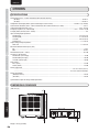
CONTENTS
FEATURES ................................................. 2
ADVANCED OPERATIONS ...................... 17
BEFORE USE ............................................. 2
HOW TO SET ID NUMBERS...............................17
NAMES AND FUNCTIONS ......................... 4
FRONT PANEL ......................................................4
DISPLAY................................................................5
REMOTE CONTROLLER ......................................6
REAR PANEL ........................................................7
BASIC CONNECTIONS .............................. 8
CONNECTING AUDIO COMPONENTS ...............8
CONNECTING SPEAKER SYSTEMS ..................9
CONNECTING OF AC POWER CABLE .............10
BASIC OPERATIONS ............................... 10
AMP OPERATION ...............................................10
ADVANCED CONNECTIONS ................... 12
CONNECTION TO THE P.DIRECT IN JACKS ....12
CONNECTION TO THE PRE OUT JACKS .........12
STEREO COMPLETE BI-AMP CONNECTION ....13
ATT (ATTENUATION) .........................................19
HOW TO OPERATE THE SIDE ILLUMINATION ...19
CONTROLLING MARANTZ COMPONENTS .....20
TROUBLESHOOTING .............................. 21
GENERAL ...........................................................21
PHONO ...............................................................22
ERROR MESSAGES ..........................................22
ABOUT THE PROTECTION CIRCUIT ................23
OTHERS .................................................... 24
SPECIFICATIONS ...............................................24
DIMENSIONAL DRAWINGS ...............................24
CLEANING OF EQUIPMENT EXTERNAL
SURFACES .........................................................25
USING HEADPHONES .......................................25
REPAIRS .............................................................25
ADVANCED CONNECTIONS
USAGE OF REMOTE CONTROLLER ..................3
TRIMMING ..........................................................18
ADVANCED OPERATIONS
INAPPROPRIATE PLACES FOR INSTALLATION ...2
BI-AMP MODE ....................................................17
TROUBLESHOOTING
EQUIPMENT MAINS WORKING SETTING ..........2
BASIC CONNECTIONS
Accessories check
BASIC CONNECTION FOR 5.1 MULTI-CHANNEL
PLAYBACK ..........................................................15
F.C.B.S. ...............................................................16
OTHERS
7
BASIC OPERATIONS
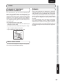
Thank you for choosing the Marantz product.
Please read this User Guide thoroughly to ensure proper operation and installation before using this product.
After reading this User Guide, be sure to keep this for your future reference.
NAMES AND FUNCTIONS
ENGLISH
1
ENGLISH
NAMES AND FUNCTIONS
FEATURES
The PM-15S2 is a successor model for the PM-15S1, adopting
leading-edge technologies developed for the higher-grade
PM-11S2 model.
¶ HDAM-SA3 Module
BASIC CONNECTIONS
The HDAM-SA3 is a key amplifier module for a current feedback
amplifier and is mounted on the voltage-current conversion
block, which is the most important part of an amplifier, for
further improved circuit stability and high-speed processing.
¶ Constant Current Feedback Phono Equalizer
BASIC OPERATIONS
The phono equalizer adopts a system that maintains the
current feedback at a constant level within the audible range,
and supports both the MC and MM cartridges. Thanks to
this system, extremely smooth sound over the entire band of
frequencies with less noise can be achieved.
¶ Linear Control Volume
ADVANCED CONNECTIONS
This volume control amplifier is a combination of the MAS6116
from MAS and the inverse NF-type current feedback amplifier.
The amplifier section adopts a fully discrete design, combining
the HDAM-SA3 and the HDAM-SA2.
¶ CD Direct Input Buffer Amplifier
An input buffer amplifier that uses the HDAM-SA2 is mounted
directly after the input jacks in order to directly convey highquality Super Audio CD sound.
ADVANCED OPERATIONS
¶ V/I Servo Current Feedback Power Amplifier
TROUBLESHOOTING
¶ F.C.B.S.
To further improve the stability of the power amplifier, the
V/I Servo system has been developed. With this system,
fluctuations in the output offset voltage are converted into
currents and compensated in Current mode. Thus, the audio
quality and stability can be enhanced with this newly developed
V/I Servo system.
BEFORE USE
EQUIPMENT MAINS WORKING
SETTING
Your Marantz product has been prepared to comply with the
household power and safety requirements that exist in your
area.
– Power requirements (U.S.A.) .......................AC 120V 60Hz
– Power requirements (Europe) ................AC 230V 50/60Hz
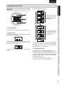
INAPPROPRIATE PLACES FOR
INSTALLATION
To keep your amplifier in perfect working order for the
longest possible time, avoid installing the unit in the following
locations.
• Wherever it will be exposed to direct sunlight
• Wherever it will be close to a heater or other heat-radiating
appliance
• Wherever the humidity is high or ventilation is poor
• Wherever it is very dusty
• Wherever it will be subject to vibration
• On top of a rickety stand or in an unstable location which is
tilted at an angle
• Near windows where there is a chance of exposure to rain,
etc.
• On top of an amplifier or other component which dissipates
a great deal of heat
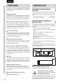
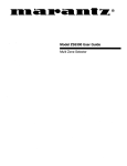
To ensure proper heat dissipation, install the unit while leaving
clearances between the unit and wall or other components, as
shown in the figure below.
Left 0.2 m
(7-7/8 in) or more
Above 0.2 m
(7-7/8 in) or more
Right 0.2 m
(7-7/8 in) or more
Rear 0.2 m (7-7/8 in) or more
A Floating Control Bus System enables the user to connect
up to four PM-15S2 units for linked operation. A diversity of
applications, such as complete bi-amp with two units and 5.1
multichannel connections with three units, become available.
¶ Power Amplifier Direct Input
OTHERS
With this function, this unit serves as a power amplifier.
As this function can be turned ON or OFF with a button on
the front panel, this unit can be used as part of various audiovisual systems.
7
Do not place objects on top
• Refrain from placing any objects on top of the unit.
¶ Double-Shielded Toroidal Transformer
¶ Double-Layered Chassis
2
Hot surface mark
Do not touch hot areas, especially
around the “hot surface mark” during
and immediately after use.
During and immediately after use, this product is hot in areas
other than the controls and rear panel connection jacks. Do not
touch hot areas, especially around the “hot surface mark” and
the top panel. Contact with hot areas can cause burns.
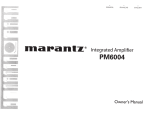
USAGE OF REMOTE CONTROLLER
Operational range
Operate the unit with the remote controller within the range of
the illustration below.
Loading batteries
Before using the remote controller for the first time, load the
batteries in the remote controller. The batteries provided are
used to verify the operations of the remote controller only.
Paying close attention to polarity indicators (ª plus and
· minus), be sure to insert batteries correctly and as
indicated.
Approx. 5 m (16.4 ft)
Precautions
3
¶ Cautions on handling batteries
Misusing batteries can lead to fire, injury or soiling of surrounding
area as a result of leakage, rupture or corrosion.
Carefully read the following precautions before using
batteries.
• Insert the batteries while ensuring that their ª and · poles
are properly aligned with the corresponding markings on the
remote controller.
• Batteries of the same size and shape may have different
voltages. Do not use any battery except the type indicated.
Do not use old and new batteries together, and do not use
different types of batteries together.
• Do not recharge batteries.
• Keep batteries out of the reach of children. Seek medical
attention if accidentally ingested.
• Do not carry or store batteries together with metal ball point
pens, necklaces, coins, hair pins, etc.
• If you will not be using the remote controller for an extended
time (1 month or more), remove the batteries to prevent
leakage. If batteries leak, do not touch the fluid with bare
hands. Wipe away any fluid in the case and put in new
batteries. When doing so, handle with care, because fluid
on skin or clothing presents a burn risk. If you accidentally
get fluid on your skin, immediately wash with water and seek
medical attention.
• Do not heat or take apart batteries or put them in flame or
water.
• Do not allow direct sunlight, an inverter fluorescent light or
other strong source of light to shine onto the players infrared
signal reception window (remote sensor). Otherwise, the
operation of the remote control unit may be disabled.
• Bear in mind that operating the remote control unit may
cause other devices operated by infrared rays to be operated
by mistake.
• The remote control unit cannot be operated if the space
between the controller and the players remote sensor is
obstructed.
• Do not place any objects on top of the remote control unit.
Doing so may cause one or more buttons to be held down
which will cause the batteries to run down.
ADVANCED CONNECTIONS
2
1
BASIC OPERATIONS
Return the battery cover to its original position.
ADVANCED OPERATIONS
3.
Remove the battery cover.
TROUBLESHOOTING
1.
2.
OTHERS
7
7
BASIC CONNECTIONS
BEFORE USE
NAMES AND FUNCTIONS
ENGLISH
• When disposing of used batteries, please comply with
governmental regulations or environmental public
instruction’s rules that apply in your country or area.
• Do not expose the batteries to excessive heat such as
direct sunlight, fire or the like.
3
ENGLISH
NAMES AND FUNCTIONS
NAMES AND FUNCTIONS
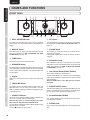
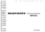
FRONT PANEL
q
w e r
t
yu i
o
BASIC CONNECTIONS
!0
!4
!3
!1
!0
BASIC OPERATIONS
ADVANCED CONNECTIONS
q INPUT SELECTOR Knob
i ATT Button
This knob is for selecting the input source to use in playback
and recording. The selected input source is displayed in the
display.
This button attenuates the volume with one press of the button.
For instructions on How to Set the Attenuation Level, see
page. 19.
w DISPLAY Button
o VOLUME Knob
This button turns the display and side illumination ON and
OFF. For instructions on HOW TO OPERATE THE SIDE
ILLUMINATION, see page. 19.
This knob is for setting the volume. The volume level is
displayed on the display.
During power amplifier direct mode, the volume cannot be
changed.
e TONE Button
ADVANCED OPERATIONS
This button turns the tone control ON or OFF.
!0 Illumination Lamp
r SPEAKERS Button
The illumination lamp casts a blue light over the switches
and buttons. It can be turned ON and OFF with the DISPLAY
button. For instructions on HOW TO OPERATE THE SIDE
ILLUMINATION, see page. 19.
This button turns the speaker output to the speakers connected
to the SPEAKER SYSTEMS terminals on the rear panel ON
or OFF. To listen with headphones, turn speaker output OFF
with this button.
t Display
TROUBLESHOOTING
Indicate the selected input source, volume level, and setting
status.
y PHONO MC Button
This button switches the phono equalizer between MC and
MM. When MC is set, the center of the button is lit a blue
color. Set the phono equalizer amplifier according to the type
of cartridge you use.
u P.DIRECT IN Button
OTHERS
4
!2
To use this unit as a power amplifier, hold this button pressed
for at least 3 seconds until the indicator lights.
While this unit serves as a power amplifier, the volume
level cannot be adjusted with the VOLUME knob.
To cancel power amplifier direct mode, hold this button pressed
again for at least 3 seconds.
See also t P.DIRECT IN Jacks, page 7.
!1 Tone Control Knobs (BASS, TREBLE)
These knobs control bass and treble tones.
The bass and treble tones are increased as the corresponding
knobs are turned clockwise and decreased as they are turned
counterclockwise.
When the TONE button is set to OFF, the tone cannot be
controlled.
!2 POWER ON/OFF Switch
This switch turns power to the unit ON and OFF. When pressed,
power is activated and the blue indicator in the display lights
up. Pressing the switch again turns the power OFF.
!3 Infrared Receptor Window
This receptor window receives control signals sent from the
included remote controller.
!4 PHONES Jack
This jack is for connecting headphones with a standard stereo
plug.
OPERATE
!7
0.5dB Steps
!5 Power Indicator
This indicator is lit a blue color while power to the unit is ON.
Turn the VOLUME knob on
the unit to the left, or press
the VOLUME ∞ button on the
remote controller.
!6 Display Panel
Approximately 3 seconds after the power to the unit is activated,
the ID number is displayed here.
Min
After that, the top line displays the selected input source,
and the bottom line displays the volume level. The volume
attenuation (dB units) is displayed.
During power amplifier direct mode, the volume cannot be
changed.
The display also displays the setting values when adjusting
the left-right level balance. For instructions on How to Trim
Volume Level, see page. 18. Other messages that correspond
to various operations are also displayed.
!7 OPERATE Indicator
This indicator indicates the operating status of the unit.
When the ID is set to “0” for standalone operation, it is lit a red
color. When multiple amplifiers are connected by F.C.B.S., only
ID number “1” for the master is lit red color. The slave amplifier
whose indicator does not light a red color cannot be used to
operate other units in sync.
For more information on F.C.B.S., see page. 16.
The indicator flashes red if a protective circuit trips.
BASIC CONNECTIONS
!6
BASIC OPERATIONS
Turn the VOLUME knob on
the unit to the right, or press
the VOLUME 5 button on the
remote controller.
ADVANCED CONNECTIONS
!5
ADVANCED OPERATIONS
Max
TROUBLESHOOTING
VOLUME Indicator Volume Display
DISPLAY
OTHERS
NAMES AND FUNCTIONS
NAMES AND FUNCTIONS
ENGLISH
5
ENGLISH
NAMES AND FUNCTIONS
NAMES AND FUNCTIONS
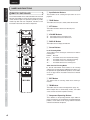
z Input Selector Buttons
REMOTE CONTROLLER
BASIC CONNECTIONS
This remote controller can be used to control the PM-15S2 and
Marantz Super Audio CD players or DVD players that have a
remote control receptor. The operations possible by remote
control may differ with each component, therefore see the
instruction manual that came with the component.
These buttons are for selecting the input source to use in
playback.
x TONE Button
This button turns tone (bass /treble) control ON and OFF.
c ATT Button
OPEN/
CLOSE
.
v VOLUME Buttons
PHONO
BALANCED
CD
BASIC OPERATIONS
RECORDER 1
LINE 1
RECORDER 2
LINE 2
TRIM
,
m
EXIT
z
x
+
ADVANCED CONNECTIONS
In the Trimming Mode
ENTER
DISPLAY
-
This button turns the display ON and OFF.
n Cursor Buttons
R
n
3 : This button increases the volume level.
4 : This button decreases the volume level.
b DISPLAY Button
TONE
L
b
This button attenuates volume level with one press.
(page. 19)
SOUND
MODE
ATT
c
v
VOLUME
These buttons are for selecting the channel to trim and the
trimming level.
ENTER : Not used.
2/R
: This button selects the R channel for trimming.
1/L
: This button selects the L channel for trimming.
3/+
: This button increases the trimming level.
4/–
: This button decreases the trimming level.
ADVANCED OPERATIONS
Other than the Trimming Mode
.
RANDOM
SCAN
REPEAT
TOP MENU
RETURN
MENU
AM/A
FM/B
2, 1, 3, 4 and ENTER: These buttons are for selecting
settings items on menu displays of Marantz DVD players, etc.
For operations of supported Marantz products, see the tables
on the 20 page and the instruction manual of the Marantz
component.
m EXIT Button
TROUBLESHOOTING
This button ends the trimming mode when trimming is
finished.
, TRIM Button
This button starts the various trim adjustments. (Page. 18)
When multiple units are connected by F.C.B.S., this button
selects the unit with which to perform trimming.
. Component Operating Buttons
OTHERS
6
These buttons are for operating Marantz Super Audio CD
players, DVD players, etc. For operations of supported Marantz
products, see the tables on the 20 page and the instruction
manual of the Marantz component.
P.DIRECT
IN
PRE OUT
o
F.C.B.S.
L
L
SPEAKER SYSTEMS
L
SPEAKER IMPEDANCE : 4 - 8 OHMS
R
IN
R
R CH
L
L
R
IN
OUT
L CH
1 RECORDER 2
R
IN
IN
R
IN
1 LINE 2
BI.AMP
STEREO
IN
OUT
!2 !1
IN
OUT
!0
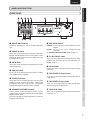
q PHONO GND Terminal
u AMP MODE Switch
Connect the grounding wire from an analog record player
here.
STEREO : Set to use this unit as a normal two-channel stereo
amplifier.
BI-AMP : Set to use this unit in complete bi-amp
connection.
For STEREO COMPLETE BI-AMP mode, see page 13.
w PHONO IN Jacks
These jacks are for connecting to an analog record player.
Both MC and MM cartridges can be used, therefore set the
PHONO MC button on the front panel according to the type
of cartridge you are using.
e CD IN Jacks
These jacks are for connecting to the output jacks of a Super
Audio CD player, etc.
r PRE OUT Jacks
These jacks are for connecting to the input jacks of another
main amplifier or active subwoofer.
t P.DIRECT IN Jacks
These input jacks are used when this unit is used as a power
amplifier in power amplifier direct mode. Connect your
preamplifier to these jacks, if you have them. During power
amplifier direct mode, the volume cannot be changed.
i F.C.B.S. IN/OUT Jacks
These jacks are used to connect and synchronize up to four
amplifiers. For instructions on use and connections, see
F.C.B.S. (page. 16).
o AC IN Socket
Connect this socket to the power outlet using the included
power cord.
!0 RECORDER 1/2 Output Jacks
These jacks are for connecting to the recording input jacks of
a tape deck etc.
!1 RECORDER 1/2 Input Jacks
These jacks are for connecting to the output jacks of a tape
deck or other type of recording device.
y SPEAKER SYSTEMS Terminals
!2 LINE 1/2 IN Jacks
These terminals are for connecting a speaker systems.
Speaker output can be turned ON/OFF from the SPEAKERS
button on the front panel.
When in bi-amp mode, the signals input into the L channel are
output from both channels.
These jacks are for connecting to the output jacks of a tuner,
DVD player, etc.
BASIC CONNECTIONS
CD
u i
BASIC OPERATIONS
PHONO
PHONO
GND
y
e r t
ADVANCED CONNECTIONS
w
ADVANCED OPERATIONS
q
TROUBLESHOOTING
REAR PANEL
OTHERS
NAMES AND FUNCTIONS
NAMES AND FUNCTIONS
ENGLISH
7
ENGLISH
NAMES AND FUNCTIONS
BASIC CONNECTIONS
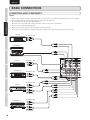
CONNECTING AUDIO COMPONENTS
Notes:
BASIC CONNECTIONS
• Do not connect this unit and other components to mains power until all connections between components have been completed.
• Insert all plugs and connectors securely. Incomplete connections may make noise.
• Be sure to connect the left and right channels properly.
Red connectors are for the R (right) channel, and white connectors are for the L (left) channel.
• Be sure to connect input and output properly.
• Refer to the instructions for each component that is connected to this unit.
• Do not tie the connected cable into a bundle with the power supply cord or speaker cables. Doing so may cause noise.
CD Player
To LINE OUT jack
SUPER AUDIO CD PLAYER SA-15S1
OPEN/
CLOSE
PLAY
BASIC OPERATIONS
DISPLAY OFF
STOP
POWER ON/OFF
SOUND
MODE
PONES
LEVEL
PAUSE
Record player
ADVANCED CONNECTIONS
To LINE OUT jack
Tuner, etc.
CD
PRE OUT
P.DIRECT
IN
L
ADVANCED OPERATIONS
R
IN
L
L
R
R
IN
1 LINE 2
1 RECORDER 2
L
DVD Player, etc.
DVD PLAYER DV-12S1
VIDEO ON/OFF
DIMMER
OPEN/CLOSE
To LINE OUT jack
PLAY
STOP
L
R
R
PAUSE
RANDOM
IN
V-PART
GRP
TITLE
POWER
STANDBY
DVD
AUDIO
192kHz
96kHz TRK
DIG OFF CHP
LAST MEMO
CONDITION
DOWN MIX
PROGRESSIVE
DOLBY D
TEMAIN
TOTAL VIDEO OFF
L
LS
C R
LFE
S RS
FL OFF
TROUBLESHOOTING
To LINE OUT jack
CD-R, etc.
To LINE IN jack
OTHERS
To LINE OUT jack
Tape deck, etc.
To LINE IN jack
8
PHONO
PHONO
GND
IN
IN
OUT
IN
OUT
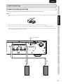
CONNECTING SPEAKER SYSTEMS
• Be sure to use speakers with the specified impedance as shown on the rear panel of this unit.
Note:
• To prevent damage to circuitry, do not let the bare speaker wires touch each other and do not let them touch any metal part of this
unit.
BASIC CONNECTIONS
BASIC CONNECTIONS
NAMES AND FUNCTIONS
ENGLISH
• Do not connect two or more speaker cables to a speaker terminal at the same time. If you do so, this unit may be damaged.
ADVANCED CONNECTIONS
• Be sure to connect the positive and negative cables for the speaker properly. If they are miss-connected, the signal phase will be
reversed and the signal quality will be corrupted.
Set to “STEREO”
F.C.B.S.
SPEAKER SYSTEMS
BI.AMP
STEREO
OUT
TROUBLESHOOTING
L CH
OTHERS
R CH
IN
ADVANCED OPERATIONS
SPEAKER IMPEDANCE : 4 - 8 OHMS
BASIC OPERATIONS
• Do not touch the speaker terminals when the power is on. It may cause you to receive an electric shocks.
L CH speaker
R CH speaker
9
ENGLISH
NAMES AND FUNCTIONS
BASIC OPERATIONS
BASIC CONNECTIONS
7
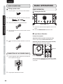
1.
Wiring speaker cable
Strip away approx. 10 mm (3/8 inch) of wire insulation.
AMP OPERATION
7
Turning the Unit ON
10 mm
(3/8 in)
BASIC CONNECTIONS
2.
Twist the bared wire ends tight, to prevent short circuits.
3.
Loosen the knob by turning it counterclockwise.
POWER ON/OFF button
BASIC OPERATIONS
4.
Insert the bare part of the wire into the hole in side of
each terminal.
1.
Turn on the connected audio equipment, such as a CD
player.
2.
Press the POWER ON/OFF button of this unit.
7
Input Source Selection
ADVANCED CONNECTIONS
Example: CD playback
(Operation with the controls on the main unit)
Set to CD by turning the INPUT SELECTOR knob.
5.
Tighten the knob by turning it clockwise to secure the
wire.
(Operation with the controls on the remote controller)
Press the CD button on the remote controller.
ADVANCED OPERATIONS
OPEN/
CLOSE
PHONO
SOUND
MODE
BALANCED
LINE 1
RECORDER 2
TRIM
LINE 2
EXIT
CONNECTING OF AC POWER CABLE
TROUBLESHOOTING
1.
Plug the supplied AC power cable to the AC IN socket on
the rear panel of the main unit.
AC IN
OTHERS
2.
Plug the power cable into an AC outlet.
TONE
+
L
10
CD
CD button
RECORDER 1
INPUT SELECTOR knob
R
ENTER
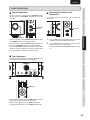
To use the speakers connected to the SPEAKER SYSTEMS
terminals, press the SPEAKERS button on the front panel to
set it to ON.
BASIC OPERATIONS
7
Volume Adjustment
Adjust the volume as desired with the VOLUME knob on
the front panel or the VOLUME 3 or 4 button on the remote
controller.
Attenuating the Volume Level
Temporarily
The volume level from the speakers can be temporarily
attenuated.
R
L
DISPLAY
-
ATT
ENTER
VOLUME34
buttons
VOLUME
DISPLAY
-
ATT
ATT button
VOLUME
BASIC CONNECTIONS
7
NAMES AND FUNCTIONS
ENGLISH
BASS
TONE button
PHONO
Tone control knobs
BALANCED
RECORDER 1
CD
LINE 1
RECORDER 2
TRIM
TREBLE
LINE 2
EXIT
TONE
TONE button
+
2.
Press the ATT button on the front panel or on the remote
controller again to cancel attenuation.
For details on How to Set Attenuation Level, see page
19.
ADVANCED CONNECTIONS
Tone Adjustment
According to your preference and acoustic conditions of the
room, the bass and treble tones can be adjusted.
Press the ATT button on the front panel or on the remote
controller to attenuate the output volume level.
ADVANCED OPERATIONS
7
1.
TROUBLESHOOTING
To increase volume, turn the VOLUME knob clockwise or press
the VOLUME 3 button on the remote controller.
To decrease volume, turn the VOLUME knob counterclockwise
or press the VOLUME 4 button on the remote controller.
When the VOLUME knob on the front panel is turned slowly,
the volume can be fine-adjusted in 0.5 dB steps, whereas when
it is turned rapidly, the volume level changes greatly.
BASIC OPERATIONS
ATT button
VOLUME knob
R
L
ENTER
-
ATT
Before adjusting the tone, press the TONE button on the front
panel or on the remote controller to set it to ON.
For bass tone adjustment, turn the BASS control knob.
For treble tone adjustment, turn the TREBLE control knob.
OTHERS
DISPLAY
11
ENGLISH
NAMES AND FUNCTIONS
ADVANCED CONNECTIONS
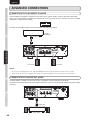
CONNECTION TO THE P.DIRECT IN JACKS
If an AV amplifier or preamplifier is available, this unit can be used as a power amplifier, using the connections shown below.
For this use, hold the P.DIRECT IN button on the front panel of this unit pressed for at least 3 seconds to set it to ON. “POWER
AMP DIRECT” is displayed on the display.
BASIC CONNECTIONS
For details on preamplifier operations, refer to the operation manual of the preamplifier.
AV amplifier,
preamplifier, etc.
To PRE OUT jacks
BASIC OPERATIONS
PHONO
PHONO
GND
CD
P.DIRECT
IN
PRE OUT
F.C.B.S.
L
L
SPEAKER SYSTEMS
L
BI.AMP
STEREO
SPEAKER IMPEDANCE : 4 - 8 OHMS
R
R
ADVANCED CONNECTIONS
IN
R CH
L CH
1 RECORDER 2
L
L
R
R
IN
IN
IN
OUT
IN
OUT
ADVANCED OPERATIONS
R CH speaker
L CH speaker
Notes:
• To cancel power amplifier direct mode, hold the P.DIRECT IN button on the front panel pressed for at least 3 seconds.
• Before setting the unit to power amplifier direct mode, turn off the preamplifier or set the volume level to the minimum.
CONNECTION TO THE PRE OUT JACKS
TROUBLESHOOTING
If a power amplifier is available, this unit can be used as a preamplifier, using the connections shown below.
For details on connections between the power amplifier and speaker system, refer to the operation manual of the power amplifier
to be used.
PHONO
PHONO
GND
CD
PRE OUT
P.DIRECT
IN
F.C.B.S.
L
L
SPEAKER SYSTEMS
L
SPEAKER IMPEDANCE : 4 - 8 OHMS
R
IN
R
R
R CH
IN
1 LINE 2
L
R
R
IN
L CH
1 RECORDER 2
L
IN
IN
OUT
IN
OUT
OTHERS
To input jacks
Speaker
12
OUT
R
IN
1 LINE 2
IN
Power amplifier
Speaker
BI.AMP
STEREO
IN
OUT
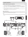
STEREO COMPLETE BI-AMP CONNECTION
1.
The two amplifiers are connected by F.C.B.S. for synchronized use. For F.C.B.S. connection, connect with commercially available
monaural ⇔ monaural miniplugs or stereo ⇔ stereo miniplugs as described in F.C.B.S. (page. 16).
2.
Set the ID numbers as explained in HOW TO SET ID NUMBERS (page. 17). When the ID1 amplifier is operated, the ID 2
amplifier will operate in sync. Set the AMP MODE switch on the rear panel to BI-AMP, referring to BI-AMP MODE (page
17).
3.
Connect the analog output of the CD player etc. to the L ch input jacks of both pre-amps.
As both amplifiers operate as monaural amplifiers in BI-AMP mode, do not use the R channel of the input jacks on these
units.
Set the SPEAKERS button on the front panel of the two amplifiers to ON.
BASIC CONNECTIONS
ADVANCED CONNECTIONS
NAMES AND FUNCTIONS
ENGLISH
Proposed by Marantz, the complete bi-amp connection is an advanced technique that enhances sound quality. The low and mid/high
amplifiers are separated and independent of the preamplifier, therefore interference between low and mid/high sounds is reduced
to a minimum. As a result, a wide sound environment can be reproduced.
Note:
Super Audio CD player, etc.
OPEN/
CLOSE
PLAY
STOP
PAUSE
PHONO
PHONO
GND
CD
PRE OUT
Rch
(ID 2) BI.AMP
BI.AMP
P.DIRECT
IN
F.C.B.S.
L
SPEAKER SYSTEMS
L
R
BI.AMP
STEREO
IN
P.DIRECT
IN
L CH
IN
1 RECORDER 2
R
R CH
L
L
L
R
R
R
OUT
IN
OUT
IN
IN
OUT
L CH
IN
OUT
IN
OUT
OTHERS
IN
IN
1 RECORDER 2
L
IN
BI.AMP
STEREO
R
IN
1 LINE 2
R
IN
F.C.B.S.
SPEAKER SYSTEMS
L
SPEAKER IMPEDANCE : 4 - 8 OHMS
R
R CH
PRE OUT
OUT
R
IN
1 LINE 2
CD
L
L
SPEAKER IMPEDANCE : 4 - 8 OHMS
R
IN
PHONO
PHONO
GND
L
TROUBLESHOOTING
Lch
(ID 1)
ADVANCED OPERATIONS
ADVANCED CONNECTIONS
Speaker systems connected using complete bi-amp connections must support bi-amp connections. Before connecting your speakers,
check in the instruction manual that came with the speakers or contact the manufacturer to confirm whether they support bi-amp
connection.
BASIC OPERATIONS
¶ About Complete Bi-Amp
MF / HF
MF / HF
LF
LF
Remove
L CH speaker
Remove
shorting bar.
shorting bar.
Remove R CH speaker
Remove
shorting bar.
shorting bar.
13
ENGLISH
NAMES AND FUNCTIONS
ADVANCED CONNECTIONS
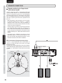
7
Speaker positioning for Super Audio
multi-channel sound
BASIC CONNECTIONS
In order to enjoy Super Audio CD multi-channel sound with
the best possible acoustics, it is recommended to position
speakers as specified in ITU-R BS.775-1 of the International
Telecommunication Union (ITU). Super Audio CD multi-channel
discs are recorded and mixed so as to achieve the optimum
effect with a speaker system laid out as specified in ITU-R
BS.775-1.
• With Super Audio CD multi-channel discs, the music signals
are basically recorded using 5 channels (3 - 6 channels
sometimes), but in some cases, LFE (for subwoofer) is
recorded as a sixth channel. Each disc indicates how many
channels have been recorded on it.
BASIC OPERATIONS
• The basic layout is 3 speakers in the front and 2 in the back
since multi-channel discs usually have 5 channels. The 2
front, 1 center and 2 surround (rear) speakers should be set
in a circle around the listening point as shown below. If using
speakers of differing sizes, adjust volume balance from the
amplifier.
ADVANCED CONNECTIONS
• The location of the subwoofer in the figure is just for
explanatory purposes. It can be located anywhere in the
room. For connection and positioning instructions, see the
instruction manual that came with the subwoofer.
¶ ITU (International Telecommunication Union)
ADVANCED OPERATIONS
The ITU is a special organization of the United Nations. It
consists of a number of organs, one of which is the Radio
Broadcasting Section.
ITU-R BS in the recommendation which consists of standards
relating to broadcasting (audio) operations, one of which is the
ITU-R BS.775-1 which governs “multi-channel stereo sound
systems.”
FRONT R / FRONT L
(ID 1)
PHONO
PHONO
GND
PRE OUT
P.DIRECT
IN
F.C.B.S.
L
Center
speaker
Sub-woofer
CD
L
L
R
R
SPEAKER SYSTEMS
SPEAKER IMPEDANCE : 4 - 8 OHMS
R
IN
R CH
IN
1 LINE 2
Front speaker
(Right)
Front speaker
(Left)
BI.AMP
STEREO
IN
L CH
1 RECORDER 2
L
L
R
R
IN
IN
IN
OUT
IN
OUT
TROUBLESHOOTING
60°
approx. 110°
approx. 110°
OTHERS
Reference listening
position
Rear speaker
(Left Surround)
Rear speaker
(Right Surround)
L CH
front speaker
14
STEREO
R CH
front speaker
OUT
ADVANCED CONNECTIONS
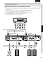
BASIC CONNECTION FOR 5.1 MULTI-CHANNEL PLAYBACK
1.
The three units are connected using F.C.B.S. For the F.C.B.S connection, prepare 3 audio connection cables, and refer to
F.C.B.S. on page 16.
2.
Set the ID numbers for the three amplifiers as explained in HOW TO SET ID NUMBERS (page. 17).
BASIC CONNECTIONS
When the ID 1 unit is operated, ID 2 and ID 3 units will operate in sync.
Connect the outputs of players that have 5.1 channel analog outputs to each of the three units.
Set the SPEAKERS button on the front panel of the three amplifiers to ON.
Set the AMP MODE switch on the rear panel to STEREO.
BASIC OPERATIONS
SACD multi-channel player, etc.
MULTI CHANNEL AUDIO OUT
FRONT L
SURROUND R SURROUND L SUB-WOOFER
CENTER
CENTER / SUB-WOOFER
(ID 2)
PHONO
PHONO
GND
CD
PRE OUT
STEREO
P.DIRECT
IN
F.C.B.S.
L
L
R
R
SPEAKER SYSTEMS
SPEAKER IMPEDANCE : 4 - 8 OHMS
IN
1 LINE 2
BI.AMP
STEREO
IN
L CH
IN
1 RECORDER 2
L
L
R
R
OUT
IN
L
R
F.C.B.S.
SPEAKER SYSTEMS
OUT
R CH
BI.AMP
STEREO
IN
L CH
1 RECORDER 2
L
OUT
R
IN
IN
IN
OUT
IN
OUT
TROUBLESHOOTING
IN
P.DIRECT
IN
L
R
IN
1 LINE 2
L
IN
PRE OUT
SPEAKER IMPEDANCE : 4 - 8 OHMS
R
IN
CD
L
OUT
R
R CH
IN
PHONO
PHONO
GND
L
R
STEREO
SURROUND R /
SURROUND L(ID 3)
ADVANCED OPERATIONS
ADVANCED CONNECTIONS
FRONT R
OTHERS
3.
4.
5.
NAMES AND FUNCTIONS
ENGLISH
To line input
jack
Active subwoofer
Front center speaker
L CH surround
speaker
R CH surround
speaker
15
ENGLISH
NAMES AND FUNCTIONS
ADVANCED CONNECTIONS
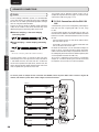
F.C.B.S.
BASIC CONNECTIONS
F.C.B.S. (Floating Control Bus System) is a communication
system that connects up to four PM-15S2s over a dedicated
bus line so as to enable synchronized operations amongst
them via 2-way data communications.
Prepare the correct number of portable audio connection
cables for the number of units to be connected. Any of the
following two types of connecting cables can be used.
¶ Monaural miniplug ⇔ monaural miniplug
connecting cable
BASIC OPERATIONS
¶ Stereo miniplug ⇔ stereo miniplug connecting
cable
Note:
Do not use connecting cables that contain resistance.
ADVANCED CONNECTIONS
The figure below shows an example of four PM-15S2s
connected by F.C.B.S. The top unit is the master unit with ID
1 and controls the three slave units with ID 2~4. When the
master unit is operated, the input source, volume level, ATT
feature, display and tone control ON/OFF feature of the slave
units are operated in sync with the master unit.
This function can be applied to various usages such as
complete bi-amp with 2 PM-15S2s (page. 13), and 5.1ch multichannel with 3 PM-15S2s (page. 14, 15).
7
F.C.B.S. Connection with the PM-11S2
Unit
A multichannel system can be configured by connecting the
PM-15S2 units with a higher-grade PM-11S2 unit, using
F.C.B.S.
As higher-grade functions are provided with the PM-11S2
than with this unit, follow the connection conditions described
below for an F.C.B.S. connection between the PM-11S2 and
this unit.
• Limit the number of PM-11S2 units to one and that of the
PM-15S2 units to up to 3.
• Set the PM-11S2 unit as the ID 1 Master and the PM-15S2
units as one of the ID2–4 slave units.
For details on connections, see the connection examples on
pages 14 and 15. If the PM-15S2 for the front L/R channels
shown in the connection example is replaced with a PM-11S2,
the audio quality of the front channels could be improved (also
see the operation manual for the PM-11S2.)
To use the 5.1 multichannel system shown as a connection
example as a 2-channel stereo system, turn off the ID2 and
ID3 amplifiers. Thus, the PM-11S2 can be used alone.
ADVANCED OPERATIONS
To turn the power of multiple F.C.B.S.-connected units ON/OFF, switch the power ON in order of lowest to highest ID
number, and switch the power OFF in order of highest to lowest ID number.
PM-15S2
F.C.B.S.
TROUBLESHOOTING
ID 1 Master
IN
F.C.B.S.
OUT
IN
OUT
PM-15S2
F.C.B.S.
ID 2 Slave
IN
F.C.B.S.
OUT
IN
OUT
PM-15S2
OTHERS
F.C.B.S.
ID 3 Slave
IN
F.C.B.S.
OUT
IN
OUT
PM-15S2
F.C.B.S.
IN
ID 4 Slave
16
F.C.B.S.
OUT
IN
OUT
The ID number of the unit appears on the display for about 3
seconds after the power is activated.
When multiple PM-15S2s are connected, a unique ID number
must be set of each one in order to distinguish between
them.
The unit that centrally controls the other units takes ID 1.
The unit with ID1 is called the “Master”. The other units that
synchronize with the master are called “slaves” and take IDs
“2” ~ “4”.
INPUT SELECTOR Knob
BI.AMP
STEREO
The bi-amp mode is engaged by setting the operating mode
switch on the rear panel to “BI-AMP”.
In the bi-amp mode, the signals input to the L channel are sent
to the left and right volume amplifiers from the input selector.
The figures below show example displays in the stereo and
bi-amp modes.
Stereo mode
DISPLAY button
Bi-amp mode
Notes:
• Always turn the power to the unit OFF before changing the
operating mode switch setting. Turning the power ON again
activates the new setting.
POWER ON/OFF Switch
Set ID numbers as follows.
While pressing and holding the DISPLAY button, press
the POWER ON/OFF switch.
2.
Turn the INPUT SELECTOR knob to the desired ID
number.
• When in bi-amp mode, the signals input into the L channel
are output from both channels. Therefore, the same signals
are output from the L channel and R channel in RECORDER
OUT, PRE OUT, PHONES OUT.
OTHERS
1.
• When in bi-amp mode, the R channel input jacks cannot be
used.
BASIC CONNECTIONS
If the ID number is set to a number other than “0”, this unit
cannot be used for standalone operation.
BASIC OPERATIONS
Note:
This unit is equipped with a bi-amp mode to enable a complete
bi-amp connection using two PM-15S2s. This complete
bi-amp connection is a high-end technique for enhancing
sound quality, proposed by Marantz. Using this system, the
bi-amp supporting speaker system is separated from the
preamplifiers that separately drive the low and high speakers.
(For more information, see STEREO COMPLETE BI-AMP
CONNECTION (page.13).)
ADVANCED CONNECTIONS
If using this unit by itself as a stereo amplifier, set the ID number
to “0” (Default setting is “0”).
BI-AMP MODE
ADVANCED OPERATIONS
HOW TO SET ID NUMBERS
TROUBLESHOOTING
ADVANCED OPERATIONS
NAMES AND FUNCTIONS
ENGLISH
After finishing setting the ID number, turn power to the unit
OFF.
The setting is stored in memory and becomes active the next
time power to the unit is switched ON.
17
ENGLISH
NAMES AND FUNCTIONS
BASIC CONNECTIONS
BASIC OPERATIONS
ADVANCED CONNECTIONS
ADVANCED OPERATIONS
TROUBLESHOOTING
OTHERS
18
ADVANCED OPERATIONS
7
TRIMMING
LEVEL trimming that adjusts the volume level on left and right
channels
Note:
How to Trim Volume Level
The volume level of the left and right channels can be trimmed
in 0.5dB steps across a 0.0 to -9.0dB range. When the unit
is shipped from the factory, the volume level is set to 0.0dB
(maximum).
Trimming is performed from the remote controller.
TRIM : This button starts trimming. When multiple PM15S2s are connected, this button selects the
amplifier with which to perform trimming. In such
case, trimming is performed in the order of the
lowest to highest ID number.
EXIT : This button ends trimming.
3 : This button increases the trimming level.
4 : This button decreases the trimming level.
2 : This button selects the R channel for trimming.
1 : This button selects the L channel for trimming.
ENTER : Not used
OPEN/
CLOSE
PHONO
BALANCED
2.
The flashing “0.0” on the left indicates that trimming is
activated for the left channel volume level. Press the 3 and
4 buttons to set the volume level of the left channel.
3.
Press the 2 button to set the right channel volume level.
When the right side “0.0” starts flashing, trimming is
activated for the right channel volume level. Press the
3 and 4 buttons to set the volume level of the right
channel.
4.
To trim the volume level of the ID 2 (slave) unit, press the
TRIM button again and set the volume level as in steps
1~3. After that, pressing the TRIM button again allows you
to trim the volume level for the “ID 3” unit and so forth.
5.
When finished with volume level trimming, press the EXIT
button.
CD
LINE 1
RECORDER 2
TRIM button
EXIT button
Press the TRIM button once to access the LEVEL
trimming mode.
SOUND
MODE
RECORDER 1
TRIM
1.
LINE 2
EXIT
TONE
+
L
R
3, 4, 2, 1
button
ENTER
DISPLAY
-
ATT
VOLUME
RANDOM
SCAN
REPEAT
TOP MENU
RETURN
MENU
AM/A
FM/B
ADVANCED OPERATIONS
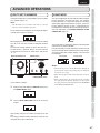
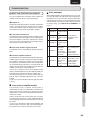
ATT (ATTENUATION)
2.
The attenuation level setting value changes with each
press of the ATT button on the unit.
3.
When the desired attenuation level setting appears on
the display, leave it unchanged for 2 seconds or longer
to enter the setting. Once entered, the display returns to
the volume level indication.
ATT button
VOLUME
ATT is a one-touch feature for reducing the volume level. When
the ATT button on either the unit or remote controller is pressed,
the volume level is attenuated.
1.
When the ATT button on either the unit or the remote
controller is pressed, “ATT” flashes on the display and
the volume level is reduced.
When the ATT button is pressed again or the volume
is increased/decreased using the controls, the mode is
canceled and the original volume level is restored.
2.
When the ATT button is pressed with the volume level at
-'(muted), the display will change as it is shown below
appears for about 3 seconds, and attenuation is not
applied.
7
How to Set Attenuation Level
Attenuation level can only be set using the ATT button on the
unit. The attenuation level can be set at –20dB, -40dB, or -'.
The factory default setting is -20dB.
1.
Press and hold the ATT button on the unit for 2 seconds or
longer. The attenuation level will appear on the display.
HOW TO OPERATE THE SIDE
ILLUMINATION
DISPLAY button
Illumination Lamp
The illumination lamp has an always-ON mode (factory setting)
and an always-OFF mode.
In the always-ON mode, the illumination lamp turns ON/OFF
in sync with the display.
1.
With the illumination lamp lit, press and hold the DISPLAY
button for 3 seconds or longer. The illumination lamp goes
out, and the always-OFF mode is engaged.
2.
To cancel the always-OFF mode and turn the illumination
lamp ON, press and hold the DISPLAY button for 3
seconds or longer.
ADVANCED CONNECTIONS
ATT
ADVANCED OPERATIONS
-
TROUBLESHOOTING
DISPLAY
Note:
Setting of the illumination lamp cannot be performed with the
remote controller.
OTHERS
ENTER
BASIC OPERATIONS
BASIC CONNECTIONS
ATT button
NAMES AND FUNCTIONS
ENGLISH
19
ENGLISH
NAMES AND FUNCTIONS
ADVANCED OPERATIONS
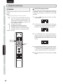
CONTROLLING MARANTZ COMPONENTS
1.
2.
Press the desired SOURCE button.
Press the desired operation buttons to play the selected component.
• For details, refer to the component’s user guide.
BASIC CONNECTIONS
• It may not be possible to operate some models.
TUNER
CD
OPEN/
CLOSE
SOUND
MODE
PHONO
BALANCED
RECORDER 1
CD
LINE 1
RECORDER 2
LINE 2
BASIC OPERATIONS
TRIM
EXIT
TONE
+
L
R
ENTER
-
DISPLAY
ATT
VOLUME
ADVANCED CONNECTIONS
RANDOM
SCAN
REPEAT
TOP MENU
RETURN
MENU
AM/A
FM/B
OPEN/
CLOSE
ADVANCED OPERATIONS
OPEN/
CLOSE
SOUND
MODE
BALANCED
TROUBLESHOOTING
RECORDER 1
RECORDER 2
TRIM
CD
LINE 1
LINE 2
EXIT
TONE
+
L
R
ENTER
DISPLAY
-
ATT
VOLUME
OTHERS
RANDOM
SCAN
REPEAT
TOP MENU
RETURN
MENU
AM/A
FM/B
Button
SOUND
MODE
PHONO
BALANCED
RECORDER 1
CD
LINE 1
RECORDER 2
LINE 2
TRIM
EXIT
TONE
+
L
R
ENTER
-
DISPLAY
ATT
VOLUME
RANDOM
SCAN
REPEAT
TOP MENU
RETURN
MENU
AM/A
FM/B
DVD
PHONO
20
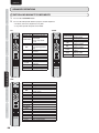
Button
Function
OPEN/CLOSE Open/Closes disc tray.
Selects Super Audio CD
sound mode.
SOUND MODE
Selects Super Audio
CD/CD.
3
Play
Track skip (Returns to
4
track beginning/previous
track.)
Track skip (Advances to
¢
next track.)
1
Rewind search
¡
Forward search
8
Pause
7
Stop
RANDOM
Random play
AMS (Automatic Music
SCAN
Scan) play
REPEAT
Repeat play
MENU 1 2
Sets quick replay.
ENTER
Starts quick replay.
Button
Function
OPEN/CLOSE Open/Closes disc tray.
SOUND MODE Changes sound mode.
3
Play
Track skip (Returns to track beginning/
4
previous track.)
¢
Track skip (Advances to next track.)
1
Rewind search
¡
Forward search
8
Pause
7
Stop
RANDOM
Random play
SCAN
Selects search mode.
REPEAT
Repeat play
TOP MENU/
Displays top menu.
AM/A
RETURN/FM/B Returns to previous menu
MENU 1 2
Displays menu screen.
ENTER
Sets selected item.
3 /+
Moves cursor upward.
4 /−
Moves cursor downward.
1/L
Moves cursor to left.
2/R
Moves cursor to right.
Function
Switches Auto Stereo/
SOUND MODE
Monaural mode.
4
Selects a preset station.
¢
Selects a preset station.
Tuning in to a higher1
frequency station.
Tuning in to a lower¡
frequency station.
Scanning of preset
SCAN
stations.
TOP MENU/
Switches to AM.
AM/A
RETURN/FM/B Switches to FM.
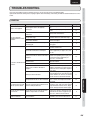
The batteries of the remote controller are
exhausted.
The remote controller is located outside
its operable range.
Some object is placed between the unit
and remote controller.
The remote sensor of the unit is exposed
to strong light.
Page
10
10
Replace with new batteries.
3
Check the operable range of the remote
controller and use it within that range.
3
Remove the object.
3
Avoid exposing the remote sensor to the
strong light.
Check the connection between the
Speaker connection is incomplete.
speakers and this unit.
Check the connection between the
Input cable connection is incomplete.
source equipment (CD player, etc.) and
this unit.
Set the INPUT SELECTOR knob to a
Setting of the INPUT SELECTOR knob is position corresponding to the input jacks
improper.
to which the source equipment (CD
player, etc.) is connected.
The speaker volume is set to the
Adjust the volume.
minimum level.
No sound is heard from the
The SPEAKERS button is set to OFF.
Set the SPEAKERS button to ON.
speakers.
To use the P.DIRECT IN jacks, hold the
P.DIRECT IN button pressed for at least 3
Setting of the P.DIRECT IN button is
seconds to set the unit to power amplifier
improper.
direct mode.
If “ATT” is displayed on the display, press
the ATT button on the main unit or on the
Muting has been activated.
remote controller, or increase the volume
level to cancel the attenuation function.
Turn the unit off then back on again after
The protection circuit has been activated. about 1 minute. Then adjust the volume
level again.
Set the trim levels for the left and right
The volume from the right The left- and right-channel volume levels channels to zero, and check that sound is
and left speakers differs.
(LEVEL TRIM) are different.
output from both channels. Then, adjust
the left- and right-channel volume again.
Check if the connection of cables
The left and right channels Connection of the left and right speaker between the speakers and this unit and
are reversed.
cables or input cables is reversed.
that between the source equipment (CD
player, etc.) and this unit are correct.
The MODE switch on the rear panel is
Turn the unit off, set the MODE switch to
Sound is monaural.
set to “BI-AMP”.
“STEREO”, then turn the unit back on.
3
9
8
10
11
4
7
11
23
18
ADVANCED OPERATIONS
This unit cannot be
controlled with the remote
controller.
The AC power cord is not properly
connected.
Solution
Plug the AC power cord firmly into the
unit.
Plug the AC power plug firmly into a wall
outlet.
TROUBLESHOOTING
Power is not supplied.
Cause
9
17
OTHERS
Symptom
BASIC CONNECTIONS
GENERAL
BASIC OPERATIONS
If you have any problem using this product, please be sure to check the items in the following table.
If you trouble cannot be solved, please unplug the power cable immediately and contact your Marantz authorized dealer or service
center.
ADVANCED CONNECTIONS
TROUBLESHOOTING
NAMES AND FUNCTIONS
ENGLISH
21
ENGLISH
NAMES AND FUNCTIONS
BASIC CONNECTIONS
BASIC OPERATIONS
ADVANCED CONNECTIONS
ADVANCED OPERATIONS
TROUBLESHOOTING
OTHERS
22
TROUBLESHOOTING
PHONO
Symptom
Cause
Grounding connection from the record
player is improper.
Noise occurs during record Connection to the PHONO IN jacks is
incomplete.
playing. Or, no sound is
heard.
A TV set, etc. placed too close to the
record player may affect the sound.
The PHONO MC button is not set
properly for the cartridge used.
The record player and speakers are
placed too close.
Howling occurs when
sound volume is increased
The record player is placed on a rack or
during record playing.
floor prone to vibration.
Solution
Check that the grounding wire of the
record player is connected with the
PHONO GND terminal of this unit.
Check that the output jacks of the record
player are properly connected with the
PHONO IN jacks of this unit.
Place the TV set or record player in
another position.
When the MC cartridge is used, set the
PHONO MC button to MC.
Place the speakers as far away from the
record player as possible.
If an insulating pad is not supplied with
the record player, use an insulating pad
available on the market.
Page
8
8
–
4
–
–
ERROR MESSAGES
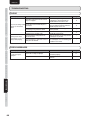
Symptom
An error message is
displayed.
Cause
Solution
Set the ID numbers for F.C.B.S
The F.C.B.S setting is improper.
connection properly.
See “ABOUT THE PROTECTION
The protection circuit has been activated.
CIRCUIT”.
Page
17
23
1
ERROR 02
2
ERROR 03
3
ERROR 04
¶ In the event of overcurrent
The protection circuit is activated if current exceeding a certain
level is detected, which can happen if excessive signal flow is
input to the amplifier or if the unit is connected to a speaker
system of less than 4 1 impedance. The protection circuit is
also activated if a speaker cable shorts.
¶ If excessive ultrabass signals are input
The protection circuit is also activated if ultrabass signals are
input.
4
ERROR 11
5
ERROR 12
¶ If the main-amplifier overheats
The protection circuit is activated if the temperature of the mainamplifier section rises above a certain level, which can happen
if the amplifier is continuously used with excessive signal flow
being input to it. The protection circuit is also activated when
the specified operating temperature is exceeded, which can
happen if the vents on top of the amplifier are covered or if the
amplifier is installed on a cramped audio rack.
In such cases, “PROTECT” flashes on the display, and the
volume is automatically decreased. After about 8 seconds, the
protection circuit is deactivated. Adjust the volume again.
If the abnormality persists, the unit will automatically shut
itself off, and the OPERATE indicator will flash (twice per
second).
In such a case, turn the unit off then back on again after about
1 minute.
7
In the event of amplifier trouble
The protection circuit is activated, and the power is
automatically shut OFF, if an abnormality is detected in the
power circuit. The same happens if the main fuse inside the
amplifier blows. In such cases, the OPERATE indicator flashes.
(8 times per second)
Turn the unit off then after several minutes turn it on again.
If the display does not light up, and the OPERATE indicator
remains flashing after the unit is turned on again, the unit may
be in failure.
In such a case, disconnect the power cord immediately, and
contact the place of purchase, your nearest Marantz dealer,
our customer service center, or our repair service center.
Meaning
Multiple
amplifiers take ID
No. 2.
Multiple
amplifiers take ID
No. 3.
Multiple
amplifiers take ID
No. 4.
The amplifiers
with ID Nos.
2-4 cannot
communicate
with the amplifier
with ID No. 1.
The amplifier with
ID No. 1 cannot
communicate
with the
amplifiers with ID
Nos. 2-4.
Measures to be taken
Assign different
ID numbers to the
amplifiers.
If the amplifier with ID
No. 1 is not on, turn
it ON.
Check that the
remote cable is
properly connected.
If multiple amplifiers
take ID No. 1, set ID
numbers properly.
Check that the
remote cable is
properly connected.
BASIC CONNECTIONS
Indication
BASIC OPERATIONS
For about 8 seconds after the power is turned on, the protection
circuit is activated, muting the sound to give the amplifier
circuits time to stabilize. Once the amplifier circuits stabilize,
the protection circuit is released, and audio is enabled.
ADVANCED CONNECTIONS
¶ At power on
Error messages
When multiple amplifiers are connected by F.C.B.S., the error
messages described in the table below may be displayed on
the display. In such a case, ID number setting or remote cable
connection may be in failure. Check the ID number or remote
cable connection, referring to the table below. For details on
ID number setting, see “HOW TO SET ID NUMBERS”, on
page 17.
ADVANCED OPERATIONS
This unit is equipped with a protection circuit to protect the
amplifier circuits and speaker system from damage.
7
TROUBLESHOOTING
ABOUT THE PROTECTION CIRCUIT
OTHERS
TROUBLESHOOTING
NAMES AND FUNCTIONS
ENGLISH
23
ENGLISH
SPECIFICATIONS
ADVANCED CONNECTIONS
ADVANCED OPERATIONS
DIMENSIONAL DRAWINGS
TROUBLESHOOTING
(Unit: mm (in))
19
(3/4)
105
(4-3/16)
123
(4-7/8)
OTHERS
Weight : 18.5 kg (40.8 lbs)
24
440 (17-3/8)
18
(3/4)
BASIC OPERATIONS
Specifications subject to change without prior notice.
25
(1)
BASIC CONNECTIONS
Power output (20 Hz – 20 kHz simultaneous drive of both channels)
(81 load) .....................................................................................................................................................................90 W x 2
(41 load) ...................................................................................................................................................................140 W x 2
Headphone rated output (When speaker rated output set to 8 1 load) ........................................................120mW x 2 (32 1 load)
Total harmonic distortion (20Hz – 20kHz simultaneous drive of both channels, 8 1 load).....................................................0.05 %
Output band width (81 load, 0.05%) .......................................................................................................................... 5 Hz ~ 40 kHz
Frequency response (CD, 1W, 81 load) .........................................................................................................5 Hz ~ 100 kHz ±3 dB
Dumping factor (81 load, 20Hz – 20kHz) .................................................................................................................................... 100
Input sensitivity/Input impedance
PHONO (MC) .........................................................................................................................................................270 μV/100 1
PHONO (MM) ........................................................................................................................................................ 2.7 mV/47 k1
CD/LINE ................................................................................................................................................................ 240 mV/20 k1
P.DIRECT IN ............................................................................................................................................................. 1.7 V/20 k1
Output voltage/Output impedance
PRE OUT .................................................................................................................................................................. 1.7 V/220 1
Maximum allowed PHONO input (1kHz)
MC .....................................................................................................................................................................................15 mV
MM ...................................................................................................................................................................................150 mV
RIAA deviation (20Hz ~ 20kHz) ............................................................................................................................................ ±0.5 dB
S/N (IHF-A, 1W, 81 load)
PHONO MC (0.5mV input)..................................................................................................................................................75 dB
PHONO MM (5mV input) ....................................................................................................................................................86 dB
CD/LINE (500mV input) ......................................................................................................................................................89 dB
Tone control
Bass (50Hz) ..................................................................................................................................................................... ±10 dB
Treble (20kHz).................................................................................................................................................................. ±10 dB
Power requirement
...........................................................................................................................................................AC 120 V 60 Hz (U.S.A.)
.................................................................................................................................................... AC 230 V 50/60 Hz (Europe)
Power consumption
(EN60065 7th Ed.) .............................................................................................................................................................220 W
(UL60065) ..........................................................................................................................................................................220 W
400 (15-3/4)
444 (17-1/2)
NAMES AND FUNCTIONS
OTHERS
• wipe the equipment with the damp cloth.
• dry the equipment by wiping it with a dry cloth.
USING HEADPHONES
If the volume in the headphones is too high, it may injure your
ears. Do not set the sound volume too high.
BASIC CONNECTIONS
BASIC OPERATIONS
• dip a soft, lint free in the solution and wring the it is damp.
ADVANCED CONNECTIONS
• dilute some washing up liquid in water, in a ratio of one part
detergent to six parts water.
Only the most competent and qualified service technicians
should be allowed to service the factory-trained warranty
station personnel have the knowledge and special facilities
needed for repair and calibration of this precision equipment.
After the warranty period has expired, repairs will be performed
for a charge if the equipment can be returned to normal
operation.
In the event of difficulty, refer to your dealer or write directly
to the nearest location to you that is listed on the Marantz
Authorized Service Station list. If writing, please include the
model and serial number of the equipment together with a full
description of what you think is abnormal about the equipment’s
behaviour.
ADVANCED OPERATIONS
The exterior finish of your unit will last indefinitely with
proper care and cleaning, Never use scouring pads, steel
wool, scourging powders or harsh chemical agents (e.g., lye
solution), alcohol, thinner, benzine, insecticide or other volatile
substances as these will mar the finish of the equipment.
Likewise, never use cloths containing chemical substances.
If the equipment get dirty, wipe the external surfaces with a
soft, lint-free cloth.
If the equipment becomes heavily soiled:
REPAIRS
TROUBLESHOOTING
CLEANING OF EQUIPMENT
EXTERNAL SURFACES
OTHERS
OTHERS
NAMES AND FUNCTIONS
ENGLISH
25
Memo
www.marantz.com
You can find your nearest authorized distributor or dealer on our website.
is a registered trademark.
Printed in Japan
05/2009 541110275035M mzh-g
lDapantz®
MARANTZ CANADA LIMITED WARRANTY
Marantz Canada ("Marantz") warrants the following Marantz
products for the periods indicated:
Who May Enforce the Warranty
3-year warranty for both Parts & Labour I from the original
purchase date:
What We Will Pay For
Only the original purchaser may enforce this warranty.
We will pay for all labor and material expenses for items
covered by the warranty. Payment of shipping charges is
discussed in the next section of this warranty.
Amplifiers; Pre Amplifiers; Pre Amplifier-Processor-Tuners;
Integrated Amplifiers; Tuners; Receivers; DVD Players; CDRecorders; CD Players; Audio Cassette Decks; Learning
Remote Control Devices; Universal Dock; Home Theater
Systems; Subwoofers & DLP front Projectors.
How You Can Get Service
1 year warranty for parts and labour from the original purchase
date:
HD Digital VCR's
90 day warranty for parts and labour from the original purchase
date:
DLPlamps
3-year warranty for Labour I 2-year warranty for parts and 1-year
warranty for the Panel:
Plasma Displays
What is Covered and What is Not Covered
Except as specified below, this warranty covers parts and
labor to correct all defects in materials and workmanship. The
following are not covered by the warranty:
1. Damage, deterioration, malfunction or failure to meet
performance specifications resulting from:
a) Accident; acts of nature; misuse; abuse; neglect;
unauthorized product modification.
b) Improper installation, removal or maintenance, or
failure to follow instructions supplied with the
product.
c) Repair or attempted repair by anyone not authorized
by Marantz to repair the product.
d} Any shipment of the product (claims must be
presented to the carrier)
e} Any cause other than a product defect
2. Cleaning, initial set-up, check-ups with no defects found,
or charges incurred for installation, removal or
reinstallation of the product.
3. Any product on which the serial number has been
defaced, modified or removed.
I
1. If your unit needs service, it may be taken or shipped to
any authorized MARANTZ service station or MARANTZ
CANADA (if you are uncertain as to whether a service
station is MARANTZ authorized, please contact
MARANTZ as listed below). Please do not return your
unit to the factory without prior authorization.
2. You must pay any shipping charged if it is necessary to
ship the product for service. However, if the necessary
repairs are covered under warranty, we will pay the
return shipping charges to any destination within
Canada.
3. Whenever warranty service is required, you must present
the original dated sales receipt or other proof of date of
purchase.
Limitation of Implied warranties
All implied warranties, including warranties of
merchantability and fitness for a particular purchase, are
limited in duration to the length of this warranty.
Exclusion of damages
Marantz liability for any defective product is limited to repair
or replacement of the product at Marantz's option. Marantz
shall not be liable for damage to other products caused by
any defects in Marantz products, damages based upon
inconvenience or loss of use of the product, or any other
damages, whether incidental, consequential, or otherwise.
Some provinces do not allow limitations on how long an
implied warranty lasts and / or does not allow the exclusion of
incidental or consequential damages, so the above limitations
and exclusions may not apply to you.
This warranty gives you specific legal rights, but you may
also have other rights, which vary from province to province.
4. Accessories, including but not limited to, batteries, cables,
mounting hardware and brackets, cleaning accessories,
antenna and detachable power cords.
5. Warranty is void if purchase was made from anyone
other than an authorized Marantz dealer.
MARANTZ Canada
Division of D&M Canada Inc.
5-505 Apple Creek Blvd.,
Markham, Ontario
L3R 5B1
1-888-258-9361
www.marantz.com
PRINTED IN JAPAN
B/07
00M1 B3JB54017
_apantz®
GARANTIE LlMITEE DE MARANTZ CANADA
Marantz Canada ("Marantz") garantie les produits suivants
pour les periodes indiquees :
3 ans de garantie pour les pieces et la main d'muvre prenant
effet it partir de la date d'achat du produit :
Amplificateurs, Preamplificateurs, Pre-ampli-processeurssyntoniseurs; amplificateurs integres, syntoniseurs,
recepteurs, lecteurs DVD, enregistreurs CD, lecteurs CD,
platines a cassette audio, telecommandes programmables,
Dock universe!, systeme de cinema a domicile, caisson de
basse et projecteurs avant DLP.
1 an de garantie pour les pieces et la main d'muvre prenant
effet it partir de la date d'achat du produit :
Magnetoscope numerique HD
90 jours de garantie pour les pieces et la main d'muvre prenant
effet it partir de la date d'achat du produit :
Lampes DLP
3 ans de garantie pour la main d'muvre, 2 ans de garantie pour
les pieces et un an de garantie pour Ie panneau :
Ecrans a plasma
Ce qui est couvert et pas couvert par la garantie :
A I'exception de ce qui est mentionne ci-dessous, cette
garantie couvre les pieces et la main d'ceuvre afin de reparer
tous les defauts de materiel ou de fabrication du produit. Ce
qui suit n'est pas couvert par.la garantie :
1. Les dommages, deterioration, defauts de fonctionnement,
Notre paiement
Nous paierons tous les frais de pieces et de main d'ceuvre
pour tous les produits couverts par la garantie. Le paiement
des frais de livraison est aborde dans la section suivante de
cette garantie.
Comment vous pouvez obtenir Ie service de reparation
1. Si vous avez besoin de faire reparer votre apparei!, vous
pouvez l'envoyer ou Ie deposer chez un atelier de service
autorise Marantz ou directement chez Marantz Canada
(Dans Ie cas ou vous n'etes pas sUr de savoir si un atelier de
service est autorise ou non a reparer votre apparei!, vous
pouvez contacter Marantz Canada a I'adresse et au numero
de telephone ci-dessous). Veuillez ne pas renvoyer votre
appareil a l'usine sans autorisation prealable.
2. Vous devez payer les frais de livraison dans Ie cas OU votre
appareil a besoin d'etre envoye au service des reparations.
Toutefois, si les reparations necessaires sont couvertes par
la garantie, nous payerons les frais de retour d'expedition
et ce quelle que soit la destination au Canada.
3. Lorsque vous envoyez votre appareil pour un service
sous garantie, vous devez joindre une copie de la facture
d'achat (ticket ou autre preuve d'achat)
Limites des garanties implicites
Toutes les garanties implicites, y compris les garanties de
valeur marchande et specifique pour un achat particulier,
sont limitees dans la duree a la longueur de cette garantie.
Exclusion des dommages
ou Ie fait de ne pas respecter les specifications d'executions
resultant d'un (e) :
a) accident, acte de la nature, abus, negligence, utilisation
impropre ou d'une modification de produit non
autorisee;
b) installation incorrecte, deplacement, maintenance ou
d'un emploi contraire aux instructions fournies avec
Ie produit;
c) reparations ou tentatives de reparations par une
personne non reconnue par Marantz;
d) envoi de produit (les reclamations doivent etre
presentees au transporteur)
e) cause autre qu'un defaut de produit.
La responsabilite de Marantz est limitee pour n'importe quel
produit defectueux en ce qui concerne la reparation ou Ie
remplacement du produit en question. Si des dommages
interviennent a des produits autres que ceux de Marantz,
Marantz ne sera pas tenu responsable des dits dommages,
bases sur Ie derangement ou la perte d'utilisation du produit
ou tout autre dommage qu'il soit fortuit, indirect ou autre.
2. L'entretien, I'installation initiale, toute verification de produit
ou aucun defaut n'a ete trouve, ou tous frais encourus pour
I'installation, Ie deplacement ou la reinstallation du produit.
Cette garantie vous donne des droits legaux specifiques, mais
vous pouvez aussi avoir d'autres droits qui peuvent varier
d'une province a l'autre.
3. Tout produit dont Ie numero de serie a ete efface, modifie
ou enleve.
4. Les accessoires incluant mais non limites aux, piles,
cables, materiaux de support, accessoires de nettoyage,
antennes et cordons de secteur detachables.
5. La garantie n'est pas valable si I' achat a ete fait au Canada
chez un revendeur non reconnu par Marantz.
Qui peut faire appliquer la garantie
Seule la personne qui a achete Ie produit a l'origine peut faire
appliquer la garantie.
Certaines provinces ne permettent pas de limites quant a la
duree d'une garantie sous-entendue etl ou ne permettent pas
l'exclusion de dommages fortuits ; ainsi les limitations et les
exclusions mentionnees ci-dessus peuvent ne pas s'appliquer
a votre cas.
Cette garantie n'est seulement valable qu' au Canada.
MARANTZ Canada
Division of D&M Canada Inc.
5-505 Apple Creek Blvd.,
Markham, Ontario
L3R 5B1
1-888-258-9361
www.marantz.com
PRINTED IN JAPAN
8/07
00M183J854017
For U.S.A.
_arantz®
Limited Warranty
Marantz America, Inc. ("Marantz") warrants the following Marantz
Products for the periods indicated:
Who may enforce the warranty
This warranty may be enforced only by the original purchaser.
1. The following Marantz Audio/Video components, have a 3
year warranty for both Parts & Labor, from the original purchase date:
Amplifiers, Pre Amplifiers, Pre Amplifier-ProcessorTuners, Integrated Amplifiers, Tuners, Receivers, DVD
Players, CD-Recorders, CD Players, Audio Cassette Decks,
Learning Remote Control Devices, Universal Dock, Home
Theater Systems, Subwoofers & DLP front Projectors.
2. VCR's, Wallvisions, Plasma TVs, LCD TVs & HOD
Products have a 1 year warranty for parts and labor from the
original purchase date.
3. Rear Projection TVs have a 2 year warranty for parts and
labor from the original purchase date.
4. DLP lamps have a 90 day warranty for parts and labor from
the origianl purchase date.
What is covered and what is not covered
Except as specified below, this warranty covers parts and labor
to correct all defects in materials and workmanship. The following are not covered by the warranty:
1. Damage, deterioration, malfunction or failure to meet performance specifications resulting from:
a) Accident, acts of nature, misuse, abuse, neglect or unauthorized product modification.
b) Improper installation, removal or maintenance, or failure to follow instructions supplied with the product.
c) Repair or attempted repair by anyone not authorized by
Marantz to repair the product.
d) Any shipment of the product (claims must be presented
to the carrier).
e) Any cause other than a product defect.
2. Cleaning, initial set-up, check-Ups with no defects found, or
charges incurred for installation, removal or reinstallation of
the product.
3. Any product on which the serial number has been defaced,
modified or removed.
4. Batteries.
5. Accessories, including but not limited to, batteries, cables,
mounting hardware and brackets, cleaning accessories,
antenna and detachable power cords.
What we will pay for
We will pay for all labor and material expenses for items covered by the warranty. Payment of shipping charges is discussed
in the next section of this warranty.
How you can get service
1. If your unit needs service, contact Marantz service referral by
calling toll-free 1-800-270-4533. We will advise you of the
name and location of one or more authorized Marantz service stations from which service can be obtained. Please do
not return your unit to the factory without prior authorization.
2. You must pay any shipping charged if it is necessary to ship
the product for service. However, if the necessary repairs are
covered under warranty, we will pay the return shipping
charges to any destination within the United States, its possessions or territories.
3. Whenever warranty service is required, you must present the
original dated sales receipt or other proof of date of purchase.
Limitation of implied warranties
All implied warranties, including warranties of merchantability
and fitness for a particular purchase, are limited in duration to
the length of this warranty.
Exclusion of damages
Marantz liability for any defective product is limited to repair or
replacement of the product at Marantz's option. Marantz shall
not be liable for damage to other products caused by any defects
in Marantz products, damages based upon inconvenience or
loss of use of the product, or any other damages, whether incidental, consequential, or otherwise.
How state law relates to the warranty
Some states do not allow limitations on how long an implied
warranty lasts and/ or do not allow the exclusion or limitation
of incidental or consequential damages, so the above limitations
or exclusions may not apply to you.
This warranty gives you specific legal rights, and you may also
have other rights which vary from state to state.
6. Warranty is void if purchase was made from anyone other
than an authorized Marantz dealer.
Marantz America, Inc.
100 Corporate Drive,
Mahwah, NJ, 07430
Phone. 800-654-6633 Fax. 201-762-6686
PRINTED IN JAPAN
8/07
3133 115 78064
092J854118